


 Loading...
Pulse Laser Station NPL-302 Series
Instruction Manual
NPL-332
NPL-352
NPL-362
H163E 05.10.TF.9

Contact Information
Nikon-Trimble Co. Limited
Copyright and Trademarks
© 2005, Nikon-Trimble Co. Limited. All rights reserved.
All trademarks are the property of their respective owners.
It is prohibited to alter this manual in part or whole without express permission.
The contents of this manual are subject to change without notice. Although every effort has been made to ensure the accuracy of this manual, please contact your dealer if you find anything in it that is incorrect or unclear.
Release Notice
This is the October 2005 release of the Pulse Laser Station NPL-302 Series Instruction Manual, part number H163E. It applies to release 05.10.TF.9 of the Pulse Laser Station NPL-302 series.
Notices
USA
FCC 15B Class B satisfied.
This equipment has been tested and found to comply with the limits for a Class B personal computer and peripherals, pursuant to Part 15 of the FCC Rules. These limits are designed to provide reasonable protection against harmful interference in a residential installation. This equipment generates, uses and can radiate radio frequency energy and, if not installed and used in accordance with the instructions, may cause harmful interference to radio communications. However, there is no guarantee that interference will not occur in a particular installation.
If this equipment does cause harmful interference to radio or television reception, which can be determined by turning the equipment off and on, the user is encouraged to try to correct the interference by one or more of the following measures:
–Reorient or relocate the receiving antenna.
–Increase the separation between the equipment and receiver.
–Connect the equipment into an outlet on a circuit different from that to which the receiver is connected.
–Consult the dealer or an experienced radio/TV technician for help.
C |
Warning – This equipment has |
|
been certified to comply with the |
|
limits for a Class B personal |
|
computer and peripherals, |
|
pursuant to Subpart B of Part 15 |
|
of FCC Rules. Only peripherals |
|
(computer input/output devices, |
|
terminals, printers, etc.) certified |
|
to comply with the Class B limits |
|
may be attached to this |
|
equipment. Operation with |
|
non-certified personal computer |
|
and/or peripherals is likely to |
|
result in interference to radio and |
|
TV reception. The connection of |
|
a non-shielded equipment |
|
interface cable to this equipment |
|
will invalidate the FCC |
|
Certification of this device and |
|
may cause interference levels |
|
which exceed the limits |
|
established by the FCC for this |
|
equipment. |
|
You are cautioned that changes |
|
or modifications not expressly |
|
approved by the party |
|
responsible for compliance could |
|
void your authority to operate the |
|
equipment. |
|
|
European Union
EU EMC Directive satisfied.
Canada
This Class B digital apparatus meets all requirements of the Canadian InterferenceCausing Equipment Regulations.
Cet appareil numérique de la Class B respecte toutes les exigences du Règlement sur le matériel brouilleur du Canada.

Taiwan
Battery Recycling Requirements
The product contains a removable battery. Taiwanese
regulations require that waste batteries are recycled.
Notice to Our European
Union Customers
For product recycling instructions and more information, please go to: www.trimble.com/environment/summ ary.html
Recycling in Europe
To recycle Trimble WEEE, call: +31 497 53 2430,
and ask for the “WEEE associate,”
or mail a request for recycling instructions to:
Trimble Europe BV
c/o Menlo Worldwide Logistics Meerheide 45
5521 DZ Eersel, NL
Safety
In this chapter:
QIntroduction
QLaser Safety
QWarnings and Cautions

Safety
Introduction
For your safety, read this instruction manual carefully and thoroughly before using the NPL-302 series instrument. Although Nikon products are designed for maximum safety, using them incorrectly or disregarding the instructions can cause personal injury or property damage.
You should also read the instruction manual for the battery charger, and the documentation for any other equipment that you use with a NPL-302 series instrument.
Note – Always keep the manual near the instrument for easy reference.
vi Pulse Laser Station NPL-302 Series Instruction Manual
Safety
Laser Safety
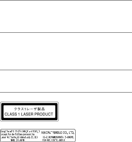
The NPL-362/352/332 is a Class 1 laser instrument. The laser beam is hazardous to the eyes and the body. Do not sight the instrument on the face or body of a person.
Specifications for laser emission
Wave length |
870 nm |
Drive method |
Pulse repetitive drive |
Output power |
< 6.4 W |
Pulse width |
<5 ns |
|
|
Conforming standards
E.U. EN60825-1/Am.2 : 2001 (IEC60825-1/Am.2 : 2001) : class 1
USA FDA21CFR Part 1040 Sec.1040.10 and 1040.11
(except for deviations pursuant to Laser Notice No.50, dated July 26, 2001) : class 1
Pulse Laser Station NPL-302 Series Instruction Manual vii

Safety
Warnings and Cautions
The following conventions are used to indicate safety instructions:
C
C
Warning – Warnings alert you to situations that could cause death or serious injury.
Caution – Cautions alert you to situations that could cause injury or property damage.
Always read and follow the instructions carefully.
Warnings
Before using the instrument, read the following warnings and follow the instructions that they provide:
C C
Warning – Never look at the sun through the telescope. If you do, you may damage or lose your eyesight.
Warning – NPL-302 series instruments are not designed to be explosion-proof. Do not use the instrument in coal mines, in areas contaminated with coal dust, or near other flammable substances.
C Warning – The NPL-302 series instrument is a Class 1 laser instrument. The laser beam is hazardous to the eyes and the body. Do not sight the instrument on the face or body of a person. If you suspect an injury caused by exposure to the laser beam, seek medical advice immediately.
If the instrument housing is open and the instrument is turned on, the laser emits a beam stronger than the Class 1 safety level.
C Warning – Never disassemble, modify, or repair the instrument yourself. If you do, you may receive electric shocks or burns, or the instrument may catch fire. You may also impair the accuracy of the instrument.
viii Pulse Laser Station NPL-302 Series Instruction Manual

Safety
C Warning – Use only the specified battery charger (part number Q-75U/E) to charge the battery pack (part number BC-65). Using other chargers, such as a charger with part number Q-7U/E or Q-7C, may cause the battery pack to catch fire or rupture. (The BC-65 cannot be charged by the Q-7U/E or Q-7C.)
C Warning – Do not cover the battery charger while the battery pack is being recharged. The charger must be able to dissipate heat adequately. Coverings such as blankets or clothing can cause the charger to overheat.
C Warning – Avoid recharging the battery pack in humid or dusty places, in direct sunlight, or near heat sources. Do not recharge the battery pack when it is wet. If you do, you may receive electric shocks or burns, or the battery pack may overheat or catch fire.
C Warning – Although the battery pack (part number BC-65) has an auto-reset circuit breaker, you should take care not to short circuit the contacts. Short circuits can cause the battery pack to catch fire or burn you.
C C
Warning – Never burn or heat the battery. Doing so may cause the battery to leak or rupture. A leaking or ruptured battery can cause serious injury.
Warning – Before storing the battery pack or battery charger, cover the contact points with insulation tape. If you do not cover the contact points, the battery pack or charger may short circuit, causing fire, burns, or damage to the instrument.
C Warning – The battery BC-65 is not waterproof on its own. Do not get the battery wet when it is removed from the instrument. If water seeps into the battery, it may cause a fire or burns.
Pulse Laser Station NPL-302 Series Instruction Manual ix

Safety
Cautions
Before using the instrument, read the following cautions and follow the instructions that they provide:
C Caution – Do not use controls or adjustments, or carry out any procedures, other than those specified in this document. Otherwise you may be exposed to hazardous radiation.
C C
Caution – The tops of the tripod ferrules are very sharp. When handling or carrying the tripod, take care to avoid injuring yourself on the ferrules.
Caution – Although a Class 1 laser is regarded as safe under normal operating conditions, it is recommended that you cap the objective when the instrument is not in use, to avoid laser emissions. Take care not to look into the laser.
C Caution – Before carrying the tripod or the instrument in the carrying case, check the shoulder strap and its clasp. If the strap is damaged or the clasp is not securely fastened, the carrying case may fall, causing personal injury or instrument damage.
C Caution – Before setting up the tripod, make sure that no-one’s hands or feet are underneath it. When the legs of the tripod are being driven into the ground, they could pierce hands or feet.
C Caution – After mounting the instrument on the tripod, securely fasten the thumb screws on the tripod legs. If the thumb screws are not securely fastened, the tripod may collapse, causing personal injury or instrument damage.
x Pulse Laser Station NPL-302 Series Instruction Manual
Safety
C Caution – After mounting the instrument on the tripod, securely fasten the clamp screw on the tripod. If the clamp screw is not securely fastened, the instrument may fall off the tripod, causing personal injury or instrument damage.
C Caution – Securely fasten the leveling base clamp knob. If the knob is not securely fastened, the leveling base may come loose or fall off when you lift the instrument, causing personal injury or instrument damage.
C Caution – Do not stack objects on the plastic carrying case, or use it as a stool. The plastic carrying case is unstable and its surface is slippery. Stacking or sitting on the plastic carrying case may cause personal injury or instrument damage.
C C C
Caution – Do not swing or throw the plumb bob. You could injure yourself or other people.
Caution – Before charging the battery pack, read the instruction manual for the quick charger (part number Q-75U/E).
Caution – Make sure the laser is disabled before disposing of the instrument.
Pulse Laser Station NPL-302 Series Instruction Manual xi

Safety
xii Pulse Laser Station NPL-302 Series Instruction Manual
Contents
Safety . . . . . . . . . . . . . . . . . . |
. . . . . . . . . . v |
|||||||
Introduction . . . . . . |
. . . . . . . . . . . |
. . . . . . . . . . .vi |
||||||
Laser Safety . . . . . . . . . . . . . . . |
. . . |
. . . . . |
. . |
. |
. |
vii |
||
Warnings and Cautions |
. . . . . . . . . |
. . . |
. . . . . |
. . |
. |
. |
viii |
|
1 |
Introduction . . . . . . . . . . . . . . . . . . |
. . |
1 |
|
Welcome . . . . . . . . . . . . . . . . . . . . . . . |
. . |
2 |
|
Instrument accuracy and display. . . . . . . . . |
. |
. 2 |
|
Parts of the Instrument . . . . . . . . . . . . . . . . . |
. . |
4 |
|
Maintenance . . . . . . . . . . . . . . . . . . . . . . |
. . |
6 |
2Preparation. . . . . . . . . . . . . . . . . . . . . 9
Unpacking and Packing the Instrument . . . . . . . . . . . . 10
Unpacking . . . . . . . . . . . . . . . . . . 10 Packing . . . . . . . . . . . . . . . . . . . 10 Charging and Discharging the Battery Pack . . . . . . . . . . 10 Detaching and Re-Attaching the Battery Pack. . . . . . . . . 13 Setting Up the Tripod . . . . . . . . . . . . . . . . . . . . 14 Centering . . . . . . . . . . . . . . . . . . . . . . . . . 15 Centering using the optical plummet . . . . . . . . 15 Centering using a plumb bob . . . . . . . . . . . 16 Leveling. . . . . . . . . . . . . . . . . . . . . . . . . . 16 Sighting . . . . . . . . . . . . . . . . . . . . . . . . . . 17 Setting the Measurement Mode and Preparing the Target . . . . 18 Measurement with a prism . . . . . . . . . . . . 18 Measurement in Reflectorless mode . . . . . . . . 19 Preparing the Reflector Sheet . . . . . . . . . . . . . . . . 21 Setting Up the Prism Reflector. . . . . . . . . . . . . . . . 22
Pulse Laser Station NPL-302 Series Instruction Manual xiii

Contents
Adjusting the height of the tribrach adapter |
. . . . |
. |
23 |
Changing the direction of the prism. . . . |
. . . . |
. |
23 |
Setting the prism constant . . . . . . . |
. . . . |
. |
23 |
Setting the position of the target plate. . . |
. . . . |
. |
24 |
Face-1/Face-2 Measurements . . . . . . . . . . |
. . . . |
. |
. 24 |
3Getting Started . . . . . . . . . . . . . . . . . . . 27
Turning the Instrument On and Off . . . . . . . . . . . . . . 28
Turning on the instrument . . . . . . . . . . . . |
28 |
Turning off the instrument . . . . . . . . . . . . |
29 |
Selecting a Language . . . . . . . . . . . . . . . . . . . |
. 30 |
Changing Regional Configuration Pre-sets . . . . . . . . . |
. 31 |
Display and Key Functions . . . . . . . . . . . . . . . . |
. 33 |
Status bar . . . . . . . . . . . . . . . . . . . |
36 |
Adjusting lighting and sound levels . . . . . . . . . |
38 |
[DSP] key . . . . . . . . . . . . . . . . . . . |
39 |
[MODE] key . . . . . . . . . . . . . . . . . . . |
41 |
[COD] key . . . . . . . . . . . . . . . . . . . |
42 |
[HOT] key . . . . . . . . . . . . . . . . . . . |
43 |
Bubble indicator . . . . . . . . . . . . . . . . |
45 |
[USR] keys . . . . . . . . . . . . . . . . . . . |
46 |
[DAT] key . . . . . . . . . . . . . . . . . . . |
47 |
List Display . . . . . . . . . . . . . . . . . . . . . . . |
. 48 |
Inputting Data . . . . . . . . . . . . . . . . . . . . . . |
. 49 |
Entering a point name or number . . . . . . . . . |
49 |
Entering a code. . . . . . . . . . . . . . . . . |
52 |
Advanced feature: Searching for a code |
|
by using the first character . . . . . . . . |
54 |
Entering values in feet and inches . . . . . . . . . |
55 |
Jobs . . . . . . . . . . . . . . . . . . . . . . . . . . . |
. 56 |
Creating a new job . . . . . . . . . . . . . . . |
56 |
xiv Pulse Laser Station NPL-302 Series Instruction Manual

Contents
Measuring Distances . . . . . . . . . . . . . . |
. . . . |
. . 58 |
|
Sighting a prism reflector. . . . . . . . |
. . . . |
. |
58 |
Measuring distances . . . . . . . . . . |
. . . . |
. |
59 |
Measurement settings . . . . . . . . . |
. . . . |
. |
60 |
4Applications . . . . . . . . . . . . . . . . . . . . 63
HA Reset and Angle Operations . . . . . . . . . . . . . . . 64
Setting the horizontal angle to 0 . . . . . . . . . . |
64 |
Entering the horizontal angle . . . . . . . . . . . |
64 |
Recording a foresight point |
|
after repeat angle measurement . . . . . . . |
64 |
Face-1/Face-2 measurement . . . . . . . . . . . |
65 |
Horizontal angle hold . . . . . . . . . . . . . . |
66 |
Station Setup. . . . . . . . . . . . . . . . . . . . . . . |
. 66 |
Setting up a station with known coordinates |
|
or azimuth. . . . . . . . . . . . . . . . |
67 |
Advanced feature: Measuring F1 and F2 . . . |
69 |
Setting up a station using multiple point resection . . . |
71 |
Advanced feature: Viewing and deleting a |
|
measurement in resection . . . . . . . . . |
74 |
Setting up the station quickly without coordinates . . . |
75 |
Determining station elevation . . . . . . . . . . . |
76 |
Checking and resetting the backsight direction . . . . |
77 |
Two-point resection along a known line . . . . . . . |
79 |
Stakeout . . . . . . . . . . . . . . . . . . . . . . . . . |
. 81 |
Specifying the stakeout point by angle and distance . . |
81 |
Specifying the stakeout point by coordinates . . . . . |
84 |
Advanced feature: Specifying a stakeout list |
|
by range input . . . . . . . . . . . . . . . 86 |
|
DivLine S-O . . . . . . . . . . . . . . . . . |
87 |
RefLine S-O . . . . . . . . . . . . . . . . . |
88 |
Pulse Laser Station NPL-302 Series Instruction Manual xv

Contents
Program Key. . . . . . . . . . . . . . . . . . . . . . |
. . 90 |
|
Measuring distance and offset values |
|
|
along a specified line . . . . . . . . . . |
. |
90 |
Measuring distance and offset values |
|
|
on the arc-curve . . . . . . . . . . . . |
. |
92 |
Remote distance measurement. . . . . . . . . . |
. |
95 |
Measuring remote elevation . . . . . . . . . . |
. |
98 |
Measuring distance and offset values |
|
|
on the vertical plane . . . . . . . . . . . |
. |
99 |
Measuring distance and offset values on the slope . . |
.101 |
|
Recording Measurement Data . . . . . . . . . . . . . . |
. |
103 |
Recording data from any observation screen . . . . |
.103 |
|
Outputting data to the COM port . . . . . . . . |
.104 |
|
Measuring Offsets . . . . . . . . . . . . . . . . . . . |
. |
105 |
Measuring taped offsets . . . . . . . . . . . . |
.105 |
|
Measuring angle offsets . . . . . . . . . . . . |
.106 |
|
Two-prism pole . . . . . . . . . . . . . . . |
.107 |
|
Extending a line by horizontal angle offset. . . . . |
.108 |
|
Entering a horizontal distance |
|
|
after an angle-only shot . . . . . . . . . . |
.110 |
|
Calculating a corner point . . . . . . . . . . . |
.111 |
|
Measuring circle offsets . . . . . . . . . . . . |
.112 |
|
Extending the slope distance . . . . . . . . . . |
.114 |
|
5Menu Key . . . . . . . . . . . . . . . . . . . . . 115
Introduction . . . . . . . . . . . . . . . . . . . . . . . 116 Job Manager . . . . . . . . . . . . . . . . . . . . . . . 116
Opening an existing job . . . . . . . . |
. . . . |
.116 |
Creating a new job . . . . . . . . . . |
. . . . |
.117 |
Deleting a job . . . . . . . . . . . . |
. . . . |
.118 |
Setting the control job . . . . . . . . . |
. . . . |
.119 |
xvi Pulse Laser Station NPL-302 Series Instruction Manual

Contents
Displaying job Information . . . . . . . . . |
. . |
.120 |
Cogo . . . . . . . . . . . . . . . . . . . . . . . |
. . |
. 120 |
Calculating angle and distance |
|
|
between two coordinates . . . . . . . |
. . |
.120 |
Calculating and manually inputting coordinates. . . .123 |
||
Calculating area and perimeter. . . . . . . . |
. . |
.125 |
Advanced feature: |
|
|
Entering a range of points 127 |
|
|
Calculating coordinates from line and offset . . |
. . |
.127 |
Calculating coordinates using intersection functions . .129 Advanced feature:
Entering angle and distance offsets . . . |
|
.134 |
Settings . . . . . . . . . . . . . . . . . . . . . . . . |
. |
135 |
Angle . . . . . . . . . . . . . . . . . . . |
|
.135 |
Distance . . . . . . . . . . . . . . . . . . |
|
.136 |
Coordinate . . . . . . . . . . . . . . . . . |
|
.138 |
Power saving . . . . . . . . . . . . . . . . |
|
.138 |
Communications . . . . . . . . . . . . . . . |
|
.138 |
Stakeout . . . . . . . . . . . . . . . . . . |
|
.138 |
Unit . . . . . . . . . . . . . . . . . . . . |
|
.139 |
Recording . . . . . . . . . . . . . . . . . . |
|
.139 |
Others settings . . . . . . . . . . . . . . . . |
|
.140 |
Data. . . . . . . . . . . . . . . . . . . . . . . . . . |
. |
141 |
Viewing records . . . . . . . . . . . . . . . |
|
.141 |
Deleting records . . . . . . . . . . . . . . . |
|
.146 |
Editing records . . . . . . . . . . . . . . . . |
|
.148 |
Searching records . . . . . . . . . . . . . . |
|
.151 |
Entering coordinates. . . . . . . . . . . . . . |
|
.154 |
Point name list and code list . . . . . . . . . . |
|
.154 |
Communication . . . . . . . . . . . . . . . . . . . . |
. |
159 |
Pulse Laser Station NPL-302 Series Instruction Manual xvii

Contents
|
Downloading data . . . . . . . . . . . . |
. . |
|
.160 |
|
Uploading coordinate data . . . . . . . . . |
. . |
|
.160 |
|
Advanced feature: |
|
|
|
|
Editing the data order for upload |
. . . . .162 |
||
|
Uploading a point name list or code list . . . . |
. . |
|
.162 |
|
1sec-Keys . . . . . . . . . . . . . . . . . . . . . |
. . |
. |
163 |
|
[MSR] key settings . . . . . . . . . . . . . |
. . |
|
.163 |
|
[DSP] key settings . . . . . . . . . . . . . |
. . |
|
.164 |
|
[USR] key settings . . . . . . . . . . . . . |
. . |
|
.165 |
|
[S-O] key settings . . . . . . . . . . . . . |
. . |
|
.165 |
|
[DAT] key settings . . . . . . . . . . . . . |
. . |
|
.166 |
|
Calibration . . . . . . . . . . . . . . . . . . . . |
. . |
. |
166 |
|
Time . . . . . . . . . . . . . . . . . . . . . . . |
. . |
. |
166 |
6 |
Checking and Adjustment . . . . . . . . . . |
. . |
. |
169 |
|
Checking and Adjusting the Plate Level . . . . . . . |
. . |
. |
170 |
|
Checking and Adjusting the Circular Level . . . . . . |
. . |
. |
170 |
|
Checking and Adjusting the Optical Plummet . . . . . |
. . |
. |
171 |
|
Zero Point Errors of Vertical Scale and |
|
|
|
|
Horizontal Angle Corrections . . . . . . . . . |
. . |
. |
172 |
|
Checking . . . . . . . . . . . . . . . . |
. . |
|
.172 |
|
Adjusting . . . . . . . . . . . . . . . . |
. . |
|
.172 |
|
Checking the Instrument Constant . . . . . . . . . . |
. . |
. |
174 |
7 |
Specifications. . . . . . . . . . . . . . . . |
. . |
. |
177 |
|
Main Body . . . . . . . . . . . . . . . . . . . . |
. . |
. |
178 |
|
Telescope . . . . . . . . . . . . . . . . |
. . |
|
.178 |
|
EDM. . . . . . . . . . . . . . . . . . |
. . |
|
.178 |
|
Dual-axis tilt sensor (NPL-332 single-axis) . . |
. . |
|
.179 |
|
Angle measurement . . . . . . . . . . . . |
. . |
|
.179 |
|
Precision . . . . . . . . . . . . . . . . |
. . |
|
.179 |
|
Measurement intervals . . . . . . . . . . |
. . |
|
.180 |
xviii Pulse Laser Station NPL-302 Series Instruction Manual

Contents
Clamps/tangent screws . . . . . . |
. . |
. . . . |
|
.180 |
Tribrach . . . . . . . . . . . . |
. . |
. . . . |
|
.180 |
Level vial sensitivity . . . . . . . |
. . |
. . . . |
|
.180 |
Optical plummet . . . . . . . . . |
. . |
. . . . |
|
.180 |
Display and keypad . . . . . . . . |
. . |
. . . . |
|
.181 |
Connections in the base of instrument |
. . |
. . . . |
|
.181 |
Battery pack BC-65 . . . . . . . . |
. . |
. . . . |
|
.181 |
Environmental performance . . . . |
. . |
. . . . |
|
.182 |
Dimensions . . . . . . . . . . . |
. . |
. . . . |
|
.182 |
Weight . . . . . . . . . . . . . |
. . |
. . . . |
|
.182 |
Standard Components. . . . . . . . . . . . |
. . |
. . . . |
. |
182 |
External Device Connector . . . . . . . . . |
. . |
. . . . |
. |
183 |
8System Diagrams . . . . . . . . . . . . . . . . . 185
System Components . . . . . . . . . . . . . . . . . . . 186
9Communications . . . . . . . . . . . . . . . . . 189
Uploading Coordinate Data . . . . . . . . . . . . . . . . 190
Settings . . . . . . . . . . . . . . |
. . . . |
|
.190 |
Record format . . . . . . . . . . . . |
. . . . |
|
.190 |
Data example . . . . . . . . . . . . |
. . . . |
|
.191 |
Uploading Point Lists and Code Lists . . . . . . |
. . . . |
. |
191 |
Settings . . . . . . . . . . . . . . |
. . . . |
|
.191 |
File format . . . . . . . . . . . . . |
. . . . |
|
.192 |
Data example . . . . . . . . . . . . |
. . . . |
|
.193 |
Downloading Data . . . . . . . . . . . . . . . |
. . . . |
. |
194 |
Settings . . . . . . . . . . . . . . |
. . . . |
|
.194 |
Nikon raw record formats . . . . . . . |
. . . . |
|
.194 |
SDR2x and SDR33 record formats . . . . |
. . . . |
|
.197 |
Data examples . . . . . . . . . . . . |
. . . . |
|
.202 |
Pulse Laser Station NPL-302 Series Instruction Manual xix

Contents
10Error Messages . . . . . . . . . . . . . . . . . . 205
Angle . . . . . . . . . . . . . . . . . . . . . . . . . . 206 Cogo . . . . . . . . . . . . . . . . . . . . . . . . . . 206 Communications . . . . . . . . . . . . . . . . . . . . . 206 Data. . . . . . . . . . . . . . . . . . . . . . . . . . . 207 External Communication . . . . . . . . . . . . . . . . . 208 Job Manager . . . . . . . . . . . . . . . . . . . . . . . 208
Programs . . . . . . . . . . . . . . . . . . . |
. . . . |
. |
209 |
Recording Data . . . . . . . . . . . . . . . . |
. . . . |
. |
210 |
Reflectorless Mode Measurement . . . . . . . . |
. . . . |
. |
211 |
Searching . . . . . . . . . . . . . . . . . . . |
. . . . |
. |
211 |
Settings . . . . . . . . . . . . . . . . . . . . |
. . . . |
. |
212 |
Stakeout . . . . . . . . . . . . . . . . . . . . |
. . . . |
. |
212 |
Station Setup. . . . . . . . . . . . . . . . . . |
. . . . |
. |
213 |
xx Pulse Laser Station NPL-302 Series Instruction Manual
C H A P T E R
1
Introduction
In this chapter:
QWelcome
QParts of the Instrument
QMaintenance
Pulse Laser Station NPL-302 Series Instruction Manual 1

1 Introduction
Welcome
Thank you for purchasing this Nikon product.
This instruction manual was written for the users of Pulse Laser Station NPL-302 series instruments. Before you operate a Pulse Laser Station NPL-302 series instrument, read this manual carefully. In particular, pay attention to the warnings and cautions that appear in the Safety section at the front of the manual. Before you begin, you should also read the maintenance instructions. For more information, see Maintenance, page 6.
Instrument accuracy and display
One of the benefits of the Nikon DTM-302, NPL-302, and DTM-502 series products is ease-of-use. The software for these three product series has been designed to make it easy for you to learn to operate one model of instrument and apply that knowledge to the other models with little additional training. A DTM-302 series user can easily operate the non-prism NPL-302 series instruments or the higher accuracy DTM-502 series instruments.
There are some subtle differences in the software between these different product families. Some of these differences stem from additional capabilities or features available in some models. For example, the DTM-502 series offers the Lumi-Guide functionality, which guides the rodman to the correct stake-out position quickly and easily. The NPL-302 series offers reflectorless operation, allowing you to take measurements to points inaccessible with a prism. This manual shows the unique capabilities and features available in the NPL-302 series instrument.
2 Pulse Laser Station NPL-302 Series Instruction Manual

Introduction 1
Other differences stem from the accuracy specifications of the different product families. Each instrument model is specified to different performance levels, and the instrument’s display resolution then varies depending on the instrument’s accuracy. The following table describes the instrument accuracy and the corresponding angle and distance resolution displayed on the instrument’s screen.
Model |
Angle |
Displayed angle |
Displayed distance |
|
performance |
resolution |
resolution (decimal |
|
accuracy |
|
places) |
DTM-332 |
5'' |
1'' |
3 |
DTM-352 |
5'' |
1'' |
3 |
DTM-362 |
3'' |
1'' |
3 |
NPL-332 |
5'' |
1'' |
3 |
NPL-352 |
5'' |
1'' |
3 |
NPL-362 |
3'' |
1'' |
3 |
DTM-522 |
3'' |
1'' |
4 |
DTM-532 |
2'' |
1'' |
4 |
DTM-552 |
1'' |
0.5'' |
4 |
|
|
|
|
The manuals for all of these total station product families show the measurement screens with the higher resolution data for the highest accuracy DTM-552.
Pulse Laser Station NPL-302 Series Instruction Manual 3

1 Introduction
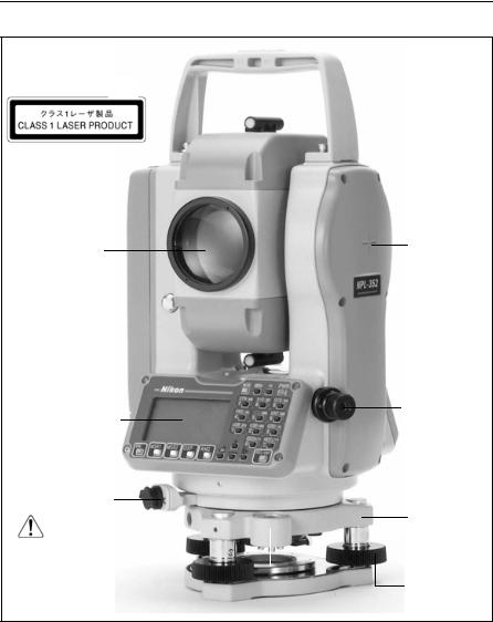
Parts of the Instrument
Figure 1.1 and Figure 1.2 show the main parts of the NPL-302 series instrument.
Carrying
handle
Optical sight (Finder)
Telescope focusing ring
Telescope
eyepiece
Diopter ring
Reticle plate cover
Plate level
Face-1 display/keyboard
Leveling base clamp knob
Battery mounting button
Battery pack
BC-65
Vertical tangent screw
Vertical clamp
Upper plate clamp
Upper plate tangent screw
The laser Safety Label shown below is attached to the underside of the keyboard
Figure 1.1 Pulse Laser Station NPL-302 series – Face-1
4 Pulse Laser Station NPL-302 Series Instruction Manual
Introduction 1
The Laser Class Label shown below is attached to the telescope
Objective
(LASER LIGHT IS EMITTED FROM THIS PART.)
Display and face-2 keyboard
(NPL-332 is not equipped with face-2 display/keyboard
Data output/ external power input connector
(Input voltage 7.2 – 11 V DC)
Circular level 
Horizontal axis indication mark
Optical plummet
Leveling base
Leveling screw
Figure 1.2 Pulse Laser Station NPL-302 series – Face-2
Pulse Laser Station NPL-302 Series Instruction Manual 5

1 Introduction
Maintenance
Before using the instrument, read and follow the following maintenance instructions:
•Do not leave the instrument in direct sunlight or in a closed vehicle for prolonged periods. Overheating the instrument may reduce its efficiency.
•If the NPL-302 series instrument has been used in wet conditions, immediately wipe off any moisture and dry the instrument completely before returning the instrument to the carrying case. The instrument contains sensitive electronic assemblies which have been well protected against dust and moisture. However, if dust or moisture gets into the instrument, severe damage could result.
•Sudden changes in temperature may cloud the lenses and drastically reduce the measurable distance, or cause an electrical system failure. If there has been a sudden change in temperature, leave the instrument in a closed carrying case in a warm location until the temperature of the instrument returns to room temperature.
•Do not store the NPL-302 series instrument in hot or humid locations. In particular, you must store the battery pack in a dry location at a temperature of less than 30 °C (86 °F). High temperature or excessive humidity can cause mold to grow on the lenses. It can also cause the electronic assemblies to deteriorate, and so lead to instrument failure.
•Store the battery pack with the battery discharged.
•When storing the instrument in areas subject to extremely low temperatures, leave the carrying case open.
•Do not overtighten any of the clamp screws.
•When adjusting the vertical tangent screws, upper plate tangent screws, or leveling screws, stay as close as possible to the center of each screw’s range. The center is indicated by a line on the screw. For final adjustment of tangent screws, rotate the screw clockwise.
•If the leveling base will not be used for an extended period, lock down the leveling base clamp knob and tighten its safety screw.
•Do not use organic solvents (such as ether or paint thinner) to clean the non-metallic parts of the instrument (such as the keyboard) or the painted or printed surfaces. Doing so could result in discoloration of the surface, or in peeling of printed characters. Clean these parts only with a soft cloth or a tissue, lightly moistened with water or a mild detergent.
6 Pulse Laser Station NPL-302 Series Instruction Manual
Introduction 1
•To clean the optical lenses, lightly wipe them with a soft cloth or a lens tissue that is moistened with alcohol.
•The reticle plate cover has been correctly mounted. Do not release it or subject it to excessive force to make it watertight.
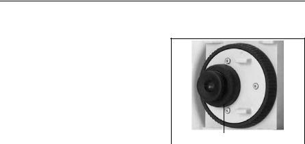
•Before attaching the battery pack, check that the contact surfaces on the battery and instrument are clean. Press the battery pack into place until the batterymounting button rises up to the battery
pack top surface. If the battery pack is not |
Reticle plate cover |
|
attached securely, the instrument is not |
||
|
||
|
||
watertight. |
|
•Press the cap that covers the data output/external power input connector terminal until it clicks into place. The instrument is not watertight if the cap is not attached securely, or when the data output/external power input connector is used.
•The carrying case is designed to be watertight, but you should not leave it exposed to rain for an extended period. If exposure to rain is unavoidable, make sure that the carrying case is placed with the Nikon nameplate facing upward.
•The BC-65 battery pack contains a Ni-MH battery. When disposing of the battery pack, follow the laws or rules of your municipal waste system.
•The instrument can be damaged by static electricity from the human body discharged through the data output/external power input connector. Before handling the instrument, touch any other conductive material once to remove static electricity.
Pulse Laser Station NPL-302 Series Instruction Manual 7

1 Introduction
8 Pulse Laser Station NPL-302 Series Instruction Manual

C H A P T E R
2
Preparation
In this chapter:
QUnpacking and Packing the Instrument
QCharging and Discharging the Battery Pack
QDetaching and Re-Attaching the Battery Pack
QSetting Up the Tripod
QCentering
QLeveling
QSighting
QSetting the Measurement Mode and Preparing the Target
QPreparing the Reflector Sheet
QSetting Up the Prism Reflector
QFace-1/Face-2 Measurements
Pulse Laser Station NPL-302 Series Instruction Manual 9
2 Preparation
Unpacking and Packing the Instrument
Note – Handle the NPL-302 series instrument gently to protect it from shocks and excessive vibration.
Unpacking
To unpack the instrument, grip the carrying handle and gently remove the instrument from the carrying case.
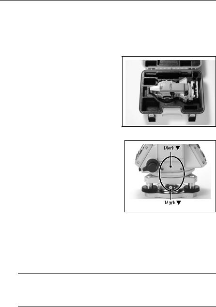
Packing
Note – Store the instrument with the battery pack attached.
To pack the instrument back into the carrying case:
1.Set the telescope in the horizontal face-1 position.
2.Align the W storage mark on the bottom of the face-1 keyboard with W the mark on the leveling base clamp knob.
3. Lightly fasten the clamp knobs.
4. Place the instrument in the carrying case.
Note – When packing the charger (Q-75U/E) in the plastic carrying case, make sure that you store it as shown on the sticker inside the case. Make sure that the battery charger cable is not pinched when you close the case cover.
Charging and Discharging the Battery Pack
Before charging the battery pack, read the warnings (also listed in the Safety section at the front of this manual) and the following notes.
C Warning – Use only the specified battery charger (part number Q-75U/E) to charge the battery pack (part number BC-65). Using other chargers, such as a charger with part number Q-7U/E or Q7C, may cause the battery pack to catch fire or rupture.
10 Pulse Laser Station NPL-302 Series Instruction Manual
Loading...