


N
Modulite Remote Control Set
ML-3
INSTRUCTION MANUAL
En

CONTENTS |
|
FOREWORD ..................................................... |
3 |
NOMENCLATURE ............................................ |
4–6 |
PREPARATION................................................. |
7–18 |
Transmitter |
|
Installing batteries and checking battery power.... |
7–9 |
Receiver |
|
Connecting the receiver to a camera................... |
10–11 |
Attaching receiver to bracket (optional) ............... |
11–12 |
Battery check.................................................... |
13–14 |
Positioning the transmitter and receiver ........... |
15–16 |
Distance range .................................................. |
17 |
Channel selector setting ................................... |
17 |
Camera settings ................................................ |
18 |
OPERATION ..................................................... |
18–29 |
Single frame shooting (S) .................................. |
19–20 |
Continuous frame shooting (C) ......................... |
21–22 |
Delay triggering ................................................. |
23–24 |
Auto triggering ................................................. |
25–28 |
Test mode ........................................................ |
25–26 |
Auto triggering operation ................................... |
26–28 |
Transmitter, receiver and camera indications... |
29 |
WIRELESS FLASH OPERATION...................... |
30–31 |
TIPS ON CARE ................................................. |
32–33 |
ABOUT BATTERIES ......................................... |
33 |
SPECIFICATIONS............................................. |
34–35 |
2

FOREWORD
Thank you for purchasing the Nikon Modulite Remote Control Set ML-3. The Nikon ML-3 combines a transmitter and receiver for the remote control of D3Series, D2-Series, D1-Series, D700, D300, D200, D100 + MB-D100, F6, F5, F100, F90X/N90s or F90Series/N90 camera by infrared ray. Its maximum effective range is 8m (26.2 ft.).
The ML-3 is designed so the transmission button operates the same way as the shutter release button on the camera. For example, lightly pressing the transmission button turns on the camera’s exposure meter and starts autofocus detection. Changeover from single to continuous shutter release can be accomplished directly from the transmitter and, when set, continuous release is activated by pressing the transmission button. The ML-3 also offers a delay mode that releases the shutter release approximately three seconds after you press the transmission button. Since two channels can be selected for signal transmission using the above-mentioned functions, two ML-3 units can be used in the same location, at the same time. Also, the shutter is released without pressing the transmission button when the subject crosses the point between the transmitter and the receiver which manually focuses in advance using the auto trigger function. This is especially convenient
when you want to take a picture, for example, of a small animal that is sensitive to human presence. When the transmitter of the ML-2 is used with the receiver of the ML-3, the maximum operating distance is extended to 100m away from the receiver, and a number of D3-Series, D2-Series, D1-Series, D700, D300, D200, D100 + MB-D100, F6, F5, F100, F90X/ N90s or F90-Series/N90 cameras can be operated simultaneously by using the ML-2’s ALL mode.
For optimum results, read this manual and the instruction manual of your camera thoroughly.
Infrared rays from the transmission head can cause eye damage. Do not look into the transmission head during transmission.
Notice for customers in the State of California
WARNING: Handling the cord on this product will expose you to lead, a chemical known to the State of California to cause birth defects or other reproductive harm. Wash hands after handling.
3
NOMENCLATURE
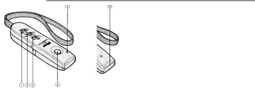
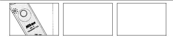
TRANSMITTER
1.Shooting mode selector: S for single-frame shooting, C for continuous shooting, D/T for delaying shutter release or checking transmitting conditions (with channel selector set to A. TRIG)
2.Channel selector (see page 17)
3.Power switch
4.Transmission button: Lightly press to transmit the signal that activates the camera’s exposure meter and autofocus functions; fully depress to transmit the signal that releases the shutter
5.Monitor light (battery check/transmission indicator LED): Lights up for a moment when power switch is set to ON or transmission button is lightly/fully pressed; blinks during A.TRIG operation or when battery power becomes weak
6.Wrist strap
7.Tripod socket
8.Transmission head: Do not cover or obstruct during transmission
9.Battery chamber: Accepts two AAA-type batteries (alkaline-manganese or manganese)
4
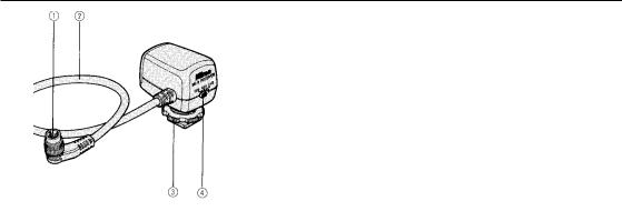
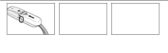
RECEIVER
1.Camera plug
2.Remote cord
3.Mounting foot lock screw: Be sure to tighten firmly when attaching receiver to the camera or bracket
4.Power/channel selector switch: OFF — power is off; for A. TRIG, CH1 and CH2, see page 14
5.External power socket for 6V power source (EIAJ RC-5320)
6.Reception sensor
7.Rotatable shoe foot: Rotates a full 360°
8.Reception indicator LED
5
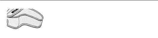
ACCESSORIES
Soft case (provided) |
Bracket (optional): For use when receiver cannot be |
|
mounted on the camera. |
6
PREPARATION
Transmitter
Installing batteries and checking battery power
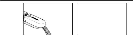
1.Open the battery chamber by sliding the battery chamber lid.
•Be sure the transmitter’s power switch is set to OFF position.
7
3.Close the battery lid by sliding it back into place.
4.Set power switch to ON.
If the monitor light comes on for a moment, batteries have sufficient power.
8
If it blinks, batteries may be weak.*
*Only with the channel selector set to CH1 or CH2.
If it does not come on, check battery installation or replace batteries with a fresh set.
5.Set the channel selector to CH1 or CH2.
9
Receiver
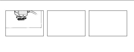
Connecting the receiver to a camera
1.Using gentle finger pressure, loosen the mounting foot lock screw (turn counterclockwise) as far as it goes without applying force.
2.While firmly holding the receiver, position the shoe foot to the camera’s accessory shoe and slide it in as far as it goes.
3.Using finger pressure only, gently but firmly tighten the lock screw
10
4.Insert the camera plug into the remote terminal of the camera with the D symbol on the plug aligning with the index mark on the camera. Then screw the threaded ring into the terminal.
Attaching receiver to bracket (optional)
When shooting with a Speedlight attached to the camera’s accessory shoe, attach the receiver by using the bracket.
11
 Loading...