


INC
FSA03701-R.3706.A
FSA03701
P A R T S L I S T
Copyrigh 2006 by Nikon Corporation. All Rights Reserved.
!!
Printed in Japan October 2006

|
A |
|
|
B |
INC |
|
|
|
FSA03701-R.3706.A |
||
|
|
|
|
|
|
|
|
|
|
1K010-816x2(10) |
|
|
1K001-349x4(10) |
|
|
1S700-643-1(1) |
|
|
|
|
|
|
|
|
|
|
|
|
1S700-643(1) |
|
|
83-537(5) |
|
|
|
|
1K220-661(5) |
|
|
|
1K010-482x2(10) |
|
|
1K087-588(10) |
|
|
|
1 |
1K220-660(5) |
|
|
|
|
1K087-587(10) |
|
|
|||
|
|
|
|||
|
H1-14040FA2(10) |
|
|
|
1S705-966(5) |
|
|
1S705-965(5) |
|
|
|
|
1S705-967(5) |
|
|
|
|
|
|
1K010-815(10) |
|
|
1K683-542(5) |
|
|
|
538(1) |
|
|
|
1K683-536(5) |
|
|
|
|
|
1K603-024(5) |
|
|
|
|
|
|
|
|
|
1K010-817x3 |
|
1K220-662x4(10) |
|
|
(10) |
|
|
|
|
1K683-540(5) |
||
|
1K360-259x4(10) |
1S700-644-1(1) |
|
||
|
|
|
|||
|
1S70 |
|
|
||
ST41-DF0152(5)
2
3
|
21(1) |
ST41-DF0154(5) |
41-660(5) |
|
ST41-DF0151 |
|
|
|
|
|
|
|
K241-661(5) |
|
(5) |
|
ST41-DF0153(5) |
|
|
|
|
|
|
|
|
|
|
1K010-816x2(10) |
|
|
|
1K68 |
|
1K104-643x2(5) |
|
|
|
|
|
1K104-6 |
|
|
|
|
|
1K241-658 |
|
|
|
|
|
|
||
|
1K010-815(10) |
|
(5) |
|
|
|
|
||
1K130-772(10) |
|
|
|
K201-465(5) |
1K683-543 |
|
|
|
|
1K233- |
|
|
01-466(5) |
|
|
|
|
|
1K660-320(1) |
1K120-536(10) |
|
|
-535(5) |
|
|
|
|
|
|
1K603-021(5) |
K120-536(10) |
|
60-447(5) |
|
|
|
|
||
|
241-659( |
|
|
|
ST41-DF0160(5) |
|
|
A03701-B1(1) |
|
|
ST41-DF0159(5) |
|
|
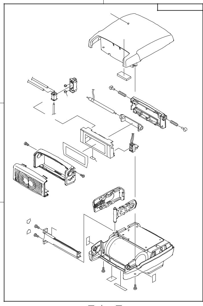
Fig. 1 |
CHANGE PAGE( × 2 |
F 1 SB-400 |
|
Dec.26.2006 |
|
|
|
|
|
|
|
|
A |
|
|
|
|
B |
INC |
|
|
|
|
|
|
|
||
|
|
|
|
|
|
A |
FSA03701-R.3706.A |
|
|
|
|
|
|
|
|
|
|
1 |
|
|
|
|
|
|
1K660-319(1) |
|
|
|
|
|
|
|
|
||
|
ST41-DF0156(5) |
1K683-529(5) |
1K104-116(5) |
|
|
|||
|
ST41-DF0155(5) |
|
|
|
|
|
|
|
|
ST41-0355(5) |
1K104-630x2(5) |
|
|
|
|||
|
|
|
|
|
|
|
1K660-317(1) |
|
|
|
|
|
|
ST41-0381(1) |
|
|
|
|
ST41-DF0161(5) |
|
|
|
|
|
1K220-659x2(5) |
|
|
|
FSA03701-D1(1) |
|
1K104-629(5) |
1K683-531x2(5) |
|||
|
|
|
|
|
|
|
||
|
1K010-815x2(10) |
|
|
|
|
|
|
|
2 |
|
|
|
|
|
|
FSA03701-C1(5) |
|
|
|
|
|
|
|
|
|
|
|
|
|
|
|
|
1K103-253(5) |
|
|
|
|
|
|
|
1K087-767(5) |
|
|
|
|
|
|
60 |
75 |
<![if ! IE]> <![endif]>90 |
|
|
|
|
|
45 |
|
|
|
|
||
|
|
|
|
1K467-291(5) |
|
|
||
|
|
|
|
|
|
|
||
|
|
1K660-316(1) |
|
|
||||
|
|
|
|
|
||||
|
1K660-318(5) |
|
|
|
|
FSA03701-A1(5) |
|
|
|
|
|
|
|
|
|
|
|
|
1K104-645x2(5) |
|
|
|
|
|
|
|
|
1K010-817x2(10) |
|
|
|
|
|
|
|
|
|
A |
|
|
|
|
|
|
3 |
1K683-541(5) |
|
|
|
|
|
Fig. 1 |
|
|
|
|
|
|
|
1K087-769(5) |
1K104-661x2(10) |
|
|
|
|
|
|
|
|
|
|
|
|
|
|
|
|
1K087-520(5) |
1K010-817x2(10) |
Fig. 2 |
|
|
|
|
|
|
|
||
|
|
|
|
|
|
|
|
|
|
|
|
|
|
|
F 2 SB-400 |
|
|

|
|
|
|
|
|
|
INC |
Parts List |
|
|
|
|
SB-400 |
|
|
|
|
|
|
|
FSA03701-R.3706.A |
||
Part Number |
Barcode (Part Code) |
|
Pcs,/ |
fig |
Main Assembly |
Q'ty/ |
Remarks |
Part Code |
|
Part Name |
Unit |
No. |
|
Order |
|
1K001-349
1K001-349
*1K010-482
1K010-482
1K010-815
1K010-815
1K010-816
1K010-816
1K010-817
1K010-817
*1K087-520
1K087-520
*1K087-587
1K087-587
*1K087-588
1K087-588
1K087-767
1K087-767
1K087-769
1K087-769
*1K103-253
1K103-253
*1K104-116
1K104-116
1K104-629
1K104-629
1K104-630
1K104-630
1K104-643
1K104-643
1K104-644
1K104-644
1K104-645
1K104-645
*1K001-349* |
|
4 |
1 |
10 |
SCREW |
||||
*1K010-482* |
SCREW |
2 |
1 |
10 |
SCREW |
||||
*1K010-815* |
|
4 |
1,2 |
10 |
SCREW |
||||
|
|
|||
*1K010-816* |
|
4 |
1 |
10 |
SCREW |
||||
|
|
|||
*1K010-817* |
|
7 |
1,2 |
10 |
SCREW |
||||
|
|
|||
*1K087-520* |
(CHINA) |
1 |
2 |
5 |
COUNTRY OF ORIGIN SEAL IV |
||||
|
|
|||
*1K087-587* |
(+) |
1 |
1 |
5 |
BATTERY SEAL (+) |
||||
|
|
|||
*1K087-588* |
(-) |
1 |
1 |
5 |
BATTERY SEAL (-) |
||||
*1K087-767* |
|
1 |
2 |
5 |
COVER PLATE |
||||
|
|
|||
*1K087-769* |
WEEE |
1 |
2 |
5 |
WEEE LABEL |
||||
|
|
|||
*1K103-253* |
|
1 |
2 |
5 |
TAPE |
||||
|
|
|||
*1K104-116* |
|
1 |
2 |
5 |
SPONGE |
||||
|
|
|||
*1K104-629* |
Xe |
1 |
2 |
5 |
Xe BAND |
||||
|
|
|||
*1K104-630* |
|
2 |
2 |
5 |
TRIGGER COIL RETAINER |
||||
*1K104-643* |
|
2 |
1 |
5 |
DRIP PROOF SPONGE |
||||
|
|
|||
*1K104-644* |
|
1 |
1 |
5 |
BOTH SIDED ADHESIVE TAPE |
||||
|
|
|||
*1K104-645* |
|
2 |
2 |
5 |
INSULATOR PLATE |
||||
|
|
- 1 -

|
|
|
|
|
|
|
INC |
Parts List |
|
|
|
|
SB-400 |
|
|
|
|
|
|
|
FSA03701-R.3706.A |
||
Part Number |
Barcode (Part Code) |
|
Pcs,/ |
fig |
Main Assembly |
Q'ty/ |
Remarks |
Part Code |
|
Part Name |
Unit |
No. |
|
Order |
|
1K104-661
1K104-661
1K120-536
1K120-536
1K130-772
1K130-772
1K201-465
1K201-465
1K201-466
1K201-466
1K220-659
1K220-659
1K220-660
1K220-660
1K220-661
1K220-661
1K220-662
1K220-662
1K233-286
1K233-286
1K241-658
1K241-658
1K241-659
1K241-659
1K241-660
1K241-660
1K241-661
1K241-661
*1K360-259
1K360-259
1K360-447
1K360-447
1K467-291
1K467-291
*1K104-661* |
|
2 |
2 |
10 |
|
TAPE |
|||||
*1K120-536* |
|
2 |
1 |
10 |
|
SCREW |
|||||
*1K130-772* |
|
1 |
1 |
10 |
|
SCREW |
|||||
|
|
||||
*1K201-465* |
|
1 |
1 |
5 |
|
POWER KNOB |
|||||
|
|
||||
*1K201-466* |
|
1 |
1 |
5 |
|
SHOE LOCK LEVER |
|||||
|
|
||||
*1K220-659* |
|
2 |
2 |
5 |
|
SPRING |
|||||
|
|
||||
*1K220-660* |
|
1 |
1 |
5 |
|
SPRING |
|||||
|
|
||||
*1K220-661* |
|
1 |
1 |
5 |
|
SHOE LOCK PIN SPRING |
|||||
*1K220-662* |
|
4 |
1 |
10 |
|
SHOE SPRING |
|||||
|
|
||||
*1K233-286* |
|
1 |
1 |
5 |
|
BOUNCE DETECTION LEVER SPRING |
|||||
|
|
||||
*1K241-658* |
SW |
1 |
1 |
5 |
|
POWER SW CLICK SPRING |
|||||
|
|
||||
*1K241-659* |
|
1 |
1 |
5 |
|
BOUNCE DETECTION CONTACT |
|||||
|
|
|
|||
*1K241-660* |
(+) |
1 |
1 |
5 |
|
BATTERY CONTACT (+) |
|||||
|
|
||||
*1K241-661* |
(-) |
1 |
1 |
5 |
|
BATTERY CONTACT (-) |
|||||
*1K360-259* |
|
4 |
1 |
10 |
|
CONTACT PIN |
|||||
|
|
||||
*1K360-447* |
|
1 |
1 |
5 |
|
SHOE LOCK PIN |
|||||
|
|
||||
*1K467-291* |
|
1 |
2 |
5 |
|
BATTERY OUTER COVER |
|||||
|
|
- 2 -

|
|
|
|
|
|
|
INC |
Parts List |
|
|
|
|
SB-400 |
|
|
|
|
|
|
|
FSA03701-R.3706.A |
||
Part Number |
Barcode (Part Code) |
|
Pcs,/ |
fig |
Main Assembly |
Q'ty/ |
Remarks |
Part Code |
|
Part Name |
Unit |
No. |
|
Order |
|
1K603-021
1K603-021
1K603-024
1K603-024
1K660-316
1K660-316
1K660-317
1K660-317
1K660-318
1K660-318
1K660-319
1K660-319
1K660-320
1K660-320
1K683-529
1K683-529
1K683-531
1K683-531
1K683-533
1K683-533
1K683-534
1K683-534
1K683-535
1K683-535
1K683-536
1K683-536
1K683-537
1K683-537
1K683-538
1K683-538
1K683-540
1K683-540
1K683-541
1K683-541
*1K603-021* |
( ) |
1 |
1 |
5 |
|
BOUNCE DETECTION CONTACT |
|||||
|
|
|
|||
*1K603-024* |
|
1 |
1 |
5 |
|
SPRING RETAINER PLATE |
|||||
*1K660-316* |
F |
1 |
2 |
1 |
|
F CASE |
|||||
|
|
||||
*1K660-317* |
R |
1 |
2 |
1 |
|
R CASE |
|||||
|
|
||||
*1K660-318* |
|
1 |
2 |
5 |
|
PROTECTOR |
|||||
|
|
||||
*1K660-319* |
U |
1 |
2 |
1 |
|
U CASE |
|||||
|
|
||||
*1K660-320* |
L |
1 |
1 |
1 |
|
L CASE |
|||||
|
|
||||
*1K683-529* |
|
1 |
2 |
5 |
|
TRIGGER COIL COVER |
|||||
*1K683-531* |
|
2 |
2 |
5 |
|
ROLLER |
|||||
|
|
||||
*1K683-533* |
READY |
1 |
1 |
5 |
|
READY WINDOW |
|||||
|
|
||||
*1K683-534* |
SW |
1 |
1 |
5 |
|
POWER SW FORK |
|||||
|
|
||||
*1K683-535* |
|
1 |
1 |
5 |
|
SHOE LOCK PIN MOLD |
|||||
|
|
||||
*1K683-536* |
|
1 |
1 |
5 |
|
SHOE LOCK LEVER SUPPORT |
|||||
|
|
||||
*1K683-537* |
|
1 |
1 |
5 |
|
SHOE LOCK SHAFT HOLDER |
|||||
*1K683-538* |
|
1 |
1 |
5 |
|
BATTERY CASE |
|||||
|
|
||||
*1K683-540* |
|
1 |
1 |
5 |
|
INVERSION STOPPER |
|||||
|
|
||||
*1K683-541* |
|
1 |
2 |
5 |
|
SEPARATOR |
|||||
|
|
- 3 -
|
|
|
|
|
|
|
|
|
INC |
|
Parts List |
|
|
|
|
SB-400 |
|
|
|
|
|
|
|
|
|
FSA03701-R.3706.A |
|||
|
Part Number |
|
Barcode (Part Code) |
|
Pcs,/ |
fig |
Main Assembly |
Q'ty/ |
Remarks |
|
Part Code |
|
|
Part Name |
Unit |
No. |
|
Order |
|
|
1K683-542 |
*1K683-542* |
|
1 |
1 |
|
5 |
|
|
|
1K683-542 |
BATTERY SPRING RETAINER |
|
|
|||||
|
|
|
|
|
|
|
|||
|
|
|
|
|
|
|
|
|
|
|
1K683-543 |
*1K683-543* |
|
1 |
1 |
|
5 |
|
|
|
1K683-543 |
BOUNCE DETECTION LEVER |
|
|
|||||
|
|
|
|
|
|
|
|||
|
|
|
|
|
|
|
|
|
|
|
1S700-643 |
*1S700-643* |
(PCB-L) |
1 |
1 |
|
1 |
OLD RP06121 |
|
|
1S700-643 |
PRINTED CIRCUIT UNIT L |
|
||||||
|
|
|
|
|
|
||||
|
|
|
|
|
|
|
|
|
|
|
1S700-643-1 |
*1S700-643-1* |
(PCB-L) |
1 |
1 |
|
1 |
NEW RP06121 |
|
1S700-643-1 |
PRINTED CIRCUIT UNIT L |
|
|||||||
|
1S700-644 |
*1S700-644* |
(PCB-H) |
1 |
1 |
|
1 |
OLD RP06121 |
|
|
1S700-644 |
PRINTED CIRCUIT UNIT H |
|
||||||
|
|
|
|
|
|
|
|
|
|
|
1S700-644-1 |
*1S700-644-1* |
(PCB-H) |
1 |
1 |
|
1 |
NEW RP06121 |
|
1S700-644-1 |
PRINTED CIRCUIT UNIT H |
|
|||||||
|
1S705-965 |
*1S705-965* |
FPC(FPC-F) |
1 |
1 |
|
5 |
|
|
|
1S705-965 |
SHOE FPC |
|
|
|||||
|
|
|
|
|
|
|
|||
|
|
|
|
|
|
|
|
|
|
|
1S705-966 |
*1S705-966* |
FPC (FPC-B) |
1 |
1 |
|
5 |
|
|
|
1S705-966 |
CONNECTION FPC |
|
|
|||||
|
|
|
|
|
|
|
|||
|
|
|
|
|
|
|
|
|
|
|
1S705-967 |
*1S705-967* |
GND (FPC-G) |
1 |
1 |
|
5 |
|
|
|
1S705-967 |
GND FPC |
|
|
|||||
|
|
|
|
|
|
|
|
|
|
|
FSA03701-A1 |
*FSA03701-A1* |
|
1 |
2 |
|
5 |
|
|
|
FSA03701-A1 |
BATTERY CONTACT UNIT |
|
|
|||||
|
|
|
|
|
|
|
|
|
|
|
FSA03701-B1 |
*FSA03701-B1* |
GND |
1 |
1 |
|
1 |
|
|
|
FSA03701-B1 |
GND UNIT |
|
|
|||||
|
|
|
|
|
|
|
|||
|
|
|
|
|
|
|
|
|
|
|
FSA03701-C1 |
*FSA03701-C1* |
SPD |
1 |
2 |
|
5 |
|
|
|
FSA03701-C1 |
SPD UNIT |
|
|
|||||
|
|
|
|
|
|
|
|||
|
|
|
|
|
|
|
|
|
|
|
FSA03701-D1 |
*FSA03701-D1* |
|
1 |
2 |
|
1 |
|
|
|
FSA03701-D1 |
REFLECTOR UNIT |
|
|
|||||
|
|
|
|
|
|
|
|||
|
|
|
|
|
|
|
|
|
|
|
H1-14040FA2 |
*H1-14040FA2* |
|
1 |
1 |
|
10 |
|
|
|
H1-14040FA2 |
SCREW |
|
|
|||||
|
|
|
|
|
|
|
|
|
|
|
ST41-0321 |
*ST41-0321* |
|
1 |
1 |
|
1 |
|
|
|
ST41-0321 |
MAIN CONDENSER |
|
|
|||||
|
|
|
|
|
|
|
|
|
|
|
ST41-0355 |
*ST41-0355* |
|
1 |
2 |
|
5 |
|
|
|
ST41-0355 |
TRIGGER COIL |
|
|
|||||
|
|
|
|
|
|
|
|||
|
|
|
|
|
|
|
|
|
|
|
ST41-0381 |
*ST41-0381* |
XE |
1 |
2 |
|
5 |
|
|
|
ST41-0381 |
XE TUBE |
|
|
|||||
|
|
|
|
|
|
|
|||
|
|
|
|
|
|
|
|
|
|
|
ST41-DF0151 |
*ST41-DF0151* |
( ) |
1 |
1 |
|
5 |
|
|
|
ST41-DF0151 |
CORD (RED) |
|
|
|||||
|
|
|
|
|
|
|
|||
|
|
|
|
|
|
|
|
|
|
|
ST41-DF0152 |
*ST41-DF0152* |
( ) |
1 |
1 |
|
5 |
|
|
|
ST41-DF0152 |
CORD (BLACK) |
|
|
|||||
|
|
|
|
|
|
|
|
|
|
|
CHANGE PAGE( ) x4 |
|
|
|
|
|
|
Dec. 26, 2006 |
|
- 4 -
|
|
|
|
|
|
|
INC |
Parts List |
|
|
|
|
SB-400 |
|
|
|
|
|
|
|
FSA03701-R.3706.A |
||
Part Number |
Barcode (Part Code) |
|
Pcs,/ |
fig |
Main Assembly |
Q'ty/ |
Remarks |
Part Code |
|
Part Name |
Unit |
No. |
|
Order |
|
ST41-DF0153 |
*ST41-DF0153* |
( ) |
1 |
1 |
|
5 |
|
ST41-DF0153 |
CORD (ORANGE) |
|
|
||||
|
|
|
|
|
|
|
|
ST41-DF0154 |
*ST41-DF0154* |
( ) |
1 |
1 |
|
5 |
|
ST41-DF0154 |
CORD (BLUE) |
|
|
||||
|
|
|
|
|
|
|
|
ST41-DF0155 |
*ST41-DF0155* |
( ) |
1 |
2 |
|
5 |
|
ST41-DF0155 |
CORD (BROWN) |
|
|
||||
|
|
|
|
|
|||
|
|
|
|
|
|
|
|
ST41-DF0156 |
*ST41-DF0156* |
( ) |
1 |
2 |
|
5 |
|
ST41-DF0156 |
CORD (WHITE) |
|
|
||||
|
|
|
|
|
|||
|
|
|
|
|
|
|
|
ST41-DF0159 |
*ST41-DF0159* |
( ) |
1 |
1 |
|
5 |
|
ST41-DF0159 |
CORD (BLACK) |
|
|
||||
|
|
|
|
|
|||
|
|
|
|
|
|
|
|
ST41-DF0160 |
*ST41-DF0160* |
( ) |
1 |
1 |
|
5 |
|
ST41-DF0160 |
CORD (BROWN) |
|
|
||||
|
|
|
|
|
|||
|
|
|
|
|
|
|
|
ST41-DF0161 |
*ST41-DF0161* |
( ) |
1 |
2 |
|
5 |
|
ST41-DF0161 |
CORD (WHITE) |
|
|
||||
|
|
|
|
|
|||
|
|
|
|
|
|
|
|
|
|
|
|
|
|
|
|
|
|
|
|
|
|
|
|
|
|
|
|
|
|
|
|
|
|
|
|
|
|
|
|
|
|
|
|
|
|
|
|
|
|
|
|
|
|
|
|
|
|
|
|
|
|
|
|
|
|
|
|
|
|
|
|
|
|
|
|
|
|
|
|
|
|
|
|
|
|
|
|
|
|
|
|
|
|
|
|
|
|
|
|
|
|
|
|
- 5 -
INC
FSA03701-R.3706.A

FSA0370
REPAIR MANUAL
Copyrigh  2006 by Nikon Corporation All Rights Reserved
!!
Printed in Japan November 2006
|
INC |
|
FSA03701-R.3706.A |
|
Specifications |
Electronic construction |
Automatic Insulated Gate Bipolar Transistor (IGBT) and series circuitry |
Guide number (at |
30/98.4 (ISO200, m/ft), 21/69 (ISO100, m/ft) |
18 mm zoom head |
|
position, 20°C/68°F) |
|
Angle of coverage |
Light distribution covers an 18mm lens when mounted on a Nikon DX format |
|
camera, and a 27mm lens when mounted on an F6 |
Flash shooting |
0.6m to 20m (2 to 66 ft.)(varies depending on the ISO sensitivity, angle of the flash |
distance range |
head, and lens aperture in use) |
Flash mode |
i-TTL, M (manual, only with the D40) |
Compatible cameras |
All cameras compatible with CLS |
Flash exposure control |
Slow-sync, Red-eye reduction, Red-eye reduction in slow-sync, Rear-curtain sync |
set on the camera |
flash, FV Lock flash, manual flash |
|
|
Bounce capability |
Flash head tilts up to 90°with click-stops at 0°, 60°, 75°, 90° |
ON/OFF switch |
Turn the SB-400 on and off using the ON/OFF switch |
Power source/min. |
TwoAA-type penlight batteries (1.5V or lower) of any types |
recycling time/no. of |
|
flashes (at full output) |
|
With fresh batteries |
|
(These data may vary |
|
depending on battery |
|
condition) |
|
|
250/4.2 - 30 sec |
|
3.1 sec |
Ready-light
Flash duration (approx.)
Mounting foot lever lock
Dimensions
(W × H ×D)
Weight (without batteries)
Included accessories
When firing the Speedlight at full output once every 30 seconds (120 seconds with lithium batteries)
Lights up when the SB-400 is recharged and ready to fire
Blinks to indicate: insufficient light/insufficient battery power/incompatibility of camera with SB-400/overheating
1/1300 sec. at full output
Provides secure attachment of SB-400 to camera's accessory shoe using mount pin to prevent accidental detachment
Approx. 66.×56.5×80 mm (2.6 ×2.2 × 3.1 in.)
Approx. 127g (4.5 oz.)
SS-400 Soft Case
- M1 SB-400 -
INC
FSA3701-R.3706.A
Disassembly
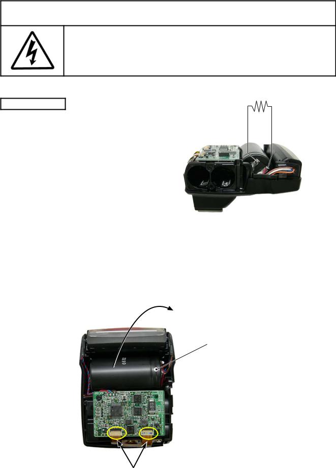
 WARNING
● Due to an internal high voltage area, be sure to discharge the main condenser before removing covers according to the instructions of the repair manuals.
Note) Lead-free solder is used all for this product.
U-CASE
Open the battery lid, and remove the two insulating plates (#65).
Take out the two screws (#82).
Insulating Plate #65×2
#82×2 |
Battery Cover |
Take out the two screws (#82). |
#82×2 |
|
Remove the U-case (#21).
The battery lid comes off. |
U-Case (#21) |
|
Battery Cover
- D SB-400 -
INC
FSA3701-R.3706.A
 WARNING
● Due to an internal high voltage area, be sure to discharge the main condenser before removing covers according to the instructions of the repair manuals.
200Ω 1KΩ
DISCHARGE
Discharge the main condenser.
Disconnect the two FPCs from the connector.Remove the main condenser.
The main condenser is fixed with the adhesive double-coated tape.
Main Condenser
× 2
- D SB-400 -
INC
FSA3701-R.3706.A
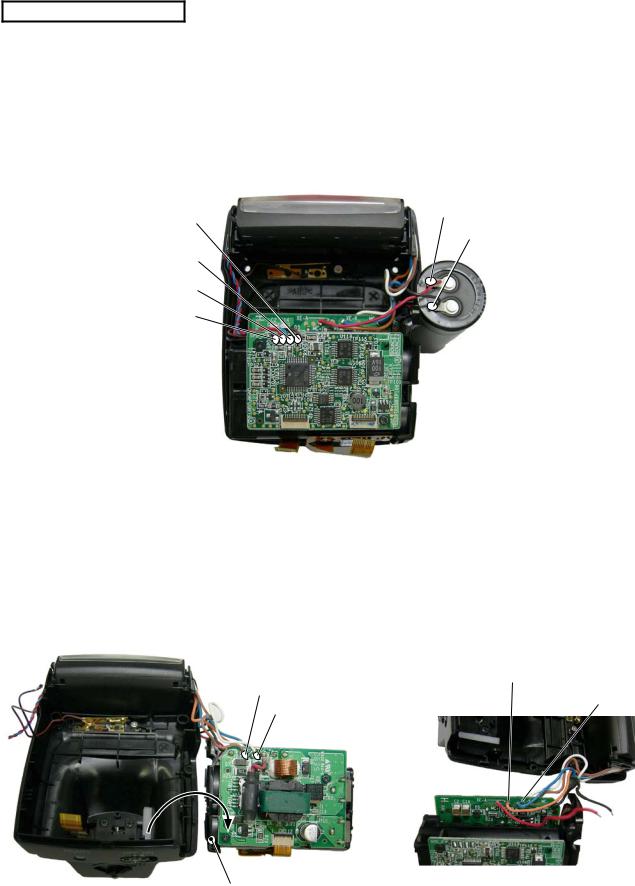
MAIN CONDENSER
Remove the wires (red and black) connected from the main condenser.
Remove the four (brown, black, blue, and red) wires connected from the SPD unit and bounce SW.
Bounce SW : Brown
Main condenser :Red
Main condenser :Black
Bounce SW : Black
SPD unit : Blue
SPD unit : Red
Remove the battery case unit from the body.
Remove the wires (brown and white) connected from the trigger coil.Remove the wires (orange and blue) connected from the Xe-tube.
Xe Tube : Orange
Trigger coil : Brown
Xe Tube : Blue
Trigger coil : White
Battery case unit
- D SB-400 -
INC
FSA3701-R.3706.A
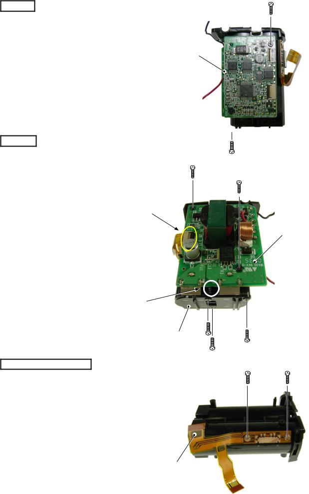
L-PCB |
#81×2 |
Take out the two screws (#81).
Remove the L/low-voltage PCB (#97).
L-PCB (#97)
H-PCB
Disconnect the connector. |
#81×2 |
Take out the three screws (#82). |
|
Remove the battery spring retainer (#64). |
|
|
Connector |
Take out the two screws (#81).
While releasing the hook of the battery case, remove the H/high-voltage PCB (#98).
Hook
Battery spring retainer (#64)
BATTERY CASE UNIT
#87×2
Take out the two screws (#87).Remove the connection-FPC (#96).
H-PCB (#98)
#82×3
Connection-FPC (#96)
Battery case unit
- D SB-400 -
 Loading...