


En
Fr
1.5-4.5×20 / 3×32 / 3-9×40 / 4-12×40
Instruction manual/Mode d'emploi

|
|
Congratulations on your choice of a Nikon riflescope. Your new scope is the finest example of Nikon’s rugged and durable construction and precision bright optics; important qualities for a serious shooter’s riflescope. |
|
|
Whether you use your scope for target shooting or for hunting, the procedure for mounting is identical. A set of high-quality steel mounting rings which have a standard diameter of 1 in. (25.4 mm) are required to mount |
En |
||
|
|
the scope. Follow the ring manufacturer’s instructions for mounting procedures. After mounting the scope on your rifle, follow the procedures for reticle alignment. |
|
|
|
|
|
WARNING: |
|
|
IMPROPER MOUNTING OF YOUR NIKON SCOPE CAN CAUSE SERIOUS INJURY. |
|
|
THUS IT IS IMPORTANT THAT YOUR NIKON SCOPE IS MOUNTED PROPERLY BEFORE USING. TO ENSURE PROPER MOUNTING OF YOUR NIKON SCOPE, PLEASE HAVE IT MOUNTED AND/OR CHECKED BY AN EXPERIENCED |
|
|
GUNSMITH BEFORE USING. |
|
|
THE USER ASSUMES ALL RESPONSIBILITY AND LIABILITY FOR HAVING THE SCOPE PROPERLY MOUNTED TO A FIREARM AND FOR USING THE SCOPE PROPERLY. |
|
|
ALWAYS CHECK THE CONDITION OF YOUR SCOPE AND YOUR MOUNTING SYSTEM BEFORE USING YOUR FIREARM. |
|
|
|
|
|
SUPPLIED ITEM(S) |
|
|
Body·························································· 1 piece |
|
|
Eyepiece cap············ |
|
|
Objective cap············································ 1 pair* |
|
*Rubber band linked (This type connects the objective and eyepiece caps using a rubber band.) |
|
2

Caution |
|
|
En |
||
(1) Do NOT look at the sun through the riflescope. It will permanently damage your eye. This precaution applies to all optical devices, such as cameras and binoculars. |
||
|
(2)The riflescope is effectively sealed against moisture and dust. You may use your scope safely either in the rain or in dusty climates. To preserve the appearance of the scope, we recommend that it be dried and cleaned prior to storage. Use a soft cloth for cleaning metal surfaces and use photographic lens tissue to clean the scope’s lenses.
Notice for customers in the State of California
WARNING: This product contains chemicals including Lead which is known to the State of California to cause cancer and birth defects or other reproductive harm. For more information go to  www.P65Warnings.ca.gov.
When setting the reticle for shooting or hunting, you should determine your standard range and then adjust the reticle based upon that target distance. For targets which vary from that standard distance, according to personal preference, you may simply adjust the position of the reticle in relation to your target, or you may wish to use the procedure for trajectory compensation.
We hope that you will enjoy your new Nikon Riflescope for many years to come. Enjoy using it, and above all, always follow safe shooting procedures.
N.B. Export of the products* in this manual may be controlled under the laws and relatives of the exporting country. Appropriate export procedure, such as obtaining of export license, shall be required in case of export. *Products: Hardware and its technical information (including software)
3

|
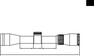
1. Nomenclature |
|
|
En |
• 1.5-4.5×20 |
|
|
|
|
|
5 |
|
|
|
. |
|
|
|
2 |
|
|
|
<![if ! IE]> <![endif]>3 |
|
|
|
5 |
|
|
|
. |
|
|
|
3 |
|
|
Fig. 1-1 |
4 |
|
|
|
|
|
1Objective lens |
6Power index* |
|
|
2Eyepiece lens |
7Power scale* |
|
|
3Elevation adjustment turret |
8Power selector ring* |
|
|
4Windage adjustment turret |
9Diopter index dot |
|
|
5Eyepiece adjustment |
*1.5-4.5×20, 3-9×40 and 4-12×40 only |
|
• 3×32
• 3-9×40 |
Fig. 1-2 |
|
|
• 4-12×40 |
|
Fig. 1-3
<![endif]>9 8 7 6 5
4
2. Specifications
Model |
|
|
1.5-4.5×20 |
3×32 |
3-9×40 |
4-12×40 |
Actual magnification |
(×) |
|
1.5-4.5 |
3 |
3-9 |
4-12 |
Effective objective diameter |
(mm) |
|
20 |
32 |
40 |
40 |
Exit pupil |
(mm) |
|
13.3-4.4*1 |
10.7 |
13.3-4.4*1 |
10.0-3.3*1 |
Eye relief |
(in.)/(mm) |
|
3.5-3.5/88.9-88.9*1 |
3.4/87 |
3.6-3.6/91.5-91.5*1 |
3.7-3.7/94.0-94.0*1 |
Tube diameter |
(in.)/(mm) |
|
1/25.4 |
1/25.4 |
1/25.4 |
1/25.4 |
Objective outside diameter |
(in.)/(mm) |
|
1/25.4 |
1.6/40.5 |
1.9/48.8 |
1.9/48.8 |
Eyepiece outside diameter |
(in.)/(mm) |
|
1.7/44 |
1.6/41 |
1.7/44 |
1.7/44 |
Adjustment graduation |
|
|
1 click: 1/4 MOA*2 |
1 click: 1/4 MOA*2 |
1 click: 1/4 MOA*2 |
1 click: 1/4 MOA*2 |
|
|
|
1 revolution: 20 MOA*2 |
1 revolution: 20 MOA*2 |
1 revolution: 20 MOA*2 |
1 revolution: 20 MOA*2 |
|
|
|
1 revolution: 80 clicks |
1 revolution: 80 clicks |
1 revolution: 80 clicks |
1 revolution: 80 clicks |
Max. internal adjustment |
(MOA)*2 |
|
150 |
130 |
75 |
55 |
Parallax setting |
(yd.)/(m) |
|
100/91.4 |
100/91.4 |
100/91.4 |
100/91.4 |
Field of view at 100 yd. |
(ft) |
|
63.1-20.4*1 |
35.6 |
33.5-11.5*1 |
23.6-7.9*1 |
Field of view at 100 m |
(m) |
|
21.0-6.8*1 |
11.9 |
11.2-3.8*1 |
7.9-2.6*1 |
Length (a) |
(in.)/(mm) |
|
10.2/258.0 |
8.2/209.0 |
12.4/315 |
14.1/358 |
Mount length (b) |
(in.)/(mm) |
|
2.9/73.6 |
1.2/29.6 |
2.0/50.6 |
2.5/63.5 |
Mount length (c) |
(in.)/(mm) |
|
1.3/33.0 |
1.3/33.0 |
1.3/33.0 |
1.3/33.0 |
Mount length (d) |
(in.)/(mm) |
|
2.1/53.0 |
1.1/28.3 |
2.1/53.0 |
2.1/53.0 |
Weight |
(oz)/(g) |
|
14.8/420 |
12.7/360 |
16.9/480 |
17.5/495 |
Structure |
|
|
|
Waterproof (up to 3 ft 3 in. (1 m) for 10 minutes) and nitrogen gas purged |
|
|
*1 (at minimum magnification)-(at maximum magnification) |
*2 MOA = Minute of Angle |
|
|
|
||
En
Objective Eyepiece
b |
c |
d |
|
a |
|
Letters a to d in the diagram above refer to lengths (a) to (d) shown in the Specifications table.
5
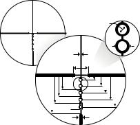
Reticle subtension chart
En |
• BDC 600 reticle (for 1.5-4.5×20 only) |
|
|
C |
|
|
D |
|
A |
|
|
|
B |
|
|
F |
|
H |
G |
|
I |
|
|
J |
|
|
K |
|
N L |
|
|
E |
M |
|
|
|
O |
Letters A to O in the diagram above refer to the reticle subtensions of units A to O shown on the table to the right.
|
|
Model |
|
|
|
1.5-4.5×20 |
|
|
|
Reticle |
|
|
|
|
BDC 600 |
|
|
||
Magnification (×) |
1.5 |
|
|
|
4.5 |
||||
|
|
Unit |
(in.) |
|
(cm) |
|
(in.) |
|
(cm) |
|
|
A |
1.50 |
|
4.17 |
|
0.50 |
|
1.39 |
| <![if ! IE]> <![endif]>yards) |
|
B |
24.00 |
|
66.72 |
|
8.00 |
|
22.24 |
| <![if ! IE]> <![endif]>at 100 |
|
C |
3.00 |
|
8.34 |
|
1.00 |
|
2.78 |
|
D |
6.00 |
|
16.68 |
|
2.00 |
|
5.56 |
|
| <![if ! IE]> <![endif]>metres/inches |
|
|
|
|
|||||
|
E |
3.00 |
|
8.34 |
|
1.00 |
|
2.78 |
|
|
|
|
|
|
|||||
|
|
F |
4.50 |
|
12.51 |
|
1.50 |
|
4.17 |
| <![if ! IE]> <![endif]>at 100 |
|
G |
11.25 |
|
31.28 |
|
3.75 |
|
10.43 |
|
H |
15.00 |
|
41.70 |
|
5.00 |
|
13.90 |
|
| <![if ! IE]> <![endif]>(cm |
|
I |
19.50 |
|
54.21 |
|
6.50 |
|
18.07 |
| <![if ! IE]> <![endif]>subtensions |
|
J |
24.75 |
|
68.81 |
|
8.25 |
|
22.94 |
|
|
K |
30.75 |
|
85.49 |
|
10.25 |
|
28.50 |
| <![if ! IE]> <![endif]>Reticle |
|
L |
37.50 |
|
104.25 |
|
12.50 |
|
34.75 |
|
M |
44.25 |
|
123.02 |
|
14.75 |
|
41.01 |
|
|
|
N |
51.00 |
|
141.78 |
|
17.00 |
|
47.26 |
|
|
O |
3.00 |
|
8.34 |
|
1.00 |
|
2.78 |
6
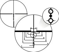
• BDC 600 reticle (for 3-9×40 and 4-12×40)
C
D
A

B
G |
F |
|
H |
||
I |
||
J |
||
K |
||
L |
||
O M E |
||
N |


 P
P
Letters A to P in the diagram above refer to the reticle subtensions of units A to P shown on the table to the right.
|
|
|
|
|
|
|
|
|
|
|
|
|
|
|
|
En |
||
|
|
Model |
|
|
|
3-9×40 |
|
|
|
|
|
4-12×40 |
|
|
|
|||
Reticle |
|
|
|
|
BDC 600 |
|
|
|
|
|
BDC 600 |
|
|
|
|
|||
Magnification (×) |
|
3 |
|
|
9 |
|
4 |
|
|
12 |
|
|
||||||
|
|
Unit |
(in.) |
|
(cm) |
|
(in.) |
|
(cm) |
(in.) |
|
(cm) |
|
(in.) |
|
(cm) |
|
|
|
|
A |
0.75 |
|
2.09 |
|
0.25 |
|
0.70 |
0.75 |
|
2.09 |
|
0.25 |
|
0.70 |
|
|
| <![if ! IE]> <![endif]>yards) |
|
B |
24.00 |
|
66.72 |
|
8.00 |
|
22.24 |
24.00 |
|
66.72 |
|
8.00 |
|
22.24 |
|
|
|
C |
1.50 |
|
4.17 |
|
0.50 |
|
1.39 |
1.50 |
|
4.17 |
|
0.50 |
|
1.39 |
|
|
|
| <![if ! IE]> <![endif]>100 |
|
D |
3.00 |
|
8.34 |
|
1.00 |
|
2.78 |
3.00 |
|
8.34 |
|
1.00 |
|
2.78 |
|
|
| <![if ! IE]> <![endif]>at |
|
|
|
|
|
|
|
|
|
|||||||||
| <![if ! IE]> <![endif]>metres/inches100 |
|
E |
2.25 |
|
6.26 |
|
0.75 |
|
2.09 |
2.25 |
|
6.26 |
|
0.75 |
|
2.09 |
|
|
|
H |
11.25 |
|
31.28 |
|
3.75 |
|
10.43 |
11.25 |
|
31.28 |
|
3.75 |
|
10.43 |
|
|
|
|
|
F |
4.50 |
|
12.51 |
|
1.50 |
|
4.17 |
4.50 |
|
12.51 |
|
1.50 |
|
4.17 |
|
|
|
|
G |
7.50 |
|
20.85 |
|
2.50 |
|
6.95 |
7.50 |
|
20.85 |
|
2.50 |
|
6.95 |
|
|
| <![if ! IE]> <![endif]>at |
|
|
|
|
|
|
|
|
|
|
|
|
|
|
|
|
|
|
|
I |
15.00 |
|
41.70 |
|
5.00 |
|
13.90 |
15.00 |
|
41.70 |
|
5.00 |
|
13.90 |
|
|
|
| <![if ! IE]> <![endif]>(cm |
|
|
|
|
|
|
|
|
|
|||||||||
|
J |
19.50 |
|
54.21 |
|
6.50 |
|
18.07 |
19.50 |
|
54.21 |
|
6.50 |
|
18.07 |
|
|
|
| <![if ! IE]> <![endif]>subtensions |
|
|
|
|
|
|
|
|
|
|||||||||
|
L |
30.75 |
|
85.49 |
|
10.25 |
|
28.50 |
30.75 |
|
85.49 |
|
10.25 |
|
28.50 |
|
|
|
|
|
K |
24.75 |
|
68.81 |
|
8.25 |
|
22.94 |
24.75 |
|
68.81 |
|
8.25 |
|
22.94 |
|
|
| <![if ! IE]> <![endif]>Reticle |
|
|
|
|
|
|
|
|
|
|
|
|
|
|
|
|
|
|
|
M |
37.50 |
|
104.25 |
|
12.50 |
|
34.75 |
37.50 |
|
104.25 |
|
12.50 |
|
34.75 |
|
|
|
|
|
|
|
|
|
|
|
|
|
|||||||||
|
|
N |
44.25 |
|
123.02 |
|
14.75 |
|
41.01 |
44.25 |
|
123.02 |
|
14.75 |
|
41.01 |
|
|
|
|
O |
51.00 |
|
141.78 |
|
17.00 |
|
47.26 |
51.00 |
|
141.78 |
|
17.00 |
|
47.26 |
|
|
|
|
P |
3.00 |
|
8.34 |
|
1.00 |
|
2.78 |
3.00 |
|
8.34 |
|
1.00 |
|
2.78 |
|
|
7
En |
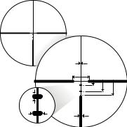
• BDC Carbine reticle |
|
A |
|
B |
|
E |
|
F |
|
G |
|
C |
D |
H |
|
Letters A to H in the diagram above refer to the reticle subtensions of units A to H shown on the table to the right.
|
|
Model |
|
3×32 |
|
Reticle |
|
|
BDC Carbine |
||
Magnification (×) |
|
3 |
|||
| <![if ! IE]> <![endif]>metres/ |
|
Unit |
(in.) |
|
(cm) |
|
A |
1.00 |
|
2.78 |
|
| <![if ! IE]> <![endif]>subtensions (cm at 100 inches at 100 yards) |
|
B |
24.00 |
|
66.72 |
|
C |
1.00 |
|
2.78 |
|
|
D |
3.40 |
|
9.45 |
|
|
E |
5.50 |
|
15.29 |
|
|
F |
14.25 |
|
39.62 |
|
| <![if ! IE]> <![endif]>Reticle |
|
G |
20.00 |
|
55.60 |
|
H |
3.00 |
|
8.34 |
|
|
|
|
|||
8
3. Instructions
(1)Focusing
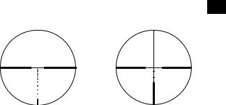
1Look through the eyepiece with your eye positioned about 4 in. (10 cm) away from the eyepiece to see the BDC 600 reticle (Fig. 3-1) or the BDC Carbine reticle (Fig. 3-2).
Be sure your eye is positioned with proper alignment and with proper eye relief, otherwise the view will“black out.”
2Point the objective end of the scope at the sky (do NOT point it at the sun) or at a plain unpatterned wall.
3Turn the eyepiece adjustment counter-clockwise and then turn it clockwise until the reticle appears sharp.
Notice: Reticle images shown in this manual are representation only. Actual images may vary.
En
BDC 600 reticle |
BDC Carbine reticle |
Fig. 3-1 |
Fig. 3-2 |
9

(2) Magnification
En •The P-TACTICAL .223 riflescopes have fixed or variable magnification. For details, see“2. Specifications”.
To change powers (1.5-4.5×20, 3-9×40 and 4-12×40 only), rotate the power selector ring until the desired magnification appears adjacent to the power index.
(3) Adjustment of the riflescope
Sighting through the riflescope, align the rifle with your aiming point on the target and shoot a trial round. If the bullet does not hit the aiming point, adjust the elevation and windage adjustment turrets as follows:
•If the bullet hits under the aiming point, turn the elevation adjustment turret (counter-clockwise) in the direction of the arrow marked“U” for up. If the bullet hits high, turn the elevation adjustment turret (clockwise) in the direction of the arrow marked“D” for down.
•If the bullet hits to the right of the aiming point, turn the windage adjustment turret (clockwise) in the direction of the arrow marked“L” for left. If the bullet hits to the left of the aiming point, turn the windage adjustment turret (counter-clockwise) in the direction of the arrow marked“R” for right.
Note:
•The windage and elevation scales of P-TACTICAL .223 riflescopes are calibrated in divisions of 1/4 minute of angle (MOA) with a click at intervals of 1/4 minute of angle.
•When adjusting the reticle to the point of aim, remember that 1 minute of angle equals approximately 1 in. (2.54 cm) at 100 yd. (91.44 m).
Therefore, if the impact point is 2 in. (5.08 cm) low and 1 in. (2.54 cm) right at 100 yd. (91.44 m) parallax setting, you should adjust 2 minutes of angle up and 1 minute of angle left. In the case of 50 yd. (45.72 m) parallax setting, the adjusting value is 2×. In the case of 75 yd. (68.58 m) parallax setting, the adjusting value is 1.5×.
10
(4) Zero resetting of adjustment turret
The elevation adjustment and windage adjustment turrets have a retracting system. After the reticle has been adjusted to match the point of impact, pull up the elevation adjustment or windage adjustment turret En to disengage. The turret can now be turned freely. Align the zero number to the index line to set the zero setting, and then release the turret. The turret automatically retracts to the original position.
11
 Loading...