

Page 1
Series FEC Environmental Chamber
Manual Title
Additional Information
Product Manual
be certain.
100-231-448 A
Page 2

Copyright information © 2011 MTS Systems Corporation. All rights reserved.
Trademark information MTS is a registered trademark and MTS Criterion and MTS Insight are
trademarks of MTS Systems Corporation within the United States. These
trademarks may be protected in other countries.
Publication information
MANUAL PART NUMBER PUBLICATION DATE
100-231-448 A December 2011
2
Series FEC Environmental Chamber Product Manual
Page 3

Contents
Preface 5
Before You Begin 5
Conventions 6
Documentation Conventions 6
Technical Support 9
How to Get Technical Support 9
Before You Contact MTS Service Representative 9
If You Contact MTS by Phone 10
Introduction 13
About This Manual 13
Inappropriate Use 13
Description 14
Specifications 16
Operating Condition Requirements 16
Model and Specifications 16
Safety Information 17
Safety 17
Hazard Placard Placement 17
Installation 19
Installing Bracket of Environmental Chamber 20
Installing Environmental Chamber 22
Adjusting Environmental Chamber Position 24
Connecting Environmental Chamber Mains Power 26
Connecting Liquid Nitrogen to the Chamber 27
Prerequisites 27
Connecting an LN2 supply tank to the chamber: 27
Series FEC Environmental Chamber Product Manual Contents
3
Page 4

Operation 29
Installing Pull Rods and Grips 30
Operation of Temperature Controller 31
Temperature Controller Common Functions 35
Test Case 40
Routine Maintenance 43
Routine Maintenance Overview Checklist 43
Troubleshooting 44
Declaration of Conformity 45
4
Contents
Series FEC Environmental Chamber Product Manual
Page 5

Before You Begin
Preface
Before You Begin
Safety first! Before you use your MTS product or system, read and understand the safety
information provided with your system. Improper installation, operation, or
maintenance can result in hazardous conditions that can cause severe personal
injury or death, or damage to your equipment and specimen. Again, read and
understand the safety information provided with your system before you
continue. It is very important that you remain aware of hazards that apply to your
system.
Other MTS manuals In addition to this manual, you may receive additional manuals in paper or
electronic form.
Manuals located on the product information CD will contain information that
pertains to your test system, such as:
• Hydraulic and/or mechanical accessory manuals
• Assembly drawings
• Parts lists
• Operation instructions
• Preventive maintenance tasks
Controller and application software manuals are typically included on the
software CD distribution disc(s).
Series FEC Environmental Chamber Product Manual Preface
5
Page 6

Conventions
Conventions
Documentation Conventions
The following paragraphs describe some of the conventions that are used in your
MTS manuals.
Hazard conventions Hazard notices may be embedded in this manual. These notices contain safety
information that is specific to the activity to be performed. Hazard notices
immediately precede the step or procedure that may lead to an associated hazard.
Read all hazard notices carefully and follow all directions and recommendations.
Three different levels of hazard notices may appear in your manuals. Following
are examples of all three levels.
DANGER
Danger notices indicate the presence of a hazard with a high level of risk which,
if ignored, will result in death, severe personal injury, or substantial property
damage.
WARNING
Warning notices indicate the presence of a hazard with a medium level of risk
which, if ignored, can result in death, severe personal injury, or substantial
property damage.
CAUTION
Caution notices indicate the presence of a hazard with a low level of risk which,
if ignored, could cause moderate or minor personal injury or equipment damage,
or could endanger test integrity.
Notes Notes provide additional information about operating your system or highlight
easily overlooked items. For example:
Note Resources that are put back on the hardware lists show up at the end of
the list.
Special terms The first occurrence of special terms is shown in italics.
Illustrations Illustrations appear in this manual to clarify text. They are examples only and do
not necessarily represent your actual system configuration, test application, or
software.
Electronic manual
conventions
This manual is available as an electronic document in the Portable Document
File (PDF) format. It can be viewed on any computer that has Adobe Acrobat
Reader installed.
Preface
6
Series FEC Environmental Chamber Product Manual
Page 7

Documentation Conventions
Hypertext links The electronic document has many hypertext links displayed in a blue font. All
blue words in the body text, along with all contents entries and index page
numbers, are hypertext links. When you click a hypertext link, the application
jumps to the corresponding topic.
Series FEC Environmental Chamber Product Manual Preface
7
Page 8

Page 9

Technical Support
How to Get Technical Support
How to Get Technical Support
Start with your
manuals
Technical support
methods
The manuals supplied by MTS provide most of the information you need to use
and maintain your equipment. If your equipment includes software, look for
online help and README files that contain additional product inform ation.
If you cannot find answers to your technical questions from these sources, you
can use the Internet, e-mail, telephone, or fax to contact MTS for assistance.
MTS provides a full range of support services after your system is installed. If
you have any questions about a system or product, contact Technical Support in
one of the following ways.
Outside the U.S. For technical support outside the United States, contact your local sales and
service office. For a list of worldwide sales and service locations and contact
information, use the Global MTS link at the MTS web site:
www.mts.com > Global MTS > (choose your region in the right-hand
column) > (choose the location closest to you)
Before You Contact MTS Service Representative
MTS can help you more efficiently if you have the following information
available when you contact us for support.
Know your contact
number and system
number
The contact number contains your company number and identifies your
equipment type (such as material testing or simulation). The number is typically
written on a label on your equipment before the system leaves MTS. If you do
not know your MTS contact number, contact your sales engineer.
When you have more than one MTS system, the system model number and series
number identifies your system. You can find your these number in your order
paperwork or directly on your equipment.
Identify the problem Describe the problem and know the answers to the following questions:
• How long and how often has the problem occurred?
• Can you reproduce the problem?
• Were any hardware or software changes made to the system before the
problem started?
• What are the equipment model numbers?
• What is the controller model (if applicable)?
• What is the system configuration?
Series FEC Environmental Chamber Product Manual Technical Support
9
Page 10

If You Contact MTS by Phone
Know relevant
computer information
Know relevant
software information
For a computer problem, have the following information available:
• Manufacturer’s name and model number
• Operating software type and service patch information
• Amount of system memory
• Amount of free space on the hard drive where the application resides
• Current status of hard-drive fragmentation
• Connection status to a corporate network
For software application problems, have the following information available:
• The software application’s name, version number, build number, and (if
available) software patch number. This information can typically be found
in the About selection in the Help menu.
• The names of other applications on your computer, such as:
– Anti-virus software
– Screen savers
– Keyboard enhancers
– Print spoolers
– Messaging applications
If You Contact MTS by Phone
A Call Center agent registers your call before connecting you with a technical
support specialist. The agent asks you for your:
• Contact number
• Name
• Company name
• Company address
• Phone number where you can be reached
If your issue has a notification number, please provide that number. A new issue
will be assigned a unique notification number.
Technical Support
10
Series FEC Environmental Chamber Product Manual
Page 11

If You Contact MTS by Phone
Identify system type To enable the Call Center agent to connect you with the most qualified technical
support specialist available, identify your system as one of the following types:
• Electromechanical material test system
• Hydromechanical material test system
• Vehicle test system
• Vehicle component test system
• Aero test system
Be prepared to
troubleshoot
Write down relevant
information
After you call MTS logs and tracks all calls to ensure that you receive assistance for your
Prepare to perform troubleshooting while on the phone:
• Call from a telephone close to the system so that you can implement
suggestions made over the phone.
• Have the original operating and application software media available.
• If you are not familiar with all aspects of the equipment operation, have an
experienced user nearby to assist you.
In case Technical Support must call you:
• Verify the notification number.
• Record the name of the person who helped you.
• Write down any specific instructions.
problem or request. If you have questions about the status of your problem or
have additional information to report, please contact Technical Support again and
provide your original notification number.
Series FEC Environmental Chamber Product Manual Technical Support
11
Page 12

Page 13

Introduction
About This Manual
Purpose The purpose of this manual is to help you understand your environmental
Inappropriate Use
Contents Description 14
About This Manual
chamber, its capabilities, and operating requirements. This manual provides
information for MTS Series FEC Environmental Chamber. Read each section
carefully and refer to the manual whenever you need assistance.
Before you attempt to use the MTS Series FEC Environmental Chamber, read
and understand this manual. Improper installation or operation of this product
can result in hazardous conditions that can cause severe personal injury or death,
and damage your equipment and specimen.
Specifications 16
Series FEC Environmental Chamber Product Manual Introduction
13
Page 14
Description
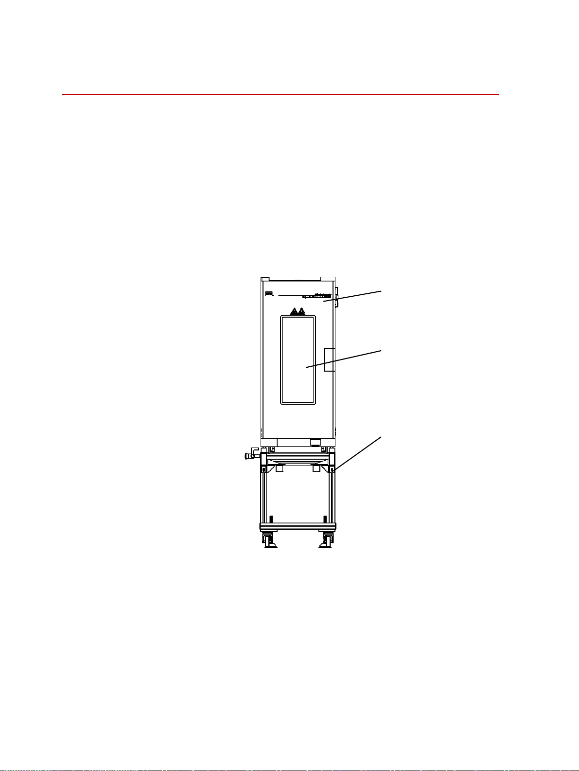
Description
Series FEC environmental chambers are used for testing the mechanical
properties of metal and nonmetal materials (for example: magnesium alloy,
plastic, and rubber.) under high and low temperature conditions. Environmental
chambers can be used with Electromechanical universal testing machine.
The MTS Series FEC Environmental Chambers let you test materials and
components within a range of temperatures, from
Cooling is accomplished with the use of liquid nitrogen introduced to the
chamber. Heating is accomplished with electrical heating elements. An electric
fan and baffle diffuse the heat for uniform temperatures. A customer-specified
temperature controller (Eurotherm) is mounted in the electrical box.
-70 ~ 350°C (- 94 ~ 662°F).
Cabinet
Observation Window
Bracket
14
Introduction
Series FEC Environmental Chamber Product Manual
Page 15
Description
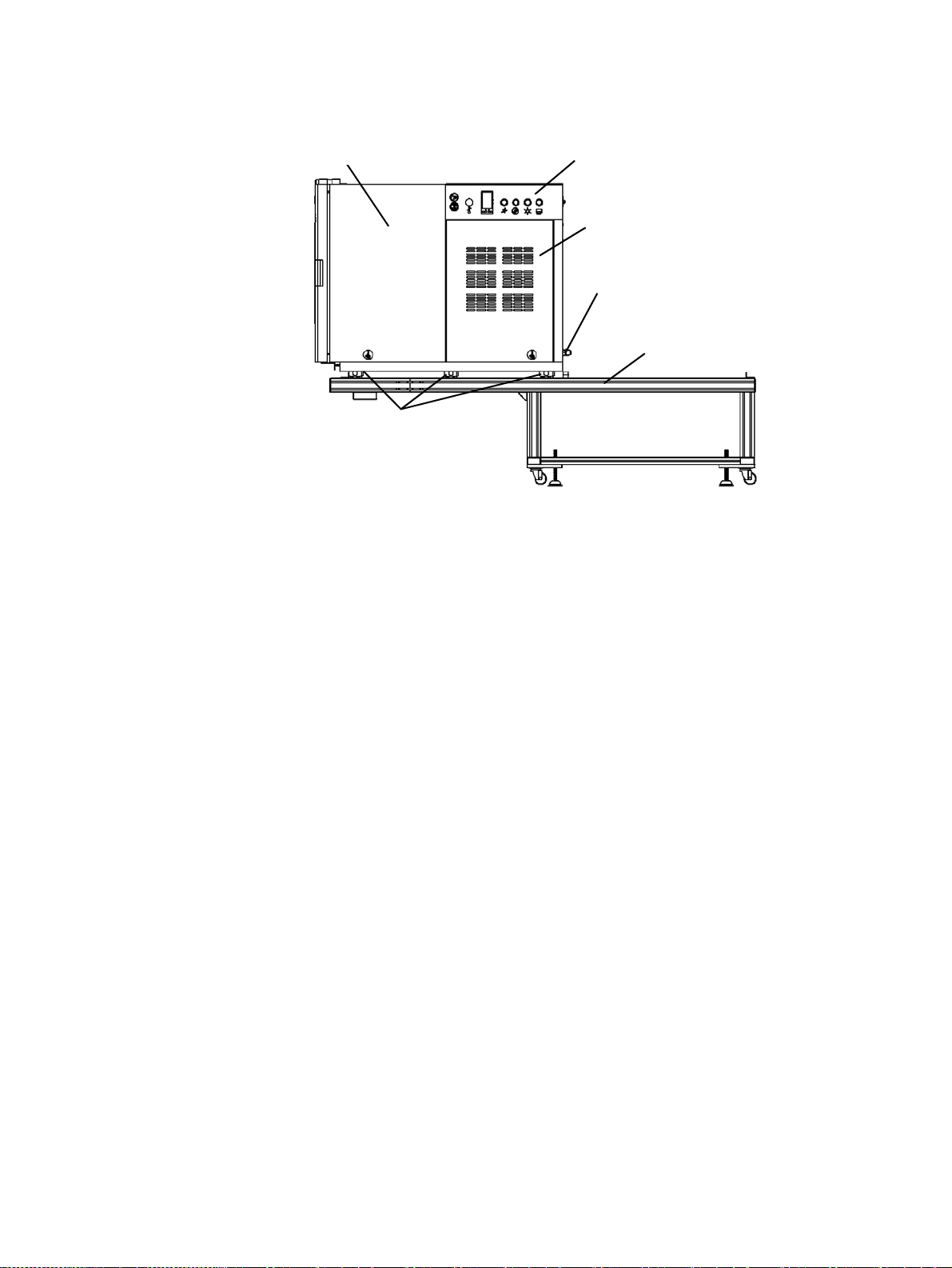
Test Space
Movable Wheels
Electric Controls
Motor, Heating and
Refrigeration pipe
Liquid Nitrogen Interface
Bracket
Cabinet The surface of the cabinet is made of painted mild-steel plate, the inner wall of
the cabinet is made of stainless steel making it temperature-resistant. The front
side of the cabinet has a door with an observation window, which you can
observe tests under illumination from the lamp that is installed on the inner wall
of the cabinet. Cooling is accomplished with the use of liquid nitrogen introduced
to the chamber. Heating is accomplished with one electrical heating element. An
electric fan and baffle diffuse the heat for uniform temperatures.
Temperature control
system
Bracket for
environmental
chamber
The temperature controller unit is integrated into the backside of the cabinet,
which allows you to perform controller adjustment easily. The temperature
control system uses a Eurotherm high-precision temperature controller, and a
solid state relay as an executing element.
The bracket can be dismantled or assembled easily.You can move the chamber
back from the test zone of testing machine via rollers on the bottom of the
cabinet.
Note FEC serial chamber can only be used on MTS frames. When you want to
use it for other purpose, you should be aware of the chamber overturn
risk due to external force.
Series FEC Environmental Chamber Product Manual Introduction
15
Page 16

Specifications
Specifications
The section provides operating condition requirements and detailed specification
of the environmental chambers.
Operating Condition Requirements
Use the environmental chambers under the following conditions:
PARAMETER SPECIFICATION
Condition For indoor application only
Ambient temperature of cabinet
Relative humidity 5-85%, noncondensing
Maximum altitude 2000 m (6562 ft)
Voltage
Frequency 50 Hz / 60 Hz
Current 15 Amps
5 ~ 40
°C (41 ~ 104°F)
Single-phase AC 200 ~ 240 V
Model and Specifications
MODEL FEC1200 FEC1300
Scope of application C43.104, C43.104E, C43.304,
C43.304E, C43.504, C43.504E,
C44.104, C44.104E, C44.304,
C44.304E
Temperature scope
External dimension (W × D × H) 360 × 1060 × 795 mm
Dimension of test space
(W × D × H)
-70 ~ 350
(14.2 × 41.7 × 31.3 in)
200 × 200 × 600 mm
(7.9 × 9.4 × 23.6 in)
°C (- 94 ~ 662°F) -70 ~ 350°C (- 94 ~ 662°F)
C45.504, C45.105
C45.504E, C45.105E
460 × 1060 × 800 mm
(18.1 × 41.7× 31.5 in)
300 × 200 × 600 mm
(11.8 × 9.4× 23.6 in)
± 10%
Temperature fluctuation
Temperature deviation
Temperature uniformity
Heatup time
Cooling time
Heatup time (room
temperature~350
Weight 105 kg 120 kg
Introduction
16
°C)
≤ ±1
°C ≤ ±1°C
≤ ±2
°C ≤ ±2°C
≤ ±2
°C ≤ ±2°C
≥ 5
°C/min ≥ 5°C/min
≥ 2
°C/min ≥ 2°C/min
≤ 60 min ≤ 60 min
Series FEC Environmental Chamber Product Manual
Page 17

Safety Information
Safety
Safety
Stay clear of moving
equipment/avoid crush
points
Know the causes of
unexpected crosshead
motions
Do not use RF
transmitters
Stay clear of mechanical linkages, connecting cables, and hoses that move
because you can get pinched, crushed, tangled, or dragged along with the
equipment. High forces generated by the system can pinch, cut, or crush anything
in the path of the equipment and cause serious injury. Stay clear of any potential
crush points. Most test systems can produce sudden, high-force motion. Never
assume that your reactions are fast enough to allow you to escape injury when a
system fails.
The high force and velocity capabilities of MTS systems can be destructive and
dangerous (especially if crosshead motion is unexpected). The most likely causes
of unexpected crosshead response are operator error and equipment failure due to
damage or abuse (such as broken, cut, or crushed cables and hoses; shorted wires;
overstressed feedback devices; and damaged components within the control
loop). Eliminate any condition that could cause unexpected crosshead motion.
Keep radio frequency (RF) transmitters away from the workstation computers,
remote terminals, and electronics consoles. Intense RF fields can cause erratic
operation of the more sensitive circuits in the system.
Hazard Placard Placement
Hazard placards contain specific safety information and are affixed directly to the
system so they are plainly visible.
Each placard describes a system-related hazard. When possible, international
symbols (icons) are used to graphically indicate the type of hazard and the
placard label indicates its severity. In some instances, the placard may contain
text that describes the hazard, the potential result if the hazard is ignored, and
general instructions about how to avoid the hazard.
The following labels are typically located on the chamber.
L
ABEL DESCRIPTION
Environmental Chamber ID
label.
Series FEC Environmental Chamber Product Manual Safety Information
17
Page 18

Hazard Placard Placement
LABEL DESCRIPTION
Lift the machine with straps.
Do not start, operate, or service
machine until you read and
understand the operator’s
manual.
Failure to do so could result in
serious injury.
There are no customerserviceable parts on the MTS
Criterion electromechanical
frames.
Burn hazard.
Hot surface.
Do not touch.
Allow to cool before servicing.
Hot surface hazard.
Do not touch.
Safety Information
18
Series FEC Environmental Chamber Product Manual
Page 19

Installation
Contents Installing Bracket of Environmental Chamber 20
Installing Environmental Chamber 22
Adjusting Environmental Chamber Position 24
Connecting Environmental Chamber Mains Power 26
Connecting Liquid Nitrogen to the Chamber 27
Series FEC Environmental Chamber Product Manual Installation
19
Page 20

Installing Bracket of Environmental Chamber
Installing Bracket of Environmental Chamber
Environmental chambers are installed onto different brackets that are composed
extruded aluminum and consist of front guide bracket and rear guide bracket.
During high and low temperature test, front and rear guide bracket are connected
and fixed onto testing machine.
Back Door of Enclosure
Front Door of
Enclosure
Crosshead
Environmental
Chamber
Front Guide
Bracket
Rear Guide
Bracket
20
Installation
Series FEC Environmental Chamber Product Manual
Page 21

Installing Bracket of Environmental Chamber
1. Install the front guide bracket to the accessory mounting locations on the
testing machine. Fix bracket onto the testing machine by adapter block, do
not tighten until alignment in next section is finished.
Fix bracket onto
the testing
machine by
adapter block.
Connect front and rear guide
with the guide connector.
2. Connect the front and rear guide bracket. Push the rear guide bracket
forward and connect it with the front guide bracket using connector.
Front Guide Bracket
Connect front and
rear guide with the
guide connector.
Series FEC Environmental Chamber Product Manual Installation
21
Page 22

Installing Environmental Chamber
Installing Environmental Chamber
Using a crane For safe, quick, and accurate installation, plan to use crane to lift Chamber , MTS
recommends using professional riggers experienced in moving heavy equipment.
Before you begin Before lifting the Chamber, ensure that:
• There are no loose accessories on the Chamber.
• There is adequate ceiling clearance to allow the Chamber to be lifted onto
bracket, including clearance for the crane.
• Your equipment operators have the appropriate licenses and have complied
with your local safety standards (for example, the appropriate training
required by OSHA in the U.S.).
Equipment The following items are required by the customer:
• A crane with a load rating that is double the Chamber’s gross weight.
• T wo lifting straps, each with a load rating that is double the Chamber’s gross
weight.
Procedure To lift the Chamber onto the bracket:
1. Remove all packaging material fromChamber and ensure that the Chamber
is not attached to the shipping skid.
2. Attach the two lifting straps to the base of Chamber and secure them to the
crane hook.
The Chamber may overturn suddenly when lifting the Chamber.
An overturned Chamber can cause injury or death to anyone in the
immediate area.
Ensure that all persons in the immediate area are standing away from the
Chamber during lifting.
3. Slowly lift the Chamber until it is lifted to the height which is higher than
that of the bracket.
4. Slowly lower the Chamber to the bracket so that it is standing on bracket
and can glide safely.
5. Remove the straps from Chamber.
WARNING
22
Installation
Series FEC Environmental Chamber Product Manual
Page 23

The chamber can now be positioned into its operating location and then installed
by an MTS service representative.
Oriented Stoppers
Installing Environmental Chamber
Environmental
Chamber
Lift environmental
chamber and put
onto matching
bracket.
Installation of Environmental Chamber
Bracket for Environmental
Chamber
Series FEC Environmental Chamber Product Manual Installation
23
Page 24

Adjusting Environmental Chamber Position
Adjusting Environmental Chamber Position
1. It is necessary to adjust the position of environmental chamber via upper
and lower pull rods on site.
Before fixing bracket and environmental chamber, slide the chamber from
front to back on the bracket, and adjust the position of the bracket from left
to right on testing machine to make the pull rods align to the center of the
rod hole of environmental chamber.
Rod Hole
Adjust position
of bracket.
Oriented Stops
Adjust position
of cabinet.
2. After the pull rods align to the center of pull rod hole of environmental
chamber, fix the bracket to the testing machine, and fix the stoppers to the
front bracket.
Fix the stoppers to locate the
front stopping point of
environmental chamber.
Align rod to center
of rod hole.
24
Installation
Series FEC Environmental Chamber Product Manual
Page 25

Adjusting Environmental Chamber Position
3. In order to prevent the danger of Chamber overturn, FEC serials chamber
use four anti-overturn blocks to connect the chamber body and the rail
bracket. Please fix the four anti-overturn blocks on the left and right side
wheel of the chamber after the chamber installation and adjustments are
done.
Door Switch
Anti-overturn Block
4. To ensure the safety of the chamber operation, a door switch is installed on
the bottom of it. When the door is open, the heating or cooling function will
be cut off and the stirring fan will stop working at the same time. After you
closed the door, the stirring fan will automatically run again, but the heating
or cooling function will not automatically go back to normal use until you
press "Enable" button again. After the chamber installation is done, please
make sure the door switch function works properly.
Series FEC Environmental Chamber Product Manual Installation
25
Page 26

Connecting Environmental Chamber Mains Power
Connecting Environmental Chamber Mains Power
Power connection For MTS series FEC chamber use the 3-wires cable that is provide for power
input, and connect to the customer electrical box and disconnect.
Note Local electrical codes supersede any information found here:
Voltage Single-phase AC 200-240
Current 15Amps
Frequency 50 Hz/60 Hz
Note Electrical connections must be made by qualified personnel and is their
responsibility for using the proper power disconnect that conforms to
local codes and regulations when connecting the machine to the building
main power.
Electrical disconnect The customer is responsible for providing an electrical power disconnect that is
easy to operate and easy to reach. It must also meet IEC 60947-1 and IEC 609473 standards. Recommended circuit breaks would be ones that are of the thermal
magnetic type with characteristics suitable for large inductive loads (D-type trip
characteristic). If fuses are used it is recommended that they are of the time delay
type with dual elements. These recommendations should be followed to avoid
nuisance tripping.
LN2 Input
Power Line
26
Installation
Series FEC Environmental Chamber Product Manual
Page 27

Connecting Liquid Nitrogen to the Chamber
Connecting Liquid Nitrogen to the Chamber
Prerequisites
• Review lab safety procedures and review any safety data furnished by the
LN2 supplier.
• Ensure that the area around the chamber is well ventilated.
WARNING
The environmental chamber is not rated for combustible liquids.
When heated, flammable and combustible liquids can explode an d cause
personal injury and equipment damage.
Do not use flammable or combustible liquids in the environmental chamber.
Always operate the chamber with the door closed.Do not override any safety
features.Do not modify the chamber without consulting MTS Systems
Corporation.
Connecting an LN2 supply tank to the chamber:
LN2 Input
Connect to liquid
nitrogen tank (Thread
size M20x1.5).
Power Line
Series FEC Environmental Chamber Product Manual Installation
27
Page 28

1. Connect a supply of clean, water-free liquid nitrogen to the coolant input
connector.
The cooling gas supply tank should be pressurized to 0.15 MPa (22 psi) for
LN2 cooling. If the supply tank pressure is greater than the recommended
pressure, install a pressure regulator between the supply tank and the
coolant solenoid.
WARNING
Use of LN2 gas in the chamber will result in a lack of oxygen in and around
the chamber.
A lack of oxygen can cause dizziness or blackouts.
Ensure that the area around the chamber is well ventilated.
2. Turn the liquid withdrawal valve on the supply tank on before beginning a
test.
Note When cooling is not being used, the liquid withdrawal valve on the supply
tank should be kept closed to prevent leakage of the coolant.
WARNING
Check the operating temperature range of each component in the
environmental chamber. All components must be able to operate at the
temperature of the test.
Damage to equipment can occur.
Do not set a testing temperature that is higher or lower than the temperature
rating of any component (grips, fixtures, and so forth.) inside the chamber.
Page 29

Operation
Contents Installing Pull Rods and Grips 30
This section describes routine operation of environmental chamber. For details
relating to software and temperature controllers, refer to the corresponding
software manual and temperature controllers manuals.
Only qualified and trained personnel should operate environmental chambers.
Operation of Temperature Controller 31
Temperature Controller Common Functions 35
Test Case 40
WARNING
The environmental chamber is not rated for combustible liquids.
When heated, flammable and combustible liquids can explode an d cause
personal injury and equipment damage.
Do not use flammable or combustible liquids in the environmental chamber.
Always operate the chamber with the door closed.Do not override any safety
features.Do not modify the chamber without consulting MTS Systems
Corporation.
Series FEC Environmental Chamber Product Manual Operation
29
Page 30

Installing Pull Rods and Grips
Installing Pull Rods and Grips
1. Remove the U-plugs in the top and bottom walls of the chamber.
2. Mount upper pull rod to the crosshead, and lower pull rod to the base of
testing machine.
3. Mount upper grip to upper rod, and lower grip to lower pull rod.
4. Push the environmental chamber into position so that the pull rods are
centered with respect to the access ports of the chamber.
5. Install the specimen and all of its instrumentation.
6. Reinstall the U-plugs in the chamber removed in step 1.
7. Close the front door, and you are ready to run the environmental chamber.
Upper U-plug
Lower U-plug
Remove the U-plugs,
push environmental
chamber into position.
Align rod to center
of rod hole after
assembled cabinet
completely.
30
Operation
Reinstall U-plugs
Series FEC Environmental Chamber Product Manual
Page 31

Operation of Temperature Controller
The temperature controller is located at the rear of the cabinet, which allows you
to connect it with the computer and set parameters via the software easily.
Inspect if cables are connected correctly before turning on power.
Set the test temperature in the allowable temperature range without exceeding the
minimum or maximum temperature.
Operation of Temperature Controller
FUNCTION DESCRIPTION
Alarm light-when the temperature exceeds the
maximum temperature of chamber, the light lights.
Starts the heating or cooling.
Disables (stops) the heating or cooling.
Control switch of the illuminating lamp in the
cabinet.
A switch used for removing frost on the glass
observation window during a low-temperature test.
Series FEC Environmental Chamber Product Manual Operation
31
Page 32

Operation of Temperature Controller
POWER: Power switch of environmental chamber.
COMM.: Communication interface. Environmental chamber connects with the
computer via this interface. The required temperature and parameters
can be set for a test via this interface.Temperature information can be
read through software in real time. The interface use 9 pins connectors
and three of them are used. Pin assignments are as follows:
PIN SIGNAL
1 No Contact
2 COMM A+
3 COMM B-
4 GND
5 No Contact
6 No Contact
7 No Contact
8 No Contact
9 No Contact
32
Operation
Series FEC Environmental Chamber Product Manual
Page 33

Operation of Temperature Controller
E-STOP: The J1 connector should be connected to either J14 of the Frame
Controller or J2 of another Accessory with an Emergency Stop board.
The J2 connector will either have a jumper plug or be connected to J1
of another Accessory with an Emergency Stop board.
J1 E-STOP pin assignments are as follows:
P
IN SIGNAL
1 ESTOP3B-
2 No Contact
3 No Contact
4 ESTOP_OUT_MONITOR+
5 ESTOPB_IN+
6 ESTOP3A-
7 ESTOPB_IN-
8 ESTOPA_IN+
9 ESTOP3B+
10 ESTOP_OUT_MONITOR-
11 No Contact
12 No Contact
13 ESTOPA_IN-
14 ESTOP3A+
15 No Contact
Series FEC Environmental Chamber Product Manual Operation
33
Page 34

Operation of Temperature Controller
J2 E-STOP pin assignments are as follows:
IN SIGNAL
P
1 ESTOPB_OUT-
2 No Contact
3 ESTOP_OUT_MONITOR-
4 ESTOP_OUT_MONITOR+
5 ESTOP3B+
6 ESTOPA_OUT-
7 ESTOP3B-
8 ESTOP3A+
9 ESTOPB_OUT+
10 No Contact
11 No Contact
12 No Contact
13 ESTOP3A-
14 ESTOPA_OUT+
15 No Contact
34
Operation
Series FEC Environmental Chamber Product Manual
Page 35

Temperature Controller Common Functions
Temperature Controller Common Functions
The Environmental Chamber uses a Eurotherm2408 as temperature controller.
The following describes the operation of manual settings and some of its
methods and procedures.
For details relating to setting test temperature and various control parameters,
refer to"Eurotherm Manual". For setting test temperature and control parameters
via software, refer to the attached software application manual.
1. Setting test temperature:
Press or key directly to adjust the temperature
.
Temperature Indicating
Val ue
Temperature Setting
Val ue
Arrow keys are used for
setting temperature and
parameters.
2. Setting PID control parameters:
PID control parameters are the key parameters to control the temperature.
Generally, different temperatures require different PID parameters. When
setting the temperature, refer to the corresponding information to enter the
correct parameters. Based on parameters tables given in the Eurotherm
manual to set three parameters, Pb (P pa rameter ), ti ( I para meter), an d td (D
parameter). The following flow chart briefly illustrates the methods to set
the three parameters (PID).
Series FEC Environmental Chamber Product Manual Operation
35
Page 36

Temperature Controller Common Functions
20.0
350.0
Goto
FuLL
$IWHU )X// IODVKLQJ
SUHVV
20.0
350.0
3UHVV
WLPHV WLPHV
3UHVV
WLPHV
WR H[LW
FRQWLQXRXV
SUHVV
ACCS
LISt
codE
PASS
LISt
3UHVV
ZDLW
VHFRQGV
SUHVV
WR ILQG 3
codE
0
3UHVV WLPHV
codE
1
PbPId
30
SUHVV
WR ILQG ,
60
SUHVV
WR ILQG '
tI
360
20.0 td
350.0
3. Set heating and cooling parameters:
The temperature controller uses dual channels to control the temperature.
Channel 1 is the heating channel; channel 2 is the cooling channel. Relevant
parameters have been set at the factory; do not change the parameters. If
there are some abnormal phenomena, enter the following parameters to help
it return to normal state.
conF -insT -Act = rEu
conF -1A - Func = HEAt
conF -2A - Func = CooL
The following flow chart illustrates the method to set these parameters.
SUHVV
WR H[LW
Setting PID Parameters
36
Operation
Series FEC Environmental Chamber Product Manual
Page 37

Temperature Controller Common Functions
20.0
350.0
conF
$IWHU 3$66
SUHVV
20.0
350.0
SUHVV
WR $&&6
SUHVV
2
VHW FRQ)
WR H[LW
SUHVV SUHVV
WR ,QVW SDJH
ACCS
LISt
Goto
conF
InSt
ConF
SUHVV
VHW FRG(
SUVVV
LQWR FRQ)
WR ILQG $FW
codE
1
SUHVV
LQWR
*RWR SDJH
Goto
FuLL
Act
rEu
SUHVV
LQWR $ SDJH
2A
ConF
᤹
)XQF
Func
CooL
Set Heating and Cooling Parameters
When manually setting the environmental chamber to the heating state, the
following two parameters need to be set:
FuLL - oP - Op.Lo = 0.0
FuLL - oP - Op.HI = 80.0
SUHVV
LQWR $ SDJH
WR ILQG
SUHVV
LQWR (GLW
SDJH
Func
HEAt
EdIt
YES
SUHVV
WR ILQG )XQF
5HVWDUW
FRQWUROOHU
1A
ConF
20.0
350.0
Series FEC Environmental Chamber Product Manual Operation
37
Page 38

Temperature Controller Common Functions
Below is the chart flow.
20.0
350.0
Goto
SUHVV
WLPHV
SUHVV
FuLL
$IWHU )X// IODVKLQJ
SUHVV
20.0
350.0
WR H[LW
SUHVV
WR R3
ACCS
LISt
codE
PASS
oP oP. Lo
LISt
SUHVV
ZDLW
VHFRQGV
SUHVV
WR R3/R
codE
0
SUHVV
codE
1
0.0
SUHVV
WR R3+L
20.0
350.0
Set Heating Parameters
When manually setting the temperature chamber to the cooling state, the
following two parameters need to be set:
FuLL - oP - Op.Lo = -80.0
FuLL - oP - Op.HI = 0.0
Below is the chart flow.
SUHVV
WR ([LW
oP. HI
80.0
38
Operation
Series FEC Environmental Chamber Product Manual
Page 39

Temperature Controller Common Functions
20.0
350.0
Goto
SUHVV
WLPHV
SUHVV
FuLL
$IWHU )X// IODVKLQJ
WR H[LWSUHVV
20.0
350.0
SUHVV
WR R3
ACCS
LISt
codE
PASS
oP oP. Lo
LISt
SUHVV
ZDLW
VHFRQGV
SUHVV
WR R3/R
codE
0
SUHVV
codE
1
-80.0
SUHVV
WR R3+L
20.0
350.0
Set Cooling Parameters
SUHVV
WR ([LW
oP. HI
0.0
Series FEC Environmental Chamber Product Manual Operation
39
Page 40

Test Case
Do not expose skin to the inner side of the cabinet or the sample while installing
or uninstalling the sample because the temperature of the sample or inside of the
cabinet may be very hot or cold. Install/uninstall sample using proper tools, and
perform the operation strictly according to safe operating regulations of your
laboratory.
High temperature test
procedure
To perform a high temperature test:
1. Remove the U-plugs in the top and bottom walls of the chamber.
2. Mount upper pull rod to the crosshead, and lower pull rod to the base of
testing machine.
3. Mount upper grip to upper rod, and lower grip to lower pull rod.
4. Push the environmental chamber into the test space.
5. Install the specimen and all of its instrumentation.
6. Reinstall the U-plugs into the top and bottom walls of the chamber.
7. Close the front door.
8. Press the power switch to On positioin.
9. Confirm that the temperature controller apparatus is set to the heating state.
And set the test temperature and operating parameters corresponding to the
temperature point.
Set the temperature.
10. Press the“ENABLE” button to start the chamber heating process.
11. After achieving the setting temperature and hold appointed time at the
temperature, you can start the high-temperature test via test software.
12. Press the“DISABLE” button after you have finished testing the sample.
13. Open the chamber door. Allow the specimen to return to room temperature,
if possible.
Press this button to enable the chamber
Page 41

14. Remove the specimen from the grips following the instructions in the
appropriate grip manual.
Cooling test procedure To perform a cooling test:
1. Connect liquid nitrogen tank to the environmental chambers, and ensure no
leakage.
2. Remove the U-plugs in the top and bottom walls of the chamber.
3. Mount upper pull rod to the crosshead, and lower pull rod to the base of
testing machine.
4. Mount upper grip to upper rod, and lower grip to lower pull rod.
5. Push the environmental chamber into the test space.
6. Install the specimen and all of its instumentation.
7. Replace the U-plugs into the top and bottom walls of the chamber.
8. Close the front door.
9. Press the power switch to On positioin.
Test Case
10. Confirm that the temperature controller apparatus is set to cooling state.
And set the test temperature and operating parameters corresponding to the
temperature point.
11. Press the“ENABLE” button to start the chamber cooling process.
12. After achieving the setting temperature and hold appointed time at the
temperature, you can start the low-temperature test via test software.
13. Press the“DISABLE” button after you have finished testing the sample.
14. Open the chamber door. Allow the specimen to return to room temperature,
if possible.
15. Remove the specimen from the grips following the instructions in the
appropriate grip manual.
Series FEC Environmental Chamber Product Manual Operation
41
Page 42

Test Case
42
Operation
Series FEC Environmental Chamber Product Manual
Page 43

Routine Maintenance
Routine Maintenance Overview Checklist
Recommended Service
Routine Maintenance
CALENDAR TIME USING 8 HOURS RUNNING TIME
R
ATE PER DAY
RUNNING TIME-HOURS 8 40 2000
Clean the chamber inside/chamber surface area
Check the door limit and E-stop X
Check the cable connection X
Check all the buttons function X
System Inspection
Check the cable connection MTS
System Checks
Check E-stop MTS
Check door switch MTS
Check rail bracket level MTS
Check over-temperature alarm instrument
function
Lubrication
Stirring fan bearing MTS
DAILY WEEKLY ANNUALLY
*
X
MTS
* Denotes services performed by equipment operators. Most of these procedures involve visual checks
that should not interfere with testing system operation. These checks are also completed by trained
field service engineers on each Routine Maintenance visit.
Series FEC Environmental Chamber Product Manual Routine Maintenance
43
Page 44

• Do not open the chamber immediately after a test to prevent damage or
personal injury caused by high or low temperature.
• To extend the service life of an environmental chamber, eliminate water
vapor in the cabinet or other residue left in the chamber after test.
• Do not use corrosive organic solvents when cleaning chamber.
• During test or after test, do not use any kind of shelter to cover the chamber
so as to avoid the case that the heat or water vapor can not be diffused and
damage the chamber.
Troubleshooting
Troubleshooting
YMPTOMS REASON SOLUTION
S
Routine Maintenance
Set Value window flashes and
displays “S.br” .
T emperature increase speed is
slower than original speed
Temperature rises out of
control
Temperature fails to mains at
setting temperature
Measure signal input
exceeds range.
Parameter setting may be
incorrect.
parameter setting is
incorrect.
Control parameter is
imperfect or lost.
1. Inspect if specification setting of
sensor is correct.
2. Inspect if signal input is open circuit.
Inspect if setting of temperature control
parameter is correct.
Inspect if setting of temperature control
parameter is correct.
Start self-adjustment to find out proper
control parameter.
Series FEC Environmental Chamber Product Manual Routine Maintenance
44
Page 45

Declaration of Conformity
Series FEC Environmental Chamber Product Manual Declaration of Conformity
45
Page 46

Declaration of Conformity
46
Series FEC Environmental Chamber Product Manual
Page 47

Page 48

m
MTS Systems Corporation
http://www.mts.com/en/Global/index.asp
ISO 9001 Certified QMS
 Loading...