

Page 1

Series 647 Hydraulic Wedge Grips Reference
Manual
Axial Grips Axial-Torsional Grips All-Temperature Grips
100-027-131 N be certain.
Page 2

© 2013 MTS Systems Corporation. All rights reserved.
Original Instructions (English): 100-027-131 N
Trademark Information
MTS, be certain., Bionix, ElastomerExpress, FlatTrac, FlexTest, Just In Case, LevelPlus, MTS Criterion, MTS
EM Extend, MTS Insight, MTS Landmark, RPC, ServoSensor, SWIFT, Temposonics, TestWare, TestWorks are
registered trademarks of MTS Systems Corporation within the United States. Acumen, Advantage, Aero ST,
Aero-90, AeroPro, Criterion, CRPC, Echo, Flat-Trac, Landmark, MAST, MicroProfiler, MPT, MTS Acumen, MTS
Echo, MTS Fundamentals, MTS TestSuite, ReNew, SilentFlo, TempoGuard, TestLine, and Tytron are trademarks
of MTS Systems Corporation within the United States. These trademarks may be registered in other countries.
All other trademarks are property of their respective owners.
Proprietary Software
Software use and license is governed by the MTS End User License Agreement which defines all rights retained
by MTS and granted to the End User. All Software is proprietary, confidential, and owned by MTS Systems
Corporation and cannot be copied, reproduced, disassembled, decompiled, reverse engineered, or distributed
without express written consent of MTS.
Software Verification and Validation
MTS software is developed using established quality practices in accordance with the requirements detailed in
the ISO 9001 standards. Because MTS-authored software is delivered in binary format, it is not user accessible.
This software will not change over time. Many releases are written to be backwards compatible, creating another
form of verification. The status and validity of the MTS operating software is also checked during system verification
and routine calibration of MTS hardware. These controlled calibration processes compare the final test results
after statistical analysis against the predicted response of the calibration standards. With these established
methods, MTS assures its customers that MTS products meet exacting quality standards when initially installed
and will continue to perform as intended over time.
Manual Part Number—Publication Date—Release
100-027-131 M—April 2011
100-027-131 L—April 2010
100-027-131 K—April 2009
100-027-131 J—March 2008
100-027-131 H—Mat 2007
100-027-131 G—November 2006
100-027-131 F—July 2005
100-027-131 E—February 2003
100-027-131 D—October 2001
100-027-131 C—June 2011
100-027-131 B—December 2011
100-027-131 A—February 2000
Page 3

Contents
Technical Support 7
Preface 11
Introduction 13
How to Get Technical Support.................................................................................................................7
Before You Contact MTS.........................................................................................................................7
If You Contact MTS by Phone.................................................................................................................9
Problem Submittal Form in MTS Manuals............................................................................................10
Before You Begin...................................................................................................................................11
Documentation Conventions..................................................................................................................11
Overview Reference...............................................................................................................................14
Series 647 Hydraulic Wedge Grips Component Identication..............................................................16
Series 647 Hydraulic Wedge Grips Functional Description...................................................................19
About Gripping Specimens....................................................................................................................20
About Wedges........................................................................................................................................20
About Spiral Washers.............................................................................................................................21
About Couplings....................................................................................................................................21
About All Temperature Grips.................................................................................................................21
About Environmental Chambers............................................................................................................22
Hydraulic Fluid Recommendations........................................................................................................23
Cooling Water Specications.................................................................................................................23
Series 647 Wedge Grip Temperature Ranges.........................................................................................23
Series 647 Hydraulic Wedge Grip Force and Torque Capacities...........................................................24
Safety 29
General Safety Practices: Grips and Fixtures.........................................................................................30
Read all manuals........................................................................................................................31
Avoid Pinch and Crush Points....................................................................................................31
Locate and read hazard placards/labels......................................................................................31
Know facility safe procedures....................................................................................................32
Know controls............................................................................................................................32
Know Specimen Properties........................................................................................................32
Have rst aid available...............................................................................................................32
Be aware of component movement with hydraulics off.............................................................32
Keep bystanders safely away.....................................................................................................32
Wear proper clothing..................................................................................................................32
Remove ammable uids..........................................................................................................32
Check bolt ratings and torques...................................................................................................33
Lift Equipment Safely................................................................................................................33
Series 647 Hydraulic Wedge Grips Reference Manual 3
Page 4

Practice good housekeeping.......................................................................................................33
Do not exceed the Maximum Supply Pressure..........................................................................33
Do not disable safety devices.....................................................................................................33
Provide adequate lighting...........................................................................................................33
Provide means to access out-of-reach components....................................................................34
Wear appropriate personal protection.........................................................................................34
Handle chemicals safely ............................................................................................................34
Know system interlocks.............................................................................................................34
Know system limits....................................................................................................................34
Do not disturb sensors ...............................................................................................................34
Ensure secure cables...................................................................................................................34
Stay alert ....................................................................................................................................35
Contain small leaks ...................................................................................................................35
Stay clear of moving equipment/avoid crush points .................................................................35
Know the causes of unexpected actuator motions .....................................................................35
General Precautions for Environmental Components............................................................................35
Hazard Placard Placement......................................................................................................................36
Installation 37
Series 647 Hydraulic Grip Lift Points....................................................................................................38
Install Axial Grips..................................................................................................................................39
About the Installation of Axial Grips.........................................................................................39
Install Axial Grip........................................................................................................................42
Install Axial-Torsional Grips..................................................................................................................44
About the Installation of Axial-Torsional Grips.........................................................................44
Install Axial-Torsional Grip.......................................................................................................46
Install 647.250 Grips..............................................................................................................................50
Install the Grips in an Environmental Chamber.....................................................................................50
About Installation of the Grips in an Environmental Chamber .................................................50
Install Environmental Chambers with U-Plugs..........................................................................51
Install Environmental Chambers Without U-Plugs....................................................................55
Install Extension Rods............................................................................................................................66
About Extension Rod Installation..............................................................................................66
Install Extension Rods................................................................................................................67
Align the Wedge Openings.....................................................................................................................71
Preload the Spiral Washers.....................................................................................................................72
Grip Water Cooling Congurations.......................................................................................................74
Grip Water Cooling Assembly Conguration for Electromechanical Frames...........................74
Operation 77
Basic Operation......................................................................................................................................78
About Grip Controls...............................................................................................................................78
Determine Gripping Pressure.................................................................................................................79
4 Series 647 Hydraulic Wedge Grips Reference Manual
Page 5

About Grip Pressure Determination...........................................................................................79
Determine Gripping Pressure -Axial for Round Specimens (and Axial/Torsional for Flat Specimens).81
Determine Gripping Pressure - Axial-Torsional for Round Specimens Only............................82
Change/Install Wedges...........................................................................................................................83
Change Model 647.02 - 647.100 Wedges..................................................................................83
Change Standard Wedges...........................................................................................................83
Change Wide Wedges.................................................................................................................84
Wedges and Inserts for Rebar and Wire Rope............................................................................85
Install Model 647.250 Wedges and Liners.................................................................................86
Install Model 647.250 Wedges.......................................................................................86
Install Model 647.250 Wedge Liners.............................................................................87
Install/Remove Test Specimen...................................................................................................88
Install a Specimen..........................................................................................................88
Remove a Specimen.......................................................................................................90
Maintenance 93
Hydraulic Hoses and Fittings.................................................................................................................94
Wedges...................................................................................................................................................94
Water Cooling Components...................................................................................................................94
Daily Inspections....................................................................................................................................94
Series 647 Hydraulic Wedge Grips Reference Manual 5
Page 6

Page 7

Technical Support
How to Get Technical Support
Start with your manuals
The manuals supplied by MTS provide most of the information you need to use and maintain your equipment.
If your equipment includes software, look for online help and README files that contain additional product
information.
Technical support methods
MTS provides a full range of support services after your system is installed. If you have any questions about
a system or product, contact Technical Support in one of the following ways.
Web site
Outside the U.S.
For technical support outside the United States, contact your local sales and service office. For a list of
worldwide sales and service locations and contact information, use the Global MTS link at the MTS web site:
www.mts.com > Global Presence > Choose a Region
www.mts.com > Contact Us (upper-right corner) > In the Subject field, choose
To escalate a problem; Problem Submittal Form
Worldwide: tech.support@mts.comE-mail
Europe: techsupport.europe@mts.com
Worldwide: 1 800 328 2255 - toll free in U.S.; +1 952 937 4000 - outside U.S.Telephone
Europe: +800 81002 222, International toll free in Europe
Before You Contact MTS
MTS can help you more efficiently if you have the following information available when you contact us for
support.
Know your site number and system number
The site number contains your company number and identifies your equipment type (such as material testing
or simulation). The number is typically written on a label on your equipment before the system leaves MTS.
If you do not know your MTS site number, contact your sales engineer.
Example site number: 571167
Series 647 Hydraulic Wedge Grips Reference Manual 7
Page 8

When you have more than one MTS system, the system job number identifies your system. You can find
your job number in your order paperwork.
Example system number: US1.42460
Know information from prior technical assistance
If you have contacted MTS about this problem before, we can recall your file based on the:
• MTS notification number
• Name of the person who helped you
Identify the problem
Describe the problem and know the answers to the following questions:
• How long and how often has the problem occurred?
• Can you reproduce the problem?
• Were any hardware or software changes made to the system before the problem started?
• What are the equipment model numbers?
• What is the controller model (if applicable)?
• What is the system configuration?
Know relevant computer information
For a computer problem, have the following information available:
• Manufacturer’s name and model number
• Operating software type and service patch information
• Amount of system memory
• Amount of free space on the hard drive where the application resides
• Current status of hard-drive fragmentation
• Connection status to a corporate network
Know relevant software information
For software application problems, have the following information available:
• The software application’s name, version number, build number, and (if available) software patch number.
This information can typically be found in the About selection in the Help menu.
• The names of other applications on your computer, such as:
• Anti-virus software
• Screen savers
• Keyboard enhancers
• Print spoolers
• Messaging applications
8 Series 647 Hydraulic Wedge Grips Reference Manual
Page 9

If You Contact MTS by Phone
A Call Center agent registers your call before connecting you with a technical support specialist. The agent
asks you for your:
• Site number
• Name
• Company name
• Company address
• Phone number where you can be reached
If your issue has a notification number, please provide that number. A new issue will be assigned a unique
notification number.
Identify system type
To enable the Call Center agent to connect you with the most qualified technical support specialist available,
identify your system as one of the following types:
• Electrodynamic material test system
• Electromechanical material test system
• Hydromechanical material test system
• Vehicle test system
• Vehicle component test system
• Aero test system
Be prepared to troubleshoot
Prepare to perform troubleshooting while on the phone:
• Call from a telephone close to the system so that you can implement suggestions made over the phone.
• Have the original operating and application software media available.
• If you are not familiar with all aspects of the equipment operation, have an experienced user nearby to
assist you.
Write down relevant information
In case Technical Support must call you:
• Verify the notification number.
• Record the name of the person who helped you.
• Write down any specific instructions.
Series 647 Hydraulic Wedge Grips Reference Manual 9
Page 10

After you call
MTS logs and tracks all calls to ensure that you receive assistance for your problem or request. If you have
questions about the status of your problem or have additional information to report, please contact Technical
Support again and provide your original notification number.
Problem Submittal Form in MTS Manuals
Use the Problem Submittal Form to communicate problems with your software, hardware, manuals, or service
that are not resolved to your satisfaction through the technical support process. The form includes check
boxes that allow you to indicate the urgency of your problem and your expectation of an acceptable response
time. We guarantee a timely response—your feedback is important to us.
You can access the Problem Submittal Form at www.mts.com > Contact Us (upper-right corner) > In the
Subject field, choose To escalate a problem; Problem Submittal Form
10 Series 647 Hydraulic Wedge Grips Reference Manual
Page 11

Preface
Before You Begin
Safety first!
Before you use your MTS product or system, read and understand the safety information provided with your
system. Improper installation, operation, or maintenance can result in hazardous conditions that can cause
severe personal injury or death, or damage to your equipment and specimen. Again, read and understand
the safety information provided with your system before you continue. It is very important that you remain
aware of hazards that apply to your system.
Other MTS manuals
In addition to this manual, you may receive additional manuals in paper or electronic form.
You may also receive an MTS System Documentation CD. It contains an electronic copy of the manuals that
pertain to your test system.
Controller and application software manuals are typically included on the software CD distribution disc(s).
Documentation Conventions
The following paragraphs describe some of the conventions that are used in your MTS manuals.
Hazard conventions
Hazard notices may be embedded in this manual. These notices contain safety information that is specific to
the activity to be performed. Hazard notices immediately precede the step or procedure that may lead to an
associated hazard. Read all hazard notices carefully and follow all directions and recommendations. Three
different levels of hazard notices may appear in your manuals. Following are examples of all three levels. (for
general safety information, see the safety information provided with your system.)
DANGER:
Danger notices indicate the presence of a hazard with a high level of risk which, if
ignored, will result in death, severe personal injury, or substantial property damage.
WARNING:
Warning notices indicate the presence of a hazard with a medium level of risk which,
if ignored, can result in death, severe personal injury, or substantial property damage.
CAUTION:
Series 647 Hydraulic Wedge Grips Reference Manual 11
Page 12

Caution notices indicate the presence of a hazard with a low level of risk which, if
ignored, could cause moderate or minor personal injury or equipment damage, or
could endanger test integrity.
Other special text conventions
Important:
Important notices provide information about your system that is essential to its proper
function. While not safety-related, if the important information is ignored, test results may
not be reliable, or your system may not operate properly.
Note:
Notes provide additional information about operating your system or highlight easily
overlooked information.
Recommended:
Recommended notes provide a suggested way to accomplish a task based on what MTS
has found to be most effective.
Tip:
Tips provide helpful information or a hint about how to most efficiently accomplish a task.
Access:
Access provides the route you should follow to a referenced item in the software.
Example:
Examples show specific scenarios relating to your product and appear with a shaded
background.
Special terms
The first occurrence of special terms is shown in italics.
Illustrations
Illustrations appear in this manual to clarify text. They are examples only and do not necessarily represent
your actual system configuration, test application, or software.
Electronic manual conventions
This manual is available as an electronic document in the Portable Document File (PDF) format. It can be
viewed on any computer that has Adobe Acrobat Reader installed.
Hypertext links
The electronic document has many hypertext links displayed in a blue font. All blue words in the body text,
along with all contents entries and index page numbers, are hypertext links. When you click a hypertext link,
the application jumps to the corresponding topic.
12 Series 647 Hydraulic Wedge Grips Reference Manual
Page 13

Introduction
Topics:
•
Overview Reference..............................................................................................................................14
•
Series 647 Hydraulic Wedge Grips Component Identification...............................................................16
•
Series 647 Hydraulic Wedge Grips Functional Description...................................................................19
•
About Gripping Specimens....................................................................................................................20
•
About Wedges.......................................................................................................................................20
•
About Spiral Washers............................................................................................................................21
•
About Couplings.....................................................................................................................................21
•
About All Temperature Grips..................................................................................................................21
•
About Environmental Chambers............................................................................................................22
•
Hydraulic Fluid Recommendations........................................................................................................23
•
Cooling Water Specifications.................................................................................................................23
•
Series 647 Wedge Grip Temperature Ranges.......................................................................................23
•
Series 647 Hydraulic Wedge Grip Force and Torque Capacities..........................................................24
Series 647 Hydraulic Wedge Grips Reference Manual 13
Page 14
Introduction
Overview Reference
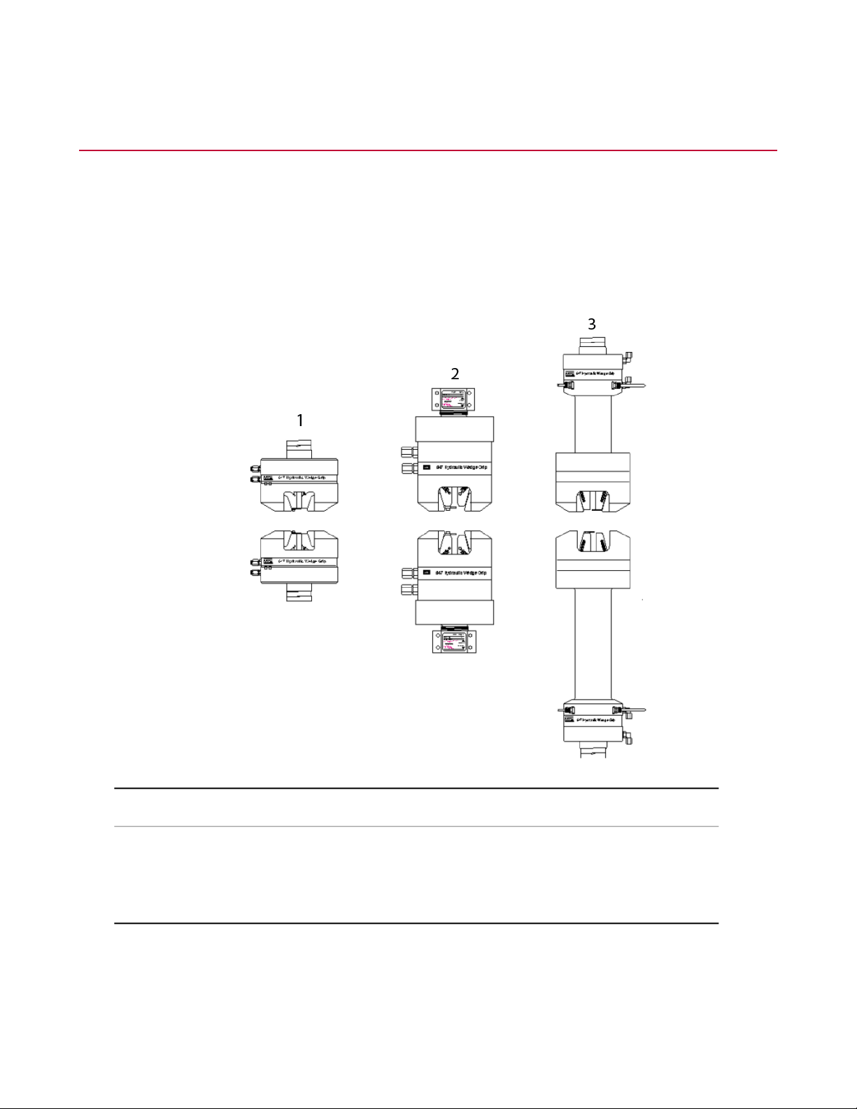
The MTS Series 647 Hydraulic Wedge Grips grasp and hold a specimen in place during testing, and provide
a constant, hydraulically actuated gripping force regardless of the applied test loads. The grips are specifically
designed for static or fatigue testing applications in MTS testing systems. A variety of wedges allow the grips
to be used to test a variety of materials. Optional equipment includes a cooling/warming kit and an external
hydraulic grip supply.
The size and shape of the Series 647 Hydraulic Wedge Grips vary among the models.
Grip TypeItem
Axial1
Axial-Torsional2
All Temperature3
What you need to know
MTS Systems Corporation assumes that you know how to use your controller. See the appropriate manual
for information about performing any controllerrelated step in this manual’s procedures. You are expected to
know how to perform the following procedures:
14 Series 647 Hydraulic Wedge Grips Reference Manual
Page 15

Introduction
• Turn hydraulic pressure on and off.
• Select a control mode.
• Manually adjust the actuator position.
• Monitor a sensor signal.
Related products
See the following product information manuals for information about the related products.
• The hydraulic controls for the Series 647 Hydraulic Grips can be located on the front panel of the load unit
or on an external unit (controls and a hydraulic power unit for the grips).
• If hydraulic grip controls are located on the load unit, see your load unit product information manual.
• If hydraulic grip controls are added to your load unit, see the 685.53 Hydraulic Grip Kit Product
Information manual (MTS part number 015-029-701).
• If you have a dedicated hydraulic supply for the grips, see the Series 685 Hydraulic Grip Supply Product
Information manual (MTS part number 015-205-001).
• If you are using an environmental chamber, see the Series 651 Environmental Chambers Product
Information manual (MTS part number 015-205-001).
Series 647 Hydraulic Wedge Grips Reference Manual 15
Page 16
Introduction
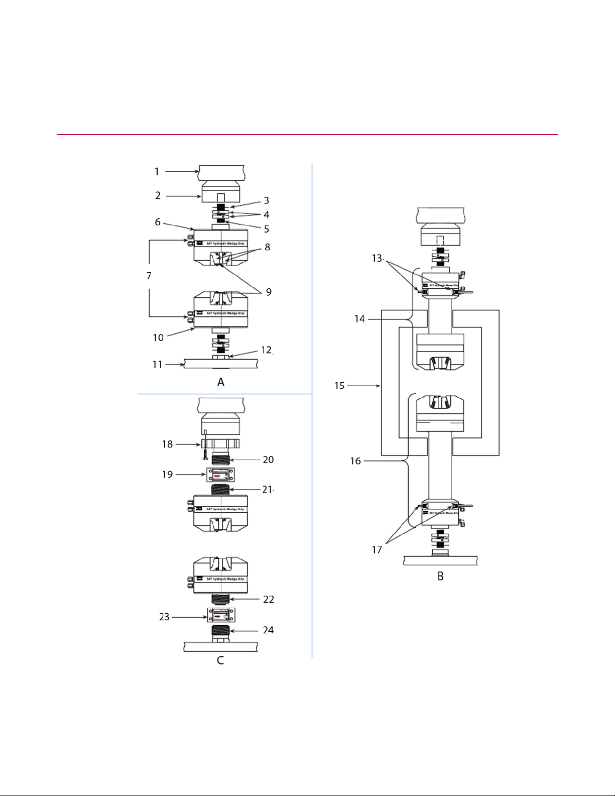
Series 647 Hydraulic Wedge Grips Component Identification
Series 647 Hydraulic Grip Components
16 Series 647 Hydraulic Wedge Grips Reference Manual
Page 17

Introduction
DescriptionItemDescriptionItem
All Temperature GripsBAxial GripsA
Water Cooling Lines13Load Unit Crosshead1
Upper Grip Assembly14Force Transducer2
Environmental Chamber15Shim3
Lower Grip Assy16Spiral Washer Set4
Water Cooling Lines17Connector Stud5
Axial/Torsional GripsCUpper Grip6
Adapter Plate18Hydraulic Pressure and return Lines7
8
liners)
Load unit
• Crosshead and Base
Plate
Upper Coupling19Wedges (647.250 includes wedge
Left Hand Thread20Specimen Guide9
Right Hand Thread21Lower Grip10
Left Hand Thread22Load Unit Base11
Lower Coupling23Actuator Rod12
Right Hand Thread24
DescriptionItem
Provides the structure to mount the grips and other components in
the force train. It is also the reaction mass for the force train. The grips
are mounted to the force transducer and actuator rod in the load unit.
• Some load units have the actuator mounted in the base plate and
the force transducer mounted to the crosshead.
• Some load units have the force transducer mounted in the base
plate and the actuator mounted to the crosshead.
Force Transducer
Upper and lower grips
Hydraulic pressure and
return lines
Measures the axial forces applied to the specimen. An axial-torsional
version also measures the rotational forces applied to the specimen.
Clamps a specimen in place. The grips house the wedges and the
hydraulic components that operate the grips.
The grip assemblies of the all-temperature grips have the components
separated so those components most affected by extreme
temperatures are located outside the extreme environment.
Ports the hydraulic fluid to and from the grips. The hydraulic fluid
comes from a system hydraulic power unit (HPU) or a dedicated
Series 647 Hydraulic Wedge Grips Reference Manual 17
Page 18

Introduction
DescriptionItem
hydraulic grip supply. Each grip has two hydraulic lines connected to
it; a hydraulic pressure port and a hydraulic return port.
Wedges
Specimen guide
Actuator rod
Water cooling lines
Environmental chamber
Contacts and holds the specimen in place. A variety of wedges are
available, for flat specimens, round specimens, hard specimens, and
soft specimens. Wedges are available as matched sets of four.
Each model has wedges that are designed for its use. The 647.250
grips have permanent wedges and use wedge liners to accommodate
various specimen shapes.
Helps align the specimen when it is installed. The specimen guide
can only be used with flat specimens.
Applies axial or axial and torsional forces to specimens. The actuator
is a hydraulically powered device that provides linear displacement
of (or forces into) a specimen. For axial-torsional systems, the actuator
applies both axial and torsional forces to the specimen.
The end of the actuator rod is threaded so that a grip can be mounted
to it. The actuator rod can be located in the base or the crosshead of
the load unit.
Provides the source of water for heating or cooling. The water is
circulated through the grips to keep them warm or cool when operating
in a cold or hot environmental chamber.
Allows a specimen to be tested at different temperatures (hot or cold).
Environmental chambers are insulated boxes that surround the
specimen and grips.
Axial attachment kit
• Shims
• Spiral washers
• Connector stud
Axial-torsional attachment
kit
Includes the required components to install the grips. The attachment
kit contains shim washers, spiral washers, and connector studs. Each
grip model/load unit model combination has a unique attachment kit.
Allows the upper and lower grips to be aligned. When the grips are
installed, the upper and lower grips might not be aligned. Shims can
be added so that the grips are aligned when they are tightened on
the connector stud. The shims are available in thicknesses that
correspond with 1/8 to 1/2 turns.
Ensures preloading without inducing offsets in the force train. They
provide a backlash-free union of threaded components. They preload
the connecting stud to a minimum axial load that is 110% of the test
maximum.
Mounts the grips to the other components in the force train. Connector
studs are threaded rods that connect the grips with an actuator rod
or force transducer.
Includes the required components to install the grips. The attachment
kit contains an adapter plate, an upper coupling, and a lower coupling.
Each grip model/load unit model combination has a unique attachment
kit.
18 Series 647 Hydraulic Wedge Grips Reference Manual
Page 19
Introduction
DescriptionItem
• Adapter plate
• Upper and lower
couplings
Allows axial-torsional grips to be mounted to a force transducer. The
adapter provides the thread needed to use the couplings.
Clamps the grips to the to the actuator and force transducer (via an
adapter). The couplings have left and right handed threads that
preloads the grip connection and prevents offsets in the force train.
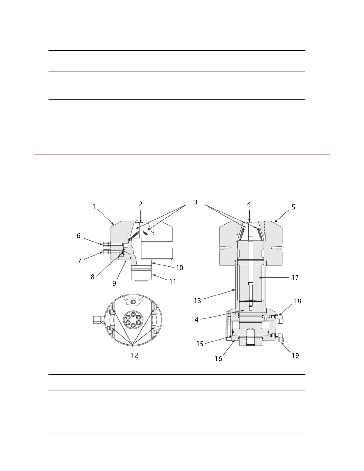
Series 647 Hydraulic Wedge Grips Functional Description
The Series 647 Hydraulic Wedge Grips are typically mounted in an MTS load unit to secure the specimen
under test. Hydraulic pressure to the grips is supplied by and adjusted at an external hydraulic grip supply.
The grips have a side loading design for quick and easy specimen installation.
DescriptionItemDescriptionItem
11Wedge Chamber1
2
only)
12Specimen Guide (flat specimens
Series 647 Hydraulic Wedge Grips Reference Manual 19
Anti-Rotate Adapter (Axial-Torsional
Only)
Anti-Rotate Blocks (Axial-Torsional
Only)
Page 20

Introduction
DescriptionItemDescriptionItem
Cylinder13Wedges3
4
only)
Grip Piston10
Grip Piston14Specimen Guide (flat specimens
Preload Chamber15Wedge Chamber5
End Cap16Hydraulic Release6
Piston Extension17Hydraulic Pressure7
Hydraulic Release18Preload Chamber8
Hydraulic Pressure19End Cap9
About Gripping Specimens
The grips provide a constant, hydraulically actuated gripping force regardless of the applied test loads. The
specimen gripping force is adjustable to prevent specimen damage by the grips or specimen slippage during
the test. Each grip (upper and lower) is independently actuated. When actuated, the preload chamber locks
all moving grip parts in position, thus eliminating backlash when cycling between tension and compression.
The specimen can then be cycled from full tension through zero to full compression with no backlash.
Once a specimen is positioned between the grip wedges, hydraulic pressure is applied to the preload chamber.
This pressure pulls the wedge chamber toward the piston, forcing the wedges to clamp the specimen. The
pressure applied to the preload chamber can be adjusted to a level which clamps the specimen securely, but
does not damage the specimen by applying excessive gripping force.
About Wedges
Each grip model has its own selection of wedges. Not all wedge options are available for all grip models.
Three types of wedges are available for use with the grips: flat wedges, round wedges, and vee-notched
wedges.
• Flat wedges grip flat specimens. Both narrow and wide wedges are available.
• Round wedges can only grip a round specimen of a specific diameter.
• Vee-notched wedges can grip a range of round specimens.
Flat wedge surfaces can be finished with diamond serrations, with a Surfalloy coating, or a smooth finish.
• Diamond serrated surfaces can grip materials such as soft steels and plastics.
• Surfalloy surfaces can grip hard or brittle materials. Surfalloy incorporates a grit onto the wedge surface.
20 Series 647 Hydraulic Wedge Grips Reference Manual
Page 21
• Smooth surfaces can grip specimens that cannot tolerate imperfections on the grip surface. This surface
also has a lower force rating.
Water-cooled wedges are available for applications where the specimen is heated. A water cooling kit includes
the parts to connect the wedges to a water source and regulate the water flow.
About Spiral Washers
The optional Model 601 Spiral Washers are commonly used when installing axial grips. They provide
fatigue-resistant connections between elements of the force train and minimize the effects of backlash.
The spiral washers are placed over the connector studs at each connection and adjusted to place a constant
preload on the stud. The spiral washers also minimize the possibility of backlash due to loose-fitting or worn
stud threads. When cyclic loads below the tensile force level of the preload are applied to the connections,
the load is distributed between the surfaces of the spiral washers and the stud in a ratio of the relative stiffness
of the parts. The spiral washers have a large surface area and therefore greater stiffness. They react to most
of the load and keep the stress in the stud below its fatigue runout level.
Introduction
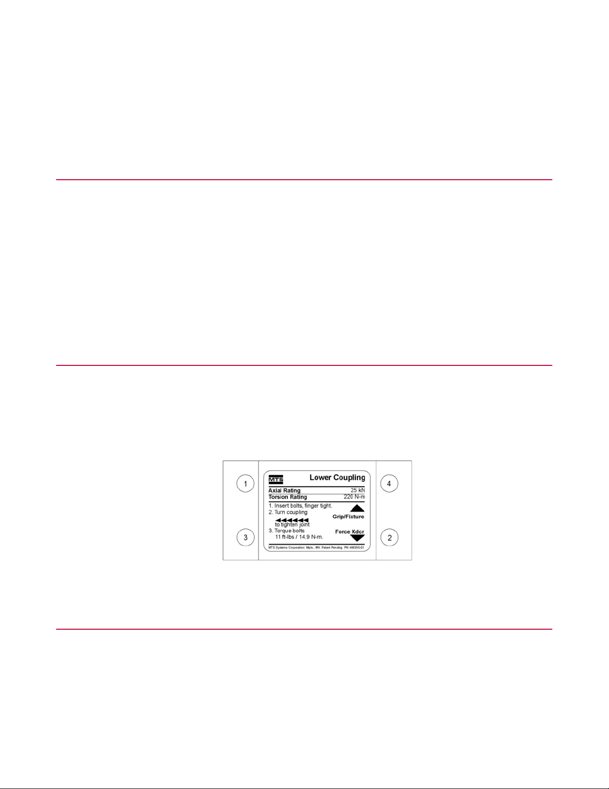
About Couplings
Special upper and lower couplings clamp the grips to the actuator and force transducer for axial-torsional
grips. Each coupling has two different thread patterns—a right-hand thread with a 3 mm pitch, and a left-hand
thread with a 2 mm pitch. Half of the coupling matches the thread of the grip, and the other half matches the
thread of the actuator or force transducer adapter. A label on each coupling indicates the direction to tighten,
torque rotation, and torque requirements. Here is an example:
About All Temperature Grips
The grip mechanism (the wedge chamber and wedges) is fully enclosed in the environmental chamber to
secure the specimen under test. The grip actuating mechanism (the end cap, preload chamber, and piston)
is outside the environmental chamber, eliminating the need for high-temperature hydraulic fluid and allowing
a broader temperature range for testing—from -129° to +315°C (-200° to +600°F) or -129° to +540°C (-200°
to +1000°F) depending on the grip model. With the grip mechanism inside the environmental chamber, the
thermal stresses caused by temperature gradients along the length of the specimen are minimized. The grip
actuating mechanism is water cooled/warmed to further protect it from temperature extremes.
Series 647 Hydraulic Wedge Grips Reference Manual 21
Page 22

Introduction
About Environmental Chambers
The grips can be mounted for room temperature testing or testing in an environmental chamber. The
temperature range of the grips is determined by the type of seals used in the grips and the type of fluid used
for the grips. There are two methods for using grips in an environmental chamber (as shown in the following
figure).
DescriptionItem
Using Extension Rods with Axial GripsA
Using All Temperature GripsB
22 Series 647 Hydraulic Wedge Grips Reference Manual
Page 23

Hydraulic Fluid Recommendations
All frame mounted 3000 psi and 10,000 psi grip supplies use standard Mobile DTE-25 hydraulic fluid from
the HPU. The grips that use this fluid are rated to 65 °C (150 °F) maximum. All other hydraulic grips that are
used within a chamber are rated to maximum of 177 °C (350 °F). These grips require the use of a stand alone
grip supply that uses Mobile SHS 525 hydraulic fluid. This fluid has a flash point and overall temperature
rating higher than 177 °C (350 °F). MTS does not recommend the use of hydraulic grips that have hydraulic
fluid inside chambers rated at higher temperatures.
Cooling Water Specifications
SpecificationParameter
35°C (95°F) maximumTemperature
Introduction
3.8 L/min (1 gpm) minimum, at 0.276 MPa (40 psi)Flow
Quality
Water chemistry is critical for a successful grip cooling. Generally speaking, municipal
drinking water that is pollution free, bacteriologically safe, and has a neutral pH is
perfectly acceptable for grip cooling.
Series 647 Wedge Grip Temperature Ranges
The temperature range of the grips is determined by the type of seals used in the grips and the type of
hydraulic fluid used with the grips. The grips are available in the following temperature ranges:
• -40°C to 177°C (-40°F to 350°F)
• -130°C/315°C (-200°F/600°F)
• -130°C/540°C (-200°F/1000°F)
Not all grip models are available in all temperature ranges.
Series 647 Hydraulic Wedge Grips Reference Manual 23
Page 24

Introduction
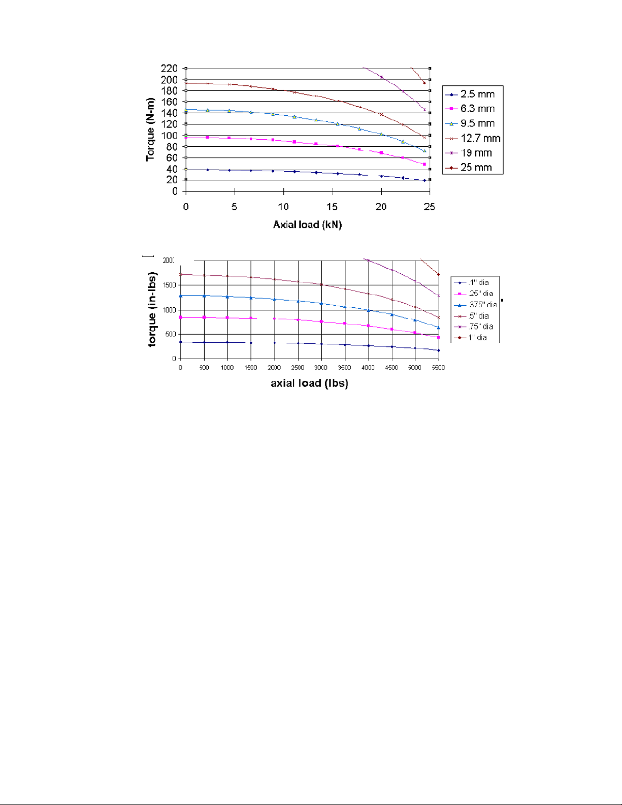
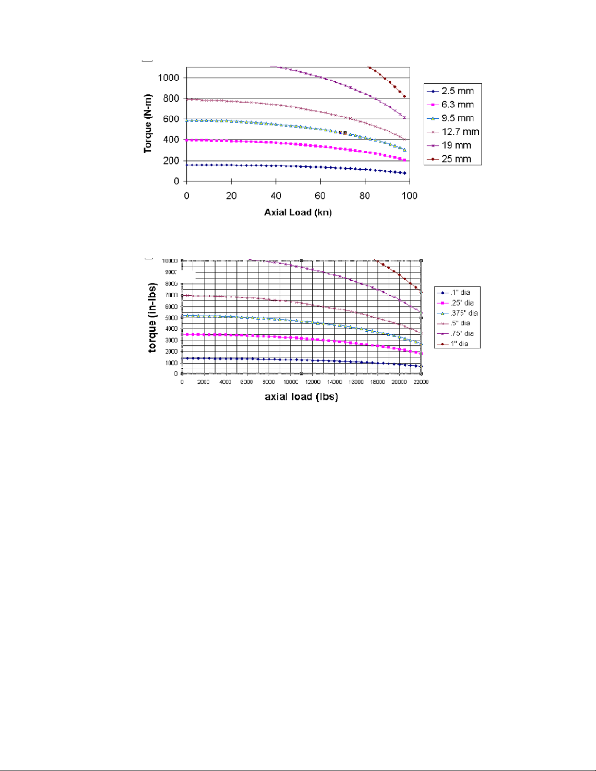
Series 647 Hydraulic Wedge Grip Force and Torque Capacities
The amount of torque the grips can produce is reduced with biaxial operation. The amount of torque is affected
by the amount of axial force and the diameter of the specimen. The graphs, which follow the table, illustrate
the axial-torsional performance envelope of the Model 647.02B and Model 647.10 Hydraulic Wedge Grips
and the Model 647.25 Axial-Torsional Wedge Grips.
Note:
Charts assume that edges for RND specimens are diamond face vee or RND wedges.
Grip PressureDynamic ForceStatic ForceModel
1
2
3
21 MPa (3,000 psi)25 kN (5.5 kip)31 kN (7 kip)647.02B
21 MPa (3,000 psi)100 kN (22 kip)120 kN (27 kip)647.10
69 MPa (10,000 psi)250 kN (55 kip)333 kN (75 kip)647.25
69 MPa (10,000 psi)500 kN (110 kip)550 kN (120 kip)647.50
69 MPa (10,000 psi)1000 kN (220 kip)1200 kN (264 kip)647.100
1
Torsional force for the axial-torsional version is 220 N·m (2,000 in·lb).
2
Torsional force for the axial-torsional version can be 550 N·m (5,000 in·lb) or 1100 N·m (10,000 in·lb).
3
Torsional force for the axial-torsional version is 2200 N·m (20,000 in·lb).
24 Series 647 Hydraulic Wedge Grips Reference Manual
Page 25
Introduction
Model 647.02B Grip Maximum Torque versus Axial Load
Series 647 Hydraulic Wedge Grips Reference Manual 25
Page 26
Introduction
Model 647.10 Grip Maximum Torque versus Axial Load
26 Series 647 Hydraulic Wedge Grips Reference Manual
Page 27

Introduction
Model 647.25 Grip Maximum Torque versus Axial Load
Series 647 Hydraulic Wedge Grips Reference Manual 27
Page 28

Page 29

Safety
Topics:
•
General Safety Practices: Grips and Fixtures........................................................................................30
•
General Precautions for Environmental Components...........................................................................35
•
Hazard Placard Placement....................................................................................................................36
Series 647 Hydraulic Wedge Grips Reference Manual 29
Page 30

Safety
General Safety Practices: Grips and Fixtures
Typically, grips and fixtures are part of equipment used in MTS testing systems. This section provides general
information about safety issues that pertain to systems that use grips and fixtures. These issues include
statements to the intended use and foreseeable misuse of the system and definition for the graphical hazard
labeling that is affixed to your product, and other (more general) safety information that relates to the
high-pressure and high-performance characteristics of MTS servohydraulic and electromechanical systems.
When you prepare to operate a system that includes hydraulic components, ensure the following:
• Do not use or allow personnel to operate the system who are not experienced, trained, or educated in the
inherent dangers associated with high-performance servo hydraulics and who are not experienced, trained,
or educated with regard to the intended operation as it applies to this test system.
• Do not disable safety components or features (including limit detectors, light curtains, or proximity
switches/detectors).
• Do not attempt to operate the system without appropriate personal safety gear (for example, hearing,
hand, and eye protection).
• Do not modify the system or replace system components using parts that are not MTS component parts
or effect repairs using parts or components that are not manufactured to MTS specifications.
• Do not use the system in a test area where uncontrolled access to the test system is allowed when the
system is in operation.
• For servohydraulic systems, do not operate the system unless an interlock is installed to monitor supply
pressure into the HSM and initiate a system interlock if a low or no pressure event occurs.
• Mists of DTE 25 are combustible. Refer to MSDS. Customer is responsible for fire prevention measures
as per facility or building or other local regulations and codes
If you have system related responsibilities (that is, if you are an operator, service engineer, or maintenance
person), you should study safety information carefully before you attempt to perform any test system procedure.
You should receive training on this system or a similar system to ensure a thorough knowledge of your
equipment and the safety issues that are associated with its use. In addition, you should gain an understanding
of system functions by studying the other manuals supplied with your test system. Contact MTS for information
about the content and dates of training classes that are offered.
It is very important that you study the following safety information to ensure that your facility procedures and
the system’s operating environment do not contribute to or result in a hazardous situation. Remember, you
cannot eliminate all the hazards associated with this system, so you must learn and remain aware of the
hazards that apply to your system at all times. Use these safety guidelines to help learn and identify hazards
so that you can establish appropriate training and operating procedures and acquire appropriate safety
equipment (such as gloves, goggles, and hearing protection).
Each test system operates within a unique environment which includes the following known variables:
• Facility variables (facility variables include the structure, atmosphere, and utilities)
• Unauthorized customer modifications to the equipment
• Operator experience and specialization
• Test specimens
30 Series 647 Hydraulic Wedge Grips Reference Manual
Page 31

Because of these variables (and the possibility of others), your system can operate under unforeseen
circumstances that can result in an operating environment with unknown hazards.
Improper installation, operation, or maintenance of your system can result in hazardous conditions that can
cause death, personal injury, or damage to the equipment or to the specimen. Common sense and a thorough
knowledge of the system’s operating capabilities can help to determine an appropriate and safe approach to
its operation.
Warning:
The grips and their components can be heavy, which can make handling them awkward.
Dropping a grip or one of its components can cause injury to personnel and damage to equipment.
Ensure that you take appropriate precautions while moving and positioning the grips and their
components.
Read all manuals
Study the contents of this manual and the other manuals provided with your system before attempting to
perform any system function for the first time. Procedures that seem relatively simple or intuitively obvious
may require a complete understanding of system operation to avoid unsafe or dangerous situations.
Safety
Avoid Pinch and Crush Points
Pinch points exist between the parts of the grip or fixture that contact the specimen. Be aware of these pinch
points when installing a specimen or working around the grip or fixture during test setup. High forces generated
when grip pressure is activated can pinch, cut, or crush anything in the path of the grip/ fixture specimen
contact area and cause serious injury. Stay clear of any potential pinch points.
A crush point exists between the grips. Whenever possible, use tongs or similar tool when handling the
specimen during specimen installation. Never allow any part of your body to enter the path of machine
movement or to touch moving machinery, linkages, hoses, cables, specimens, and so forth. These present
serious crush points or pinch points.
Locate and read hazard placards/labels
Find, read, and follow the hazard placard instructions located on the equipment. These placards are placed
strategically on the equipment to call attention to areas such as known crush points, electrical voltage, and
high pressure hazards.
Series 647 Hydraulic Wedge Grips Reference Manual 31
Page 32

Safety
Know facility safe procedures
Most facilities have internal procedures and rules regarding safe practices within the facility. Be aware of
these safe practices and incorporate them into your daily operation of the system.
Know controls
Before you operate the system for the first time, make a trial run through the operating procedures with the
power off. Locate all hardware and software controls and know what their functions are and what adjustments
they require. If any control function or operating adjustment is not clear, review the applicable information
until you understand it thoroughly.
Know Specimen Properties
The user is responsible for understanding the characteristics of the test specimen. Be sure to use appropriate
personal protective equipment (for example: clothing, hand gloves, eye protection).
Use protective guards such as cages, enclosures, and special laboratory layouts when you work with hazardous
test specimens (for example, brittle or fragmenting materials or materials that are internally pressurized).
Have first aid available
Accidents can happen even when you are careful. Arrange your operator schedules so that a properly trained
person is always close by to render first aid. In addition, ensure that local emergency contact information is
posted clearly and in sight of the system operator.
Be aware of component movement with hydraulics off
The actuator rod can also drift down when hydraulics are turned off hitting anything in its path. This
uncommanded movement is because of oil movement between the pressure/return ports and oil blow by
across the piston hub. Be aware that this can happen and clear the area around the actuator rod when
hydraulics are turned off.
Keep bystanders safely away
Keep bystanders at a safe distance from all equipment. Never allow bystanders to touch specimens or
equipment while the test is running.
Wear proper clothing
Do not wear neckties, shop aprons, loose clothing or jewelry, or long hair that could get caught in equipment
and result in an injury. Remove loose clothing or jewelry and restrain long hair.
Remove flammable fluids
Remove flammable fluids from their containers or from components before you install the container or
component. If desired, you can replace the flammable fluid with a non-flammable fluid to maintain the proper
proportion of weight and balance.
32 Series 647 Hydraulic Wedge Grips Reference Manual
Page 33

Check bolt ratings and torques
To ensure a reliable product, fasteners (such as bolts and tie rods) used in MTS-manufactured systems are
torqued to specific requirements. If a fastener is loosened or the configuration of a component within the
system is modified, refer to information in this product manual to determine the correct fastener, fastener
rating, and torque. Over torquing or under torquing a fastener can create a hazardous situation due to the
high forces and pressures present in MTS test systems.
On rare occasions, a fastener can fail even when it is correctly installed. Failure usually occurs during torquing,
but it can occur several days later. Failure of a fastener can result in a high velocity projectile. Therefore, it
is a good practice to avoid stationing personnel in line with or below assemblies that contain large or long
fasteners.
Lift Equipment Safely
Grips that are too heavy to be lifted by hand are to be lifted with double swivel eyebolts supplied by MTS,
part number 100-263-718.
Warning:
Safety
Large capacity grips are heavy, and must be lifted using hoist rings.
Such grips should be lifted with hoist rings supplied by MTS Systems Corporation.
If hoist rings other than those provided by MTS are used, the customer must ensure that the
other grips are suitable for the purpose.
Practice good housekeeping
Keep the floors in the work area clean. Hydraulic fluid that is spilled on any type of floor can result in a
dangerous, slippery surface. Do not leave tools, fixtures, or other items not specific to the test, lying about
on the floor, system, or decking.
Do not exceed the Maximum Supply Pressure
For hydraulic grips and fixtures. make sure that the hydraulic supply pressure is limited to the maximum
pressure defined by the grip or fixture identification (ID) tag.
Do not disable safety devices
Your system may have active or passive safety devices installed to prevent system operation if the device
indicates an unsafe condition. Do not disable such devices as it may result in unexpected system motion.
Provide adequate lighting
Ensure adequate lighting to minimize the chance of operation errors, equipment damage, and personal injury.
You need to see what you are doing.
Series 647 Hydraulic Wedge Grips Reference Manual 33
Page 34

Safety
Provide means to access out-of-reach components
Make sure you can access system components that might be out of reach while standing on the floor. For
example, ladders or scaffolding might be required to reach load cell connectors on tall load units.
Wear appropriate personal protection
Wear eye protection when you work with high-pressure hydraulic fluid, breakable specimens, or when anything
characteristic to the specimen could break apart.
Wear ear protection when you work near electric motors, pumps, or other devices that generate high noise
levels. Some systems can create sound pressure levels that exceed 70 dbA during operation.
Wear appropriate personal protection equipment (gloves, boots, suits, respirators) whenever you work with
fluids, chemicals, or powders that can irritate or harm the skin, respiratory system, or eyes.
Handle chemicals safely
Whenever you use or handle chemicals (for example, cleaning fluids, hydraulic fluid, batteries, contaminated
parts, electrical fluids, and maintenance waste), refer to the appropriate MSDS documentation for that material
and determine the appropriate measures and equipment required to handle and use the chemical safely.
Ensure that the chemical is disposed of appropriately.
Know system interlocks
Interlock devices should always be used and properly adjusted. Interlock devices are designed to minimize
the chance of accidental damage to the test specimen or the equipment. Test all interlock devices for proper
operation immediately before a test. Do not disable or bypass any interlock devices as doing so could allow
hydraulic pressure to be applied regardless of the true interlock condition. The Reset/Override button is a
software function that can be used to temporarily override an interlock while attempting to gain control of the
system.
Know system limits
Never rely on system limits such as mechanical limits or software limits to protect you or any personnel.
System limits are designed to minimize the chance of accidental damage to test specimens or to equipment.
Test all limits for proper operation immediately before a test. Always use these limits and adjust them properly.
Do not disturb sensors
Do not bump, wiggle, adjust, disconnect, or otherwise disturb a sensor (such as an accelerometer or
extensometer) or its connecting cable when hydraulic pressure is applied.
Ensure secure cables
Do not change any cable connections when electrical power or hydraulic pressure is applied. If you attempt
to change a cable connection while the system is in operation, an open control loop condition can result. An
open control loop condition can cause a rapid, unexpected system response which can result in severe
personal injury, death, or damage to equipment. Also, ensure that all cables are connected after you make
any changes in the system configuration.
34 Series 647 Hydraulic Wedge Grips Reference Manual
Page 35

Stay alert
Avoid long periods of work without adequate rest. In addition, avoid long periods of repetitious, unvarying, or
monotonous work because these conditions can contribute to accidents and hazardous situations. If you are
too familiar with the work environment, it is easy to overlook potential hazards that exist in that environment.
Contain small leaks
Do not use your fingers or hands to stop small leaks in hydraulic or pneumatic hoses. Substantial pressures
can build up, especially if the hole is small. These high pressures can cause the oil or gas to penetrate your
skin, causing painful and dangerously infected wounds. Turn off the hydraulic supply and allow the hydraulic
pressure to dissipate before you remove and replace the hose or any pressurized component.
Stay clear of moving equipment/avoid crush points
Stay clear of mechanical linkages, connecting cables, and hoses that move because you can get pinched,
crushed, tangled, or dragged along with the equipment. High forces generated by the system can pinch, cut,
or crush anything in the path of the equipment and cause serious injury. Stay clear of any potential crush
points. Most test systems can produce sudden, high-force motion. Never assume that your reactions are fast
enough to allow you to escape injury when a system fails.
Safety
Know the causes of unexpected actuator motions
The high force and velocity capabilities of MTS actuators can be destructive and dangerous (especially if
actuator motion is unexpected). The most likely causes of unexpected actuator response are operator error
and equipment failure due to damage or abuse (such as broken, cut, or crushed cables and hoses; shorted
wires; overstressed feedback devices; and damaged components within the servocontrol loop). Eliminate
any condition that could cause unexpected actuator motion.
General Precautions for Environmental Components
Observe the following precautions when operating the grips:
• Make sure controller detectors are set to minimize the chance of the grip contacting the furnace. Generally
this involves setting displacement limits to restrict actuator rod travel.
• When positioning the crosshead during specimen installation, be careful not to allow contact of machine
components with the environmental chamber or furnace. Machine components can include grips, attachment
kits, the crosshead, pullrods, and other related items.
• Be sure to read and understand the safety data sheets of the materials, chemicals, and fluids used regarding
any combustibility and toxicity characteristics.
• After operation at elevated temperature, be sure to allow components to cool before handling. Components
can include grips, specimen, environmental chamber or furnace surfaces.
Series 647 Hydraulic Wedge Grips Reference Manual 35
Page 36

Safety
• Use protective gear (such as gloves) if it is necessary to handle hot objects. Hot objects can include
specimens tested at elevated temperatures or furnace surfaces.
• When using an environmental chamber or furnace, be aware of possible crush points between the grip
and any attachment fixture and the chamber or furnace.
Hazard Placard Placement
Hazard placards contain specific safety information and are affixed directly to the system so they are plainly
visible.
Each placard describes a system-related hazard. When possible, international symbols (icons) are used to
graphically indicate the type of hazard and the placard label indicates its severity. In some instances, the
placard may contain text that describes the hazard, the potential result if the hazard is ignored, and general
instructions about how to avoid the hazard.
The following labels are typically located on the grips.
Part # 47-081-201
Part # 47-469-701
Each label contains the following information:
• Model number
• Part number
• Serial number
• Revision level
• Temperature range
• Force capacity
• Maximum pressure
Note:
The two versions of this label have different pressure and force ratings.
36 Series 647 Hydraulic Wedge Grips Reference Manual
Page 37

Installation
Topics:
•
Series 647 Hydraulic Grip Lift Points.....................................................................................................38
•
Install Axial Grips...................................................................................................................................39
•
Install Axial-Torsional Grips...................................................................................................................44
•
Install 647.250 Grips..............................................................................................................................50
•
Install the Grips in an Environmental Chamber.....................................................................................50
•
Install Extension Rods...........................................................................................................................66
•
Align the Wedge Openings....................................................................................................................71
•
Preload the Spiral Washers...................................................................................................................72
•
Grip Water Cooling Configurations........................................................................................................74
Series 647 Hydraulic Wedge Grips Reference Manual 37
Page 38

Installation
Series 647 Hydraulic Grip Lift Points
647.01 through 647.100
DescriptionItem
Two holes 180° apartA
ThreadModel
None. Lift by hand.647.01/02
M10 X 1.5 5/8” DP647.10
M10 X 1.5 5/8” DP647.25
M10 X 1.5 5/8” DP647.50
M10 X 1.5 5/8” DP647.100
38 Series 647 Hydraulic Wedge Grips Reference Manual
Page 39

647.250
Installation
DescriptionItem
Bottom ViewA
Install Axial Grips
About the Installation of Axial Grips
Grip installation in a load unit force train involves attaching one grip onto the end of the actuator rod and one
grip to the force transducer. The grips are mounted to the load unit with conductor studs.
The following figure shows the components used for most installations.
Series 647 Hydraulic Wedge Grips Reference Manual 39
Page 40

Installation
Axial Grip Installation Components
DescriptionItem
Crosshead or Force Transducer1
Spiral Washer Set2
Stud3
Shim Washer4
Shim Washer5
Actuator Rod6
Load Unit Base Plate7
Spiral Washer Set8
Stud9
Required equipment
The following materials and equipment are required for installation:
• The appropriate attachment kit.
• Two sets of spiral washers.
• Two connector studs.
• Shim washers.
• Lubricant.
40 Series 647 Hydraulic Wedge Grips Reference Manual
Page 41

Installation
• Appropriately sized double swivel eyebolts, adequately sized wood blocks and plywood sheet (or equivalent),
and an appropriately sized lifting device.
Shims
If a specific orientation of the grips is required, shims are typically used to achieve that desired orientation.
Use the following table to determine the proper shims.
Shim Specifications
Number
(Kit
number)
RevPart
A521050-02
Thread
Size
1/2"-20A521050-01
M12 x
1.25 mm
1/2"-20A521050-03
Actuator
(OD)
(1.12)
(1.12)
(1.62)
Ref.
travel of
full th'd
Approx.
1/2 turn
(180º)
Shim
Number
Thickness
Qty
Approx.
1/4 turn
(90º)
Shim
Number
Thickness
Qty
Approx.
1/8 turn
(45º)
Shim
Number
Thickness
Qty
Approx.
1/16 turn
(22.5º)
Shim
Number
Thickness
Qty
Approx.
full turn
(360º)
Shim
Number
Thickness
Qty
443665-14443665-18]443665-13443665-17443665-16.050"358 act
.004.003.006.012.025
11111
443665-18443665-18]443665-13443665-17443665-16.049"358 act
.003.003.006.012.025
11111
443665-03443665-21443665-07443665-20443665-19.050"318 act
.004.003.006.012.025
11111
A521050-04
A521050-06
M12 x
1.25 mm
1"-14A521050-05
M27 x 2
mm
1-1/2"-12A521050-07
(1.62)
(2.62)
(2.62)
(3.62)
443665-24443665-21443665-07443665-20443665-19.049"318 act
.003.003.006.012.025
11111
443665-25443665-25443665-24443665-24443665-22.071"318 act
.005.005.009.009.035
11121
443665-25443665-25443665-24443665-23443665-23.079"318 act
.005.005.009.02.02
11112
443665-27443665-02443665-02443665-26443665-26.083"318 act
.005.006.006.02.02
11212
Series 647 Hydraulic Wedge Grips Reference Manual 41
Page 42

Installation
Number
(Kit
number)
RevPart
A521050-08
A521050-10
Thread
Size
M36 x 2
mm
2"-12A521050-09
M52 x 2
mm
Actuator
(OD)
(3.62)
(4.62)
(4.62)
Ref.
travel of
full th'd
Approx.
1/2 turn
(180º)
Shim
Number
Thickness
Qty
Approx.
1/4 turn
(90º)
Shim
Number
Thickness
Qty
Approx.
1/8 turn
(45º)
Shim
Number
Thickness
Qty
Approx.
1/16 turn
(22.5º)
Shim
Number
Thickness
Qty
Approx.
full turn
(360º)
Shim
Number
Thickness
Qty
443665-27443665-27443665-27443665-26443665-26.079"318 act
.005.005.005.02.02
11212
443665-29443665-29443665-15443665-28443665-28.083"318 act
.005.005.01.02.02
21112
443665-29443665-29443665-15443665-28443665-28.079"318 act
.005.005.01.02.02
11112
Install Axial Grip
The following procedure assumes that the actuator is mounted in the base of the load unit and the force
transducer is mounted to the crosshead. If you have a load unit with the actuator mounted to the crosshead,
make the appropriate changes to the following procedure.
1.
Warning:
Grip installation is dangerous because it occurs within the crush zone of the force train while
full hydraulic pressure is applied and actuator movement is required during the installation.
Unexpected actuator movement can cause personal injury and damage to the equipment.
Take every precaution to avoid unexpected actuator movement while installing the grips.
Set up the load unit.
a) Turn on the system hydraulic pressure.
b) Adjust the actuator and crosshead position as necessary to allow adequate room to install the grips.
c) Turn the hydraulic pressure off.
Ensure that system hydraulic pressure has been reduced to zero before proceeding. To do this, turn
off the hydraulic power unit and exercise the actuator until it stops moving.
d) Lubricate all of the surfaces that will contact each other (screw threads, spacers, and so forth)
42 Series 647 Hydraulic Wedge Grips Reference Manual
Page 43

Installation
2. Mount the lower grip to the actuator piston rod. Thread the stud into the lower grip. The connector stud
should turn freely. If any resistance is encountered, disassemble and correct the problem before proceeding.
a) Add any required shims, spacer, or spiral washers to the stud.
Note:
The attachment kit drawing shows what components (such as shims, spiral washers, etc.) should
be installed.
b) Position the lower grip to align it with the connecting stud and stabilize the grip.
• Place appropriately sized wood blocks across the load unit base plate, on opposite sides of the
actuator piston rod.
• For heavy grips, insert the double swivel eyebolts into the threaded holes provided on the grip
chamber. Attach a lifting device to the double swivel eyebolts and carefully raise the grip.
c) Turn on hydraulic pressure and raise the actuator rod until it just makes contact with the connector
stud. Reposition the grip, as necessary, to center the stud over the actuator rod.
d) Slowly screw the grip into the actuator rod, raising the actuator rod as you go, until it is snug. The
connector stud should turn freely. If any resistance is encountered, disassemble and correct the problem
before proceeding.
e) Turn the hydraulic pressure off.
Ensure that system hydraulic pressure has been reduced to zero before proceeding. To do this, turn
off the hydraulic power unit and exercise the actuator until it stops moving.
3. Mount the upper grip to the force transducer on the crosshead.
Note:
Ensure that the force transducer is properly aligned (see your load unit manual).
a)
Warning:
The upper grips are very top heavy and will have a tendency to tip over when lifted by the
double swivel eyebolts.
Dropped grips can cause injury to personnel and damage to equipment.
Never attempt to control the grip by holding onto the eyebolts. Use the connector stud to
help control the grip balance.
Thread a stud into the upper grip.
b) Place a wooden spacer (a wood block or piece of plywood) on top of the lower grip. The wooden spacer
should be large enough to cover the diameter of the grip.
Note:
The upper grip might need help to balance it on the wooden spacer on the lower grip.
c) Carefully position the grip on top of the wooden spacer on the lower grip.
Series 647 Hydraulic Wedge Grips Reference Manual 43
Page 44

Installation
You might need to insert the double swivel eyebolts into the threaded holes on the grip chamber. Attach
a lifting device to the double swivel eyebolts and position the grip on top of the lower grip.
Important:
NO STANDARD EYEBOLTS should be used to lift the grip.
d) With the connector stud facing up, add any required shims, spacers, or spiral washers to the stud.
e) Turn on hydraulic pressure and slowly raise the lower grip until the stud on the upper grip just makes
contact with the force transducer. Reposition the grip as necessary for proper thread alignment.
f) Slowly screw the grip into the force transducer until it is snug.
4. Align the grip wedge openings.
Check the alignment between the upper and lower grips.
Align the lower grip as necessary for the desired hose connection and wedge opening orientation. If the
actuator rod cannot be rotated, remove the lower grip and install one or more shim washers between the
spiral washers and the lower element of the force train. Reinstall the grip.
Align the upper grip wedge opening with the lower grip wedge opening. If proper alignment is not possible,
remove the upper grip and install one or more shim washers between the spiral washers and the upper
element of the force train. Reinstall the grip.
5. Connect the hydraulics.
Turn the hydraulic pressure off. Ensure that system hydraulic pressure has been reduced to zero before
proceeding. To do this, turn off the hydraulic power unit and exercise the actuator until it stops moving.
Using the provided hydraulic hoses, make connections between the pressure and release ports on the
grip and the pressure and release ports on the load unit or the external hydraulic grip supply. See your
load unit product manual or hydraulic grip control manual for their port locations.
6. Tighten the grips.
See the appropriate procedure and preload the connector stud and return to this procedure when done.
7. Install the wedges.
See the appropriate procedure to install wedges into the grips.
Install Axial-Torsional Grips
About the Installation of Axial-Torsional Grips
Grip installation in a load unit force train involves attaching one grip onto the end of the actuator rod and one
grip to the force transducer or crosshead. The grips are mounted to the load unit with conductor studs.
The following figure shows the components used for most installations.
44 Series 647 Hydraulic Wedge Grips Reference Manual
Page 45

Installation
Required equipment
Axial-Torsional Grip Installation Components
DescriptionItemDescriptionItem
Crosshead10Adapter1
Force Transducer11Socket Head Cap Screw2
Left Hand Thread12Upper Coupling3
Right Hand Thread13Release Pressure4
Upper Grip14Clamp Pressure5
Lower Grip15Release Pressure6
Left Hand Thread16Clamp Pressure7
Right Hand Thread17Lower Coupling8
Load Unit Base Plate18Actuator Rod9
The following materials and equipment are required for installation:
• The appropriate attachment kit (includes a drawing showing what components should be installed).
Series 647 Hydraulic Wedge Grips Reference Manual 45
Page 46

Installation
• Lubricant.
• Appropriately sized double swivel eyebolts, adequately sized wood blocks and plywood sheet (or equivalent),
and an appropriately sized lifting device.
Important:
NO STANDARD EYEBOLTS should be used to lift the grip.
Install Axial-Torsional Grip
If you are installing the grip on an axial-torsional force transducer, perform the force transducer alignment
procedure before proceeding (see the appropriate load unit product manual).
The following procedure assumes that the actuator is mounted in the base of the load unit and the force
transducer is mounted to the crosshead. If you have a load unit with the actuator mounted to the crosshead,
make the appropriate changes to the following procedure.
For an assembly reference, see Axial-Torsional Grip Installation Components on page 45.
Note:
Although it is possible for the grips to be installed by one person, we recommend using two people to
lift, handle, and position the grips.
1.
Warning:
Grip installation is dangerous because it occurs within the crush zone of the force train while
full hydraulic pressure is applied and actuator movement is required during the installation.
Unexpected actuator movement can cause personal injury and damage to the equipment.
Take every precaution to avoid unexpected actuator movement while installing the grips.
Set up the load unit.
a) Turn on the system hydraulic pressure.
b) Adjust the actuator and crosshead position as necessary to allow adequate room to install the grips.
c) Select rotation control and adjust the actuator to the mid-rotation position.
d) Turn the hydraulic pressure off.
e) Ensure that system hydraulic pressure has been reduced to zero before proceeding. To do this, turn
off the hydraulic power unit and exercise the actuator until it stops moving.
f) Clean and lubricate all of the surfaces that will contact each other (screw threads, spacers, and so
forth)
g) Clean the surfaces with alcohol or similar decreasing solvent. Lubricate the parts with Molykote G-n
paste.
2. Mount the lower grip to the actuator piston rod using the actuator-to-grip coupling.
46 Series 647 Hydraulic Wedge Grips Reference Manual
Page 47

Installation
a) Remove the socket head cap screws from the lower coupling and place the screws and coupling halves
within easy reach and oriented properly for installation on the grips.
Note:
The label on the coupling indentifies which component should be connected to each side of the
coupling. Each end of the coupling has different threads.
b) Position the lower grip to align it with the connecting stud and stabilize the grip.
• Place appropriately sized wood blocks across the load unit base plate, on opposite sides of the
actuator piston rod.
• For heavy grips, insert the double swivel eyebolts into the threaded holes provided on the grip
chamber. Attach a lifting device to the double swivel eyebolts and carefully raise the grip.
c) Select the lower grip coupling set. Place the lower grip coupling half with the threaded holes against
the actuator and grip threads. Rotate it back and forth, as necessary, until the threads mesh with the
actuator and grip threads.
d) Place the other coupling half against the actuator and grip threads. While holding the two halves together
thread the socket head cap screws into the coupling until they are finger tight.
e) Check both ends of the coupling to ensure that the gap between the two halves is approximately equal.
If necessary, tighten and loosen the socket head cap screws to achieve this.
f) Find the label on the coupling. This label indicates the direction to tighten, the rotation pattern for
tightening the cap screws, and other important information. The illustration is an example only.
g) With all the socket head cap screws finger tight, rotate the coupling assembly in the direction shown
on the coupling label until it is tight. This preloads the grip connection.
h) Tighten the socket head cap screws in the order shown on the coupling label, first to 10%, then to 50%,
and finally to 100% of the specified torque.
DescriptionItem
Numbers show the rotation pattern.1
Full (100%) torque listed here.2
Series 647 Hydraulic Wedge Grips Reference Manual 47
Page 48

Installation
3.
Warning:
The upper grips are very top heavy and will have a tendency to tip over when lifted by the
double swivel eyebolts.
Dropped grips can cause injury to personnel and damage to equipment.
Never attempt to control the grip by holding onto the eyebolts. Use the connector stud to help
control the grip balance.
Mount the upper grip to the force transducer on the crosshead using an adapter between the force
transducer and the upper grip.
a) Place the load transducer mating adapter against the force transducer and thread the socket head cap
screws into the force transducer until they are finger tight.
b) Using the sequence shown in the figure to the right, torque the socket head screws first to 10%, then
to 50%, and finally to 100% of the torque specified on the attachment kit drawing (MTS part number
469615-xx).
c) Remove the socket head cap screws from the upper coupling and place the screws and coupling halves
within easy reach and oriented properly for installation on the grips.
d) Place a wooden spacer (a wood block or piece of plywood) on top of the lower grip. The wooden spacer
should be large enough to cover the diameter of the grip.
48 Series 647 Hydraulic Wedge Grips Reference Manual
Page 49

DescriptionItemDescriptionItem
Wood Block7Load Unit Crosshead1
Lower Grip8Force Transducer2
Lower Coupling9Adapter Plate3
Actuator Piston Rod10Upper Coupling4
Load Unit Base Plate11Upper Grip5
Load Unit Columns6
e) Carefully position the grip on top of the wooden spacer on the lower grip.
Note:
You will need to construct a proper support or have someone available to help balance the upper
grip on the lower grip.
Installation
f) You might need to insert double swivel eyebolts into the threaded holes on the grip chamber. Attach
a lifting device to the double swivel eyebolts and position the grip on top of the lower grip.
g) Select the upper coupling set. Place the coupling half with the threaded holes against the adapter and
grip threads. Rotate it back and forth, as necessary, until the threads mesh with the actuator and grip
threads.
h) Place the other coupling half against the actuator and grip threads. While holding the two halves
together, thread the socket head cap screws into the coupling until they are finger tight.
i) Check both ends of the coupling to ensure that the gap between the two halves is approximately equal.
If necessary, tighten and loosen the socket head cap screws to achieve this.
4. Tighten the grips.
a) Find the label on the coupling. This label shows the direction to tighten, the rotation pattern for tightening
the cap screws, and other important information. The illustration is an example only.
b) With all of the socket head cap screws finger tight, rotate the coupling assembly in the direction shown
on the label until it is tight. This is essential to ensure proper preloading of the coupling.
c) Tighten the socket head cap screws in the rotation pattern shown on the label, first to 10%, then to
50%, and finally to 100% of the torque specified on the label.
Series 647 Hydraulic Wedge Grips Reference Manual 49
Page 50

Installation
DescriptionItem
Numbers show the rotation pattern.1
Full (100%) torque listed here.2
5. Connect the hydraulics.
Using the provided hydraulic hoses, make connections between the pressure and release ports on the
grip and the pressure and release ports on the load unit or the external hydraulic grip supply. See the your
load unit product manual or hydraulic grip control manual for their port locations.
6. Install the wedges.
See the appropriate procedure to install wedges into the grips.
Install 647.250 Grips
Warning:
The grips and their components can be heavy, which can make handling them awkward.
Dropping a grip or one of its components can cause injury to personnel and damage to equipment.
Ensure that you take appropriate precautions while moving and positioning the grips and their
components.
Installation of Model 647.250 Grips varies depending on system configuration. Contact MTS for additional
information. However, there are some considerations that are common to all installations:
• You typically need swivel hoist rings screwed into the provided threaded holes to attach a lifting device.
• It is recommended to have an overhead lifting device or fork lift that can support the weight of the grip.
Important:
NO STANDARD EYEBOLTS should be used to lift the grip.
Install the Grips in an Environmental Chamber
About Installation of the Grips in an Environmental Chamber
The all-temperature grips are designed to be used over a wide range of temperatures. To achieve a given
temperature, an environmental chamber is needed. Environmental chambers are available with or without
U-plugs. A Uplug is a removable panel that allows the chamber to be installed after the grips are installed.
50 Series 647 Hydraulic Wedge Grips Reference Manual
Page 51

Installation
• If the environmental chamber has upper and lower U-plugs, install the grips first, then install the
environmental chamber. Simply remove the U-plugs from the chamber, move the environmental chamber
around the grips, and reinstall the U-plugs (see Install Environmental Chambers with U-Plugs on page
51).
DescriptionItem
Lower U-plug1
• If the environmental chamber has no U-plugs, the environmental chamber must installed first. Then the
grips must be partially disassembled and reassembled after the environmental chamber is installed (see
Install Environmental Chambers Without U-Plugs on page 55).
Note:
See the environmental chamber product manual for additional information.
Required equipment
Equipment and materials required to install the all-temperature grips include:
• The appropriate attachment kit includes the components to install the grips
• Appropriately sized device to lift the heavier grips
• Appropriately sized double swivel eyebolts and wood blocks or plywood sheet for lifting the heavier grips
• Lubricant
• Hydraulic plumbing capable of withstanding the temperature extremes
• An environmental chamber
• A heating/cooling kit
• A tool kit is provided with each set of grips. It contains a set of spare extension springs for securing the
wedges in the grip, a utility hook, the tools required to disassemble the grip, and eye bolts and a swivel
eye for installing and removing the grips.
Install Environmental Chambers with U-Plugs
The following procedure assumes the actuator is mounted in the base of the load unit and that the force
transducer is mounted to the crosshead. If you have a load unit with the actuator mounted to the crosshead,
make the appropriate changes to the following procedure.
For an assembly reference, see Axial-Torsional Grip Installation Components on page 45.
Series 647 Hydraulic Wedge Grips Reference Manual 51
Page 52

Installation
Environmental chambers that have U-plugs can be installed after the grips are installed. The following figure
shows the components used for most installations.
All-Temperature Grip Installation Components
52 Series 647 Hydraulic Wedge Grips Reference Manual
DescriptionItemDescriptionItem
Hydraulic Release10Shim Washer1
Hydraulic Pressure11Connector Stud2
Upper Grip Assembly12Environmental Chamber3
Lower Grip Assembly13Water Supply4
Hydraulic Release14Shim Washer5
Hydraulic Pressure15Actuator Rod6
Connector Stud16Load Unit Base Plate7
Spiral Washer Set17Force Transducer8
Page 53

Installation
DescriptionItemDescriptionItem
Spiral Washer Set9
1.
Warning:
Grip installation is dangerous because it occurs within the crush zone of the force train while
full hydraulic pressure is applied and actuator movement is required during the installation.
Unexpected actuator movement can cause personal injury and damage to the equipment.
Take every precaution to avoid unexpected actuator movement while installing the grips.
Set up the load unit.
a) Turn on the system hydraulic pressure.
b) Adjust the actuator and crosshead positions as necessary to create adequate room to install the grips.
c) Turn the hydraulic pressure off.
Ensure that system hydraulic pressure has been reduced to zero before proceeding. To do this, turn
off the hydraulic power unit and exercise the actuator until it stops moving.
d) Clean and lubricate all of the surfaces that will contact each other (screw threads, spacers, and so
forth).
2. Mount the lower grip to the actuator piston rod using the appropriate stud, shims, spacer, or spiral washers.
a) Place a small piece of compliant material in the threaded hole of the grip and thread the stud into the
lower grip.
The connector stud should turn freely. If any resistance is encountered, disassemble and correct the
problem before proceeding.
b) Add any required shims, spacer, or spiral washers to the stud.
The attachment kit drawing shows what components (such as shims, spiral washers, and so forth)
should be installed.
c) Position the lower grip to align it with the connecting stud and stabilize the grip.
• Place appropriately sized wood blocks across the load unit base plate, on opposite sides of the
actuator piston rod.
• For heavy grips, insert the double swivel eyebolts into the threaded holes provided on the grip
chamber. Attach a lifting device to the double swivel eyebolts and carefully raise the grip.
d) Turn on hydraulic pressure and raise the actuator rod until it just makes contact with the connector
stud. Reposition the grip, as necessary, to center the stud over the actuator rod.
e) Slowly screw the grip into the actuator rod, raising the actuator rod as you go, until it is snug.
The connector stud should turn freely. If any resistance is encountered, disassemble and correct the
problem before proceeding.
Series 647 Hydraulic Wedge Grips Reference Manual 53
Page 54

Installation
f) Turn the hydraulic pressure off.
Ensure that system hydraulic pressure has been reduced to zero before proceeding. To do this, turn
off the hydraulic power unit and exercise the actuator until it stops moving.
3.
Warning:
The upper grips are very top heavy and will have a tendency to tip over when lifted by the
double swivel eyebolts.
Dropped grips can cause injury to personnel and damage to equipment.
Never attempt to control the grip by holding onto the eyebolts. Use the connector stud to help
control the grip balance.
Mount the upper grip to the force transducer on the crosshead using the appropriate stud, shims, spacer,
or spiral washers. SeeAxial-Torsional Grip Installation Components on page 45.
Note:
Ensure that the force transducer is properly aligned (see your load unit manual).
a) Thread the stud into the upper grip.
b) Place a wooden spacer (a wood block or piece of plywood) on top of the lower grip. The wooden spacer
should be large enough to cover the diameter of the grip.
Note:
You will need to construct a proper support or have someone available to help balance the upper
grip on the lower grip.
c) Carefully position the grip on top of the wooden spacer on the lower grip.
You might need to insert the double swivel eyebolts into the threaded holes on the grip chamber. Attach
a lifting device to the double swivel eyebolts and position the grip on top of the lower grip.
d) With the connector stud facing up, add any required shims, spacers, or spiral washers to the stud.
e) Turn on hydraulic pressure and slowly raise the lower grip until the stud on the upper grip just makes
contact with the force transducer. Reposition the grip, as necessary, for proper thread alignment.
f) Slowly screw the grip into the force transducer until it is snug.
4. Align the grip wedge openings. See “Align the Wedge Openings” for more information.
Align the lower grip as necessary for the desired hose connection and wedge opening orientation. If the
actuator rod cannot be rotated, remove the lower grip and install one or more shim washers between the
spiral washers and the lower element of the force train. Reinstall the grip (go to Step 2).
Align the upper grip wedge opening with the lower grip wedge opening. If proper alignment is not possible,
remove the upper grip and install one or more shim washers between the spiral washers and the upper
element of the force train. Reinstall the grip (go to Step 3).
5. Connect the hydraulics.
54 Series 647 Hydraulic Wedge Grips Reference Manual
Page 55

Installation
Turn the hydraulic pressure off. Ensure that system hydraulic pressure has been reduced to zero before
proceeding. To do this, turn off the hydraulic power unit and exercise the actuator until it stops moving.
Using the provided hydraulic hoses, make connections between the pressure and release ports on the
grip and the pressure and release ports on the load unit or on the external hydraulic grip supply. See your
load unit product manual or hydraulic grip control manual for their port locations.
6. If needed, connect the water supply. Water can heat or cool the grips.
a) Mount the water valve clamp to a load unit column.
b) Connect water lines (supply and drain) between the water lines attached to the columns and the upper
and lower grips.
c) Connect the water supply (and drain) to the water valve/drain mounted to the load unit columns.
7. Tighten the grips.
See “Preload the Spiral Washers” to preload the connector stud. Return to this procedure when done.
8. Install the environmental chamber.
Position the environmental chamber (with its cart) in the load unit so that the actuator extends through the
chamber’s U-plugs. Secure the cart and install the U-plugs. Refer to the environmental chamber
documentation for more information.
9. Install the wedges.
Go to “Change Wedges 647.02 - 647.100” for the procedure to install wedges into the grips.
Install Environmental Chambers Without U-Plugs
Environmental chambers that do not have U-plugs must be installed before the grips are installed. The grips
must be partially disassembled to install them. The following figure shows the components of the grip assembly.
Series 647 Hydraulic Wedge Grips Reference Manual 55
Page 56

Installation
All-Temperature Grip Component Assemblies
DescriptionItemDescriptionItem
Eye Bolt Holes (2)5Hydraulic Chamber1
Wedge Chamber6Cylinder2
Socket Head Bolt7Piston Extension3
Eye Bolt Holes (4)4
The following table lists the approximate weights for the components of the all-temperature grips.
LocationModel
Chamber
CylinderWedge
Piston
Extension
Hydraulic
Chamber
Assembled
Weight
15 kg (33 lb)5.1 kg (11 lb)3 kg (6 lb)1.3 kg (3 lb)6 kg (13 lb)top647.02
17 kg (38 lb)5.1 kg (11 lb)4 kg (9 lb)2 kg (4.5 lb)6 kg (13 lb)bottom
57 kg (125 lb)16 kg (34 lb)7 kg (16 lb)3 kg (7 lb)24 kg (52 lb)top647.10
56 Series 647 Hydraulic Wedge Grips Reference Manual
Page 57

Installation
LocationModel
Chamber
647.25
The following procedure assumes the actuator is mounted in the base of the load unit and the force transducer
is mounted to the crosshead. If you have a load unit with the actuator mounted to the crosshead, make the
appropriate changes to the following procedure.
For an assembly reference, see Axial-Torsional Grip Installation Components on page 45.
1.
top
bottom
72 kg (158 lb)
72 kg (158 lb)
CylinderWedge
5 kg (11 lb)
7 kg (16 lb)
Piston
Extension
17 kg (37 lb)
24 kg (53 lb)
Hydraulic
Chamber
37 kg (82 lb)
37kg (82 lb)
Assembled
Weight
64 kg (142 lb)16 kg (34 lb)12 kg (26 lb)5 kg (11 lb)24 kg (52 lb)bottom
131 kg (288
lb)
141 kg (310
lb)
Warning:
Grip installation is dangerous because it occurs within the crush zone of the force train while
full hydraulic pressure is applied and actuator movement is required during the installation.
Unexpected actuator movement can cause personal injury and damage to the equipment.
Take every precaution to avoid unexpected actuator movement while installing the grips.
Warning:
The grips and their components can be heavy, which can make handling them awkward.
Dropping a grip or one of its components can cause injury to personnel and damage to
equipment.
Ensure that you take appropriate precautions while moving and positioning the grips and their
components.
Set up the load unit.
a) Turn on the system hydraulic pressure.
b) Position the actuator and crosshead as necessary to allow adequate room to install the grips.
c) Turn the hydraulic pressure off.
d) Ensure that system hydraulic pressure has been reduced to zero before proceeding. To do this, turn
off the hydraulic power unit and exercise the actuator until it stops moving.
2. Disassemble the grips.
a) Place both grips on a clean work surface near the load unit.
Note the difference in length. The longer grip is the lower grip and the shorter grip is the upper grip.
Lay both grips on their side and block, as necessary, to prevent them rolling while being worked on.
Series 647 Hydraulic Wedge Grips Reference Manual 57
Page 58

Installation
b) If necessary, remove the wedges from each grip. Go to “Change Wedges 647.02 - 647.100” and return
to this procedure when done.
c) Separate the hydraulic chamber from the grip assembly. Remove the socket head bolt which secures
the piston extension to the hydraulic chamber. Perform this step for both grips.
d) If necessary attach a strap wrench to the cylinder and the hydraulic chamber. Unscrew the hydraulic
chamber from the cylinder. Perform this step for both grips.
e) Clean and lubricate all of the surfaces that will contact each other (screw threads, spacers, and so
forth).
f) Clean the surfaces with alcohol or similar decreasing solvent. See “Temperature ranges” for the
recommended lubricant.
3. Mount the hydraulic chamber of the lower grip to the actuator piston rod using the appropriate stud, shims,
and spiral washers.
DescriptionItemDescriptionItem
Load Unit Columns5Hydraulic Chamber1
Lifting Device6Connector Stud2
Spiral Washers7Shim Washer3
Actuator Rod8Load Unit Base Plate4
a) Thread the connector stud into the hydraulic chamber of the lower grip. The connector stud should turn
freely. If any resistance is encountered, disassemble and correct the problem before proceeding.
b) Add any required shims, spacer, or spiral washers to the stud.
The attachment kit drawing shows what components (such as shims, spiral washers, and so forth)
should be installed.
c) Position the lower grip to align it with the connecting stud and stabilize the grip.
• Place appropriately sized wood blocks across the load unit base plate, on opposite sides of the
actuator piston rod.
• For heavy grips, insert the double swivel eyebolts into the threaded holes provided on the grip
chamber. Attach a lifting device to the double swivel eyebolts and carefully raise the grip.
58 Series 647 Hydraulic Wedge Grips Reference Manual
Page 59

d) Turn on hydraulic pressure and raise the actuator rod until it just makes contact with the connector
stud. Reposition the grip, as necessary, to center the stud over the actuator rod.
e) Slowly screw the grip into the actuator rod, raising the actuator rod as you go, until it is snug.
The connector stud should turn freely. If any resistance is encountered, disassemble and correct the
problem before proceeding.
f) Turn the hydraulic pressure off.
Ensure that system hydraulic pressure has been reduced to zero before proceeding. To do this, turn
off the hydraulic power unit and exercise the actuator until it stops moving.
4.
Warning:
The upper grips are very top heavy and will have a tendency to tip over when lifted by the
double swivel eyebolts.
Dropped grips can cause injury to personnel and damage to equipment.
Never attempt to control the grip by holding onto the eyebolts. Use the connector stud to help
control the grip balance.
Installation
Mount the upper grip to the force transducer on the crosshead using the appropriate stud, shims, spacer,
or spiral washers.
Note:
Ensure that the force transducer is aligned (see your load unit manual).
a) Thread the stud into the upper grip. The connector stud should turn freely. If any resistance is
encountered, disassemble and correct the problem before proceeding.
b) Place a wooden spacer (a wood block or piece of plywood) on top of the lower grip. The wooden spacer
should be large enough to cover the diameter of the grip.
Series 647 Hydraulic Wedge Grips Reference Manual 59
Page 60

Installation
DescriptionItemDescriptionItem
Spiral Washers6Load Unit Crosshead1
Wood Block7Force Transducer2
Load Unit Columns8Connector Stud3
Actuator Rod9Hydraulic Chamber4
Load Unit Base Plate10Lifting Device5
Note:
You will need to construct a proper support or have someone available to help balance the upper
grip on the lower grip.
c) Carefully position the grip on top of the wooden spacer on the lower grip.
d) You might need to insert double swivel eyebolts into the threaded holes on the grip chamber. Attach
a lifting device to the double swivel eyebolts and position the grip on top of the lower grip.
e) With the connector stud facing up, add any required shims, spacers, or spiral washers to the stud.
f) Turn on hydraulic pressure and slowly raise the lower grip until the stud on the upper grip just makes
contact with the force transducer. Reposition the grip, as necessary, for proper thread alignment.
g) Slowly screw the grip into the force transducer until it is snug.
h) Raise the crosshead to accommodate the environmental chamber.
5. Install the environmental chamber.
Position the environmental chamber (with its cart) in the load unit so that the holes in the chamber are
aligned with the force train. Secure the cart.
Note:
The environmental chamber might need to be repositioned to achieve proper alignment with the
grip components.
See the environmental chamber documentation for more information.
60 Series 647 Hydraulic Wedge Grips Reference Manual
Page 61

Installation
6. Install the cylinder assemblies and piston extensions.
Once the hydraulic chambers of the grips and the environmental chamber are installed, the cylinder and
piston extensions can be installed.
a) Lubricate the threads of the lower hydraulic chamber.
DescriptionItemDescriptionItem
Socket Head Bolt4Upper Hydraulic Chamber1
Cylinder Assembly5Environmental Chamber2
Series 647 Hydraulic Wedge Grips Reference Manual 61
Page 62

Installation
DescriptionItemDescriptionItem
Lower Hydraulic Chamber6Piston Extension3
b) Lubricate the threads and the interior wall of the cylinder.
c) Position the cylinder assembly of the lower grip into the environmental chamber. Move the cylinder
assembly through the hole in the environmental chamber. Align it with the threads of the hydraulic
chamber.
d) Rotate the cylinder until you feel the thread ends engage. Hand-tighten the cylinder to the hydraulic
chamber until it is snug.
e) Lubricate the entire lower and bottom ends of the piston extension. Also lubricate the threads of the
socket head bolt. Insert the socket head bolt into the piston extension.
f) Slide the piston extension into the cylinder (narrow end first).
g) Thread the socket head bolt into the hydraulic chamber. Do not tighten it at this time.
h) Repeat Step A through Step G for the upper cylinder assembly and piston extension.
Note:
The piston might slide out of the cylinder when the cylinder end is pointed down.
7. Install the lower wedge chamber.
a) Install the eye bolts on the side of the wedge chamber.
62 Series 647 Hydraulic Wedge Grips Reference Manual
DescriptionItemDescriptionItem
Cylinder Assembly4Upper Hydraulic Chamber1
Lower Hydraulic Chamber5Cylinder Assembly2
Page 63

Installation
DescriptionItemDescriptionItem
Lower Wedge Chamber3
b) Attach a lifting strap to the eye bolts.
Note:
Ensure that you stabilize the wedge assembly while you install it.
c) Position the lower wedge assembly in the environmental chamber, using a lifting device if needed.
d) Lower the wedge chamber until it contacts the cylinder assembly.
e) Remove the lifting strap and eye bolts.
f) Rotate the wedge chamber until you feel the threads engage. Slowly screw the cylinder into the piston
extension.
8. Install the upper wedge chamber.
a) Install the eye bolts on the top of the wedge chamber.
DescriptionItemDescriptionItem
Wood Block4Upper Hydraulic Chamber1
Upper Wedge Chamber3
b) Attach a lifting strap to the eye bolts.
c) Place a wood block on top of the lower wedge chamber.
Series 647 Hydraulic Wedge Grips Reference Manual 63
Lower Grip Assembly5Cylinder Assembly2
Page 64

Installation
Note:
Ensure that you stabilize the wedge assembly while you install it.
d) Position the upper wedge assembly in the environmental chamber, using a lifting device if needed.
e) Place the upper wedge chamber on the wood block.
f) Remove the lifting strap and eye bolts.
g) Turn on hydraulic pressure.
h) Adjust the actuator to raise the upper wedge chamber until it contacts the upper cylinder.
i) Rotate the wedge chamber until you feel the threads engage. Slowly screw the cylinder into the piston
extension.
9. Align the grip wedge openings.
Go to “Align the Wedge Openings” to align and tighten the grips, and then return to this procedure.
The upper and lower grips must be aligned so that the wedge openings are parallel (within ±1°).
Align the lower grip as necessary for the desired hose connection and wedge opening orientation. If the
actuator rod cannot be rotated, remove the lower grip and install one or more shim washers between the
spiral washers and the lower element of the force train. Reinstall the grip.
Align the upper grip wedge opening with the lower grip wedge opening. If proper alignment is not possible,
remove the upper grip and install one or more shim washers between the spiral washers and the upper
element of the force train. Reinstall the grip.
10. Connect the hydraulics.
Typically, the shorter set of hard-line tubing is attached to the extension rod connected to the fixed end
of the force train (the crosshead); the longer set is attached to the extension rod connected to the moving
end (the actuator rod).
• The Model 647.02 and 647.10 Hydraulic Wedge Grips require hydraulic pressure of 21 MPa (3000
psi). These grips can use the hydraulic power from the load unit or from a Model 685.22 Hydraulic Grip
Supply.
• The Model 647.25/.50/.100 Hydraulic Wedge Grip requires hydraulic pressure of 69 MPa (10000 psi).
This grip must be connected to a Model 685.10 or 685.60 Hydraulic Grip Supply.
a) Turn the hydraulic pressure off. Ensure that system hydraulic pressure has been reduced to zero before
proceeding. To do this, turn off the hydraulic power unit and exercise the actuator until it stops moving.
b) Using the provided hydraulic hose, make connections between the pressure (labeled “P”) and release
(labeled “R”) fittings on the upper hydraulic chamber and the pressure and release outlets for the upper
grip on the hydraulic grip supply.
c) Using the provided hydraulic hose, make connections between the pressure (labeled “P”) and release
(labeled “R”) fittings on the lower hydraulic chamber and the pressure and release outlets for the lower
grip on the hydraulic grip supply.
11. If necessary, connect the water supply. Water is used to heat or cool the grips.
64 Series 647 Hydraulic Wedge Grips Reference Manual
Page 65

Installation
Note:
Two water manifolds are supplied, one for each grip. Mount a water manifold on each column to
keep the temperature of each column balanced.
a) Mount one water valve clamp to a load unit column. Mount the other water valve clamp to the other
load unit column.
b) Connect water lines (supply and drain) between the water lines attached to the columns and the upper
and lower grips.
c) Connect the water supply (and drain) to the water valve/drain mounted to the load unit columns.
DescriptionItemDescriptionItem
Hydraulic Chamber of Grip5Warming/Cooling Water Return Loop1
Water Manifold6Shutoff Valve2
3
Bracket
12. Install the wedges.
Go to “Change Wedges 647.02 - 647.100” for the procedure to install wedges into the grips.
Load Unit Column7Warming/Cooling Water Kit Mounting
To Warming/Cooling Water Drain8From Warming/Cooling Water Supply4
Series 647 Hydraulic Wedge Grips Reference Manual 65
Page 66

Installation
Install Extension Rods
About Extension Rod Installation
The Series 647 Hydraulic Wedge Grips can have extension rods mounted so that the grips can be inside an
environmental chamber for testing at extreme temperatures. Grip installation in a load unit with an environmental
chamber involves attaching the grips to the end of the actuator rod and the force transducer or crosshead
using extension rods. The grips are mounted to the extension rods which are mounted to the load unit with
conductor studs or socket head screws.
The following figure shows the components used for most installations.
Extension Rod Installation Components
1
Crosshead
66 Series 647 Hydraulic Wedge Grips Reference Manual
DescriptionItemDescriptionItem
Connector Stud10Force Transducer or Load Unit
Page 67

Load Unit Base Plate9
High temperature equipment
Using an environmental chamber requires:
Installation
DescriptionItemDescriptionItem
Upper Extension Rod11Shim Washer2
To Water Valve12Spiral Washer Set3
Water to Lower Extension Rod13Environmental Chamber Top4
To Upper Extension Rod14Hydraulic Pressure and Return Lines5
To Water Drain Connection15Hydraulic Pressure and Return Lines6
Lower Extension Rod16Environmental Chamber Bottom7
Actuator Rod17Hydraulic Pressure and Return Lines8
• Hydraulic plumbing capable of withstanding the temperature extremes
• Extension rods which are connected to the grip and extend through the environmental chamber for
connection to the rest of the force train
• A heating/cooling kit
• A self contained hydraulic grip supply with high-temperature hydraulic fluid
Install Extension Rods
The following procedure provides general guidelines for installing the Series 647 Grips in an environmental
chamber. See your load unit product manual for the required clearances between moving parts of the force
train.
The following procedure assumes that the actuator is mounted in the base of the load unit and the force
transducer is mounted to the crosshead. If you have a load unit with the actuator mounted to the crosshead,
make the appropriate changes to the following procedure. Refer to Extension Rod Installation Components
on page 66
1.
Warning:
Grip installation is dangerous because it occurs within the crush zone of the force train while
full hydraulic pressure is applied and actuator movement is required during the installation.
Unexpected actuator movement can cause personal injury and damage to the equipment.
Take every precaution to avoid unexpected actuator movement while installing the grips.
Set up the load unit.
a) Turn on the system hydraulic pressure.
Series 647 Hydraulic Wedge Grips Reference Manual 67
Page 68

Installation
b) Adjust the actuator and crosshead position as necessary to allow adequate room to install the
environmental chamber and grips.
c) Turn the hydraulic pressure off.
Ensure that system hydraulic pressure has been reduced to zero before proceeding. To do this, turn
off the hydraulic power unit and exercise the actuator until it stops moving.
d) Lubricate all of the surfaces that will contact each other (screw threads, spacers, and so forth). See
“Temperature ranges” for the recommended lubricant.
e) Install the environmental chamber.
If the environmental chamber has a U-plug in the top and bottom of it, simply remove the U-plug and
move the chamber out of the way before installing the grips.
If no U-plug is present, the environmental chamber must be properly positioned before installing the
grips. See the environmental chamber product manual for installation instructions.
2. Note:
If the extension rods must be installed through the hole in the environmental chamber, remove the
fittings from the end of the hydraulic hard-line tubing which will pass through the hole and remove
any cooling water lines connected to the extension rods.
a) Slowly turn a connector stud into the end of the upper extension rod nearest the cooling water ports.
The connector stud should turn freely. If any resistance is encountered, disassemble and correct the
problem before proceeding.
b) Place a set of spiral washers over the connector stud on the upper extension rod. Rotate the washers
until they are fully closed (minimum thickness). If necessary, rotate the hydraulic hard-line tubing so
that the bend is against the extension rod.
c) Slowly screw the connector stud of the upper extension rod into the force transducer or crosshead until
it is snug against the spiral washers.
d) Align the upper extension rod as necessary for desired hose connector orientation. If the desired
orientation is not possible, remove the extension rod and install one or more shim washers between
the spiral washers and the force transducer or crosshead. Reinstall the extension rod.
e) Slowly screw a connector stud into the actuator rod. The connector stud should turn freely. If any
resistance is encountered, disassemble and correct the problem before proceeding.
f) Place a set of spiral washers over the connector stud in the actuator rod. Rotate the washers until they
are fully closed (minimum thickness). If necessary, rotate the hydraulic hard-line tubing so that the
bend is against the extension rod.
g) Slowly screw the extension rod onto the connected screw in the actuator until it is snugged tight against
the spiral washers.
h) Align the lower extension rod as necessary for desired hose connector orientation by rotating the
actuator rod. If the actuator rod does not rotate, remove the extension rod and install one or more shim
washers between the spiral washers and the actuator rod.
3. Mount the lower grip. Mount the lower grip to the extension rod connected to the actuator piston rod using
the appropriate stud, shims, and spiral washers.
68 Series 647 Hydraulic Wedge Grips Reference Manual
Page 69

Installation
a) Thread the stud into the lower extension rod. The connector stud should turn freely. If any resistance
is encountered, disassemble and correct the problem before proceeding.
b) Add any required shims, spacer, or spiral washers to the stud. The attachment kit drawing shows what
components (such as shims, spiral washers, and so forth) should be installed.
Note:
Ensure that you stabilize the wedge assembly while you install it.
c) Position the lower grip to align it with the connecting stud.
• Place appropriately sized wood blocks across the load unit base plate, on opposite sides of the
actuator piston rod.
• For heavy grips, insert the double swivel eyebolts into the threaded holes provided on the grip
chamber. Attach a lifting device to the double swivel eyebolts and carefully raise the grip.
d) Turn on hydraulic pressure and raise the actuator rod until the extension rod just makes contact with
the connector stud. Reposition the grip, as necessary, to center the stud over the extension rod.
e) Slowly screw the grip into the actuator rod, raising the actuator rod as you go, until it is snug. If any
resistance is encountered, disassemble and correct the problem before proceeding.
f) Turn the hydraulic pressure off. Ensure that system hydraulic pressure has been reduced to zero before
proceeding. To do this, turn off the hydraulic power unit and exercise the actuator until it stops moving.
4.
Warning:
The upper grips are very top heavy and will have a tendency to tip over when lifted by the
double swivel eyebolts.
Dropped grips can cause injury to personnel and damage to equipment.
Never attempt to control the grip by holding onto the eyebolts. Use the connector stud to help
control the grip balance.
Mount the upper grip to the force transducer on the crosshead using the appropriate stud, shims, spacer,
or spiral washers.
Note:
Ensure that the force transducer is properly aligned (see your load unit manual).
a) Thread the stud into the upper grip. The connector stud should should turn freely. If any resistance is
encountered, disassemble and correct the problem before proceeding.
b) Place a wooden spacer (a wood block or piece of plywood) on top of the lower grip. The wooden spacer
should be large enough to cover the diameter of the grip.
c) Insert the double swivel eyebolts into the threaded holes provided on the grip chamber.
Series 647 Hydraulic Wedge Grips Reference Manual 69
Page 70

Installation
Note:
The upper grip might need help to balance it on the wooden spacer on the lower grip.
d) Carefully position the grip on top of the wooden spacer on the lower grip. You might need to insert
double swivel eyebolts into the threaded holes on the grip chamber. Attach a lifting device to the double
swivel eyebolts and position the grip on top of the lower grip.
e) With the connector stud facing up, add any required shims, spacers, or spiral washers to the stud.
f) Turn on hydraulic pressure and slowly lower the crosshead until the stud on the upper grip just makes
contact with the extension rod connected to the force transducer. Reposition the grip as necessary for
proper thread alignment.
g) Slowly screw the grip into the force transducer until it is snug.
5. Align the grip wedge openings.
See “Align the Wedge Openings” and check the alignment between the upper and lower grips.
Align the lower grip as necessary for the desired hose connection and wedge opening orientation. If the
actuator rod cannot be rotated, remove the lower grip and install one or more shim washers between the
spiral washers and the lower element of the force train. Reinstall the grip.
Align the upper grip wedge opening with the lower grip wedge opening. If proper alignment is not possible,
remove the upper grip and install one or more shim washers between the spiral washers and the upper
element of the force train. Reinstall the grip.
6. Connect the hydraulics. Typically, the shorter set of hard-line tubing is attached to the extension rod
connected to the fixed end of the force train (the crosshead); the longer set is attached to the extension
rod connected to the moving end (the actuator rod).
Note:
The Model 647.02 and 647.10 Hydraulic Wedge Grips require hydraulic pressure of 21 MPa (3000
psi). These grips can use the hydraulic power from the load unit or from a Model 685.22 Hydraulic
Grip Supply.
Note:
The Model 647.25/.50/.100 Hydraulic Wedge Grip requires hydraulic pressure of 69 MPa (10000
psi). These grips must be connected to a Model 685.10 or 685.60 Hydraulic Grip Supply.
a) Loosely attach the hydraulic hard-line tubing to the extension rods using the clamps provided.
b) Turn the hydraulic pressure off. Ensure that system hydraulic pressure has been reduced to zero before
proceeding. To do this, turn off the hydraulic power unit and exercise the actuator until it stops moving.
c) Adjust the position of the hard-line tubing to allow the fittings to mate with the grip pressure and release
ports.
d) Make connections between the pressure (labeled “P”) and release (labeled “R”) fittings on the upper
extension rod and the pressure and release outlets for the upper grip on the hydraulic grip supply.
e) Make connections between the pressure (labeled “P”) and release (labeled “R”) fittings on the upper
extension rod and the pressure and release outlets for the upper grip on the hydraulic grip supply.
f) Tighten the hard-line tubing clamps to secure the tubing to the extension rods.
70 Series 647 Hydraulic Wedge Grips Reference Manual
Page 71

7. Install the cooling water lines.
a) Mount the cooling water valve clamp to a load unit column.
b) Connect the cooling water lines to the extension rods as shown in the figure “Extension Rod Installation
Components” and between the extension rods and the cooling water valve/drain.
c) Connect a cooling water line between the upper and lower extension rods.
8. Tighten the grips. Go to “Preload the Spiral Washers” to preload all of the connector studs. Return to this
procedure when done.
9. Install the wedges. Go to “Change Wedges 647.02 - 647.100” for the procedure to install wedges into the
grips.
Align the Wedge Openings
Installation
Once the grips are lightly tightened, check the alignment between the upper and lower grips; the wedge
openings should be in the same plane. If the wedge openings are out of alignment, adjust the lower grip first,
and then align the upper grip to the lower grip.
The grips can be aligned several ways:
• Spiral washers
• Shim washers
• It might be possible to rotate the actuator rod to achieve the desired orientation.
Spiral washers can offer up to 30° of rotation. They are also used to preload the connector studs to prevent
backlash. Spiral washers are installed between each grip and the mating member of the force train. They are
used to preload the connector stud. When placing the spiral washers on the connector stud, rotate the washers
until they are fully closed; this is the minimum thickness for the spiral washers. Then refer to “Preload the
Spiral Washers.”
Shim washers are used to help align the upper and lower grips. Each shim kit includes washers of different
thicknesses. A combination of the shims can change the rotation of the grip with reference to the point at
which the grip is tightened into position. Shim washers are not necessary on the actuator side of the force
train if the actuator can be rotated.
Grip Rotations and Shim Part NumberKit Part
Number
1 Turn (360°)1/2 Turn (180°)1/4 Turn (90°)1/8 Turn (45°)1/16 Turn
(22.5°)
1
Indicates that two shims are required to achieve the rotation.
Series 647 Hydraulic Wedge Grips Reference Manual 71
443665-14443665-16443665-17443665-13443665-18521050-01
443665-18443665-16443665-17443665-13443665-18521050-02
443665-03443665-19443665-20443665-07443665-21521050-03
Page 72

Installation
Number
Grip Rotations and Shim Part NumberKit Part
1 Turn (360°)1/2 Turn (180°)1/4 Turn (90°)1/8 Turn (45°)1/16 Turn
(22.5°)
443665-21443665-19443665-20443665-07443665-21521050-04
443665-24443665-25521050-05
443665-23443665-24443665-25521050-06
443665-02521050-07
443665-27521050-08
1
443665-26443665-02
443665-26443665-27
443665-28443665-15443665-29521050-09
443665-28443665-15443665-29521050-10
1
1
1
1
443665-28
1
1
443665-25443665-22443665-24
443665-25443665-23
443665-27443665-26
443665-27443665-26
443665-29
443665-29443665-28
Preload the Spiral Washers
The connector studs must be preloaded to prevent backlash. Preloading the connector studs requires that a
full tensile load be applied to a specimen mounted in the grips. Therefore, it is assumed that the system
hydraulics and the hydraulic grip supply are operational.
Required equipment:
• The procedure requires that the spiral washers be installed on each connector stud in the force train. You
will also need two spanner wrenches.
1
• Sometimes you might have multiple fixtures in the force train that have different force ratings. When
installing the fixtures pretensioned with spiral washers, install the fixtures with the lowest force rating first.
Then install any other fixtures from the lowest to the highest force rating.
1. Select force control at the system controller.
2. Turn on the system hydraulic pressure.
3. Select a dummy specimen that will withstand a tensile force 10 to 20% greater than the maximum force
to be applied during the test.
4. Adjust the output pressure of the hydraulic grip supply to the level determined in “Determine the Gripping
Pressure.”
5. Install the dummy specimen in the grips according to the steps provided in “Install a Specimen.”
72 Series 647 Hydraulic Wedge Grips Reference Manual
Page 73

6.
Warning:
Performing the next step can apply a force greater than the force train capacity.
Exceeding the tensile load capacity of any element in the force train can cause personal injury
or equipment damage.
It is necessary to temporarily exceed the tensile load capacity to achieve the requirements of
the next step. This is accomplished by increasing the output pressure of the HPU.
Apply a static tensile force 10 to 20% higher than the maximum force to be applied during testing.
7.
Caution:
If the spiral washers are not sufficiently tightened, the connector stud can break when subjected
to cyclic loads.
Improper preloading of the connector stud can cause eventual fatigue resulting in connector
stud breakage.
Make sure that the spiral washers are sufficiently tightened.
Installation
Using spanner wrenches, rotate the two halves of the spiral washers in opposite directions to tighten them.
The opening between the washers must not exceed an arc of 30° from the closed position.
If more than a 30° arc is created, remove the tensile load from the specimen. Remove the specimen (see
appropriate procedure) and tighten the grips on the mounting studs, taking care not to misalign the wedge
openings. Repeat Step 5 through Step 7 of this procedure.
8. Reduce tensile force to zero and remove the specimen.
9. Remove system hydraulic pressure.
Ensure that system hydraulic pressure has been reduced to zero before proceeding. To do this, turn off
the hydraulic power unit and exercise the actuator until it stops moving.
Connector Stud and Spiral Washers
Series 647 Hydraulic Wedge Grips Reference Manual 73
Page 74

Installation
DescriptionItemDescriptionItem
Increase Thickness4Connector Stud1
Connector Stud5Medium Thickness2
30 deg. (Do Not Exceed)6Decrease Thickness3
Grip Water Cooling Configurations
Grip Water Cooling Assembly Configuration for Electromechanical Frames
Cut hoses to required length at installation. MTS provides 48 ft (14.63 m) of hose (quantity 1) with the water
cooling assembly for conection to the water service.
DescriptionItem
Detail "A" - Applies to PressureA
74 Series 647 Hydraulic Wedge Grips Reference Manual
Page 75

Installation
DescriptionItem
Detail "B" - Applies to ReturnB
Hoses to water service1
Series 647 Hydraulic Wedge Grips Reference Manual 75
Page 76

Page 77

Operation
Topics:
•
Basic Operation.....................................................................................................................................78
•
About Grip Controls...............................................................................................................................78
•
Determine Gripping Pressure................................................................................................................79
•
Change/Install Wedges..........................................................................................................................83
Series 647 Hydraulic Wedge Grips Reference Manual 77
Page 78

Operation
Basic Operation
Operation of the hydraulic wedge grips consists of the following:
• Determine the minimum required specimen gripping pressure to accommodate a specific specimen and
testing application.
• Select the appropriate wedges.
• Load a specimen into the grips.
About Grip Controls
The grip controls are located on the front panel of a load unit or on the front panel of an external hydraulic
grip supply.
Adjustment procedures for the hydraulic grip are supplied either in the load unit product manual or in the
hydraulic grip supply product manual.
DescriptionItem
Hydraulic Controls1
Load Unit2
78 Series 647 Hydraulic Wedge Grips Reference Manual
Page 79

DescriptionItem
Hydraulic Grip Supply3
Determine Gripping Pressure
About Grip Pressure Determination
The output pressure of the hydraulic grip supply determines the gripping force applied to the specimen by
the wedges. The optimum gripping force is great enough to securely grip the specimen, yet low enough to
minimize specimen deformation or prevent specimen slippage during the test.
Warning:
Improper grip pressure can damage the grips.
Operation
Insufficient grip pressure can result in specimen slippage or wedge movement which can damage
the grips. Using a grip pressure that exceeds the pressure rating of the grip can result in damage
to the grips.
The minimum pressure level, calculated in the following procedures, ensures that the wedges
will be properly seated in the wedge chamber to prevent any movement of the wedges within the
chamber when a full axial or load is applied to the specimen.
Definition of terms
This section defines the parameters used in the gripping pressure formulas. The figure “Gripping Principles”
illustrates some of the parameters.
A = Area of the grip piston (cm2or in2)
AModel
647.02
647.10
647.25
647.50
16.38 cm
66.45 cm
50.58 cm
80.75 cm
2
2
2
2
2.54 in
10.30 in
7.84 in
12.51 in
2
2
2
2
647.100
647.250
173.96 cm
416.77 cm
2
2
26.95 in
64.6 in
2
2
Series 647 Hydraulic Wedge Grips Reference Manual 79
Page 80

Operation
DefinintionTerm
Diameter of the round specimen (mm or in) (see “Specifications”)D
f
f
f
L
N
N
P
T
t
W
c-w
w-s
T
s
c-w
w-s
c
c-w
w-s
s
Lateral clamping force of the wedge on the specimen (kN or lb)F
Frictional force between the grip chamber and the wedge
Frictional force between the wedge and the specimen
Frictional forces reacting the torque
Maximum axial load applied to the specimen (kN or lb)
Normal forces between the grip chamber and the wedge
Normal forces between the wedge and the specimen
Grip supply pressure (MPa or psi)
Maximum Torque applied to the specimen (N·m or lbf·in)
Thickness of the flat specimen (in or mm) (see “Specifications” )
Static coefficient of friction between the grip chamber and the wedge
Static coefficient of friction between the wedge and the specimen
Width of the flat specimen (mm or in) (see “Specifications”)
80 Series 647 Hydraulic Wedge Grips Reference Manual
Page 81

Operation
Gripping Principles
DescriptionItem
Wedges for Round Specimens1
Wedges for Flat Specimens2
Determine Gripping Pressure - Axial for Round Specimens (and Axial/Torsional for Flat Specimens)
The following procedure determines the minimum gripping pressure for axial testing of round specimens and
axial/torsional testing for flat specimens.
1. Determine the maximum axial load to be applied to the specimen for the test.
2. Calculate the minimum grip supply pressure according to the formula:
For monotonic testing:For fatigue testing:
Series 647 Hydraulic Wedge Grips Reference Manual 81
Page 82

Operation
For monotonic testing:For fatigue testing:
3.
If desired, determine the actual clamping force (Fc) applied to the specimen by using the following formula:
To derive the above equation, the static coefficient of friction (μ
assumed to be 0.06 for lubricated steel on steel. If a different coefficient of friction is needed, use the
following formula, substituting your own value for μ.
) between the grip and wedge was
c-w
Determine Gripping Pressure - Axial-Torsional for Round Specimens Only
The following procedure determines the minimum gripping pressure for axial/ torsional testing of round
specimens.
Note:
The following figure shows the amount of torque the grips can provide is reduced at higher axial forces.
See “Force and Torque Capacities” for more information.
1. Determine the maximum torque to be applied to the specimen for the test.
2. Calculate the minimum grip supply pressure according to the formula:
3.
If desired, determine the actual clamping force (Fc) applied to the specimen by using the following formula:
To derive the above equation, the static coefficient of friction (μ
assumed to be 0.06 for lubricated steel on steel. If a different coefficient of friction is needed, use the
following formula, substituting your own value for μ.
82 Series 647 Hydraulic Wedge Grips Reference Manual
) between the grip and wedge was
c-w
Page 83

Change/Install Wedges
Change Model 647.02 - 647.100 Wedges
Standard and optional wedges are available for the grips. The standard wedges include:
• Narrow flat wedges for flat specimens.
• Round wedges for specific diameter round specimens.
• Vee-notched wedges for round specimens in general.
The optional wedges include wide wedges for flat, full width specimens. See “Specifications” for a listing of
all available wedges.
Caution:
The wedges can rust.
Operation
Over time, rust can damage the wedges.
Use cloth or latex gloves when handling the wedges. Also coat the wedges with LPS (a rust
preventative oil) and place them in their original packing material for storage.
Required equipment
• A utility hook (provided in the tool kit supplied with the grip)
• Replacement extension springs, if necessary
• Two 50-cm (20-in) length of wire cable, for wide wedges
• Lubricant
Change Standard Wedges
Perform the following procedure to replace one type of narrow wedge with the other, or a narrow wedge with
a 38.1 mm (1.5 in) wide wedge.
Note:
Additional considerations are required when testing rebar or wire rope. See “Wedges and Inserts for
Rebar and Wire Rope” for additional information.
Note:
Each wedge is labeled with the wedge part number and manufacturing date code. Ensure that
replacement wedges are a matched set before attempting to install the wedges into the grip.
1. Remove any specimen installed in the grips. Leave both grip controls in the release position. Position the
actuator or crosshead as necessary for convenient access to the grip wedges. Remove system hydraulic
pressure and grip supply pressure.
Series 647 Hydraulic Wedge Grips Reference Manual 83
Page 84

Operation
2. Using the utility packing hook, disconnect both springs from the spring posts on the corresponding wedge.
It is not necessary to remove the springs from the spring anchors.
3. Inspect the springs and replace them, if necessary.
4. Remove the wedge by sliding it towards the center of the grip and then lifting it out of the grip.
5. Repeat Steps 2 and 3 for the remaining wedges.
6. Apply a thin coat of lubricant to the edges of the wedge which contact the chamber and piston; see
“Temperature ranges” for information about the temperature ranges and restrictions.
7. Place the wedge into the center of the grip and then slide it towards the chamber.
8. Using the utility packing hook, connect the springs from the spring anchor on the grip piston to the spring
post on the corresponding wedge.
9. Repeat Steps 6 and 7 for the remaining wedges.
Change Wide Wedges
Perform the following procedure to replace a narrow wedge set with a wide wedge set, or a wide wedge set
with another wide wedge set. Each wedge is labeled with the wedge part number and manufacturing date
code. Ensure that replacement wedges are a matched set (four wedges) before attempting to install the
wedges into the grip.
DescriptionItemDescriptionItem
Spring Anchor5Chamber1
Wire Cables6Wedges2
Cap Screw7Spring3
Wedge8Piston4
1. Remove any specimen installed in the grips. Leave both grip controls in the release position. Position the
actuator or crosshead as necessary for convenient access to the grip wedges. Remove system hydraulic
pressure and grip supply pressure.
84 Series 647 Hydraulic Wedge Grips Reference Manual
Page 85

Operation
2. Remove the specimen guide from flat wedges.
3. Remove the wedge set from the grip as follows:
a) Using the utility packing hook, disconnect both springs from the spring posts on the corresponding
wedge.
b) It is not necessary to remove the springs from the spring anchors. However, inspect the springs and
replace them, if necessary.
c) Remove the wedge by sliding it towards the center of the grip and then lifting it out of the grip.
d) Repeat Step A through Step C for the remaining wedges.
4. Apply a thin coat of Molykote G·n lubricant to the edges of the replacement wedge which contact the
chamber and piston.
5. Thread a 50 cm (20 in) length of wire cable (two required) through the eye on the free end of each spring.
6. Thread the free ends of each cable loop through the respective spring holes in the wedge.
7. While holding the ends of both cables, guide the wedge into the grip such that the springs will enter the
spring holes.
8. With the wedge seated in the grip, pull on one pair of wire cable ends. Pull the spring tight until a cap
screw can be inserted through the spring eye. Tighten the cap screw.
9. Repeat Step 8 for the remaining spring.
10. Repeat Steps 4 through 9 for the other wedges.
11. For flat wedges, install the specimen guide.
Wedges and Inserts for Rebar and Wire Rope
When you change wedges to accommodate different sizes of rebar or wire rope, use the same procedure
used to change standard wedges; see “Wedges for Testing Rebar” and “Change Standard Wedges.”
Series 647 Hydraulic Wedge Grips Reference Manual 85
Page 86

Operation
DescriptionItem
Rebar specimen1
Aluminum insert2
Wedge3
Install Model 647.250 Wedges and Liners
Several different wedges are available for the Model 647.250 Grips. There are v-wedges for round specimens
and wedges for flat specimens. Liners are available to accomodate speciments of different thicknesses or
diameters.
Install Model 647.250 Wedges
Note:
The callouts in the following figure relate to the procedure steps.
1.
Warning:
The wedges can be heavy, which can make handling them awkward.
Dropping a wedge can cause injury to personnel and damage to equipment.
Ensure that you take appropriate precautions while moving and positioning the wedges and
their components.
86 Series 647 Hydraulic Wedge Grips Reference Manual
Page 87

Operation
Caution:
The wedges can rust.
Over time, rust can damage the wedges.
Use cloth or latex gloves when handling the wedges. Also coat the wedges with LPS (a rust
preventative oil) and place them in their original packing material for storage.
Attach the wedge to the wedge installation tool.
Note:
The grip must be in the fully open position for wedge replacement.
2. Apply a thin film of Molycote Gn Paste to the wedge contact surface on the new wedge. Apply a thin film
of Molycote Gn Paste to the bracket surface that rides against the spring block.
3. Set the wedge into the grip body such that the t-nut goes into the t-slot guide in the grip body.
4. Slide the wedge back against the grip body.
5. Remove the wedge installation tool.
6. Secure the wedge to the grip body.
7. When both wedges have been secured, install the stop bolt in the threaded hole in the center of the t-slot
guide.
Install Model 647.250 Wedge Liners
Note:
The callouts in the following figure relate to the procedure steps.
1. Secure the liner to the wedge attachmet bar.
2. Secure the wedge attachment bar to the wedge.
Series 647 Hydraulic Wedge Grips Reference Manual 87
Page 88

Operation
Install/Remove Test Specimen
Install a Specimen
Prerequisite steps for installation.
• Before installing the specimen, install the appropriate set of wedges for the specimen to be tested. Use
the installation instructions in this chapter for the type of wedge you are using.
•
Warning:
Make sure that the specimen shank is within the required tolerance.
Failure to comply with specimen tolerances can cause wedges to fail.
Make sure that every specimen is within the tolerance listed for the type of wedge and type
of specimen. Tolerances are listed for various wedge types in the “Introduction” chapter.
Make sure that the specimen shank is within the tolerances listed for the type of wedge you are using.
Size and tolerance for various types of wedges are listed in the “Introduction” chapter.
1.
Warning:
Grip installation is dangerous because it occurs within the crush zone of the force train while
full hydraulic pressure is applied and actuator movement is required during the installation.
Unexpected actuator movement can cause personal injury and damage to the equipment.
Take every precaution to avoid unexpected actuator movement while installing the grips.
Adjust the grip supply pressure to the minimum level as determined in “Determine the Gripping Pressure”
(see your load unit or hydraulic grip supply product information manual).
2. Select force control and the most sensitive range available at the controller.
Note:
Displacement control is not recommended for specimen installation. If you must use displacement
control, use extreme care not to apply specimen-damaging forces when adjusting the grip position.
3. Release the upper and lower grips using the hydraulic grip supply controls.
Note:
When using vee-notched or round wedges (for use with round specimens) skip to Step 6.
4. If you are working with flat wedges, loosen the cap screws securing the specimen guides on the wedges.
Adjust the specimen guides so as to allow the specimen to be centered in the grip. Tighten the socket
head cap screws.
5. Apply full system hydraulic pressure according to applicable system procedures. Use extreme care not
to cause rapid actuator movement when performing the following steps.
88 Series 647 Hydraulic Wedge Grips Reference Manual
Page 89

Operation
6.
Caution:
The contact area between the wedge face and specimen should be as large as possible.
A small contact area between the wedge face and specimen can cause premature wear to
the wedge face surface.
MTS recommends that specimens should be machined to provide the largest possible surface
contact area between the wedge face and the specimen.
Caution:
Wedges can be installed incorrectly.
Improper specimen installation can damage the wedges.
Install the specimen in the wedges precisely as specified in the following steps.
Place the specimen in the lower grip allowing a space of at least 3 mm (0.12 in) but not greater than 6
mm (0.25 in) between the bottom of the specimen and the bottom inner edges of the lower grip wedges.
Lock the lower grip.
DescriptionItem
Wedge Face1
Contact Area (HxW)2
Bottom Gap Specification (3-6 mm)3
Large contact area recommended.4
Small contact area can cause premature wear.5
Series 647 Hydraulic Wedge Grips Reference Manual 89
Page 90

Operation
7. Extend the actuator until the specimen is positioned in the upper grip allowing a space of at least 3 mm
(0.12 in) but not greater than 6 mm (0.25 in) between the top of the specimen and the inner top edges of
the wedges. Lock the upper grip.
8.
Caution:
Specimen slippage during the test can damage the grips.
Specimen slippage typically occurs when:
• Insufficient grip pressure is used to securely grip the specimen.
• Wedges with worn (rounded or flattened) serrations are used.
• A specimen with a hardness of Rc 52 or greater is being tested.
In most instances, when testing specimens with a hardness less than Rc 52, increase hydraulic
grip supply pressure to prevent slippage. Do not exceed the maximum pressure rating of the
grip. However, increasing the pressure setting to hold round specimens can reduce the life
of the vee-notched wedges.
Adjust the grip pressure to the maximum level as determined in “Determine the Gripping Pressure.”
9. If specimen slippage occurs which exceeds the specifications in Step 7 and Step 8, reinstall the specimen
and increase the grip pressure. Note the caution above.
If a series of similar specimens will be used and specimen dimensions permit side insertion, it is not
necessary to repeat this entire procedure for each specimen. When loading a similar specimen, release
the upper and lower grips and remove the old specimen. Then insert the new specimen as described in
Step 6 and clamp the specimen.
Remove a Specimen
Prerequisites for specimen removal:
• After high-temperature testing, open the door slightly to allow the heated air to escape. Do not stand or
put unprotected hands in the path of the escaping air when opening the door. Wait for the air to cool.
• Open the door the rest of the way.
• Allow the specimen to reach a tolerable temperature before attempting to remove it, or use appropriate
tools, such as tongs, to remove the specimen.
90 Series 647 Hydraulic Wedge Grips Reference Manual
Page 91

1.
Operation
Warning:
The environmental chamber and the grips can be subjected to extreme temperatures during the
test. Opening the door after a test will vent the hot or cold air from the chamber.
Touching chamber or grip parts before they have been allowed to reach a tolerable handling
temperature or without adequate protective clothing or tools can result in serious freeze or burn
injury.
Do not stand or put unprotected hands in the path of the venting heated air while opening the
door. Open the door only enough to allow the heated air to escape. Note that the thermal mass
of the gripping end and specimen inside the chamber will continue to heat the air escaping from
the chamber.
Allow the specimen to reach a tolerable temperature or use protective clothing or appropriate
tools before attempting to remove it. The length of time required will be dictated by the size of
the grip and specimen, the testing temperature, and the length of time at that temperature.
Warning:
Heavy or fractured specimens can fall from the grips when released.
Injury to personnel or damage to the test equipment can result.
Take adequate precautions to support heavy or fractured specimens.
Turn on system hydraulic pressure and hydraulic grip supply pressure according to applicable system
procedures.
2. Release the upper and lower grips.
3. Remove the specimen. If the specimen is not fractured, it might be necessary to retract the actuator.
Series 647 Hydraulic Wedge Grips Reference Manual 91
Page 92

Page 93

Maintenance
Topics:
•
Hydraulic Hoses and Fittings.................................................................................................................94
•
Wedges..................................................................................................................................................94
•
Water Cooling Components...................................................................................................................94
•
Daily Inspections....................................................................................................................................94
Series 647 Hydraulic Wedge Grips Reference Manual 93
Page 94

Maintenance
Hydraulic Hoses and Fittings
Check the hydraulic hoses and fittings monthly. Ensure that hoses are routed properly and not wearing. Also
ensure fittings are not leaking.
Wedges
After approximately 100 lock and release cycles, remove the wedges from the hydraulic wedge grips and
apply an anti-seizing compound to the edges of the wedge which contact the wedge chamber and grip piston.
1. Remove the wedges from the grip chamber.
2. Apply a thin layer of lubricant to the edges of the wedge which contact the wedge chamber and grip piston;
see the “Temperature ranges” for the recommended lubricant.
The edges of the wedge which contact the chamber and piston and the cap screws securing the specimen
guides on the wedges should be lubricated after approximately 25 hours of operation or after the test.
3. For Model 647.250 Grips, also apply a thin layer of lubricant to the bracket surface that contacts the spring
block.
4. Repeat Steps 1 and 2 (and 3, if applicable) for the other grip.
5. Replace each wedge into the grip.
Water Cooling Components
If the grips are used in an elevated temperature environment, check the water cooling tubing and fittings
weekly. Ensure that tubing is routed properly and not wearing. Also ensure fittings are not leaking.
Daily Inspections
Ensure that hoses are routed properly, not wearing, and the fittings are not leaking. Hoses must be routed
as to avoid direct heat sources, moving or abrasive equipment.
94 Series 647 Hydraulic Wedge Grips Reference Manual
Page 95

100-027-131 N
Page 96

 Loading...