

Page 1

be certain.
m
Series 646 Hydraulic Collet Grips
Product Information
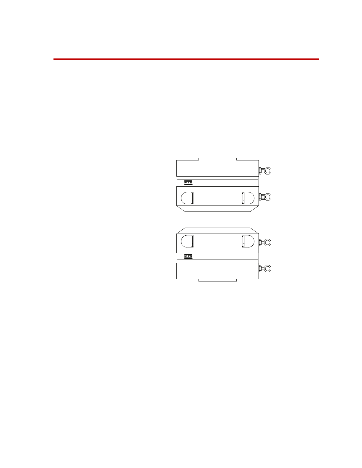
Model 646.10
Model 646.25
011-558-204 H
Page 2

Copyright information © 1991, 2001, 2004, 2008, 2009 MTS Systems Corporation. All rights reserved.
Trademark information MTS is a registered trademark of MTS Systems Corporation within the United
States. This trademark may be protected in other countries.
Molykote is a registered trademark of Dow Chemical Corporation. All other
trademarks or service marks are property of their respective owners.
Publication information
MANUAL PART NUMBER PUBLICATION DATE
011-558-204 B May 1991
011-558-204 C February 2001
011-558-204 D June 2001
011-558-204 E April 2004
011-558-204 F March 2008
011-558-204 G April 2009
011-558-204 H August 2012
2
Manual Template 4.3
Page 3

Contents
Technical Support 5
How to Get Technical Support 5
Before You Contact MTS 5
If You Contact MTS by Phone 7
Problem Submittal Form in MTS Manuals 8
Preface 9
Before You Begin 9
Conventions 10
Documentation Conventions 10
Introduction 13
Series 646 Hydraulic Collet Grips Component Identification 14
About Series 646 Hydraulic Collet Grips 16
About Gripping Specimens 16
Collet Sets 16
Spiral Washers 16
Couplings 17
Specifications 18
Series 646 Hydraulic Collet Grips Dimensions 18
Model 646 Grip with Furnace Extensions Dimensions 19
Series 646 Hydraulic Collet Grips Force and Torque Capacities 20
Series 646 Hydraulic Collet Grips Specifications—Round Specimens 22
Series 646 Hydraulic Collet Grips Specifications—Flat Specimens 23
Series 646 Hydraulic Collet Grips Specifications—Threaded Specimens 24
Safety Information 25
General Safety Practices: Grips and Fixtures 25
General Precautions for Environmental Components 30
Hazard Placard Placement 30
Series 646 Hydraulic Collet Grips Contents
3
Page 4

Installation 33
646 Hydraulic Grip Lift Points 33
About Axial Grip Installation 34
Axial Grip Installation Procedure 36
About Axial-Torsional Grip Installation 40
Axial Torsional Grip Installation Procedure 41
Grip Alignment 45
How to Preload the Spiral Washers 45
Grip Water Cooling Assembly Configurations for Servohydraulic Frames 48
Operation 51
Determine the Gripping Pressure 52
Grip Alignment Markings 54
Installing a Collet for a Round Specimen 55
Installing a Collet for a Flat Specimen 56
Installing a Collet for a Threaded Specimen 57
Installing a Round or Flat Specimen 59
Installing a Threaded Specimen 60
Adjust Water Cooling Flow 62
Removing Specimen 63
Maintenance 65
Hydraulic Hoses and Fittings 65
Collets 65
Water Cooling Components 65
Daily Inspections 65
4
Contents
Series 646 Hydraulic Collet Grips
Page 5

Technical Support
How to Get Technical Support
Start with your
manuals
Technical support
methods
The manuals supplied by MTS provide most of the information you need to use
and maintain your equipment. If your equipment includes software, look for
online help and README files that contain additional product inform ation.
If you cannot find answers to your technical questions from these sources, you
can use the Internet, e-mail, telephone, or fax to contact MTS for assistance.
MTS provides a full range of support services after your system is installed. If
you have any questions about a system or product, contact Technical Support in
one of the following ways.
www.mts.com The web site provides access to our technical support staff by means of an
onlineform:
www.mts.com > Contact MTS > Service & Technical Support button
E-mail tech.support@mts.com
Telephone MTS Call Center 800-328-2255
Weekdays 7:00 A.M. to 5:00 P.M., Central Time
Fax 952-937-4515
Please include “Technical Support” in the subject line.
Outside the U.S. For technical support outside the United States, contact your local sales and
service office. For a list of worldwide sales and service locations and contact
information, use the Global MTS link at the MTS web site:
www.mts.com > Global MTS > (choose your region in the right-hand
column) > (choose the location closest to you)
Before You Contact MTS
MTS can help you more efficiently if you have the following information
available when you contact us for support.
Know your site
number and system
number
Series 646 Hydraulic Collet Grips Technical Support
The site number contains your company number and identifies your equipment
type (such as material testing or simulation). The number is typically written on a
label on your equipment before the system leaves MTS. If you do not know your
MTS site number, contact your sales engineer.
Example site number: 571167
When you have more than one MTS system, the system job number identifies
your system. You can find your job number in your order paperwork.
Example system number: US1.42460
5
Page 6

Know information from
prior technical
If you have contacted MTS about this problem before, we can recall your file
based on the:
assistance
• MTS notification number
• Name of the person who helped you
Identify the problem Describe the problem and know the answers to the following questions:
• How long and how often has the problem occurred?
• Can you reproduce the problem?
• Were any hardware or software changes made to the system before the
problem started?
• What are the equipment model numbers?
• What is the controller model (if applicable)?
• What is the system configuration?
Know relevant
computer information
Know relevant
software information
For a computer problem, have the following information available:
• Manufacturer’s name and model number
• Operating software type and service patch information
• Amount of system memory
• Amount of free space on the hard drive where the application resides
• Current status of hard-drive fragmentation
• Connection status to a corporate network
For software application problems, have the following information available:
• The software application’s name, version number, build number, and (if
available) software patch number. This information can typically be found
in the About selection in the Help menu.
• The names of other applications on your computer, such as:
– Anti-virus software
– Screen savers
– Keyboard enhancers
– Print spoolers
Technical Support
6
– Messaging applications
Series 646 Hydraulic Collet Grips
Page 7

If You Contact MTS by Phone
A Call Center agent registers your call before connecting you with a technical
support specialist. The agent asks you for your:
• Site number
• Name
• Company name
• Company address
• Phone number where you can be reached
If your issue has a notification number, please provide that number. A new issue
will be assigned a unique notification number.
Identify system type To enable the Call Center agent to connect you with the most qualified technical
support specialist available, identify your system as one of the following types:
• Electromechanical material test system
• Hydromechanical material test system
• Vehicle test system
• Vehicle component test system
Be prepared to
troubleshoot
Write down relevant
information
After you call MTS logs and tracks all calls to ensure that you receive assistance for your
• Aero test system
Prepare to perform troubleshooting while on the phone:
• Call from a telephone close to the system so that you can implement
suggestions made over the phone.
• Have the original operating and application software media available.
• If you are not familiar with all aspects of the equipment operation, have an
experienced user nearby to assist you.
In case Technical Support must call you:
• Verify the notification number.
• Record the name of the person who helped you.
• Write down any specific instructions.
problem or request. If you have questions about the status of your problem or
have additional information to report, please contact Technical Support again and
provide your original notification number.
Series 646 Hydraulic Collet Grips Technical Support
7
Page 8

Problem Submittal Form in MTS Manuals
Use the Problem Submittal Form to communicate problems with your software,
hardware, manuals, or service that are not resolved to your satisfaction through
the technical support process. The form includes check boxes that allow you to
indicate the urgency of your problem and your expectation of an acceptable
response time. We guarantee a timely response—your feedback is important to
us.
Access the Problem Submittal Form:
• In the back of many MTS manuals (postage paid form to be mailed to MTS)
• www.mts.com > Contact Us > Problem Submittal Form button (electronic
form to be e-mailed to MTS)
Technical Support
8
Series 646 Hydraulic Collet Grips
Page 9

Preface
Before You Begin
Safety first! Before you use your MTS product or system, read and understand the Safety
manual and any other safety information provided with your system. Improper
installation, operation, or maintenance can result in hazardous conditions that can
cause severe personal injury or death, or damage to your equipment and
specimen. Again, read and understand the safety information provided with your
system before you continue. It is very important that you remain aware of
hazards that apply to your system.
Other MTS manuals In addition to this manual, you may receive additional manuals in paper or
electronic form.
You may also receive an MTS System Documentation CD. It contains an
electronic copy of the manuals that pertain to your test system, such as:
• Hydraulic and mechanical component manuals
• Assembly drawings
• Parts lists
• Operation manual
• Preventive maintenance manual
Controller and application software manuals are typically included on the
software CD distribution disc(s).
Series 646 Hydraulic Collet Grips Preface
9
Page 10

Conventions
DANGER
WARNING
CAUTION
Conventions
Documentation Conventions
The following paragraphs describe some of the conventions that are used in your
MTS manuals.
Hazard conventions Hazard notices may be embedded in this manual. These notices contain safety
information that is specific to the activity to be performed. Hazard notices
immediately precede the step or procedure that may lead to an associated hazard.
Read all hazard notices carefully and follow all directions and recommendations.
Three different levels of hazard notices may appear in your manuals. Following
are examples of all three levels.
Note For general safety information, see the safety information provided with
your system.
Danger notices indicate the presence of a hazard with a high level of risk which,
if ignored, will result in death, severe personal injury, or substantial property
damage.
Warning notices indicate the presence of a hazard with a medium level of risk
which, if ignored, can result in death, severe personal injury, or substantial
property damage.
Caution notices indicate the presence of a hazard with a low level of risk which,
if ignored, could cause moderate or minor personal injury or equipment damage,
or could endanger test integrity.
Notes Notes provide additional information about operating your system or highlight
easily overlooked items. For example:
Note Resources that are put back on the hardware lists show up at the end of
the list.
Special terms The first occurrence of special terms is shown in italics.
Illustrations Illustrations appear in this manual to clarify text. They are examples only and do
not necessarily represent your actual system configuration, test application, or
software.
Electronic manual
conventions
This manual is available as an electronic document in the Portable Document
File (PDF) format. It can be viewed on any computer that has Adobe Acrobat
Reader installed.
10
Preface
Series 646 Hydraulic Collet Grips
Page 11

Conventions
Hypertext links The electronic document has many hypertext links displayed in a blue font. All
blue words in the body text, along with all contents entries and index page
numbers, are hypertext links. When you click a hypertext link, the application
jumps to the corresponding topic.
Series 646 Hydraulic Collet Grips Preface
11
Page 12

Conventions
12
Preface
Series 646 Hydraulic Collet Grips
Page 13
Introduction
646 Hydraulic Collet Grip
646 Hydraulic Collet Grip
Contents Series 646 Hydraulic Collet Grips Compon ent Identification 14
MTS Series 646 Hydraulic Collet Grips grasp and hold a specimen in place
during testing, and provide a constant, hydraulically actuated gripping force
regardless of the applied test loads. They are designed to perform in a wide
variety of testing applications including high and low cycle fatigue, tension, and
compression testing.
About Series 646 Hydraulic Collet Grips 16
Specifications 18
Series 646 Hydraulic Collet Grips Introduction
Series 646 Hydraulic Collet Grips
What you need to
know
This manual assumes that you know how to use your system controller. See the
appropriate manual for information about performing any controller-related step
in this manual’s procedures. You are expected to know how to do the following:
• Turn hydraulic pressure on and off.
• Select a control mode.
• Manually adjust the actuator position.
• Monitor a sensor signal.
• Zero a sensor output.
Related products The grips are usually controlled with a dedicated hydraulic supply. See the Series
685 Hydraulic Grip Supply Product Information manual (MTS part number 015-
205-001).
13
Page 14

Actuator
Rod
Load Unit
Base Plate
Shim
Spiral
Washers
Threaded
Mounting Stud
Lower Grip
Hydraulic Pressure
and Return Ports
Collets
Lower
Coupling
Upper Grip
Threaded
Mounting
Stud
Spiral
Washers
Shim
Upper
Coupling
Adapter
Plate
Force Transduc er
(attached to the load
unit crosshead)
Axial Grip Mounting
Axial/T o rsio nal Grip Moun tin g
Series 646 Hydraulic Collet Grips Component Identification
Introduction
14
Series 646 Hydraulic Collet Grips
Page 15

Hydraulic Grip Components
TEM DESCRIPTION
I
Load unit crosshead and
base plate
Force transducer
Hydraulic pressure
and return lines
Upper and lower grips
Collet
Actuator rod
Provides the structure to mount the grips and other components in the force
train. It is also the reaction mass for the force train. The crosshead and base
plate are connected with columns.
Measures the axial forces applied to the specimen. An axial-torsional version
also measures the rotational forces applied to the specimen.
The force transducer can be located in the base or the crosshead of the load
unit.
Ports the hydraulic fluid to and from the grips. The hydraulic fluid comes from
a dedicated hydraulic grip supply that produces 45 MPa (6500 psi). Each grip
has two hydraulic lines connected to it, a hydraulic pressure line and a
hydraulic return line.
Clamps a specimen in place. The grips house the collets and the hydraulic
components that operate the grips.
Contacts and holds the specimen in place. Collets are available for flat, round,
and threaded specimens.
Applies axial forces to a specimen. The actuator is a hydraulically powered
device that provides linear displacement of (or forces into) a specimen. For
axial-torsional systems, the actuator applies both axial and torsional forces to
the specimen.
The actuator rod can be located in the base or the crosshead of the load unit.
Axial attachment kit
Shims
Spiral washers
Mounting stud
Adapter plate
Upper and lower
couplings
Includes the required components to install the grips. Each grip model/load
unit model combination has a unique attachment kit.
Allows further rotation of the grips to change the orientation of the spiral
washers so the appropriate opening is set. When axial grips are installed, the
upper and lower grips might not be aligned after being screwed onto the
mounting studs. Shims can be added so that the amount of rotation can be
changed. The shims are available in thicknesses that correspond with 1/8 to 1/2
turns of rotation.
Ensures preloading without inducing offsets in the force train. They provide a
backlash-free union of threaded components.
Mounts the grips to the other components in the force train. Connector studs
are threaded rods that connect the grips with an actuator rod or force
transducer.
Allows axial-torsional grips to be mounted to a force transducer. The adapter
provides the thread needed to use the couplings.
Clamps the grips to the to the actuator and force transducer. The couplings
have left and right handed threads that preload the grip connection and
prevents backlash in the force train.
Series 646 Hydraulic Collet Grips Introduction
15
Page 16

About Series 646 Hydraulic Collet Grips
Preload Chamber
Grip Piston
Grip Housing
Collet
Hydraulic
Release
Port
Hydraulic
Pressure
Port
The Series 646 Hydraulic Collet Grips are mounted in a load unit to secure the
specimen under test. Hydraulic pressure to the grips is supplied by an external
hydraulic grip supply.
Grip Cross Section
About Gripping Specimens
The grips provide a constant, hydraulically actuated gripping force regardless of
the applied test loads. When hydraulic pressure is applied, it pulls the grip
housing towards the piston, forcing the collet to clamp the specimen. The
pressure applied to the preload chamber locks all moving grip parts in position.
This eliminates backlash when cycling between tension and compression.
The specimen gripping force is adjustable to prevent specimen damage by the
grips or specimen slippage during the test. Each grip (upper and lower) is
independently actuated.
Collet Sets
The grips require collet inserts to accommodate the type of specimen. Various
specimen geometries may be easily accommodated by changing only the collet
sets. Three types of collets are available; round, flat, and threaded.
Spiral Washers
The optional Model 601 Spiral Washers are commonly used when installing axial
grips. They provide fatigue-resistant connections between elements of the force
train and minimize the effects of backlash.
16
Introduction
The spiral washers are placed over the connector studs and adjusted to place a
constant preload on the stud. The spiral washers also minimize the possibility of
backlash due to loose-fitting or worn stud threads. When cyclic loads below the
tensile force level of the preload are applied to the connections, the load is
Series 646 Hydraulic Collet Grips
Page 17

Couplings
distributed between the surfaces of the spiral washers and the stud in a ratio of
the relative stiffness of the parts. The spiral washers have a large surface area and
therefore greater stiffness. They react to most of the load and keep the stress in
the stud below its fatigue runout level.
Special upper and lower couplings clamp the grips to the actuator and force
transducer for axial-torsional grips. Each coupling has two different thread
patterns; a right hand thread with a pitch of 3 mm and a left hand thread with a 2
mm pitch. Half of the coupling matches the thread of the grip and the other half
matches the thread of the actuator or force transducer adapter. Each coupling is
marked to indicate which direction to tighten it and how much torque to lock it
down.
Series 646 Hydraulic Collet Grips Introduction
17
Page 18

Specifications
Specifications
Contents Series 646 Hydraulic Collet Grips Dimensions 18
Series 646 Hydraulic Collet Grips Force and Torque Capacities 20
Series 646 Hydraulic Collet Grips Specifications—Round Specimens 22
Series 646 Hydraulic Collet Grips Specifications—Flat Specimens 23
Series 646 Hydraulic Collet Grips S pecifications—Thread ed Specimens
24
Series 646 Hydraulic Collet Grips Dimensions
The following sections provide the dimensions of the Series 646 Hydraulic Collet
Grips.
Series 646 Collet Grip Dimensions
M
ODEL ABCCONNECTOR STUD
646.10 Axial 107.4 mm
(4.23 in)
646.25 Axial 171.7 mm
(6.76 in)
646.10 Axial/Torsional 107.4 mm
(4.23 in)
646.25 Axial/Torsional 171.7 mm
(6.76 in)
* Left Handed Threads
Introduction
18
171.5 mm
(6.75 in)
254 mm
(10.0 in)
171.5 mm
(6.75 in)
254 mm
(10.0 in)
–7.2 mm
4.0
(0.16
4.6
–9.4 mm
(0.18
36.5
(1.44
54.1
(2.13
–0.28 in)
–0.37 in)
–39.6 mm
–1.56 in)
–58.9 mm
–2.32 in)
Series 646 Hydraulic Collet Grips
M27 x 2
(1-14)
36 x 2
(1 1/2-12)
M68 x 2
M92 x 3
-
*
*
Page 19
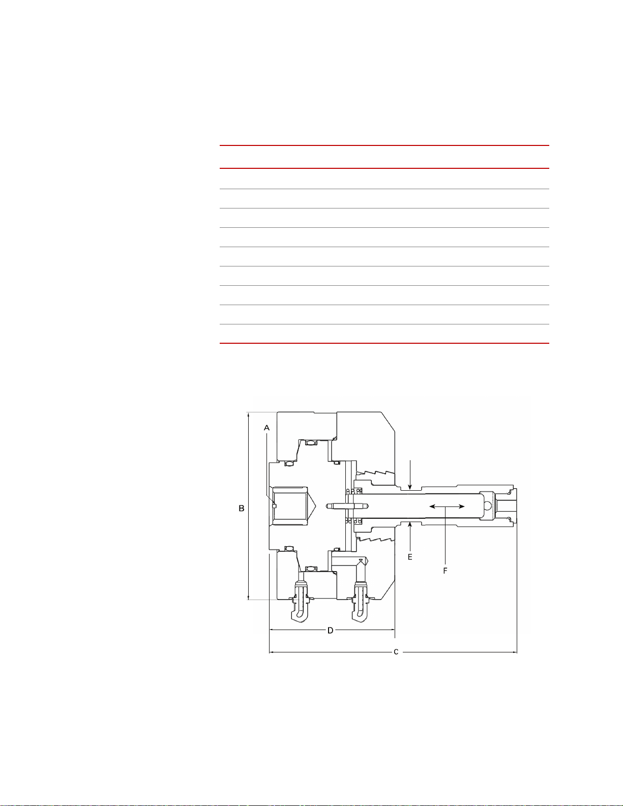
Model 646 Grip with Furnace Extensions Dimensions
Mounting holes in the base of each grip are threaded in either SI International
(millimeter) or U.S. Customary (inch) thread dimensions, as shown for
dimension “A” in the pervious table.
Specifications
ARAMETER
P
A (mounting threads)
B 172 mm (6.77 in)
C 224 mm (8.80 in)
D 115 mm (4.52 in)
E (wrench flats) 29 mm (1.125 in)
F (travel) 3.2 mm (0.125 in)
G (specimen adapter wrench flats) 32 mm (1.25 in)
H (maximum diameter) 38 mm (1.5 in)
Weight (each grip) 18.5 kg (40.8 lb)
* SI International (U.S. Customary)
DIMENSION
M27 x 2mm or 1 in
*
–14
Series 646 Hydraulic Collet Grips Introduction
19
Page 20

Specifications
Torque (in-lbs)
0
1000
2000
3000
4000
5000
6000
7000
8000
9000
10000
6 mm dia
.25" dia
.375 " dia
.5" dia
15 mm dia
.75" dia
20 mm dia
1" dia
30 mm dia
4000
6000
2000
8000
10000
12000
14000
16000
18000
20000
22000
Force (lbs)
Specimen
Diameter
Series 646 Hydraulic Collet Grips Force and Torque Capacities
The amount of torque the grips can produce is reduced with biaxial operation.
The amount of torque is affected by the amount of axial force and the size of the
specimen. The following graphs illustrate the axial-torsional perfor mance
envelope of the Model 646.10 and Model 646.25 Hydraulic Collet Grips.
Series 646 Collet Grip Specifications
M
ODEL
AXIAL CAPACITY
*
TORSIONAL CAPACITY
646.10 Axial 100 kN (22 kip) – 18 kg (40 lb)
646.25 Axial 250 kN (55 kip) – 72 kg (160 lb)
*
WEIGHT
646.10 Axial/Torsional 100 kN (22 kip)
646.25 Axial/Torsional 250 kN (55 kip)
* Ratings are at 45 MPa (6500 psi).
1100 N
·m (10,000 lbf·in)
2200 N
·m (20,000 lbf·in)
18 kg (40 lb)
72 kg (160 lb)
20
Introduction
Model 646.10 Maximum Torque versus Axial Load
Series 646 Hydraulic Collet Grips
Page 21

Specifications
Torque (in-lbs)
0
5000
10000
15000
20000
.25 " dia
.375" dia
.5" dia
.75" dia
20 mm dia
4000
6000
2000
8000
10000
12000
14000
16000
18000
20000
22000
Force (lbs)
Specimen
Diameter
Model 646.25 Maximum Torque versus Axial Load
Note The Series 646.25 Axial-Torsional Grips are capable of holding full
torque and full load with specimen sizes greater than 24.6 mm (0.97 in).
Series 646 Hydraulic Collet Grips Introduction
21
Page 22

Specifications
Top View
Collet
Assembly
Collet Retainer
Socket Head Cap
Screw
Cutaway
Side View
Coat Threads on
Collet with Molykote
G-n Paste
Series 646 Hydraulic Collet Grips Specifications—Round Specimens
SI M
ETRIC U.S. CUSTOMARY
MODEL
D* X L
646.10 8 x 30 mm 038-058-904 0.25 x 1.2 in. 038-058-905
646.10 12 x 30 mm 038-058-903 0.375 x 1.2 in. 038-058-906
646.10 15 x 30 mm 038-058-902 0.5 x 1.2 in. 038-058-907
646.10 30 x 30 mm 038-058-901 1.0 x 1.2 in. 038-058-908
646.25 20 x 58 mm 038-059-203 0.5 x 2.3 in. 038-059-205
646.25 30 x 58 mm 038-059-204 0.75 x 2.3 in. 038-059-201
646.25 - - 1.0 x 2.3 in. 038-059-202
* The tolerance for the diameter (D) is ±0.025 mm (±0.001 in).
PART NUMBER
D* X L
P
ART NUMBER
22
Introduction
Series 646 Hydraulic Collet Grips
Page 23

Specifications
Rubber Platen
Collet
Assembly
Alignment
Mark
Top View
Cutaway Side
View
Coat Threads on
Collet with
Molykote G-n
Flat Specimen
Series 646 Hydraulic Collet Grips Specifications—Flat Specimens
SI M
ETRIC U.S. CUSTOMARY
MODEL
T X W X L
646.10 1.5 x 6.0 x 25 mm 038-059-104 0.0625 x 0.25 x 1.0 in 038-059-101
646.10 3.0 x 12 x 25 mm 038-059-105 0.125 x 0.5 x 1.0 in 038-059-102
646.10 6.0 x 24 x 25 mm 038-059-106 0.25 x 1.0 x 1.0 in 038-059-103
646.25 - - 0.25 x 1.0 x 2.2 in 038-059-301
646.25 - - 0.375 x 1.5 x 2.2 in 038-059-302
646.25 - - 0.5 x 2.0 x 2.2 in 038-059-303
646.25 - - 0.625 x 2.5 x 2.2 in 038-059-304
* The tolerance for width (W) is ±0.254 mm (±0.01 in); the tolerance for thickness (T) is +0.000, -0.051 mm
(+0.000, -0.002 in).
*
PART NUMBER
T X W X L
*
PART NUMBER
Series 646 Hydraulic Collet Grips Introduction
23
Page 24

Specifications
Threaded Specimen
Retainer Screw
Thread
Preload Platen
Alignment Mark
Coat Threads
with Molykote
G-n Paste
Threaded Insert
Spanner
Wrench
Holes (4)
Collet
Retainer
Top View
Cutaway
Side View
Series 646 Hydraulic Collet Grips Specifications—Threaded Specimens
SI M
ETRIC U.S. CUSTOMARY
MODEL
646.10 M6 x 1 mm 11 mm 038-059-004 1/4-20 UNC-2A 0.44 in 038-059-001
646.10 M10 x 1.5 mm 16 mm 038-059-005 3/8-16 UNC-2A 0.62 in 038-059-002
646.10 M16 x 2 mm 25 mm 038-059-006 1/2-13 UNC-2A 0.81 in 038-059-003
* The tolerance for the length (L) is ±0.762 mm (±0.03 in).
THREAD
*
L
PART NUMBER THREAD
*
L
PART NUMBER
24
Introduction
Series 646 Hydraulic Collet Grips
Page 25

Safety Information
General Safety Practices: Grips and Fixtures
Typically, grips and fixtures are part of equipment used in MTS testing systems.
This section provides general information about safety issues that pertain to
systems that use grips and fixtures. These issues include statements to the
intended use and foreseeable misuse of the system and definition for the
graphical hazard labeling that is affixed to your product, and other (more general)
safety information that relates to the high-pressure and high-performance
characteristics of MTS servohydraulic and electromechanical systems.
When you prepare to operate a system that includes grips or fixtures, ensure the
following:
• Do not use or allow personnel to operate the system who are not
experienced, trained, or educated in the inherent dangers associated with
high-performance servo hydraulics and who are not experienced, trained, or
educated with regard to the intended operation as it applies to this test
system.
• Do not disable safety components or features (including limit detectors,
light curtains, or proximity switches/detectors).
• Do not attempt to operate the system without appropriate personal safety
gear (for example, hearing, hand, and eye protection).
• Do not modify the system or replace system components using parts that are
not MTS component parts or effect repairs using parts or components that
are not manufactured to MTS specifications.
• Do not operate the grips or fixtures in an explosive atmosphere.
• Do not use the system in a test area where uncontrolled access to the test
system is allowed when the system is in operation.
• For servohydraulic systems, do not operate the system unless an interlock is
installed to monitor supply pressure into the HSM and initiate a system
interlock if a low or no pressure event occurs.
If you have system related responsibilities (that is, if you are an operator, service
engineer, or maintenance person), you should study safety information carefully
before you attempt to perform any test system procedure.
You should receive training on this system or a similar system to ensure a
thorough knowledge of your equipment and the safety issues that are associated
with its use. In addition, you should gain an understanding of system functions
by studying the other manuals supplied with your test system. Contact MTS for
information about the content and dates of training classes that are offered.
It is very important that you study the following safety information to ensure that
your facility procedures and the system’s operating environment do not
contribute to or result in a hazardous situation. Remember, you cannot eliminate
all the hazards associated with this system, so you must learn and remain aware
Series 646 Hydraulic Collet Grips Safety Information
25
Page 26

of the hazards that apply to your system at all times. Use these safety guidelines
WARNING
to help learn and identify hazards so that you can establish appropriate training
and operating procedures and acquire appropriate safety equipment (such as
gloves, goggles, and hearing protection).
Each test system operates within a unique environment which includes the
following known variables:
• Facility variables (facility variables include the structure, atmosphere, and
utilities)
• Unauthorized customer modifications to the equipment
• Operator experience and specialization
• Test specimens
Because of these variables (and the possibility of others), your system can
operate under unforeseen circumstances that can result in an operating
environment with unknown hazards.
Improper installation, operation, or maintenance of your system can result in
hazardous conditions that can cause death, personal injury, or damage to the
equipment or to the specimen. Common sense and a thorough knowledge of the
system’s operating capabilities can help to determine an appropriate and safe
approach to its operation.
The larger capacity grips are heavy.
Dropped grips can cause injury to personnel and damage to equipment.
Be sure to have help or proper lifting devise to position the grips for installation.
Read all manuals Study the contents of this manual and the other manuals provided with your
system before attempting to perform any system function for the first time.
Procedures that seem relatively simple or intuitively obvious may require a
complete understanding of system operation to avoid unsafe or dangerous
situations.
Avoid pinch/crush
points
Pinch points exist between the parts of the grip or fixture that contact the
specimen. Be aware of these pinch points when installing a specimen or working
around the grip or fixture during test setup. High forces generated when grip
pressure is activated can pinch, cut, or crush anything in the path of the grip/
fixture specimen contact area and cause serious injury . Stay clear of any potential
pinch points.
A crush point exists between the grips. Whenever possible, use tongs or similar
tool when handling the specimen during specimen installation. Never allow any
part of your body to enter the path of machine movement or to touch moving
machinery , linkages, hoses, cables, specimens, and so forth. These present
serious crush points or pinch points.
Safety Information
26
Series 646 Hydraulic Collet Grips
Page 27

Locate and read
hazard placards/labels
Find, read, and follow the hazard placard instructions located on the equipment.
These placards are placed strategically on the equipment to call attention to areas
such as known crush points, electrical voltage, and high pressure hazards.
Know facility safe
procedures
Most facilities have internal procedures and rules regarding safe practices within
the facility. Be aware of these safe practices and incorporate them into your daily
operation of the system.
Know controls Before you operate the system for the first time, make a trial run through the
operating procedures with the power off. Locate all hardware and software
controls and know what their functions are and what adjustments they require. If
any control function or operating adjustment is not clear, review the applicable
information until you understand it thoroughly.
Know specimen
properties
The user is responsible for understanding the characteristics of the test specimen.
Be sure to use appropriate personal protective equipment (clothing, hand gloves,
eye protection etc.).
Use protective guards such as cages, enclosures, and special laboratory layouts
when you work with hazardous test specimens (for example, brittle or
fragmenting materials or materials that are internally pressurized).
Have first aid available Accidents can happen even when you are careful. Arrange your operator
schedules so that a properly trained person is always close by to render first aid.
In addition, ensure that local emergency contact information is posted clearly and
in sight of the system operator.
Be aware of
component movement
with hydraulics off
The actuator rod can also drift down when hydraulics are turned off hitting
anything in its path. This uncommanded movement is because of oil movement
between the pressure/return ports and oil blow by across the piston hub. Be aware
that this can happen and clear the area around the actuator rod when hydraulics
are turned off.
Keep bystanders
safely away
Keep bystanders at a safe distance from all equipment. Never allow bystanders to
touch specimens or equipment while the test is running.
Wear proper clothing Do not wear neckties, shop aprons, loose clothing or jewelry, or long hair that
could get caught in equipment and result in an injury. Remove loose clothing or
jewelry and restrain long hair.
Series 646 Hydraulic Collet Grips Safety Information
27
Page 28

Remove flammable
WARNING
fluids
Remove flammable fluids from their containers or from components before you
install the container or component. If desired, you can replace the flammable
fluid with a non-flammable fluid to maintain the proper proportion of weight and
balance.
Check bolt ratings and
torques
To ensure a reliable product, fasteners (such as bolts and tie rods) used in MTSmanufactured systems are torqued to specific requirements. If a fastener is
loosened or the configuration of a component within the system is modified, refer
to information in this product manual to determine the correct fastener, fastener
rating, and torque. Overtorquing or undertorquing a fastener can create a
hazardous situation due to the high forces and pressures present in MTS test
systems.
On rare occasions, a fastener can fail even when it is correctly installed. Failure
usually occurs during torquing, but it can occur several days later. Failure of a
fastener can result in a high velocity projectile. Therefore, it is a good practice to
avoid stationing personnel in line with or below assemblies that co ntai n large or
long fasteners.
Lift equipment safely Grips that are too heavy to be lifted by hand are to be lifted with double swivel
eyebolts supplied by MTS, part number 100-263-718.
Large capacity grips are heavy, and must be lifted using hoist rings.
Such grips should be lifted with hoist rings supplied by MTS Systems
Corporation.
Practice good
housekeeping
Do not exceed the
Maximum Supply
Pressure
Do not disable safety
devices
Provide adequate
lighting
Provide means to
access out-of-reach
components
If hoist rings other than those provided by MTS are used, the customer must
ensure that the other grips are suitable for the purpose.
Keep the floors in the work area clean. Hydraulic fluid that is spilled on any type
of floor can result in a dangerous, slippery surface. Do not leave tools, fixtures,
or other items not specific to the test, lying about on the floor, system, or decking.
For hydraulic grips and fixtures. make sure that the hydraulic supply pressure is
limited to the maximum pressure defined by the grip or fixture identification (ID)
tag.
Your system may have active or passive safety devices installed to prevent
system operation if the device indicates an unsafe condition. Do not disable such
devices as it may result in unexpected system motion.
Ensure adequate lighting to minimize the chance of operation errors, equipment
damage, and personal injury. You need to see what you are doing.
Make sure you can access system components that might be out of reach while
standing on the floor. For example, ladders or scaffolding might be required to
reach load cell connectors on tall load units.
Safety Information
28
Series 646 Hydraulic Collet Grips
Page 29

Wear appropriate
personal protection
Wear eye protection when you work with high-pressure hydraulic fluid,
breakable specimens, or when anything characteristic to the specimen could
break apart.
W ear ear protection when you work near electric motors, pumps, or other devices
that generate high noise levels. Some systems can create sound pressure levels
that exceed 70 dbA during operation.
W ear appropriate personal protection equipment (gloves, boots, suits, respirators)
whenever you work with fluids, chemicals, or powders that can irritate or harm
the skin, respiratory system, or eyes.
Handle chemicals
safely
Know system
interlocks
Whenever you use or handle chemicals (for example, cleaning fluids, hydraulic
fluid, batteries, contaminated parts, electrical fluids, and maintenance waste),
refer to the appropriate MSDS documentation for that material and determine the
appropriate measures and equipment required to handle and use the chemical
safely. Ensure that the chemical is disposed of appropriately.
Interlock devices should always be used and properly adjusted. Interlock devices
are designed to minimize the chance of accidental damage to the test specimen or
the equipment. Test all interlock devices for proper operation immediately before
a test. Do not disable or bypass any interlock devices as doing so could allow
hydraulic pressure to be applied regardless of the true interlock condition. The
Reset/Override button is a software function that can be used to temporarily
override an interlock while attempting to gain control of the system.
Know system limits Never rely on system limits such as mechanical limits or software limits to
protect you or any personnel. System limits are designed to minimize the chance
of accidental damage to test specimens or to equipment. T est all limits for proper
operation immediately before a test. Always use these limits and adjust them
properly.
Do not disturb sensors Do not bump, wiggle, adjust, disconnect, or otherwise disturb a sensor (such as
an accelerometer or extensometer) or its connecting cable when hydraulic
pressure is applied.
Ensure secure cables Do not change any cable connections when electrical power or hydraulic pressure
is applied. If you attempt to change a cable connection while the system is in
operation, an open control loop condition can result. An open control loop
condition can cause a rapid, unexpected system response which can result in
severe personal injury, death, or damage to equipment. Also, ensure that all
cables are connected after you make any changes in the system configuration.
Stay alert A void long periods of work without adequate rest. In addition, avoid long periods
of repetitious, unvarying, or monotonous work because these conditions can
contribute to accidents and hazardous situations. If you are too familiar with the
work environment, it is easy to overlook potential hazards that exist in that
environment.
Contain small leaks Do not use your fingers or hands to stop small leaks in hydraulic or pneumatic
hoses. Substantial pressures can build up, especially if the hole is small. These
high pressures can cause the oil or gas to penetrate your skin, causing painful and
dangerously infected wounds. Turn off the hydraulic supply and allow the
Series 646 Hydraulic Collet Grips Safety Information
29
Page 30

hydraulic pressure to dissipate before you remove and replace the hose or any
pressurized component.
Stay clear of moving
equipment/avoid crush
points
Know the causes of
unexpected actuator
motions
Stay clear of mechanical linkages, connecting cables, and hoses that move
because you can get pinched, crushed, tangled, or dragged along with the
equipment. High forces generated by the system can pinch, cut, or crush anything
in the path of the equipment and cause serious injury. Stay clear of any potential
crush points. Most test systems can produce sudden, high-force motion. Never
assume that your reactions are fast enough to allow you to escape injury when a
system fails.
The high force and velocity capabilities of MTS actuators can be destructive and
dangerous (especially if actuator motion is unexpected). The most likely causes
of unexpected actuator response are operator error and equipment failure due to
damage or abuse (such as broken, cut, or crushed cables and hoses; shorted wires;
overstressed feedback devices; and damaged components within the servocontrol
loop). Eliminate any condition that could cause unexpected actuator motion.
General Precautions for Environmental Components
Observe the following precautions when operating the grips:
• Make sure controller detectors are set to minimize the chance of the grip
contacting the furnace. Generally this involves setting displacement limits
to restrict actuator rod travel.
• When positioning the crosshead during specimen installation, be careful not
to allow contact of machine components with the environmental chamber or
furnace. Machine components can include grips, attachment kits, the
crosshead, pullrods, etc.
• Be sure to read and understand the safety data sheets of the materials,
• After operation at elevated temperature, be sure to allow components to cool
• Use protective gear (such as gloves) if it is necessary to handle hot objects.
• When using an environmental chamber or furnace, be aware of possible
Hazard Placard Placement
Hazard placards contain specific safety information and are affixed directly to the
system so they are plainly visible.
Each placard describes a system-related hazard. When possible, international
symbols (icons) are used to graphically indicate the type of hazard and the
placard label indicates its severity. In some instances, the placard may contain
chemicals, and fluids used regarding any combustibility and toxicity
characteristics.
before handling. Components can include grips, specimen, environmental
chamber or furnace surfaces.
Hot objects can include specimens tested at elevated temperatures or
furnace surfaces.
crush points between the grip and any attachment fixture and the chamber or
furnace.
Safety Information
30
Series 646 Hydraulic Collet Grips
Page 31

text that describes the hazard, the potential result if the hazard is ignored, and
general instructions about how to avoid the hazard.
The following label is typically located on the grip.
ABEL DESCRIPTION
L
646 Hydraulic Collet Grip
Force Capacity: 100 kN / 22 kip
Max Operating Pressure: 45 MPa / 6,500 psi
Model No.
Part No.
MTS Systems Corporation
14000 Technology Drive
Eden Prairie MN U.S.A. 55344-2247
Part # 513251-01
Grip ID label. Contains the following information:
• Force capacity
• Maximum operating pressure
• Model number
• Part number
• Serial number
• Revision
Serial No.
Rev. Level
Grip
PN 5213251-01
Series 646 Hydraulic Collet Grips Safety Information
31
Page 32

Safety Information
32
Series 646 Hydraulic Collet Grips
Page 33

Installation
WARNING
Two holes
180° apart
Contents About Axial Grip Installation 34
This section describes how to install and align the Series 646 Hydraulic Collet
Grips.
Axial Grip Installation Procedure 36
About Axial-Torsional Grip Installation 40
Axial Torsional Grip Installation Procedure 41
Grip Alignment 45
How to Preload the Spiral Washers 45
Grip Water Cooling Assembly Configurations for Servohydraulic Frames
48
Grip installation is dangerous because it occurs within the crush zone of the
force train while full hydraulic pressure is applied and actuator movement is
required during the installation.
Unexpected actuator movement can cause personal injury and damage to
the equipment.
T ake every precaution to avoid unexpected actuator movement while installing the
grips.
646 Hydraulic Grip Lift Points
MODEL THREAD
646.10 M10 X 1.5 5/8” DP
646.25 M10 X 1.5 5/8” DP
Series 646 Hydraulic Collet Grips Installation
33
Page 34

About Axial Grip Installation
Axial Force Transcucer
Shim
Spiral
Washers
Threaded Mounting Stud
P (Pressure)
R (Return)
Warming/Cooling
Water Ports
R (Return)
P (Pressure)
Threaded Mounting Stud
Spiral W ashers
Shim
Actuator Piston Rod
Load Unit
Base Plate
Installing the grips in a load unit force train involves attaching one grip onto the
end of the actuator rod and one grip to the force transducer. The grips are
mounted to the load unit with connector studs.
The following figure shows the components used for most installations.
Installation Components of the Axial Grips
34
Installation
Series 646 Hydraulic Collet Grips
Page 35

Required equipment Equipment and materials required to install the grips include:
• Molykote G·n paste lubricant.
• Each grip model/load unit combination has a unique attachment kit. The
appropriate attachment kit includes an installation drawing that shows what
components should be installed.
• Adequately sized wood blocks or plywood sheet (or equivalent).
• A lifting device and appropriately sized double swivel eyebolts, as needed.
Series 646 Hydraulic Collet Grips Installation
35
Page 36

Shims If a specific orientation of the grips is required, shims are typically used to
achieve that desired orientation. Use the following table to determine the proper
shims.
Axial Grip Installation Procedure
The following procedure assumes the actuator is mounted in the base of the load
unit and the force transducer is mounted to the crosshead. If you have a load unit
with the actuator mounted to the crosshead, make the appropriate changes to the
following procedure.
Installation
36
Series 646 Hydraulic Collet Grips
Page 37

Note Although it is possible for the grips to be installed by one person, MTS
recommends using two people to lift, handle, and position the grips.
1. Set up the load unit.
A. Turn on the system hydraulic pressure.
B. Adjust the actuator and crosshead position as necessary to allow
adequate room to install the grips.
C. Turn the hydraulic pressure off. Ensure that system hydraulic pressure
has been reduced to zero before proceeding.
D. Clean and lubricate the mounting studs. Clean the mounting studs with
alcohol or similar degreasing solvent. Then lubricate them with
Molykote G·n paste.
E. If needed, install a threaded insert into the actuator rod and the force
transducer.
2. Mount the lower grip to the actuator piston rod using the appropriate
attachment kit.
A. Place a small piece of compliant material (such as styrofoam), to act as
a spacer, inside the connector stud hole of the grip.
B. Thread the mounting stud into the lower grip. The mounting stud
should turn freely. If any resistance is encountered, disassemble and
correct the problem before proceeding.
C. Add any required shims, spacers, or spiral washers to the stud.
Note When installing spiral washers, place them together with the spiral
surfaces facing each other. Rotate the washers until they are fully closed
(minimum thickness).
Series 646 Hydraulic Collet Grips Installation
37
Page 38

D. Position the lower grip to align it with the actuator rod. You might need
WARNING
to stabilize the grip over the actuator.
• Place appropriately sized wood blocks across the load unit base plate,
on opposite sides of the actuator piston rod.
• For heavy grips, insert the double swivel eyebolts into the threaded
holes provided on the grip chamber. Attach a lifting device to the
double swivel eyebolts and carefully raise the grip.
Important NO STANDARD EYEBOLTS should be used to lift the grip.
E. Turn on hydraulic pressure and raise the actuator rod until it just makes
contact with the connector stud. Reposition the grip, as necessary, to
center the stud over the actuator rod.
F. Slowly screw the grip into the actuator rod, raising the actuator rod as
you go, until it is snug.
The connector stud should turn freely. If any resistance is encountered,
disassemble and correct the problem before proceeding.
G. Turn the hydraulic pressure off. Ensure that system hydraulic pressure
has been reduced to zero before proceeding.
3. Mount the upper grip to the force transducer on the crosshead.
Note Ensure that the force transducer is properly aligned with the actuator
(see your load unit manual).
A. Place a small piece of compliant material (such as a piece of
styrofoam), to act as a spacer, inside the connector stud hole of the grip.
B. Thread the mounting stud into the upper grip.
C. Place a wooden spacer (a wood block or piece of plywood) on top of
the lower grip. The wooden spacer should be large enough to cover the
diameter of the grip.
The upper grips are very top heavy and will have a tendency to tip over
when lifted by the double swivel eyebolts.
Dropped grips can cause injury to personnel and damage to equipment.
Never attempt to control the grip by holding onto the double swivel eyebolts. Use
the connector stud to help control the grip balance.
Note You will need help to balance the upper grip on the wooden spacer on
the lower grip. You will need to construct a proper support or have
someone available to help balance the upper grip on the lower grip.
D. Carefully position the grip on top of the wooden spacer on the lower
grip. Ensure that the stud is facing up.
38
Installation
E. Add any required shims, spacer, or spiral washers to the stud.
Series 646 Hydraulic Collet Grips
Page 39

F. Turn on hydraulic pressure and slowly raise the lower grip until the
stud on the upper grip just makes contact with the force transducer.
Reposition the grip, as necessary, for proper thread alignment.
G. Slowly screw the grip into the force transducer until it is snug.
4. Align the grips.
Once the grips are lightly tightened, check the alignment between the upper
and lower grips.
The rotational alignment is critical when you use collets for flat specimens.
Otherwise the rotational alignment is only needed to get the hydraulic
connections in a convenient location and precise alignment is not required.
Align the lower grip as necessary for the desired hydraulic hose
connections. If the actuator rod cannot be rotated, remove the lower grip and
install one or more shim washers or adjust the spiral washers. Reinstall the
grip (go back to Step 2).
Align the upper grip opening with the lower grip. If proper alignment is not
possible, remove the upper grip and install one or more shim washers or
adjust the spiral washers. Reinstall the grip (go back to Step 3).
5. Install the collets.
6. Connect the hydraulics.
Turn the hydraulic pressure off. Ensure that system hydraulic pressure has
been reduced to zero before proceeding.
Using the provided hydraulic hoses, make connections between the pressure
and release ports on the grip and the pressure and release ports on the
external hydraulic grip supply. See your hydraulic grip supply manual for
the port locations.
7. Tighten the grips.
See “Preloading the Spiral Washers” to preload the connector stud and
return to this procedure when done.
8. If applicable, install the cooling kit.
Use provided magnets to attach water cooling manifold to a convenient
location on the load frame.
Make the connections between the grips and the manifold for the optional
water cooling kit as shown in the water cooling section.
Series 646 Hydraulic Collet Grips Installation
39
Page 40

About Axial-Torsional Grip Installation
Axial-Torsional
Force
Transducer
Adapter Ring
Upper
Coupling
P (Pressure)
R (Return)
P (Pressure)
Lower
Coupling
Actuator
Piston
Rod
Load Unit
Base Plate
Right Hand
Threads
Left Hand
Threads
Warming/
Cooling
Water Ports
Left Hand
Threads
Right Hand
Threads
Installing the grips in a load unit force train involves attaching one grip onto the
end of the actuator rod and one grip to the force transducer or crosshead. The
grips are mounted to the load unit with axial/torsional couplings. The following
figure shows the components used for most installations.
40
Axial-Torsional Grip Components
Prerequisites If you are installing the grip on an axial-torsional force transducer, perform the
force transducer alignment procedure before proceeding (see the appropriate load
unit product manual).
Installation
Series 646 Hydraulic Collet Grips
Page 41

Required equipment Equipment and materials required to install the grips include:
• Molykote G·n paste lubricant
• Each grip model/load unit combination has a unique attachment kit. The
appropriate attachment kit includes an installation drawing that shows what
components should be installed.
• Adequately sized wood blocks or plywood sheet (or equivalent).
• A lifting device and appropriately sized double swivel eyebolts as needed.
Axial Torsional Grip Installation Procedure
The following procedure assumes the actuator is mounted in the base of the load
unit and the force transducer is mounted to the crosshead. If you have a load unit
with the actuator mounted to the crosshead, make the appropriate changes to the
following procedure.
Note Although it is possible for the grips to be installed by one person, MTS
recommends using two people to lift, handle, and position the grips.
1. Set up the load unit.
A. Turn on the system hydraulic pressure.
B. Adjust the actuator and crosshead positions as necessary to allow
adequate room to install the grips.
C. Select rotation control and adjust the actuator to the mid-rotation
position.
D. Turn the hydraulic pressure off. Ensure that system hydraulic pressure
has been reduced to zero before proceeding.
E. Clean and lubricate all of the surfaces that will contact each other
(screw threads, spacers, and so forth). Clean the surfaces with alcohol
or similar degreasing solvent. Then lubricate the surfaces with
Molykote G•n paste.
2. Mount the lower grip.
Mount the lower grip to the actuator piston rod using the actuator-to-grip
coupling.
A. Remove the socket head cap screws from the lower coupling and place
the screws and coupling halves within easy reach and oriented properly
for installation on the grips.
B. Position the lower grip to align it with the connecting threads on the
actuator and stabilize the grip.
• Place appropriately sized wood blocks across the load unit base plate,
on opposite sides of the actuator piston rod.
• For heavy grips, insert the double swivel eyebolts into the threaded
holes provided on the grip chamber. Attach a lifting device to the
double swivel eyebolts and carefully raise the grip.
Series 646 Hydraulic Collet Grips Installation
41
Page 42

Note The label on the coupling indentifies which component should be
1. Insert bolts, finger tight.
2. Tur n coupling
to tighten joint
3. Torque bolts
11 ft-lbs / 14.9 N-m.
Axial Rating
Torsion Rating
25 kN
220 N-m
Actuator
Grip/Fixture
Lower Coupling
MTS Systems Corporation Mpls., MN. Patent Pending PN 466350-01
2
3
1
4
Torque Specification
connected to each side of the coupling. Each end of the coupling has
different threads.
C. Turn on hydraulic pressure and raise the actuator rod until it is in full
contact with the end of the grip. Reposition the grip, as necessary, to
center it over the actuator rod.
D. Select the lower grip coupling set. Place the lower grip coupling half
with the threaded holes against the actuator and grip threads. Rotate it
back and forth, as necessary, until the threads mesh with the actuator
and grip threads.
E. Place the other coupling half against the actuator and grip threads.
While holding the two halves together thread the socket head cap
screws into the coupling until they are finger tight.
F . Check both ends of the coupling to ensure that the gap between the two
halves is approximately equal. If necessary, tighten and loosen the
socket head cap screws to achieve this.
G. Turn the hydraulic pressure off.
3. Tighten the lower grip.
With all the socket head cap screws finger tight, rotate the coupling
assembly in the direction shown on the coupling label until it is tight. This is
essential to ensure proper preloading of the coupling.
Installation
42
Tighten the socket head cap screws in the order shown in this figure, first to
10%, then to 50%, and finally to 100% of the torque specified on the label.
4. Mount the upper grip to the force transducer on the crosshead using an
adapter between the force transducer and the upper grip.
A. Place the force transducer mating adapter against the force transducer
and thread the socket head cap screws into the force transducer until
they are finger tight.
B. Tighten the socket head cap screws to secure the adapter to the force
transducer using the sequence shown in this figure.
Series 646 Hydraulic Collet Grips
Page 43

T orque the socket head screws firs t to 10%, then to 50%, and finally to
1
6
8
43
7
5
2
Load Unit Crosshead
Load Unit Base Plate
Load Unit
Columns
Lower Grip
Lower
Coupling
Actuator
Piston Rod
Upper
Grip
Upper
Coupling
Adapter
Plate
Force
Transducer
Wood
Block
100% of the torque specified on the attachment kit drawing.
C. Remove the socket head cap screws from the upper coupling and place
the screws and coupling halves within easy reach and oriented properly
for installation on the grips.
Note The label on the coupling indentifies which component should be
connected to each side of the coupling.
D. Place a wooden spacer (a wood block or piece of plywood) on top of
the lower grip. The wooden spacer should be large enough to cover the
diameter of the grip.
Note You will need help to balance the upper grip on the wooden spacer on
the lower grip. You will need to construct a proper support or have
someone available to help balance the upper grip on the lower grip.
Series 646 Hydraulic Collet Grips Installation
E. Carefully position the grip on top of the wooden spacer on the lower
grip.
Y ou might need to insert double swivel eyebolts into the threaded holes
on the grip chamber. Attach a lifting device to the double swivel
eyebolts and position the grip on top of the lower grip.
F. Turn on the hydraulic pressure and raise the actuator or lower the
crosshead to position the grip so it can be aligned with the force
transducer adapter. Hold the grip snug against the end of the adapter.
43
Page 44

G. Select the upper coupling set. Place the coupling half with the threaded
1. Insert bolts, finger tight.
2. Tur n coupling
to tighten joint
3. Torque bolts
11 ft-lbs / 14.9 N-m.
Axial Rating
Torsion Rating
25 kN
220 N-m
Grip/Fixture
Force Xdcr
Upper Coupling
MTS Systems Corporation Mpls., MN. Patent Pending PN 466350-02
1
4
2
3
To rque Specification
holes against the adapter and grip threads. Rotate it back and forth, as
necessary, until the threads mesh with the actuator and grip threads.
H. Place the other coupling half against the actuator and grip threads.
While holding the two halves together, thread the socket head cap
screws into the coupling until they are finger tight.
I. Check both ends of the coupling to ensure the gap between the two
halves is approximately equal. If necessary, tighten and loosen the
socket head cap screws to achieve this.
J. Turn the hydraulic pressure off.
5. Tighten the upper grip.
With all the socket head cap screws finger tight, rotate the coupling
assembly in the direction shown on the coupling label until it is tight. This is
essential to ensure proper preloading of the coupling.
Tighten the socket head cap screws in the order shown in this figure, first to
10%, then to 50%, and finally to 100% of the torque specified on the label.
6. Install the collets.
See “Installing a Collet” for a procedure to install the collets into the grips.
7. Connect the hydraulics.
Turn the hydraulic pressure off. Ensure that system hydraulic pressure has
been reduced to zero before proceeding.
Using the provided hydraulic hoses, make connections between the pressure
and release ports on the grip and the pressure and release ports on the
external hydraulic grip supply. See your hydraulic grip control manual for
the port locations.
8. If applicable, install the cooling kit.
Use provided magnets to attach water cooling manifold to a convenient
location on the load frame.
Make the connections between the grips and the manifold for the optional
water cooling kit as shown in the water cooling section.
Installation
44
Series 646 Hydraulic Collet Grips
Page 45

Grip Alignment
This section describes how to align the rotation of the grips. The following
information applies only to the axial grips because you can adjust the actuator
rotation with the axial-torsional grips. The grips can be rotated several ways:
with spiral washers, shim washers, and it might be possible to rotate the actuator
rod to achieve the desired orientation.
Spiral washers can offer up to 30° of rotation. They are also used to preload the
connector studs to prevent backlash. Spiral washers are installed between each
grip and the mating member of the force train. They are used to preload the
connector stud. When placing the spiral washers on the connector stud, rotate the
washers until they are fully closed; this is the minimum thickness for the spiral
washers.
Shim washers are used to adjust the rotation of the upper and lower grips on the
mounting studs so they are aligned with each other. Each shim kit includes
washers of different thicknesses and are for a specific stud size. A combination of
the shims can change the rotation of the grip with reference to the point at which
the grip is tightened into position. Contact MTS Systems Corporation for
information about the appropriate shim kit for your application.
Shim washers are not necessary on the actuator side of the force train if the
actuator can be rotated.
How to Preload the Spiral Washers
The connector studs must be preloaded to prevent backlash. Preloading the
connector studs requires that a full tensile load be applied to a specimen mounted
in the grips. Therefore, it is assumed that the system hydraulics and the hydraulic
grip supply are operational.
Required equipment The procedure requires that the spiral washers be installed on each connector stud
in the force train. You will also need two spanner wrenches.
Note Sometimes you might have multiple fixtures in the force train that have
different force ratings. When installing the fixtures pretensioned with
spiral washers, install the fixtures with the highest force rating first. Then
install any other fixtures from the highest to the lowest force rating.
Procedure 1. Select force control at the system controller.
2. Turn on the system hydraulic pressure.
3. Select a dummy specimen that will withstand a tensile force 10 to 20%
greater than the maximum force to be applied during the test.
4. Adjust the output pressure of the hydraulic grip supply to the correct level.
5. Install the dummy specimen in the grips.
Series 646 Hydraulic Collet Grips Installation
45
Page 46

The next step may apply a force greater than the force train capacity.
WARNING
WARNING
Exceeding the tensile load capacity of any element in the force train can
cause equipment damage or personal injury.
It is necessary to temporarily exceed the tensile load capa city; this is
accomplished by increasing the output pressure of the HPU.
6. Apply a static tensile force 10 to 20% higher than the maximum force to be
applied during testing.
If the spiral washers are not sufficiently tightened, the connector stud can
break when subjected to cyclic loads.
Improper preloading of the connector stud c an sub je c t it to cyc li c lo ad s
which can cause eventual fatigue resulting in connector stud failure.
Sufficiently tighten the spiral washers as described in the next step.
46
Installation
Series 646 Hydraulic Collet Grips
Page 47

7. Using spanner wrenches, rotate the two halves of the spiral washers in
(Do not exceed.)
Connector Stud
Decrease Thickness
Increase Thickness
Medium
Thickness
Connector
Stud
opposite directions to tighten them as shown in the following figure. The
opening between the washers must not exceed an arc of 30° from the closed
position.
If more than a 30° arc is created:
A. Remove the tensile load from the specimen.
B. Remove the specimen (see the appropriate procedure).
C. Tighten the grips on the mounting studs, or place a shim on the stud.
D. Repeat Steps 5 through 7 of this procedure.
Connector Stud and Spiral Washers
8. Reduce tensile force to zero and remove the specimen.
9. Remove system hydraulic pressure. Ensure that system hydraulic pressure
has been reduced to zero before proceeding.
Series 646 Hydraulic Collet Grips Installation
47
Page 48

Grip Water Cooling Assembly Configurations for Servohydraulic Frames
Cut hoses to required length at installation. MTS provides a hose (quantity 1)
with the water cooling assembly for connection to the water service. See the
following table for the hose length provided by MTS. The water cooling
manifold will mount to any flat 9” x 8” (229 mm x 203 mm) magnetic surface.
ART NUMBER HOSE LENGTH FOR
P
ATER SERVICE
W
UPPLIED BY MTS
S
QUANTITY 1)
(
057-697-501 none
057-697-502 12 ft (3.65 m)
057-697-503 24 ft (7.30 m)
48
Installation
Cooling Water Flow Assembly
Series 646 Hydraulic Collet Grips
Page 49

Water Tubing Routing (Top View)
Water Tubing Routing (Back View)
Series 646 Hydraulic Collet Grips Installation
49
Page 50

50
Installation
Series 646 Hydraulic Collet Grips
Page 51

Operation
685.10 Hydraulic Grip Supply
m
Contents Determine the Gripping Pressure 52
Basic operation Operation of the hydraulic wedge grips consists of the following:
This section describes how to use the Series 646 Hydraulic Collet Grips
Grip Alignment Markings 54
Installing a Collet for a Round Specimen 55
Installing a Collet for a Flat Specimen 56
Installing a Collet for a Threaded Specimen 57
Installing a Round or Flat Specimen 59
Installing a Threaded Specimen 60
Adjust Water Cooling Flow 62
Removing Specimen 63
• Determine the minimum required specimen gripping pressure to
accommodate a specific specimen and testing application.
• Install the appropriate collet.
• Load a specimen into the grips.
Grip controls The grip controls are located on an external hydraulic grip supply.
Series 685 Hydraulic Grip Supply
Series 646 Hydraulic Collet Grips Operation
51
Page 52

Determine the Gripping Pressure
Specimen Temperature
66.7 kN up to 700º C
(15 kip up to 1292º F)
8.9 kN at 1
000º C
(2 kip at 1832º F)
1
038º C
(1900º F)
482º C
(900º F)
0 kN
(0 kip)
66.7 kN
(15 kip)
Load
The amount of hydraulic pressure to be applied to the grips must be sufficient to
prevent backlash between the specimen ends and the specimen adapters, and also
between the mating threads of the specimen adapters and the grip extensions,
during all parts of the loading cycle.
To also ensure that the grips will not be loaded beyond their force rating,
however, determining hydraulic pressure must start with temperature
considerations, rather than the forces to be applied to the specimen.
Note If the gripped ends of the specimen become deformed, reduce the
hydraulic gripping pressure. Re-compute the amount of pressure
required to grip the specimen.
Determining the required hydraulic pressure is a two step process:
1. Determine that the maximum force (whether tensile or compressive) to be
applied to the specimen is within the grip rating, considering the
temperatures that the specimen will experience.
2. If anticipated forces are appropriate, use the “Required Pressure for the
Applied Force” graph to find the required gripping pressure.
Force versus
temperature
Force versus hydraulic
pressure
The following figure shows that the grip force rating for specimen temperatures
up to 700°C is 67 kN (1292°F at 15,000 lb) is stable. The figure also shows that
the force rating is reduced proportionately for specimen temperatures between
700°C and 1000°C (1292°F and 1832°F), with a maximum force rating of 8.9 kN
at 1000°C (2000 lb at 1832°F).
Grip Force Rating versus Specimen Temperature
The horizontal scale at the bottom of the graph shows required gripping pressure
versus maximum force to be applied, which is shown on the left hand vertical
scale.
Operation
52
The right hand vertical scale is provided as a convenience. Assuming that the
gage portion of the specimen has a diameter of 0.25 inches, the right hand scale
shows maximum engineering stress (for a 0.25 inch diameter specimen), versus
required gripping pressure on the bottom horizontal scale and also the equivalent
force on the left hand vertical scale.
Series 646 Hydraulic Collet Grips
Page 53

Required Pressure for the Applied Force
Series 646 Hydraulic Collet Grips Operation
53
Page 54

Grip Alignment Markings
Grip Housing
Collet
Alignment
Markings
Spanner W rench
Holes
The following figure shows how to identify the alignment marks on the surface
of the grip.
54
Operation
Series 646 Hydraulic Collet Grips
Page 55

Installing a Collet for a Round Specimen
Top View
Cutaway
Side View
Spanner
Wrench Holes
Alignment
Mark
Coat the threads on
the collet with
Molykote G-n paste
Bumper
Collet Retainer
Socket Head
Cap Screw
To install a collet assembly for a round specimen into the grip housi ng:
Round Collet
1. Ensure that the grips are in the release condition and that hydraulic pressure
is turned off.
2. Clean the specimen contacting surfaces of the collet with acetone or any
other volatile solvent that does not leave a residue.
3. Apply a thin layer of Molykote G·n paste (part of the grip service kit) to the
threaded surfaces of the collets.
4. Use a spanner wrench to thread the collet assembly into the grip housing
until the top surface of the collet is flush with the top surface of the grip
housing.
5. Adjust the collet assembly as necessary until the alignment mark on the
collet corresponds to the alignment mark on the grip housing. Use a hex key
wrench to thread the socket head cap screw with bumper into the threaded
hole in the grip piston.
Series 646 Hydraulic Collet Grips Operation
55
Page 56

Installing a Collet for a Flat Specimen
Alignment Mark
Spanner Wrench Holes
Coat the threads on
the collet with
Molykote G-n paste
Rubber Platen
Top View
Cutaway
Side View
To install a collet assembly for a flat specimen into the grip housing:
Flat Collet
1. Ensure that the grips are in the release condition and that hydraulic pressure
is turned off.
2. Clean the specimen contacting surfaces of the collet with acetone or any
other volatile solvent that does not leave a residue.
3. Apply a thin layer of Molykote G·n paste (part of the grip service kit) to the
threaded surfaces of the collets.
4. Position the rubber platen between the two collet halves.
5. Use a spanner wrench to thread the collet assembly into the grip housing
until the top surface of the collet is flush with the top surface of the grip
housing.
6. Adjust the collet assembly as necessary until the alignment mark on the
collet corresponds to the alignment mark on the grip housing.
7. Ensure that the specimen mounting openings are parallel between the upper
and lower grip. If they are not properly aligned, use a spanner wrench and
rotate the actuator rod to achieve proper alignment.
For axial/torsional systems, it might be necessary to rotate the actuator.
56
Operation
Series 646 Hydraulic Collet Grips
Page 57

Installing a Collet for a Threaded Specimen
Pushrod
Collet Adapter
1/4” (6.33 mm)
max when
pressurized
Important The 646 Hydraulic Collet grip has a very small amount of grip stroke. Specimen
size and placement is critical to ensure proper specimen preload. Failure to
follow the proper procedure will result in force and displacement disruptions,
premature specimen failure, and possibly grip failure.
1. Put both grips in the fully released position. Place the control valve in the
“release” position with hydraulic power to the load frame. If using a handoperated pump, actuate the pump until extra resistance is felt. It should
require approximately 10 strokes of the pump.
2. Unthread the collet adaptor from the grip body by approximately 3/8”
(10mm) for both grips
3. Install the specimen in the grips according to the correct procedure for your
specimen type. Do not apply hydraulic pressure to grip the specimen.
4. Thread the collet adaptor into the grip until the specimen makes contact with
the pushrod. Loosen the collet adaptor approximately 1/8 turn, or just
enough to make a small gap between the specimen and pushrod. The collet
adaptor should not be more than ¼” (6.3mm) above the top of the grip body.
Pressurizing the grip with the collet adaptor more than ¼” (6.3mm) above
the top of the grip may result in grip damage.
5. Pressurize the grip to the appropriate pressure.
Procedure The threaded insert and collet retainer are installed and removed each time the
specimen is changed.
Series 646 Hydraulic Collet Grips Operation
57
Page 58

Top View
Cutaway
Side View
Spanner Wrench Holes
Alignment Mark
Retainer Collet (coat the
sides with Molykote G-n
paste)
Threaded Insert
Preload Platen (coat
the sides with Molykote
G-n paste)
Retainer Screw
Threaded Collet
This procedure describes how to install threaded collets.
1. Ensure that the grips are in the release condition and that hydraulic pressure
is turned off.
2. Clean the surface of the preload platen which will contact the surface of the
threaded insert with acetone or any other volatile solvent that does not leave
a residue.
3. Apply a thin layer of Molykote G·n paste (part of the grip service kit) to this
surface of the preload platen.
4. Insert the retainer screw into the preload platen.
5. Insert the preload platen into the grip, aligning the retaining screw with the
threaded hole in the grip piston. Secure the preload platen by screwing the
retaining screw into the grip piston.
58
Operation
Series 646 Hydraulic Collet Grips
Page 59

Installing a Round or Flat Specimen
CAUTION
To install a round or flat specimen into the appropriate collet assembly:
Prerequisite This procedure assumes that the proper collet has been selected and is installed.
Procedure 1. Adjust the hydraulic grip supply pressure to the minimum level.
2. Select system force control in the most sensitive range available.
If you use displacement control during specimen installation, you can cause
specimen damaging forces.
Be very careful when manually adjusting the actuator in displacement control
because the actuator will move to reach any command regardless of anything
being in its path.
If only displacement control is available, use extreme care not to apply
specimen-damaging forces in the following steps.
3. Release the upper and lower grips.
4. Place the specimen in the upper grip. Note the minimum specimen insertion
specification in the following table.
ODEL MINIMUM SPECIMEN INSERTION
M
646.10 25.4 mm (1 in)
646.25 50 mm (2 in)
5. Lock the upper grip.
6. Apply system hydraulic pressure to the load unit.
7. Extend the actuator until the specimen is properly positioned in the lower
grip. Note the minimum specimen insertion specification in the preceding
table.
8. Lock the lower grip.
Series 646 Hydraulic Collet Grips Operation
59
Page 60

Installing a Threaded Specimen
CAUTION
Specimen
Threaded
Insert
Collet
Retainer
Preload
Platen
To load a threaded specimen into the grips:
Prerequisite This procedure assumes that the preload platen is installed and the proper collet
has been selected for the specimen being tested.
Procedure 1. Adjust the hydraulic grip supply pressure to the minimum level.
2. Select system force control in the most sensitive range available.
If you use displacement control during specimen installation, you can cause
specimen damaging forces.
Be very careful when manually adjusting the actuator in displacement control
because the actuator will move to reach any command regardless of anything
being in its path.
If only displacement control is available, use extreme care not to apply
specimen-damaging forces in the following steps.
3. Release both the upper and lower grips.
4. Using a spanner wrench, thread the selected collet assembly into the upper
grip. Ensure that when the collet retainer is threaded fully into the grip
housing, the alignment markings on the collet retainer and grip housing are
aligned.
60
Operation
5. Thread the specimen into the upper grip until it is snug against the preload
platen. Lock the upper grip. Count the number of exposed threads on the
specimen.
Series 646 Hydraulic Collet Grips
Page 61

6. Place the remaining collet retainer over the remaining threaded insert.
Ensure that the collet retainer is oriented so the side with the spanner holes
will be facing the upper grip.
7. Thread the threaded insert with the collet retainer onto the lower end of the
specimen until the same number of threads are left exposed as in Step 5
above.
8. Apply system hydraulic pressure to the load unit.
9. Extend the actuator until the collet retainer contacts the lower grip.
10. Insert a spanner wrench into the lower collet retainer and continue to extend
the actuator as far as possible (without allowing the spanner wrench to
contact the upper collet retainer), or until the specimen contacts the preload
platen.
11. Using the spanner wrench, thread the collet retainer into the lower grip. If
necessary, alternately continue to extend the actuator and thread the collet
retainer until the collet retainer is threaded fu lly into the grip housing.
Ensure that when the collet retainer is threaded fully into the grip housing
the alignment markings on the collet retainer and grip housing are aligned.
Screw the threaded insert onto or off of the specimen, as necessary, to
achieve proper alignment. However, ensure that the specimen maintains
contact with the preload platen. Lock the lower grip.
Series 646 Hydraulic Collet Grips Operation
61
Page 62

Note A knocking noise coming from the grip when a cyclic load is being
CAUTION
Adjust Water Cooling Flow
Water flow through the grips must be sufficient to prevent damage to the grips.
Minimum cooling water requirements are for 4 L/min (1 gpm) flow at 0.275 MPa
(40 psi). The temperature of the outer surface of the grip body should not exceed
121°C (250°F) under any circumstances.
The water cooling manifold includes water flow switches that will generate an
interlock in the furnace controller if the water flow is below a safe level. It will
not allow the furnace to be turned on without the proper amount of water cooling.
Adjusting the water cooling to the procedure below will ensure adequate water
cooling. It will also ensure that the flow rate is not needlessly high, which wastes
water.
applied to the specimen indicates:
Hydraulic pressure—to the grip might not be set high enough. Increase
the grip pressure at the hydraulic grip supply until the knocking stops. Do
not exceed a grip pressure of 45 MPa (6500 psi ).
Specimen in the lower grip—is not making contact with the preload
platen. Unlock the lower grip and screw the threaded insert further up
onto the specimen, and then lock the grip.
To set the water cooling:
1. Open both needle valves all the way
2. Activate the furnace controller, but command a furnace temperature lower
than the ambient temperature to keep the furnace from turning on.
3. Adjust one needle valve down until the furnace controller indicates an
interlock.
4. Open the needle valve one full turn and ensure that the furnace controller
does not interlock
5. Repeat steps 2-4 with the other needle valve.
6. Leave the water on for a period of time to ensure that water supply pressure
fluctuations do not cause a controller interlock.
7. If an interlock occurs, open both needle valves 1/2 turn and repeat step 6
until no interlock occurs.
Do not interrupt water flow to the grips during operation.
If water flow is interrupted, grips and exceed safe operating temperature
causing specimen and equipment damage.
62
Operation
Ensure that the cooling water to the grips is continuous during operation at
elevated temperatures.
Series 646 Hydraulic Collet Grips
Page 63

Removing Specimen
CAUTION
To remove a round or flat specimen from the grips:
1. If not applied, apply system hydraulic pressure to the load unit.
2. Release the upper and lower grips.
3. Remove the specimen.
If the specimen is not fractured, it may be necessary to adjust the position of
the actuator.
If the specimen is installed in threaded collets, proceed as follows:
A. Using a spanner wrench, unthread the collet retainer from the upper
grip.
B. Adjust the position of the actuator away from the upper grip. Remove
the collet retainer and threaded insert from the specimen.
C. Using a spanner wrench, unthread the collet retainer from the lower
grip.
D. Remove the specimen from the lower grip and the threaded insert from
the specimen.
Specimens can create debris that can settle in the grips.
Debris in the grips can cause damage to the grips.
Clean any debris out of the grips before installing a new specimen.
Series 646 Hydraulic Collet Grips Operation
63
Page 64

64
Operation
Series 646 Hydraulic Collet Grips
Page 65

Maintenance
Hydraulic Hoses and Fittings
Check the hydraulic hoses and fittings monthly. Ensure that hoses are routed
properly and not wearing. Also ensure fittings are not leaking.
Collets
After approximately 25 hours of operation, or upon completion of a test, the
collets should be removed and an anti-seizing compound applied to the outer
threads of the collet. To service the collet:
1. Remove the collet from the grip housing (perform the applicable procedure
as described in “Removing Specimen”).
2. Clean the specimen contacting surfaces of the collet with acetone or any
other volatile solvent that does not leave a residue.
3. Apply a thin layer of Molykote G·n paste (part of the grip service kit) to the
surfaces of the collet which contact the grip housing.
4. Replace the collet into the grip housing using the applicable procedure as
described in “Installing a Collet.”
5. Repeat Steps 1 through 4 for the other grip.
Water Cooling Components
If the grips are used in an elevated temperature environment, check the water
cooling tubing and fittings weekly. Ensure that tubing is routed properly and not
wearing. Also ensure fittings are not leaking.
Daily Inspections
Ensure that hoses are routed properly, not wearing, and the fittings are not
leaking. Hoses must be routed as to avoid direct heat sources, moving or abrasive
equipment.
Series 646 Hydraulic Collet Grips Maintenance
65
Page 66

66
Maintenance
Series 646 Hydraulic Collet Grips
Page 67

Page 68

m
MTS Systems Corporation
14000 Technology Drive
Eden Prairie, Minnesota 55344-2290 USA
Toll Free Phone: 800-328-2255
(within the U.S. or Canada)
Phone: 952-937-4000
(outside the U.S. or Canada)
Fax: 952-937-4515
E-mail: info@mts.com
Internet: www.mts.com
ISO 9001 Certified QMS
 Loading...