

Page 1

be certain.
m
Series 642 Bend Fixtures
Product Information
Model 642.001
Model 642.01
Model 642.10
Model 642.25
015-207-701 F
Page 2

Copyright information © 1999 - 2010 MTS Systems Corporation. All rights reserved.
Trademark information MTS is a registered trademark of MTS Systems Corporation within the United
States. This trademark may be protected in other countries.
DTE is a registered trademark of Mobil Corporation. Tellus is a registered
trademark of Shell Oil Corporation. Molykote is a registered trademark of Dow
Chemical Corporation. All other trademarks or service marks are property of
their respective owners.
Publication information
MANUAL PART NUMBER PUBLICATION DATE
015-207-701 A June 1999
015-207-701 B September 1999
015-207-701 C August 2000
015-207-701 D February 2002
015-207-701 E March 2008
015-207-701 F March 2010
2
manual name
Page 3

Contents
Technical Support 5
How to Get Technical Support 5
Before You Contact MTS 5
If You Contact MTS by Phone 6
Problem Submittal Form in MTS Manuals 7
Preface 9
Before You Begin 9
Conventions 10
Documentation Conventions 10
Introduction 13
Series 642 Bend Fixture Functional Description 13
Series 642 Bend Fixture Component Identification 14
Series 642 Bend Fixture Specifications 16
Safety Information 23
General Safety Practices: Grips and Fixtures 23
Hazard Placard Placement 28
Installation 29
Install Bend Fixtures—Servohydraulic Systems 29
Install Model 642.001 Bend Fixtures—Electromechanical Systems 35
Install Model 642.01, 642.10, and 642.25 Bend Fixtures—Electromechanical Systems 36
Operation 37
Run a Test with Series 642 Bend Fixtures 37
Change Rollers—Model 642.001 Bend Fixtures 41
Change Rollers—642.01, 642.10, and 642.25 Bend Fixtures 42
Series 642 Bend Fixtures Product Information Contents
3
Page 4

4
Contents
Series 642 Bend Fixtures Product Information
Page 5

Technical Support
How to Get Technical Support
Start with your
manuals
Technical support
methods
MTS web site
www.mts.com
E-mail techsupport@mts.com
Telephone MTS Call Center 800-328-2255
Fax 952-937-4515
The manuals supplied by MTS provide most of the information you need to use
and maintain your equipment. If your equipment includes MTS software, look
for online help and README files that contain additional product information.
If you cannot find answers to your technical questions from these sources, you
can use the internet, e-mail, telephone, or fax to contact MTS for assistance.
MTS provides a full range of support services after your system is installed. If
you have any questions about a system or product, contact MTS in one of the
following ways.
The MTS web site gives you access to our technical support staff by means of a
Technical Support link:
www.mts.com > Contact Us > Service & Technical Support
Weekdays 7:00 A.M. to 5:00 P.M., Central Time
Please include “Technical Support” in the subject line.
Before You Contact MTS
MTS can help you more efficiently if you have the following information
available when you contact us for support.
Know your site
number and system
number
Series 642 Bend Fixtures Product Information Technical Support
The site number contains your company number and identifies your equipment
type (material testing, simulation, and so forth). The number is usually written on
a label on your MTS equipment before the system leaves MTS. If you do not
have or do not know your MTS site number, contact your MTS sales engineer.
Example site number: 571167
When you have more than one MTS system, the system job number identifies
which system you are calling about. You can find your job number in the papers
sent to you when you ordered your system.
Example system number: US1.42460
5
Page 6

Know information from
prior technical
If you have contacted MTS about this problem before, we can recall your file.
You will need to tell us the:
assistance
• MTS notification number
• Name of the person who helped you
Identify the problem Describe the problem you are experiencing and know the answers to the
following questions:
• How long and how often has the problem been occurring?
• Can you reproduce the problem?
• Were any hardware or software changes made to the system before the
problem started?
• What are the model numbers of the suspect equipment?
• What model controller are you using (if applicable)?
• What test configuration are you using?
Know relevant
computer information
Know relevant
software information
If you are experiencing a computer problem, have the following information
available:
• Manufacturer’s name and model number
• Operating software type and service patch information
• Amount of system memory
• Amount of free space on the hard drive in which the application resides
• Current status of hard-drive fragmentation
• Connection status to a corporate network
For software application problems, have the following information available:
• The software application’s name, version number, build number, and if
available, software patch number. This information is displayed briefly
when you launch the application, and can typically be found in the “About”
selection in the “Help” menu.
• It is also helpful if the names of other non-MTS applications that are
running on your computer, such as anti-virus software, screen savers,
keyboard enhancers, print spoolers, and so forth are known and available.
If You Contact MTS by Phone
Your call will be registered by a Call Center agent if you are calling within the
United States or Canada. Before connecting you with a technical support
specialist, the agent will ask you for your site number, name, company, company
address, and the phone number where you can normally be reached.
Technical Support
6
Series 642 Bend Fixtures Product Information
Page 7

If you are calling about an issue that has already been assigned a notification
number, please provide that number. You will be assigned a unique notification
number about any new issue.
Identify system type To assist the Call Center agent with connecting you to the most qualified
technical support specialist available, identify your system as one of the
following types:
• Electromechanical materials test system
• Hydromechanical materials test system
• Vehicle test system
• Vehicle component test system
• Aero test system
Be prepared to
Prepare yourself for troubleshooting while on the phone:
troubleshoot
• Call from a telephone when you are close to the system so that you can try
implementing suggestions made over the phone.
• Have the original operating and application software media available.
• If you are not familiar with all aspects of the equipment operation, have an
experienced user nearby to assist you.
Write down relevant
Prepare yourself in case we need to call you back:
information
• Remember to ask for the notification number.
• Record the name of the person who helped you.
• Write down any specific instructions to be followed, such as data recording
or performance monitoring.
After you call MTS logs and tracks all calls to ensure that you receive assistance and that action
is taken regarding your problem or request. If you have questions about the status
of your problem or have additional information to report, please contact MTS
again and provide your original notification number.
Problem Submittal Form in MTS Manuals
Use the Problem Submittal Form to communicate problems you are experiencing
with your MTS software, hardware, manuals, or service which have not been
resolved to your satisfaction through the technical support process. This form
includes check boxes that allow you to indicate the urgency of your problem and
your expectation of an acceptable response time. We guarantee a timely
response—your feedback is important to us.
The Problem Submittal Form can be accessed:
• In the back of many MTS manuals (postage paid form to be mailed to MTS)
• www.mts.com > Contact Us > Problem Submittal Form (electronic form to
be e-mailed to MTS)
Series 642 Bend Fixtures Product Information Technical Support
7
Page 8

Technical Support
8
Series 642 Bend Fixtures Product Information
Page 9

Preface
Before You Begin
Safety first! Before you attempt to use your MTS product or system, read and understand the
Safety manual and any other safety information provided with your system.
Improper installation, operation, or maintenance of MTS equipment in your test
facility can result in hazardous conditions that can cause severe personal injury or
death and damage to your equipment and specimen. Again, read and understand
the safety information provided with your system before you continue. It is very
important that you remain aware of hazards that apply to your system.
Other MTS manuals In addition to this manual, you may receive additional MTS manuals in paper or
electronic form.
If you have purchased a test system, it may include an MTS System
Documentation CD. This CD contains an electronic copy of the MTS manuals
that pertain to your test system, including hydraulic and mechanical component
manuals, assembly drawings and parts lists, and operation and preventive
maintenance manuals. Controller and application software manuals are typically
included on the software CD distribution disc(s).
Series 642 Bend Fixtures Product Information Preface
9
Page 10

Conventions
DANGER
WARNING
CAUTION
Conventions
Documentation Conventions
The following paragraphs describe some of the conventions that are used in your
MTS manuals.
Hazard conventions As necessary, hazard notices may be embedded in this manual. These notices
contain safety information that is specific to the task to be performed. Hazard
notices immediately precede the step or procedure that may lead to an associated
hazard. Read all hazard notices carefully and follow the directions that are given.
Three different levels of hazard notices may appear in your manuals. Following
are examples of all three levels.
Note For general safety information, see the safety information provided with
your system.
Danger notices indicate the presence of a hazard with a high level of risk which,
if ignored, will result in death, severe personal injury, or substantial property
damage.
Warning notices indicate the presence of a hazard with a medium level of risk
which, if ignored, can result in death, severe personal injury, or substantial
property damage.
Caution notices indicate the presence of a hazard with a low level of risk which,
if ignored, could cause moderate or minor personal injury, equipment damage, or
endanger test integrity.
Notes Notes provide additional information about operating your system or highlight
easily overlooked items. For example:
Note Resources that are put back on the hardware lists show up at the end of
the list.
Special terms The first occurrence of special terms is shown in italics.
Illustrations Illustrations appear in this manual to clarify text. It is important for you to be
Electronic manual
conventions
Preface
10
aware that these illustrations are examples only and do not necessarily represent
your actual system configuration, test application, or software.
This manual is available as an electronic document in the Portable Document
File (PDF) format. It can be viewed on any computer that has Adobe Acrobat
Reader installed.
Series 642 Bend Fixtures Product Information
Page 11

Conventions
Hypertext links The electronic document has many hypertext links displayed in a blue font. All
blue words in the body text, along with all contents entries and index page
numbers, are hypertext links. When you click a hypertext link, the application
jumps to the corresponding topic.
Series 642 Bend Fixtures Product Information Preface
11
Page 12

Conventions
12
Preface
Series 642 Bend Fixtures Product Information
Page 13

Introduction
Contents Series 642 Bend Fixture Functional Description 13
MTS Series 642 Bend Fixtures test the flexural bending properties of specimens.
The grips are suited for fracture toughness tests (ASTM E-399), plastics tests
(ASTM D-790, flex test), and composites tests (ASTM D-2344, short beam
shear).
Note This manual covers the Model 642.001, 642.01A, 642.10B, and 642.25
Bend Fixtures, all of which have the same basic components. The
illustrations on most of these pages show only the Model 642.10B, but
the information provided applies to all four models. Where differences
occur among the different models, these will be pointed out. Modelspecific illustrations are also included where appropriate.
Series 642 Bend Fixture Component Identification 14
Series 642 Bend Fixture Specifications 17
What you need to
know
MTS Systems Corporation assumes that you know how to use your controller.
See the appropriate manual for information about performing any controllerrelated step in this manual’s procedures. You are expected to know how to
perform the following procedure
• Turn hydraulic pressure on and off (for servohydraulic systems) or turn
electrical power on and off (for electromechanical systems).
• Select a control mode.
• Manually adjust the actuator (servohydraulic) or crosshead
(electromechanical) position.
• Monitor a sensor signal.
• Zero a sensor output.
• Install a specimen.
• Define a simple test.
• Run a test.
Series 642 Bend Fixture Functional Description
The bend fixtures have an upper and lower bedplate that attach to your load unit’s
force transducer and actuator with cap screws. The Model 642.001, 642.01 and
642.10 bend fixtures attach directly to the actuator and force transducer, while
the Model 642.25 Bend Fixture uses an adapter plate to attach to the actuator and
force transducer.
Adjustable roller block assemblies slide back and forth in the bedplates, giving
you different loading spans. The bedplates have scales, in metric and US units,
for accurately adjusting the loading spans.
Series 642 Bend Fixtures Product Information Introduction
13
Page 14
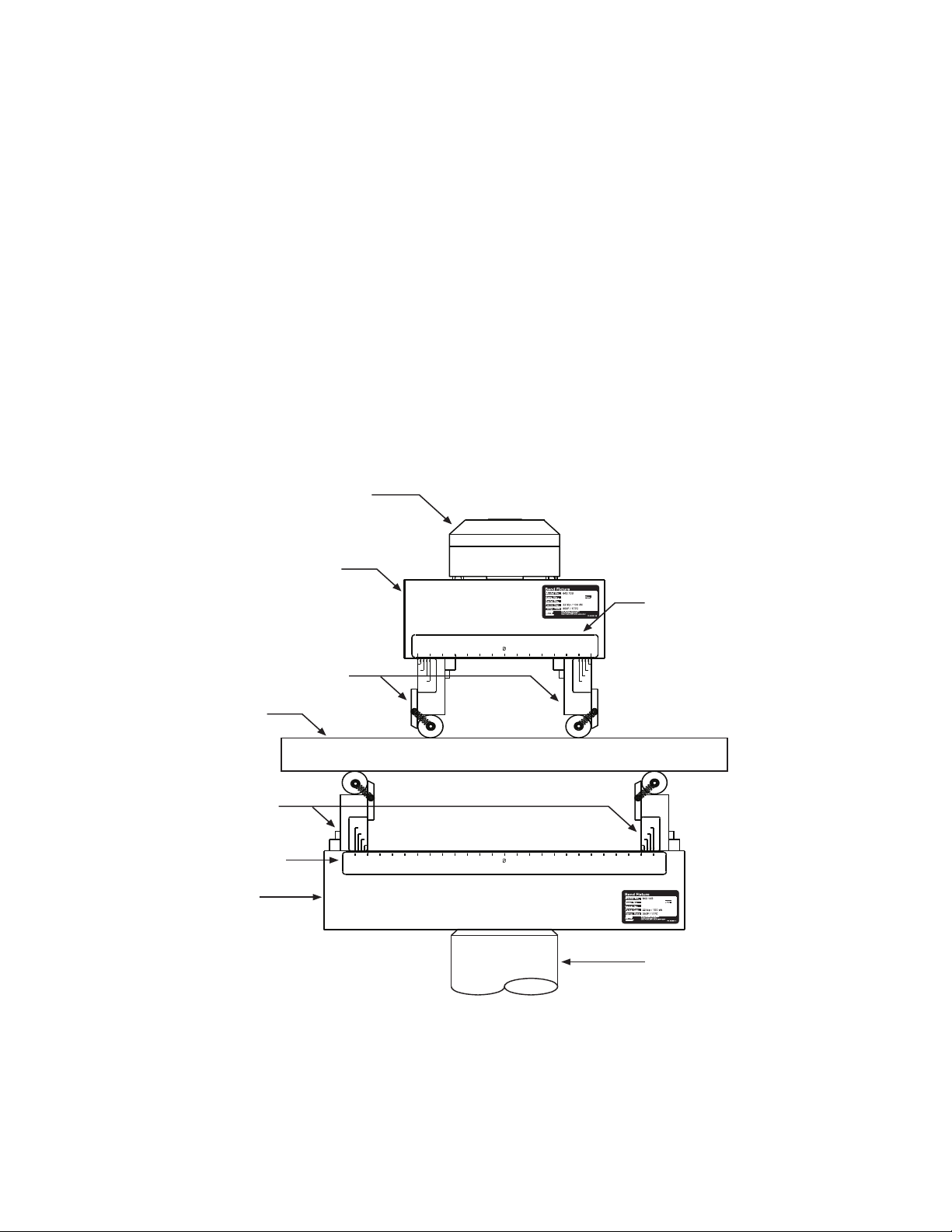
The 642.01, 642.10, and 642.25 can be configured for three-point or four-point
Force Transducer
Upper Bedplate
Adjustable Roller Blocks
Upper Scale
Actuator
Lower
Bedplate
Lower Scale
Adjustable Roller
Blocks
Specimen
loading. Four-point loading uses two roller block assemblies in the upper
bedplate and two in the lower bedplate. Three-point loading uses two roller block
assemblies in the lower bedplate and a three-point option kit attached to the load
cell.
Different diameter rollers can be used with the same roller block assemblies.
Standard roller diameters are 0.125, 0.250, 0.375, 0.500, 0.750, 1.0, 1.25, 1.5,
1.75, and 2.0 inch, as well as 5, 8, 10, 12, 20, 30, 40, and 50 millimeter (see the
tables on pages 14–18 for individual model standard diameters). MTS can also
build rollers with custom sizes. See your sales representative if you require
rollers of non-standard size.
Series 642 Bend Fixture Component Identification
The following illustrations identify the Model 642 Bend Fixture’s major
components in various models and configurations.
Series 642 Bend Fixture Major Components—Four-Point Loading Configuration
14
Introduction
Series 642 Bend Fixtures Product Information
Page 15

Force Transducer
Three-Point Option
Specimen
Lower Fixture Assembly
Actuator
Three-Point Loading Configuration
Series 642 Bend Fixtures Product Information Introduction
15
Page 16

Roller
Retaining Spring
Roller Support
Block
T-Slo t
Adjustment Bolt
Alignment Mark
Bedplate
T-Slot
642.01A Roller Block Assembly
Roller
Roller
Roller Support Block
Retaining Spring
Roller Stop Plate
Alignment Guides
T-Slot Adjustment Bolt
Bedplate
T-Slo t
Roller Block
Clamping Bar
Roller Block Assembly
Adjustment Screw
642.25 Roller Block Assembly
Roller Support
Block
Bedplate
Retaining
Spring
Adjustment Slot
Bedplate
Adjustment Bolt
Alignment
Mark
Roller Support Block
Retaining Wire or
Elastic Band
Roller
642.001 Roller Block Assembly
642.10B Roller Block Assembly
Roller Stop
Plate
Introduction
16
Roller Block Assembly Details
Series 642 Bend Fixtures Product Information
Page 17

Series 642 Bend Fixture Specifications
Dynamic Force
Weight
Dynamic Force
Model Number
642.001 .09 kN (200 lbf)
642.01 10 kN (2.2 kip)
642.10 100 kN (22 kip)
642.25 250 kN (55 kip)
*. Static and dynamic force rating depends upon
the roller diameter.
Dynamic Force
*
Weight
Model Number Weight
kg lb
642.001 0.7 1.5
642.01A 5 10
642.10B 22 48
642.25 60 130
Series 642 Bend Fixtures Product Information Introduction
17
Page 18

Dimensions
Height
(to edge
of roller)
Height
(to edge
of roller)
Length
Span
Span
Length
Model 642.001 Bend Fixture Dimensioning
Model 642.001 Dimensions (SI - Metric Units)
Upper Fixture
Roller Diameter Length Height Minimum Span Maximum Span
1 mm 40.6 25.7 0.4 15.4
2 mm 40.6 26.9 0.4 15.4
3 mm 40.6 26.7 13.7 25
4 mm 40.6 27.9 13.7 25
5 mm 40.6 29.1 13.7 25
Model 642.001 Dimensions (SI - Metric Units)
Lower Fixture
Roller Diameter Length Height Minimum Span Maximum Span
1 mm 75.2 25.7 4.0 50
2 mm 75.2 26.9 4.0 50
3 mm 75.2 26.7 13.7 59.7
18
Introduction
Series 642 Bend Fixtures Product Information
Page 19

Model 642.001 Dimensions (SI - Metric Units)
Height
Span
Span
Length
Length
Lower Fixture
Roller Diameter Length Height Minimum Span Maximum Span
4 mm 75.2 27.9 13.7 59.7
5 mm 75.2 29.1 13.7 59.7
Model 642.01A. 642.10B, and 642.25 Bend Fixture Dimensioning
Model 642.01A Dimensions (part 1 of 2)
Upper Fixture
Roller Diameter Length Height Minimum Span Maximum Span
SI - Metric Units
5 mm 101.6 mm 107.4 mm 23.9 mm 76.2 mm
10 mm 101.6 mm 112.4 mm 23.9 mm 76.2 mm
U.S. Customary
Units
0.125 in. 4.0 in. 4.15 in. 0.94 in. 3.0 in.
Series 642 Bend Fixtures Product Information Introduction
19
Page 20

Model 642.01A Dimensions (part 2 of 2)
Upper Fixture
Roller Diameter Length Height Minimum Span Maximum Span
0.25 in. 4.0 in. 4.28 in. 0.94 in. 3.0 in.
0.5 in. 4.0 in. 4.53 in. 0.94 in. 3.0 in.
Model 642.01A Dimensions
Lower Fixture
Roller Diameter Length Height Minimum
Span
SI - Metric Units
5 mm 177.8 mm 107.4 mm 23.9 mm 152.4 mm
10 mm 177.8 mm 112.4 mm 23.9 mm 152.4 mm
U.S. Customary
Units
0.125 in. 7.0 in. 4.15 in. 0.94 in. 6.0 in.
0.25 in. 7.0 in. 4.28 in. 0.94 in. 6.0 in.
0.5 in. 7.0 in. 4.53 in. 0.94 in. 6.0 in.
Maximum
Span
Model 642.10B Dimensions
Upper Fixture
Roller Diameter Length Height Minimum Span Maximum Span
SI - Metric Units
5 mm 177.8 mm 157.4 mm 58.4 mm 172.4 mm
10 mm 177.8 mm 162.4 mm 53.4 mm 167.4 mm
15 mm 177.8 mm 167.4 mm 48.4 mm 162.4 mm
20 mm 177.8 mm 172.4 mm 43.4 mm 157.4 mm
25 mm 177.8 mm 177.4 mm 38.4 mm 152.4 mm
U.S. Customary
Units
0.25 in. 7.0 in 6.25 in. 2.25 in. 6.75 in.
0.375 in. 7.0 in 6.375 in. 2.125 in. 6.625 in.
0.5 in. 7.0 in 6.5 in. 2.0 in. 6.5 in.
0.750 in. 7.0 in 6.75 in. 1.75 in. 6.25 in.
1.0 in 7.0 in 7.0 in 1.5 in. 6.0 in.
Introduction
20
Series 642 Bend Fixtures Product Information
Page 21

Model 642.10B Dimensions
Lower Fixture
Roller Diameter Length Height Minimum Span Maximum Span
SI - Metric Units
5 mm 368.3 mm 157.4 mm 17.6 mm 284.4 mm
10 mm 368.3 mm 162.4 mm 22.6 mm 289.4 mm
15 mm 368.3 mm 167.4 mm 27.6 mm 294.4 mm
20 mm 368.3 mm 172.4 mm 32.6 mm 299.4 mm
25 mm 368.3 mm 177.4 mm 37.6 mm 304.4 mm
U.S. Customary
Units
0.25 in. 14.5 in. 6.25 in. 0.75 in. 11.25 in.
0.375 in. 14.5 in. 6.375 in. .875 in. 11.375 in.
0.5 in. 14.5 in. 6.5 in. 1.0 in. 11.5 in.
0.750 in. 14.5 in. 6.75 in. 1.25 in. 11.75 in.
1.0 in. 14.5 in. 7.0 in 1.5 in. 12 in.
Model 642.25 Dimensions
Upper Fixture
Roller Diameter Length Height Minimum Span Maximum Span
SI - Metric Units
20 mm 267 mm 300 mm 81 mm 233 mm
30 mm 267 mm 310 mm 71 mm 223 mm
40 mm 267 mm 320 mm 61 mm 213 mm
50 mm 267 mm 330 mm 51 mm 203 mm
U.S. Customary
Units
0.75 in. 10.5 in. 11.75 in. 3.25 in. 9.25 in.
1.0 in. 10.5 in. 12.0 in. 3.0 in. 9.0 in.
1.25 in. 10.5 in. 12.25 in. 2.75 in 8.75 in.
1.5 in. 10.5 in. 12.5 in. 2.5 in. 8.5 in.
1.75 in. 10.5 in. 12.75 in. 2.25 in. 8.25 in.
2.0 in. 10.5 in. 13 in. 2.0 in. 8.0 in.
Series 642 Bend Fixtures Product Information Introduction
21
Page 22

Model 642.25 Dimensions
Lower Fixture
Roller Diameter Length Height Minimum Span Maximum Span
SI - Metric Units
20 mm 673 mm 300 mm 48 mm 580 mm
30 mm 673 mm 310 mm 58 mm 590 mm
40 mm 673 mm 320 mm 68 mm 600 mm
50 mm 673 mm 330 mm 79 mm 610 mm
U.S. Customary Units
0.75 in. 26.5 in. 11.75 in. 1.87 in. 22.75 in.
1.0 in. 26.5 in. 12.0 in. 2.12 in. 23.0 in.
1.25 in. 26.5 in. 12.25 in. 2.37 in. 23.25 in.
1.5 in. 26.5 in. 12.5 in. 2.62 in. 23.5 in.
1.75 in. 26.5 in. 12.75 in. 2.87 in. 23.75 in.
2.0 in. 26.5 in. 13 in. 3.12 in. 24 in.
22
Introduction
Series 642 Bend Fixtures Product Information
Page 23

Safety Information
General Safety Practices: Grips and Fixtures
Typically, grips and fixtures are part of equipment used in MTS testing systems.
This section provides general information about safety issues that pertain to
systems that use grips and fixtures. These issues include statements to the
intended use and foreseeable misuse of the system and definition for the
graphical hazard labeling that is affixed to your product, and other (more general)
safety information that relates to the high-pressure and high-performance
characteristics of MTS servohydraulic and electromechanical systems.
When you prepare to operate a system that includes grips or fixtures, ensure the
following:
• Do not use or allow personnel to operate the system who are not
experienced, trained, or educated in the inherent dangers associated with
high-performance servo hydraulics and who are not experienced, trained, or
educated with regard to the intended operation as it applies to this test
system.
• Do not disable safety components or features (including limit detectors,
light curtains, or proximity switches/detectors).
• Do not attempt to operate the system without appropriate personal safety
gear (for example, hearing, hand, and eye protection).
• Do not modify the system or replace system components using parts that are
not MTS component parts or effect repairs using parts or components that
are not manufactured to MTS specifications.
• Do not operate the grips or fixtures in an explosive atmosphere.
• Do not use the system in a test area where uncontrolled access to the test
system is allowed when the system is in operation.
• For servohydraulic systems, do not operate the system unless an interlock is
installed to monitor supply pressure into the HSM and initiate a system
interlock if a low or no pressure event occurs.
If you have system related responsibilities (that is, if you are an operator, service
engineer, or maintenance person), you should study safety information carefully
before you attempt to perform any test system procedure.
You should receive training on this system or a similar system to ensure a
thorough knowledge of your equipment and the safety issues that are associated
with its use. In addition, you should gain an understanding of system functions
by studying the other manuals supplied with your test system. Contact MTS for
information about the content and dates of training classes that are offered.
It is very important that you study the following safety information to ensure that
your facility procedures and the system’s operating environment do not
contribute to or result in a hazardous situation. Remember, you cannot eliminate
all the hazards associated with this system, so you must learn and remain aware
Series 642 Bend Fixtures Product Information Safety Information
23
Page 24

of the hazards that apply to your system at all times. Use these safety guidelines
WARNING
to help learn and identify hazards so that you can establish appropriate training
and operating procedures and acquire appropriate safety equipment (such as
gloves, goggles, and hearing protection).
Each test system operates within a unique environment which includes the
following known variables:
• Facility variables (facility variables include the structure, atmosphere, and
utilities)
• Unauthorized customer modifications to the equipment
• Operator experience and specialization
• Test specimens
Because of these variables (and the possibility of others), your system can
operate under unforeseen circumstances that can result in an operating
environment with unknown hazards.
Improper installation, operation, or maintenance of your system can result in
hazardous conditions that can cause death, personal injury, or damage to the
equipment or to the specimen. Common sense and a thorough knowledge of the
system’s operating capabilities can help to determine an appropriate and safe
approach to its operation.
The larger capacity grips are heavy.
Dropped grips can cause injury to personnel and damage to equipment.
Be sure to have help or proper lifting devise to position the grips for installation.
Read all manuals Study the contents of this manual and the other manuals provided with your
system before attempting to perform any system function for the first time.
Procedures that seem relatively simple or intuitively obvious may require a
complete understanding of system operation to avoid unsafe or dangerous
situations.
Avoid pinch/crush
points
Pinch points exist between the parts of the grip or fixture that contact the
specimen. Be aware of these pinch points when installing a specimen or working
around the grip or fixture during test setup. High forces generated when grip
pressure is activated can pinch, cut, or crush anything in the path of the grip/
fixture specimen contact area and cause serious injury. Stay clear of any potential
pinch points.
A crush point exists between the grips. Whenever possible, use tongs or similar
tool when handling the specimen during specimen installation. Never allow any
part of your body to enter the path of machine movement or to touch moving
machinery, linkages, hoses, cables, specimens, and so forth. These present
serious crush points or pinch points.
Safety Information
24
Series 642 Bend Fixtures Product Information
Page 25

Locate and read
hazard placards/labels
Find, read, and follow the hazard placard instructions located on the equipment.
These placards are placed strategically on the equipment to call attention to areas
such as known crush points, electrical voltage, and high pressure hazards.
Know facility safe
procedures
Most facilities have internal procedures and rules regarding safe practices within
the facility. Be aware of these safe practices and incorporate them into your daily
operation of the system.
Know controls Before you operate the system for the first time, make a trial run through the
operating procedures with the power off. Locate all hardware and software
controls and know what their functions are and what adjustments they require. If
any control function or operating adjustment is not clear, review the applicable
information until you understand it thoroughly.
Know specimen
properties
The user is responsible for understanding the characteristics of the test specimen.
Be sure to use appropriate personal protective equipment (clothing, hand gloves,
eye protection etc.).
Use protective guards such as cages, enclosures, and special laboratory layouts
when you work with hazardous test specimens (for example, brittle or
fragmenting materials or materials that are internally pressurized).
Have first aid available Accidents can happen even when you are careful. Arrange your operator
schedules so that a properly trained person is always close by to render first aid.
In addition, ensure that local emergency contact information is posted clearly and
in sight of the system operator.
Be aware of
component movement
with hydraulics off
The actuator rod can also drift down when hydraulics are turned off hitting
anything in its path. This uncommanded movement is because of oil movement
between the pressure/return ports and oil blow by across the piston hub. Be aware
that this can happen and clear the area around the actuator rod when hydraulics
are turned off.
Keep bystanders
safely away
Keep bystanders at a safe distance from all equipment. Never allow bystanders to
touch specimens or equipment while the test is running.
Wear proper clothing Do not wear neckties, shop aprons, loose clothing or jewelry, or long hair that
could get caught in equipment and result in an injury. Remove loose clothing or
jewelry and restrain long hair.
Series 642 Bend Fixtures Product Information Safety Information
25
Page 26

Remove flammable
fluids
Remove flammable fluids from their containers or from components before you
install the container or component. If desired, you can replace the flammable
fluid with a non-flammable fluid to maintain the proper proportion of weight and
balance.
Check bolt ratings and
torques
Practice good
housekeeping
Do not exceed the
Maximum Supply
Pressure
Do not disable safety
devices
To ensure a reliable product, fasteners (such as bolts and tie rods) used in MTSmanufactured systems are torqued to specific requirements. If a fastener is
loosened or the configuration of a component within the system is modified, refer
to information in this product manual to determine the correct fastener, fastener
rating, and torque. Overtorquing or undertorquing a fastener can create a
hazardous situation due to the high forces and pressures present in MTS test
systems.
On rare occasions, a fastener can fail even when it is correctly installed. Failure
usually occurs during torquing, but it can occur several days later. Failure of a
fastener can result in a high velocity projectile. Therefore, it is a good practice to
avoid stationing personnel in line with or below assemblies that contain large or
long fasteners.
Keep the floors in the work area clean. Hydraulic fluid that is spilled on any type
of floor can result in a dangerous, slippery surface. Do not leave tools, fixtures,
or other items not specific to the test, lying about on the floor, system, or decking.
For hydraulic grips and fixtures. make sure that the hydraulic supply pressure is
limited to the maximum pressure defined by the grip or fixture identification (ID)
tag.
Your system may have active or passive safety devices installed to prevent
system operation if the device indicates an unsafe condition. Do not disable such
devices as it may result in unexpected system motion.
Provide adequate
lighting
Provide means to
access out-of-reach
components
Wear appropriate
personal protection
Handle chemicals
safely
Ensure adequate lighting to minimize the chance of operation errors, equipment
damage, and personal injury. You need to see what you are doing.
Make sure you can access system components that might be out of reach while
standing on the floor. For example, ladders or scaffolding might be required to
reach load cell connectors on tall load units.
Wear eye protection when you work with high-pressure hydraulic fluid,
breakable specimens, or when anything characteristic to the specimen could
break apart.
Wear ear protection when you work near electric motors, pumps, or other devices
that generate high noise levels. Some systems can create sound pressure levels
that exceed 70 dbA during operation.
Wear appropriate personal protection equipment (gloves, boots, suits, respirators)
whenever you work with fluids, chemicals, or powders that can irritate or harm
the skin, respiratory system, or eyes.
Whenever you use or handle chemicals (for example, cleaning fluids, hydraulic
fluid, batteries, contaminated parts, electrical fluids, and maintenance waste),
refer to the appropriate MSDS documentation for that material and determine the
Safety Information
26
Series 642 Bend Fixtures Product Information
Page 27

appropriate measures and equipment required to handle and use the chemical
safely. Ensure that the chemical is disposed of appropriately.
Know system
interlocks
Interlock devices should always be used and properly adjusted. Interlock devices
are designed to minimize the chance of accidental damage to the test specimen or
the equipment. Test all interlock devices for proper operation immediately before
a test. Do not disable or bypass any interlock devices as doing so could allow
hydraulic pressure to be applied regardless of the true interlock condition. The
Reset/Override button is a software function that can be used to temporarily
override an interlock while attempting to gain control of the system.
Know system limits Never rely on system limits such as mechanical limits or software limits to
protect you or any personnel. System limits are designed to minimize the chance
of accidental damage to test specimens or to equipment. Test all limits for proper
operation immediately before a test. Always use these limits and adjust them
properly.
Do not disturb sensors Do not bump, wiggle, adjust, disconnect, or otherwise disturb a sensor (such as
an accelerometer or extensometer) or its connecting cable when hydraulic
pressure is applied.
Ensure secure cables Do not change any cable connections when electrical power or hydraulic pressure
is applied. If you attempt to change a cable connection while the system is in
operation, an open control loop condition can result. An open control loop
condition can cause a rapid, unexpected system response which can result in
severe personal injury, death, or damage to equipment. Also, ensure that all
cables are connected after you make any changes in the system configuration.
Stay alert Avoid long periods of work without adequate rest. In addition, avoid long periods
of repetitious, unvarying, or monotonous work because these conditions can
contribute to accidents and hazardous situations. If you are too familiar with the
work environment, it is easy to overlook potential hazards that exist in that
environment.
Contain small leaks Do not use your fingers or hands to stop small leaks in hydraulic or pneumatic
hoses. Substantial pressures can build up, especially if the hole is small. These
high pressures can cause the oil or gas to penetrate your skin, causing painful and
dangerously infected wounds. Turn off the hydraulic supply and allow the
hydraulic pressure to dissipate before you remove and replace the hose or any
pressurized component.
Stay clear of moving
equipment/avoid crush
points
Stay clear of mechanical linkages, connecting cables, and hoses that move
because you can get pinched, crushed, tangled, or dragged along with the
equipment. High forces generated by the system can pinch, cut, or crush anything
in the path of the equipment and cause serious injury. Stay clear of any potential
crush points. Most test systems can produce sudden, high-force motion. Never
assume that your reactions are fast enough to allow you to escape injury when a
system fails.
Series 642 Bend Fixtures Product Information Safety Information
27
Page 28

Know the causes of
unexpected actuator
motions
The high force and velocity capabilities of MTS actuators can be destructive and
dangerous (especially if actuator motion is unexpected). The most likely causes
of unexpected actuator response are operator error and equipment failure due to
damage or abuse (such as broken, cut, or crushed cables and hoses; shorted wires;
overstressed feedback devices; and damaged components within the servocontrol
loop). Eliminate any condition that could cause unexpected actuator motion.
Hazard Placard Placement
Hazard placards contain specific safety information and are affixed directly to the
system so they are plainly visible.
Each placard describes a system-related hazard. When possible, international
symbols (icons) are used to graphically indicate the type of hazard and the
placard label indicates its severity. In some instances, the placard may contain
text that describes the hazard, the potential result if the hazard is ignored, and
general instructions about how to avoid the hazard.
The following label is typically found on the bend fixture.
Label Description
Fixture ID plate.
Model SN
Model SN
Assy. Rev
Assy. Rev
Cpty
Cpty
MTS Systems Corporation
14000 Technology Drive
Eden Prairie, MN U.S.A. 55344-2247
kipskN
PN 331078-02
PN 331078-02MTS Systems Corporation
Contains the following information:
• Model number
• Assembly number/Revision
• Capacity
Safety Information
28
Series 642 Bend Fixtures Product Information
Page 29

Installation
WARNING
WARNING
Contents Install Bend Fixtures—Servohydraulic Systems 29
This section discusses the installation of the 642 Bend Fixtures. Two procedures
are provided for installing the bend fixtures:
• One for servohydraulic applications
• One for electromechanical applications
Install Model 642.001 Bend Fixtures—Electromechanical Systems 35
Install Model 642.01, 642.10, and 642.25 Bend Fixtures—
Electromechanical Systems 36
The larger capacity grips are heavy.
Dropped grips can cause injury to personnel and damage to equipment.
Be sure to have help or proper lifting devise to position the grips for installation.
Install Bend Fixtures—Servohydraulic Systems
Follow the steps outlined in the next several pages to install the bend fixtures on
your servohydraulic test system.
Bend fixture installation is inherently dangerous because it takes place
within the crush zone of the force train, when full hydraulic pressure is
applied to the system and actuator movement is required.
Serious personal injury and equipment damage can occur.
Take every precaution to avoid unexpected actuator movement and to avoid
dropping the fixture.
Models 642.001, 642.01, and 642.10 Bend Fixtures install using only cap screws.
The Model 642.25 Bend Fixture uses an adapter plate to bolt to the actuator and
load cell.
Series 642 Bend Fixtures Product Information Installation
29
Page 30

1. Position the crosshead and actuator.
Force Transducer
Upper Bedplate
Mounting Screw
Lower
Bedplate
Mounting
Screw
Actuator
A. Switch on electrical power at your test controller.
B. Apply high hydraulic pressure to the load unit.
C. Position the crosshead and actuator for easy bend fixture installation.
Installation
30
D. Make sure that the crosshead is locked.
E. Turn off hydraulic pressure.
2. Prepare the mounting hardware.
Series 642 Bend Fixtures Product Information
Page 31

Clean and
Lubricate
Force Transducer
Mounting Screw
Mounting
Screw
Actuator
A. Inspect the actuator and force transducer threads. Clean and then
lightly lubricate them with Molykote G-n paste.
B. Do the same with the mounting screws.
3. Install the fixture.
Series 642 Bend Fixtures Product Information Installation
31
Page 32

A. For Model 642.001, 642.01, and 642.10 Bend Fixtures, attach the
For 642.25 attach the adapter plate to
the force transducer first, and then
attach the fixture to the adapter plate
with the provided screws.
Force Transducer
Adapter Plate
642.25 Fixture
Align
Rotate
upper half of the bend fixture to the force transducer with the shorter
mounting screw.
B. Align the fixture with the load unit, and tighten the cap screw(s).
C. For Model 642.01 and 642.10 Bend Fixtures, attach the fixture’s lower
half onto the actuator piston with the longer mounting screw and
tighten it in place. For the 642.25 Bend Fixture attach the adapter plate
to the actuator piston first, and then attach the fixture to the adapter
plate.
You might need to use a spanner wrench on the actuator to keep it from
turning.
32
Installation
Series 642 Bend Fixtures Product Information
Page 33

D. Rotate the actuator to align the fixture’s lower and upper halves.
Loosen
Alig
Rotate
For an anti-rotate actuator, continue on through the next three steps.
E. Unscrew the four cap screws that attach the anti-rotate plate to the
bottom of the piston.
The anti-rotate plate is at the bottom of the actuator, inside the base of
the load unit.
F. Using a spanner wrench, turn the actuator to align the fixture’s lower
half with its upper half.
Series 642 Bend Fixtures Product Information Installation
33
Page 34

G. Tighten the four anti-rotate cap screws to a torque listed in the table
Tighten
below.
The actuator force rating is stamped on an identification plate at the
rear of the load unit.
Anti-Rotate Cap Screw Torque
Actuator Force Rating Torque Rating
25 kN (5.5 kip)
50 to 250 kN (1 to 55 kip)
3.7 N
·m (2.7 lbf·ft)
48 N
·m (35 lbf·ft)
34
Installation
Series 642 Bend Fixtures Product Information
Page 35

Install Model 642.001 Bend Fixtures—Electromechanical Systems
Socket Head
Cap Screw
Pin Adapter
Clevis (Load Unit
Component)
Ensure full
contact
1. Turn the electromechanical toggle switch to the on position. Position the
crosshead as necessary to allow adequate room to install the bend fixtures.
2. Clean the mating parts on the bend fixtures and the load unit.
3. Insert the socket head cap screw through the grip and hand-tighten into the
pin adapter.
4. Insert the pin adapter into the clevis (force transducer attachment fixture,
lower mounting fixture, and so forth). Align the holes in the adapter and the
clevis and insert the pin.
5. Tighten the socket head cap screw to ensure a full contact between the bend
fixture and clevis.
Model 642.001 Bend Fixtures
Series 642 Bend Fixtures Product Information Installation
35
Page 36

Install Model 642.01, 642.10, and 642.25 Bend Fixtures—Electromechanical
Socket Head Cap
Screw
Adapter
Locknut Bearing
Load Unit
Component
Systems
1. Turn the electromechanical toggle switch to the on position. Position the
crosshead as necessary to allow adequate room to install the bend fixtures.
2. Clean the mating parts on the bend fixtures and the load unit.
3. Insert the adapter into the load unit component (force transducer, attachment
fixture, lower mounting fixture, and so forth). Align the holes in the adapter
and the load unit component and insert the pin.
4. Preload this connection by tightening the locknut bearing on the adapter
against the surface of the load unit component. Tighten sufficiently to
ensure that there is no slack during testing.
5. Set the bend fixture on the adapter, align the bend fixture, and secure the
bend fixture to the adapter using the supplied socket head cap screw.
6. Repeat Step 5 for the other bend fixture.
36
Installation
Model 642.01, 642.10, and 642.25 Bend Fixtures
Series 642 Bend Fixtures Product Information
Page 37

Operation
WARNING
Run a Test with Series 642 Bend Fixtures
Running tests with the 642 Bend Fixtures involves the following:
• Positioning the bend fixture halves for specimen installation.
• Adjusting roller block assembly spacing (if needed).
• Installing and centering the specimen on the roller block assemblies.
• Removing the old specimen when the test is done.
1. Position the bend fixture halves.
A. Make sure that the crosshead is locked.
B. Switch on electrical power at your test controller.
C. Apply high hydraulic pressure to the load unit.
If you are installing another new specimen, position the actuator so that
the bend fixture halves are far enough apart for easy specimen
installation. Then skip ahead to step Step 3.
If you are adjusting the roller block assembly spacing, position the
actuator so that the bend fixture’s halves are far enough apart to easily
adjust the spacing. Continue on to step Step 2 before going on to step
Step 3.
2. Adjust the roller block assembly spacing.
A. Remove hydraulic pressure from the load unit.
Your hands are in a crush zone when you adjust roller block assembly
spacing
Your fingers and hands could get crushed.
Make sure you have locked the crosshead and have removed hydraulic pressure
from the load unit.
Series 642 Bend Fixtures Product Information Operation
37
Page 38

Slide
Loosen
Loosen
Slide
Model 642.001 Roller Block Assembly
Model 642.10B Roller Block Assembly
Model 642.25 Roller Block Assembly
Model 642.01A Roller Block Assembly
Slide
Loosen
Slide
Loosen
The Model 642.001, 642.01, and the 642.10 use a T-slot nut and bolt to
attach the roller block assemblies to the bedplate. The 642.25 uses a
clamping bar with a cap screw.
B. Loosen—but don’t fully unscrew—the T-slot bolts, or the cap screws,
on the roller block assemblies you are going to reposition.
C. Slide the assemblies to their new positions. Tighten the T-slot bolts or
cap screws.
3. Install and center the specimen.
A. Make sure that the crosshead is locked.
B. Remove hydraulic pressure from the load unit.
Operation
38
Series 642 Bend Fixtures Product Information
Page 39

Your hands are in a crush zone when you install the specimen
WARNING
Center
WARNING
Your fingers and hands could get crushed.
Make sure you have locked the crosshead and have removed hydraulic pressure
from the load unit.
C. Squarely center the specimen on the lower roller block assemblies.
D. Apply high hydraulic pressure to the load unit.
E. Move the actuator so that the rollers on the upper assemblies just touch
the specimen.
F. Check that the specimen remains centered.
G. If it remains centered, you may begin your test.
H. If it has shifted, perform Steps I through K.
I. Move the actuator so that the upper rollers no longer touch the
specimen.
Your hands are in a crush zone when you position the specimen.
Your fingers and hands could get crushed.
Make sure you have locked the crosshead and have removed hydraulic pressure
from the load unit.
J. Reposition the specimen.
Series 642 Bend Fixtures Product Information Operation
39
Page 40

K. Return to Step D.
WARNING
4. Remove the old specimen.
A. Retract the actuator to open up the bend fixture for easy specimen
removal.
B. Remove hydraulic pressure from the load unit.
Your hands are in a crush zone when you remove the specimen
Your fingers and hands could get crushed.
Make sure you have locked the crosshead and have removed hydraulic pressure
from the load unit.
C. Remove the specimen.
40
Operation
Series 642 Bend Fixtures Product Information
Page 41

Change Rollers—Model 642.001 Bend Fixtures
WARNING
Roller Support Block
Retaining Wire (high-temperature) or
Elastic Band (ambient temperature)
Roller
Small Groove; 1 mm, 2 mm
Large Groove; 3 mm, 4 mm, 5 mm
Note If the bend fixture is not installed in the load unit, skip ahead to Step 5.
1. Make sure the crosshead is locked.
2. Apply high hydraulic pressure to the load unit.
3. Move the actuator so that the bend fixture halves will be far enough apart for
easy roller replacement.
4. Remove hydraulic pressure from the load unit.
Your hands are in a crush zone when you replace the rollers
Your fingers and hands could get crushed.
Make sure that you have locked the crosshead have removed hydraulic pressure
from the load unit.
Series 642 Bend Fixtures Product Information Operation
Model 642.001 Roller Block Assembly
5. Remove the retaining wire or elastic band holding each end of the roller
against the roller support block.
6. Remove the existing roller and replace with the desired size roller. Roller
sizes 1 mm, 2 mm, and 3 mm are placed in the smaller grooves closest to the
center of the bend fixture. The 4 mm and 5 mm rollers fit in the larger
grooves.
7. Replace the retaining clips or elastic bands.
41
Page 42

Change Rollers—642.01, 642.10, and 642.25 Bend Fixtures
WARNING
Lift Out
Unscrew
(both sides)
Note If the bend fixture is not installed in the load unit, skip ahead to Step 5.
1. Make sure that the crosshead is locked.
2. Apply high hydraulic pressure to the load unit.
3. Move the actuator so that the bend fixture halves will be far enough apart for
easy roller replacement.
4. Remove hydraulic pressure from the load unit.
Your hands are in a crush zone when you replace the rollers
Your fingers and hands could get crushed.
Make sure that you have locked the crosshead and have removed hydraulic
pressure from the load unit.
42
Operation
Model 642.10B Roller Block Assembly
5. Unscrew the two roller retainer screws and lift out the old roller.
6. Clean the threads on the retainer screws and give them a very light coating
of Molykote G-n paste.
Series 642 Bend Fixtures Product Information
Page 43

Tighten (both sides)
Install New Roller
642.10B Roller Block Assembly
7. Place the new roller in position. Tighten the retaining screws to hold it in
place.
8. For the Model 642.10 and 642.25 Bend Fixtures, the roller stop plate needs
to be repositioned to conform with the ASTM testing standard being applied
to the test.
Series 642 Bend Fixtures Product Information Operation
43
Page 44

44
Operation
Series 642 Bend Fixtures Product Information
Page 45

Page 46

m
MTS Systems Corporation
14000 Technology Drive
Eden Prairie, Minnesota 55344-2290 USA
Toll Free Phone: 800-328-2255
(within the U.S. or Canada)
Phone: 952-937-4000
(outside the U.S. or Canada)
Fax: 952-937-4515
E-mail: info@mts.com
Internet: www.mts.com
ISO 9001 Certified QMS
 Loading...