

Page 1

be certain.
m
Model 632.85 Biaxial Extensometer
Product Information
011565200 B
Page 2

Copyright information © 2014 MTS Systems Corporation. All rights reserved.
Trademark information MTS is a registered trademark of MTS Systems Corporation within the United
States. These trademarks may be protected in other countries.
All other trademarks or service marks are property of their respective owners.
Publication information
Manual Part Number Publication Date
011565200 A July 1986
011565200 B July 2014
2
Model 632.85 Biaxial Extensometer
Page 3

Contents
Introduction 5
Specifications 7
Safety Information 9
Safety Information Overview 9
Read all manuals 9
Personnel Qualifications 10
System Hazard Zones 10
Avoid Pinch and Crush Points 10
Installation 11
Specimen Mounting 11
Cabling 13
Maintenance 15
Model 632.85 Biaxial Extensometer
3
Page 4

4
Model 632.85 Biaxial Extensometer
Page 5
Introduction
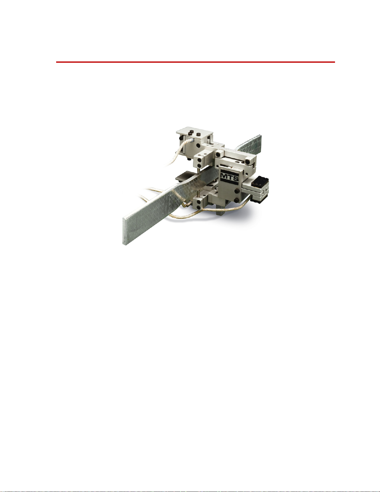
The Model 632.85 Biaxial Extensometer provides axial and transverse outputs
from a single extensometer. The biaxial extensometer is typically used when
performing Poisson ratio testing, composites testing and metal formability
testing.
The extensometer consists of three sensor units. Each sensor unit uses precision
resistance-type, foil strain gages bonded to a metallic element to form a
Wheatstone bridge circuit. Each axial sensor unit uses either a half or full
Wheatstone bridge (depending upon the option selected) to measure axial
deflection. The transverse sensor unit uses a full Wheatstone bridge to measure
the transverse deflection.
Model 632.85 Biaxial Extensometer Introduction
5
Page 6
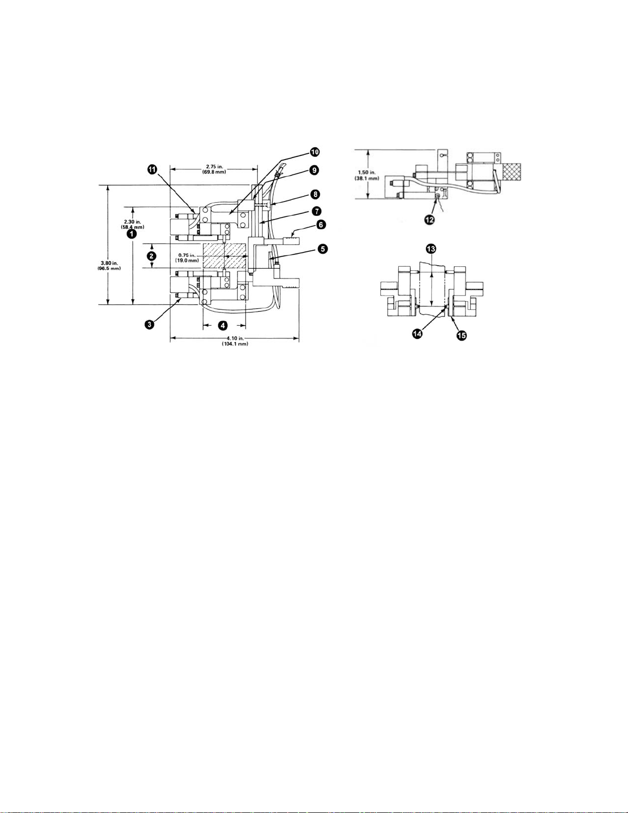
The design of the conical contact points allows the extensometer to be used on a
wide variety of specimens. These same conical points are usable on specimens
with circular as well as rectangular cross sections.
Item
1
2
3
4
5
6
7
8
9
10
11
12
13
14
Description
Plus specimen dimension R
Specimen dimension R
Axial sensor unit A
Specimen dimension S
Transverse sensor unit
Grip pads
Positioning arm
Loosen these screws to adjust for specimen dimension R
Slide bracket
Compliance flexure
Axial sensor unit B
Zero set pin
Axial gage length
Conical point
6
Introduction
15
Overtravel stop plate
Model 632.85 Biaxial Extensometer
Page 7

The extensometer is designed with multiple flexures for the necessary degrees of
compliance to provide for a secure, determinant attachment to the test sample.
This unique patented flexure design (covered by patent number 4,527,335)
provides approximately equal contact force to be transmitted by each of the four
conical contact points. Thus, the extensometer maintains positive contact even
with a somewhat nonuniform test sample or one which deflects somewhat
nonuniformly under static or dynamic loading.
Option 001 provides an averaged axial output to a dc conditioner. This
extensometer consists of a half Wheatstone bridge in each of the two axial sensor
units to measure the axial deflection of the specimen and a full Wheatstone
bridge in the transverse sensor unit to measure the transverse deflection of the
specimen. The two half bridges are output-matched (to within 1% of each other)
and combined into a full bridge to provide a single averaged axial output which
can be conditioned by a single dc controller or dc conditioner. The transverse
sensor unit uses a full Wheatstone bridge to measure the transverse deflection.
Two dc conditioners with their associated calibrated ranges are required to
condition the output signals from this unit.
Option 002 provides a dual axial output to the dc conditioners. This extensometer
contains a full Wheatstone bridge in each of the two axial sensor units to measure
axial deflection on both sides of the specimen independently. The transverse
deflection is also measured by a full Wheatstone bridge in the transverse sensor
unit. The output of each gage is cabled directly to its respective dc conditioner.
This configuration is particularly useful when it is necessary to measure bending
strains on the specimen. Three dc conditioners with their associated calibrated
ranges are required to condition the output signals from this unit.
Specifications
Parameter Specification - 632.85F-05
Specimen size range
Flat specimen
Dimension (R):
Dimension (S):
Round specimen
Diameter
Travel
Axial:
Transverse:
Axial gage length:
Accuracy (ISO 9513):
Temperature range:
Contact force of each contact on
specimen at mid-transverse
range:
* Specimen size range dimensions correspond to those shown in
previous figure.
*
0.5 to 51 mm
1 to 34 mm
3 to 34 mm
+1.2 to -1.5 mm
+/- 0.5 mm
25.00 mm
class 0,5
°C to +150 °C
-100
700 grams
Model 632.85 Biaxial Extensometer Introduction
7
Page 8

8
Introduction
Model 632.85 Biaxial Extensometer
Page 9

Safety Information
Safety Information Overview
Extensometers are used to provide specimen feedback in material test systems.
Operators using extensometers should be aware of the system level safety
information. Test systems are designed to generate single-axis or multi-axial
motions and forces simultaneously in a controlled laboratory environment and
impart these motions and forces into a test specimen that is secured to the system.
When you prepare to operate the system and during system operation, ensure the
following:
• Do not use or allow personnel to operate the system who are not
experienced, trained, or educated in the inherent dangers associated with
high-performance servo hydraulics and who are not experienced, trained, or
educated with regard to the intended operation as it applies to this test
system.
• Do not disable safety components or features (including limit detectors,
light curtains, or proximity switches/detectors).
• Do not attempt to operate the system without appropriate personal safety
gear (for example, hearing, hand, and eye protection).
Read all manuals
• Do not apply energy levels that exceed the maximum energies and velocities
for the system design. Refer to the system specifications.
• Do not test a specimen that exceeds the minimum (if applicable) or
maximum allowable mass. Refer to the system specifications.
• Do not use specimens that are combustible, flammable, pressurized, or
explosive.
• Do not modify the system or replace system components using parts that are
not MTS component parts or effect repairs using parts or components that
are not manufactured to MTS specifications.
• Do not operate the system in an explosive atmosphere.
• Do not use the system in a test area where uncontrolled access to the test
system is allowed when the system is in operation.
Study the contents of this manual and the other manuals provided with your
system before attempting to perform any system function for the first time.
Procedures that seem relatively simple or intuitively obvious may require a
complete understanding of system operation to avoid unsafe or dangerous
situations.
Model 632.85 Biaxial Extensometer Safety Information
9
Page 10

Personnel Qualifications
Do not allow unqualified personnel to perform any of the system
maintenance, setup, or operating procedures.
Operation and maintenance of the system by unqualified personnel can
expose them and others to hazards that can cause damage to equipment
and injury or death.
The system maintenance, setup, and operating procedures should only to be
performed by trained personnel. MTS offers training classes that provide the
necessary skills training.
System Hazard Zones
The area around and including the test system is considered hazardous.
Generally, hazards result from motions that occur during system operation.
However, there are latent pressure, overturning, and settling/unexpected
movement hazards that can occur prior to or after system operation, during
specimen installation, or during maintenance and repair.
The hazard zone includes the entire system and an additional area of at least 1
meter (3.3 feet) around the system perimeter. In addition, the hazard zone should
be extended to include the optional hydraulic power source (when purchased)
and any associated hoses, cables, and hardline.
Whenever personnel enter this defined zone they should be outfitted with
adequate and appropriate safety attire including hearing protection, safety
glasses, hard hat, and safety shoes. Never wear loose fitting clothing when in the
test area. Never enter the test area when hydraulics are on.
Avoid Pinch and Crush Points
When possible, install the extensometer on the specimen before installing the
specimen in the grips. Pinch points exist between the parts of the grip or fixture
that contact the specimen. Be aware of these pinch points when installing a
specimen or working around the grip or fixture during test setup. High forces
generated when grip pressure is activated can pinch, cut, or crush anything in the
path of the grip/ fixture specimen contact area and cause serious injury. Stay clear
of any potential pinch points.
A crush point exists between the grips. Whenever possible, use tongs or similar
tool when handling the specimen during specimen installation. Never allow any
part of your body to enter the path of machine movement or to touch moving
machinery , linkages, hoses, cables, specimens, and so forth. These present
serious crush points or pinch points.
Safety Information
10
Model 632.85 Biaxial Extensometer
Page 11

Installation
Specimen Mounting
The extensometer is mounted on the specimen by the use of the conical points.
Perform the following procedure to mount the extensometer on a specimen.
Item Description
1
2
3
4
5
6
7
8
9
10
11
12
Axial sensor unit A
R dimension
Axial sensor unit B
Compliance flexure
Remove screws on underside of compliance flexure to
separate the slide bracket form the compliance flexure.
Slide bracket
Loosen these screws to adjust for specimen dimension R
Positioning arm
Grip pads
Location for zero set spacer
Transverse sensor unit
Axial gage length
Model 632.85 Biaxial Extensometer Installation
11
Page 12

Item Description
13
14
15
16
Overtravel stop plate
Conical point contact
Conical point vertical adjustment
Zero set pin
1. Ensure the zero set pins are installed in the extensometer (refer to above
figure).
2. Slightly loosen the socket head cap screws which secure axial sensor unit B
to the positioning arm.
Note For specimens where the R dimension (refer to the specifications
section) is greater than 1.1 in. (28 mm), perform steps 3 through 5 to set
the extensometer transverse gage length. If the specimen has a R
dimension less than 1.1 in. (28 mm), proceed to step 6.
3. Remove the two socket head cap screws which secure the slide bracket to
the axial sensor unit B compliance flexure.
4. Slide the slide bracket off from the positioning arm. Turn the slide bracket
180° and slide it back onto the positioning arm. Note that the section of the
slide bracket which was secured to the top of the compliance flexure will
now be secured to the underside of the compliance flexure.
5. Place the compliance flexure in place on top of the extended side section of
the slide bracket. Replace the socket head cap screws removed in step 3 to
the underside of the slide bracket. Secure the slide bracket to the compliance
flexure by tightening the socket head cap screws.
6. Insert the zero set spacer behind the mechanical stop of the transverse
sensor. The zero set spacer is designed to hold the transverse output to zero
volts. Measure the transverse conditioner output and verify that the
conditioner output is 0 V± 2 V.
Note The extensometer might want to swing and twist very thin specimens. T o
restrain the extensometer, connect a string between the grip pad and the
load frame column.
7. Slide the axial sensor unit B along the positioning arm until the conical
points contact the specimen. Hold the extensometer in position and tighten
the socket head cap screws.
8. Remove the zero set spacer installed in step 6.
9. Adjust the placement of the conical points on the specimen to
align the upper and lower contact points on the vertical center
line of the specimen.
12
Installation
Model 632.85 Biaxial Extensometer
Page 13

Cabling
Shunt
R4
Shunt
R3
Red
Green
White
Black
+ Excitation
- Excitation
+ Output
- Output
Shield
1
2
3
4
A
B
C
D
E
F
The cable connector for the 632.85F is a PT01A-10-6P. The mating connector
should be a PT06A-10-6S. Shown below is a representation of the connector and
the wiring diagram.
Model 632.85 Biaxial Extensometer Installation
13
Page 14

14
Installation
Model 632.85 Biaxial Extensometer
Page 15

Maintenance
The conical points must be properly aligned to minimize the crosstalk between
the sensor units. Perform the following procedure to align the conical points.
Item Description
1
2
3
4
5
6
7
8
Conical point trim adjustment (lower)
Overtravel stop plate (2)
Flush adjustment of conical point
Axial gage length
Conical point trim adjustment (upper)
Conical alignment fixture shown for trim adjustment
Trim adjustment slot
Conical alignment fixture shown for flush alignment
1. Ensure the zero set pins are installed in the extensometer.
2. Refer to the installation drawing supplied with the extensometer. Check the
drawing to determine if the contact points are to be flush mounted or require
a specified trim adjustment.
Model 632.85 Biaxial Extensometer Maintenance
15
Page 16

Note If the conical points require flush mounting, perform step 3A. If the
contact points require a trim adjustment, perform step 3B.
3. Place the flat end of the alignment fixture against the side of the sensor unit
containing the replacement conical point (refer to above figure). Move the
conical point until the flat end is flush to the flat surface of the alignment
fixture.
4. Position the alignment fixture against the side of the sensor unit containing
the conical point so that the flat end of the contact point can extend into the
trim adjustment slot (refer to above figure). Move the contact point into the
trim adjust slot until the flat end is positioned as specified in the installation
drawing.
5. Firmly tighten the two conical point hold down screws.
6. Repeat this procedure for any other replacement conical point.
7. Remove the zero set pins.
16
Maintenance
Model 632.85 Biaxial Extensometer
Page 17

Page 18

m
MTS Systems Corporation
14000 Technology Drive
Eden Prairie, Minnesota 55344-2290 USA
Toll Free Phone: 800-328-2255
(within the U.S. or Canada)
Phone: 952-937-4000
(outside the U.S. or Canada)
Fax: 952-937-4515
E-mail: info@mts.com
http://www.mts.com
ISO 9001 Certified QMS
 Loading...