

Page 1

be certain.
m
Series 609 Alignment Fixture
Product Information
015-031-901 E
Page 2

Copyright information © 1993, 1999, 2001, 2008 MTS Systems Corporation. All rights reserved.
Trademark information MTS is a registered trademark of MTS Systems Corporation within the United
States. This trademark may be protected in other countries.
Publication information
Manual Part Number Publication Date
150319-01 A August 1993
015-031-901 B September 1999
015-031-901 C February 2001
015-031-901 D November 2001
015-031-901 E March 2008
2
Manual Template 4.3
Page 3

Contents
Technical Support 5
How to Get Technical Support 5
Before You Contact MTS 5
If You Contact MTS by Phone 6
Problem Submittal Form in MTS Manuals 7
Preface 9
Before You Begin 9
Conventions 10
Documentation Conventions 10
Introduction 13
Misalignment 15
About Concentric Misalignment 15
Adjust Concentric Alignment 16
About Angular Misalignment 17
Adjust Angular Alignment 18
Safety Information 21
Hazard Placard Placement 21
Installation 23
Series 609 Alignment Fixture Product Information Contents
3
Page 4

Specimen Preparation 29
About Gaged Specimens 29
Round Thick Diameter Specimens 31
Calculating Bending Strain—Round Thick Diameter Specimens 32
Round Thin Diameter Specimens 34
Calculating Bending Strain—Round Thin Diameter Specimens 35
Flat Thick Specimens 37
Calculating Bending Strain—Flat Thick Specimens 38
Flat Thin Specimens 40
Calculating Bending Strain—Flat Thin Specimens 41
Notched Round Thick Diameter Specimens 42
Calculating Bending Strain—Notched Round Thick Diameter Specimens 43
Notched Round Thin Diameter Specimens 44
Calculating Bending Strain—Notched Round Thin Diameter Specimens 45
Notched Flat Thick Specimens 48
Calculating Bending Strain—Notched Flat Thick Specimens 49
Notched Thin Flat Specimens 51
Calculating Bending Strain—Notched Thin Flat Specimens 52
Alignment Procedure 55
Installing a Gaged Specimen 56
Adjust the Concentric Alignment 58
Adjust the Angular Alignment 63
Check the Alignment 67
4
Contents
Series 609 Alignment Fixture Product Information
Page 5

Technical Support
How to Get Technical Support
How to Get Technical Support
Start with your
manuals
Technical support
methods
MTS web site
www.mts.com
E-mail techsupport@mts.com
Telephone MTS Call Center 800-328-2255
Fax 952-937-4515
The manuals supplied by MTS provide most of the information you need to use
and maintain your equipment. If your equipment includes MTS software, look
for online help and README files that contain additional product information.
If you cannot find answers to your technical questions from these sources, you
can use the internet, e-mail, telephone, or fax to contact MTS for assistance.
MTS provides a full range of support services after your system is installed. If
you have any questions about a system or product, contact MTS in one of the
following ways.
The MTS web site gives you access to our technical support staff by means of a
Technical Support link:
www.mts.com > Contact Us > Service & Technical Support
Weekdays 7:00 A.M. to 5:00 P.M., Central Time
Please include “Technical Support” in the subject line.
Before You Contact MTS
MTS can help you more efficiently if you have the following information
available when you contact us for support.
Know your site
number and system
number
Series 609 Alignment Fixture Product Information Technical Support
The site number contains your company number and identifies your equipment
type (material testing, simulation, and so forth). The number is usually written on
a label on your MTS equipment before the system leaves MTS. If you do not
have or do not know your MTS site number, contact your MTS sales engineer.
Example site number: 571167
When you have more than one MTS system, the system job number identifies
which system you are calling about. You can find your job number in the papers
sent to you when you ordered your system.
Example system number: US1.42460
5
Page 6

If You Contact MTS by Phone
Know information from
prior technical
If you have contacted MTS about this problem before, we can recall your file.
You will need to tell us the:
assistance
• MTS notification number
• Name of the person who helped you
Identify the problem Describe the problem you are experiencing and know the answers to the
following questions:
• How long and how often has the problem been occurring?
• Can you reproduce the problem?
• Were any hardware or software changes made to the system before the
problem started?
• What are the model numbers of the suspect equipment?
• What model controller are you using (if applicable)?
• What test configuration are you using?
Know relevant
computer information
If you are experiencing a computer problem, have the following information
available:
• Manufacturer’s name and model number
• Operating software type and service patch information
• Amount of system memory
• Amount of free space on the hard drive in which the application resides
• Current status of hard-drive fragmentation
• Connection status to a corporate network
Know relevant
For software application problems, have the following information available:
software information
• The software application’s name, version number, build number, and if
available, software patch number. This information is displayed briefly
when you launch the application, and can typically be found in the “About”
selection in the “Help” menu.
• It is also helpful if the names of other non-MTS applications that are
running on your computer, such as anti-virus software, screen savers,
keyboard enhancers, print spoolers, and so forth are known and available.
If You Contact MTS by Phone
Your call will be registered by a Call Center agent if you are calling within the
United States or Canada. Before connecting you with a technical support
specialist, the agent will ask you for your site number, name, company, company
address, and the phone number where you can normally be reached.
Technical Support
6
Series 609 Alignment Fixture Product Information
Page 7

Problem Submittal Form in MTS Manuals
If you are calling about an issue that has already been assigned a notification
number, please provide that number. You will be assigned a unique notification
number about any new issue.
Identify system type To assist the Call Center agent with connecting you to the most qualified
technical support specialist available, identify your system as one of the
following types:
• Electromechanical materials test system
• Hydromechanical materials test system
• Vehicle test system
• Vehicle component test system
• Aero test system
Be prepared to
Prepare yourself for troubleshooting while on the phone:
troubleshoot
• Call from a telephone when you are close to the system so that you can try
implementing suggestions made over the phone.
• Have the original operating and application software media available.
• If you are not familiar with all aspects of the equipment operation, have an
experienced user nearby to assist you.
Write down relevant
Prepare yourself in case we need to call you back:
information
• Remember to ask for the notification number.
• Record the name of the person who helped you.
• Write down any specific instructions to be followed, such as data recording
or performance monitoring.
After you call MTS logs and tracks all calls to ensure that you receive assistance and that action
is taken regarding your problem or request. If you have questions about the status
of your problem or have additional information to report, please contact MTS
again and provide your original notification number.
Problem Submittal Form in MTS Manuals
Use the Problem Submittal Form to communicate problems you are experiencing
with your MTS software, hardware, manuals, or service which have not been
resolved to your satisfaction through the technical support process. This form
includes check boxes that allow you to indicate the urgency of your problem and
your expectation of an acceptable response time. We guarantee a timely
response—your feedback is important to us.
The Problem Submittal Form can be accessed:
• In the back of many MTS manuals (postage paid form to be mailed to MTS)
• www.mts.com > Contact Us > Problem Submittal Form (electronic form to
be e-mailed to MTS)
Series 609 Alignment Fixture Product Information Technical Support
7
Page 8

Problem Submittal Form in MTS Manuals
Technical Support
8
Series 609 Alignment Fixture Product Information
Page 9

Before You Begin
Preface
Before You Begin
Safety first! Before you attempt to use your MTS product or system, read and understand the
Safety manual and any other safety information provided with your system.
Improper installation, operation, or maintenance of MTS equipment in your test
facility can result in hazardous conditions that can cause severe personal injury or
death and damage to your equipment and specimen. Again, read and understand
the safety information provided with your system before you continue. It is very
important that you remain aware of hazards that apply to your system.
Other MTS manuals In addition to this manual, you may receive additional MTS manuals in paper or
electronic form.
If you have purchased a test system, it may include an MTS System
Documentation CD. This CD contains an electronic copy of the MTS manuals
that pertain to your test system, including hydraulic and mechanical component
manuals, assembly drawings and parts lists, and operation and preventive
maintenance manuals. Controller and application software manuals are typically
included on the software CD distribution disc(s).
Series 609 Alignment Fixture Product Information Preface
9
Page 10

Conventions
DANGER
WARNING
CAUTION
Conventions
Documentation Conventions
The following paragraphs describe some of the conventions that are used in your
MTS manuals.
Hazard conventions As necessary, hazard notices may be embedded in this manual. These notices
contain safety information that is specific to the task to be performed. Hazard
notices immediately precede the step or procedure that may lead to an associated
hazard. Read all hazard notices carefully and follow the directions that are given.
Three different levels of hazard notices may appear in your manuals. Following
are examples of all three levels.
Note For general safety information, see the safety information provided with
your system.
Danger notices indicate the presence of a hazard with a high level of risk which,
if ignored, will result in death, severe personal injury, or substantial property
damage.
Warning notices indicate the presence of a hazard with a medium level of risk
which, if ignored, can result in death, severe personal injury, or substantial
property damage.
Caution notices indicate the presence of a hazard with a low level of risk which,
if ignored, could cause moderate or minor personal injury, equipment damage, or
endanger test integrity.
Notes Notes provide additional information about operating your system or highlight
easily overlooked items. For example:
Note Resources that are put back on the hardware lists show up at the end of
the list.
Special terms The first occurrence of special terms is shown in italics.
Illustrations Illustrations appear in this manual to clarify text. It is important for you to be
Electronic manual
conventions
Preface
10
aware that these illustrations are examples only and do not necessarily represent
your actual system configuration, test application, or software.
This manual is available as an electronic document in the Portable Document
File (PDF) format. It can be viewed on any computer that has Adobe Acrobat
Reader installed.
Series 609 Alignment Fixture Product Information
Page 11

Documentation Conventions
Hypertext links The electronic document has many hypertext links displayed in a blue font. All
blue words in the body text, along with all contents entries and index page
numbers, are hypertext links. When you click a hypertext link, the application
jumps to the corresponding topic.
Series 609 Alignment Fixture Product Information Preface
11
Page 12

Documentation Conventions
12
Preface
Series 609 Alignment Fixture Product Information
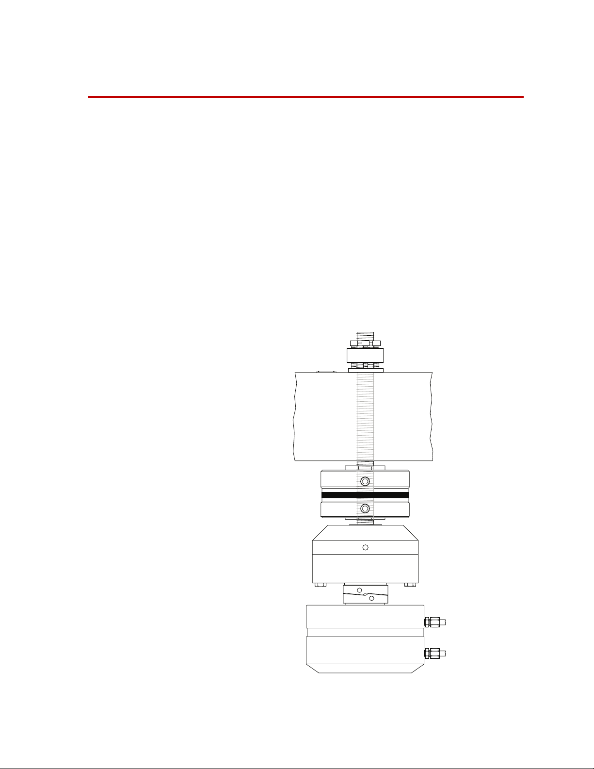
Page 13
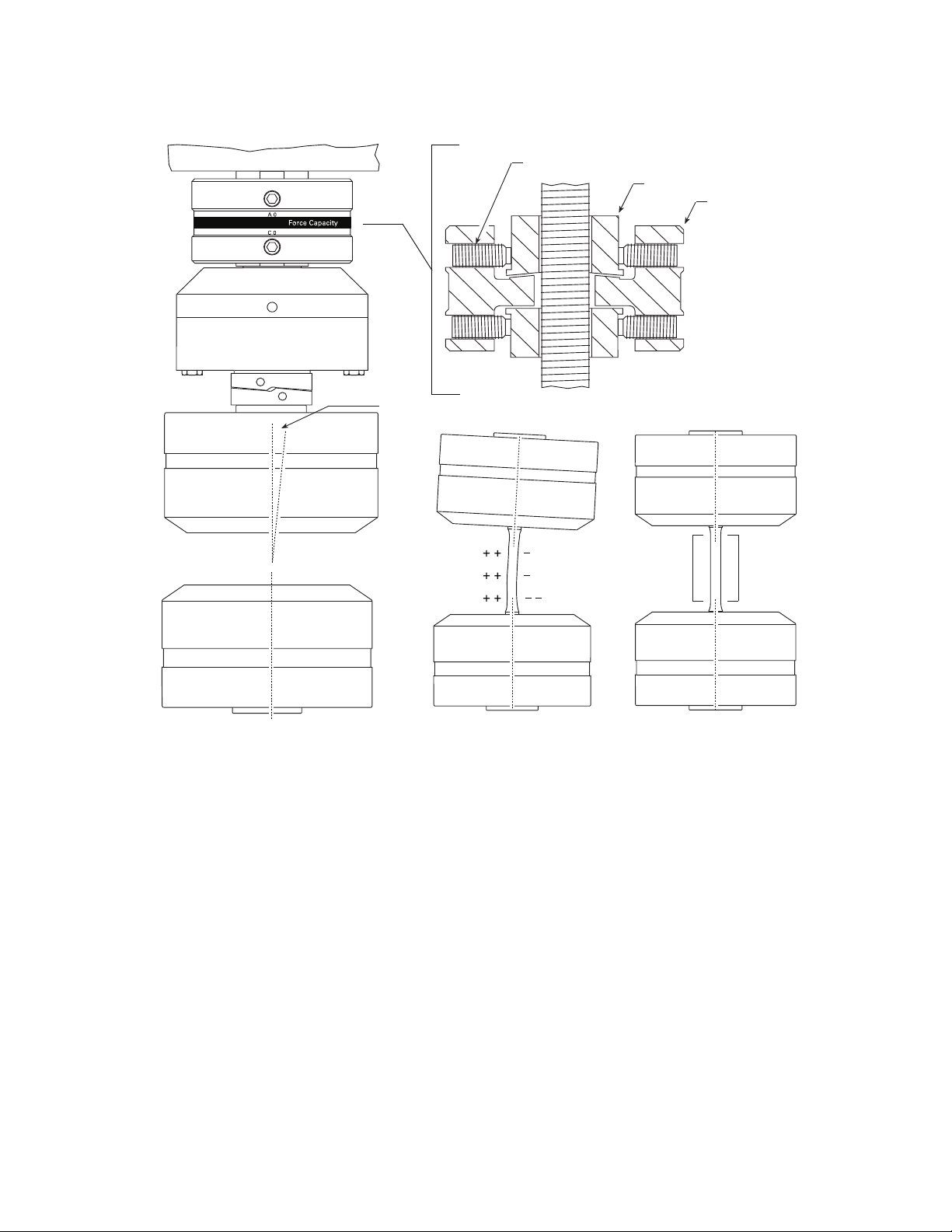
Introduction
C 0
A 0
Force Capacity
Contents Misalignment 15
The MTS Series 609 Alignment Fixture improves alignment between the upper
and lower grips of your load unit. Improving alignment reduces bending strains
in your specimen, which produces more accurate test results. This section
discusses the consequences of having misaligned grips and the two types of
adjustments that can compensate for misalignment problems:
• One set of adjustments compensates for concentric misalignment.
• One set of adjustments compensates for angular misalignment.
In a typical installation, the Series 609 Alignment Fixture is installed between the
force transducer and crosshead.
About Concentric Misalignment 15
About Angular Misalignment 17
Model 609 Alignment Fixture
Series 609 Alignment Fixture Product Information Introduction
13
Page 14

What you need to
know
MTS Systems Corporation assumes that you know how to use your controller.
See the appropriate manual for information about performing any controllerrelated step in the procedures in this manual. You are expected to know how to do
the following procedures:
• Turn hydraulic pressure on and off.
• Select a control mode.
• Manually adjust the actuator position.
• Install a specimen.
• Define a simple test.
• Run a test.
Related products The Series 609 Alignment Fixture is related to other products. See the following
product information manuals for product-specific information and procedures.
• Your load unit manual has information about installing the force transducer.
• Your grip manual has information about installing the grips.
• An option for the alignment fixture is an alignment software package which
is used with the fixture. See the Using 709 Easy Alignment manual.
14
Introduction
Series 609 Alignment Fixture Product Information
Page 15
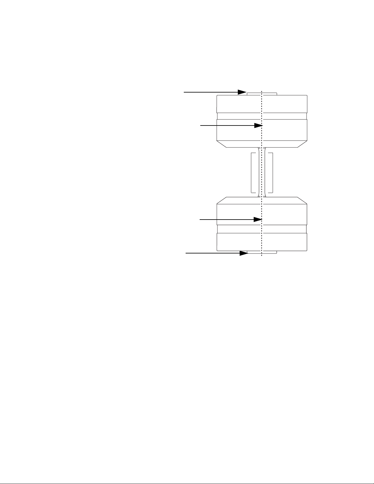
Misalignment
Mounting Surface
Mounting Surface
Equal Strain Equal Strain
Loading Axis
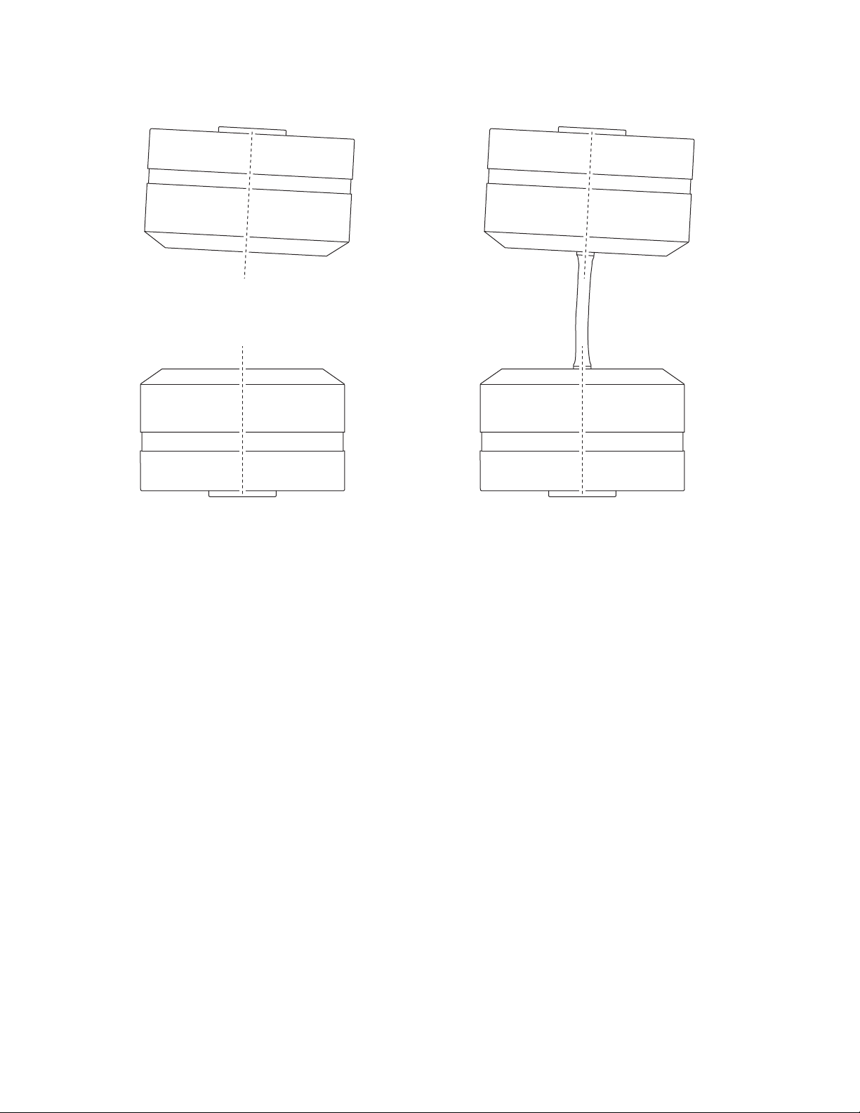
Loading Axis
Misalignment
In uniaxial testing, perfectly aligned grips produce uniform axial tensile strains in
a specimen. For grips to be perfectly aligned, their loading axes must be
concentric.
Perfectly Aligned Grips Produce Uniform Axial Strains
Misalignment between the grips produces nonuniform axial strains in a
specimen. Some areas will have higher than average strains; other areas lower
than average strains. Bending strain is the difference between the average strain
and areas with higher or lower than average strains.
Many ASTM procedures limit maximum bending strains because they cause
specimens to exhibit much lower strengths than if all axial strains were uniform.
The alignment fixture lets you reduce bending strains by improving concentric
and angular alignment between the upper and lower grips.
Grips can have concentric and angular misalignments. Both can occur together
and have a combined effect on the bending strains that appear in the specimen.
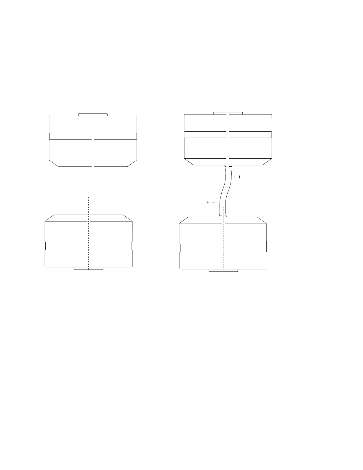
About Concentric Misalignment
Concentric misalignment shifts the vertical axes of the grips laterally away from
each other. This puts an “S” shaped bend in the specimen.
A specimen with an “S” bend has a zero bending strain in the middle of its gage
section. It has higher than average bending strains at the top and bottom of its
Series 609 Alignment Fixture Product Information Introduction
15
Page 16
Adjust Concentric Alignment
Higher Than Average Strain
Lower Than Average Strain
gage section. These higher strains are on opposite sides. It also has lower than
average bending strains at the top and bottom of its gage section, opposite the
higher strains.
Actual strain readings vary with the amount of tensile load applied to the
specimen. With zero or low tensile force applied to the specimen, tensile strain
readings can be opposite compressive strain readings. Under higher tensile force,
high tensile readings can be opposite lower tensile readings.
Concentric Misalignment Produces an “S” Bend
Adjust Concentric Alignment
Turning the four lower adjustment screws moves the concentricity collar. Moving
the collar laterally shifts the upper grip’s position. This aligns the grips’
centerlines, improving their concentric alignment.
The effect of improved concentricity on a specimen is to reduce its “S” bend and
the strains that go with this bend.
As “S” bend strains fade into the background, “C” bend strains come to the
foreground. (Remember that concentric and angular misalignment can occur
together, putting “S” and “C” bends into the same specimen.)
For many test procedures, removing the “S” bend alone may be enough to get
your bending strains within specifications.
Introduction
16
Series 609 Alignment Fixture Product Information
Page 17
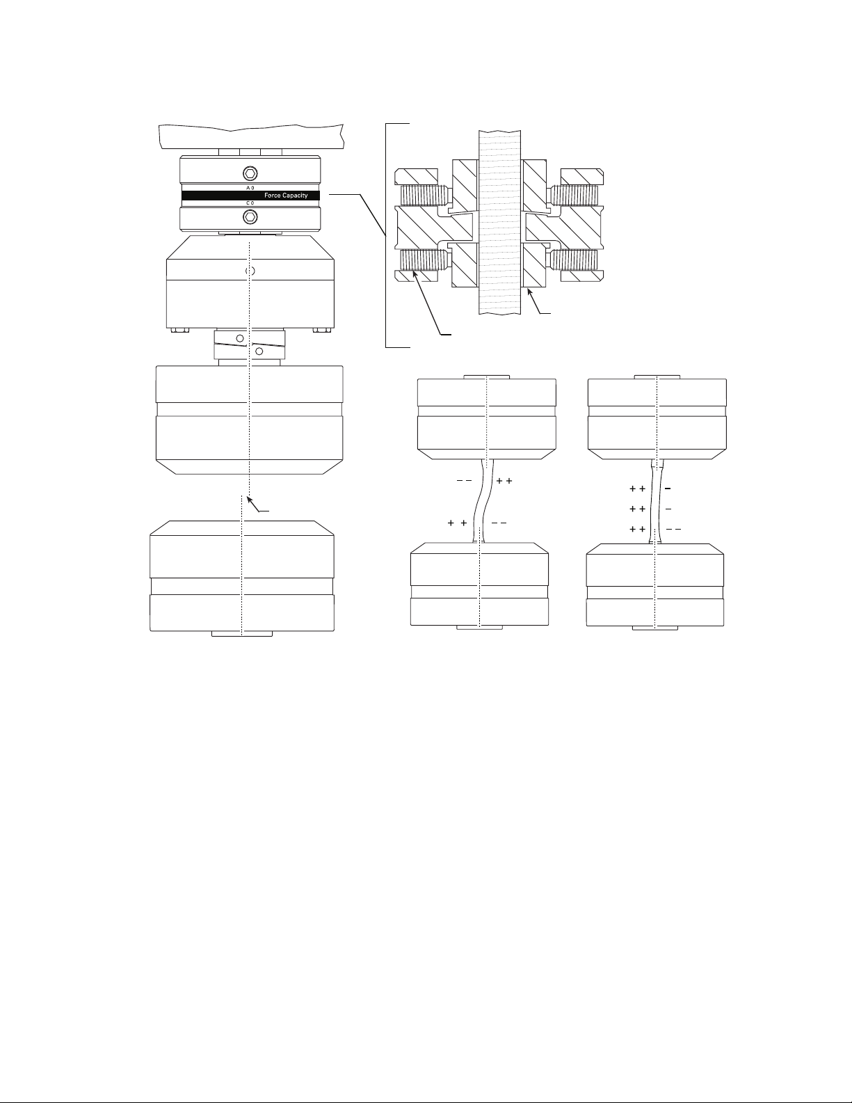
About Angular Misalignment
Concentricity Collar
Concentricity Adjustment Screws
Before and After
Concentric
Adjustment
Misalignment
Improving Concentric Alignment
About Angular Misalignment
Angular misalignment angles the upper grip’s loading axis away from the lower
grip’s loading axis. This misalignment puts a “C”-shaped bend in the specimen.
A specimen with a “C” bend has a side with higher than average strains and a
side opposite with lower than average strains. The bending strain is uniform over
the entire gage section.
Again, actual strain readings vary with the amount of tensile load applied to the
specimen.
With zero or low tensile force applied to the specimen, you can have tensile
readings on one side of the specimen and compressive strain readings on the
other side of the specimen.
Under higher tensile force, you can have higher tensile readings on one side of
the specimen and lower tensile readings on the other side of the specimen.
Series 609 Alignment Fixture Product Information Introduction
17
Page 18
Adjust Angular Alignment
+ +
+ +
+ +
Angular Misalignment Produces a “C” Bend
Adjust Angular Alignment
Turning the four upper adjustment screws against the angularity collar moves the
housing. The mating surfaces of the angularity collar and housing are spherical.
This tilts the housing as it moves. This tilt gets the grips’ faces parallel,
improving their angular alignment.
Improved angularity reduces the specimen’s “C” bend and the strains that go with
this bend.
Removing the “C” bend can create another “S” bend which may need to be
reduced.
You may have to go back and forth between reducing the “S” bend and reducing
the “C” bend to get the bending strain within specifications.
18
Introduction
Series 609 Alignment Fixture Product Information
Page 19
Adjust Angular Alignment
Housing
Angularity Collar
Angularity Adjustment Screws
Equal
Strain
Equal
Strain
Before and After Angular Adjustment
Misalignment
Improving Angular Alignment
Series 609 Alignment Fixture Product Information Introduction
19
Page 20

Adjust Angular Alignment
20
Introduction
Series 609 Alignment Fixture Product Information
Page 21
Safety Information
Serial No.
Rev.
Model No.
Part No.
PN 491909-01
PN 491906-01
MTS Systems Corporation
14000 Technology Drive
Eden Prairie, MN USA 55344
609 Alignment Fixture
Force Capacity:
100 kN / 22 kip
Model No.
Part No.
Serial No.
Rev.
Hazard Placard Placement
Hazard placards contain specific safety information and are affixed directly to the
system so they are plainly visible.
Each placard describes a system-related hazard. When possible, international
symbols (icons) are used to graphically indicate the type of hazard and the
placard label indicates its severity. In some instances, the placard may contain
text that describes the hazard, the potential result if the hazard is ignored, and
general instructions about how to avoid the hazard.
The following labels are typically located on the alignment fixture.
L
ABEL DESCRIPTION
Alignment Fixture ID label.
Hazard Placard Placement
Part # 049-190-901
Contains the following information:
• Model number
• Part number
• Serial Number
• Revision
Part # 049-190-601
Alternate ID label.
Contains the following information:
• Model number
• Part number
• Serial Number
• Revision
Series 609 Alignment Fixture Product Information Safety Information
21
Page 22

Hazard Placard Placement
Safety Information
22
Series 609 Alignment Fixture Product Information
Page 23

Installation
Stud
Preload Nut
Washer
Adapter Bushing
Stud
Jackbolts (6)
Preload Nut
Washer
Crosshead
Alignment Fixture
Force Transducer
Upper Grip
25 kN (5.5 kip) Installation
50 kN (11 kip) Installation
This section describes how to install the Series 609 Alignment Fixture.
As shown in the following figure, the Series 609 Alignment Fixture is installed
between the force transducer and crosshead. The mounting stud threads through
the crosshead, through the 609 Alignment Fixture, and then screws into the force
transducer.
Series 609 Alignment Fixture Product Information Installation
Alignment Fixture Components
23
Page 24

Note The following procedure assumes the force transducer is mounted to the
1
6
4
2
3
5
1
23
4
5
6
7
8
crosshead. If you have a crosshead mounted actuator, the force
transducer is mounted to the base plate. Make the appropriate changes
to the following procedure to compensate for this difference.
To install the alignment fixture:
1. If installed, remove the upper grip.
See your grip manual for procedures to remove the upper grip. Read through
the procedure before removing the grips to ensure that you understand the
process. Return to this procedure when the grip has been removed.
2. Remove the force transducer.
See your load unit manual for more information about how the force
transducer is mounted.
A. Remove the preload.
Loosen the preload nut or back off the jackbolts in 1/4 turns (using the
following sequence) to completely remove the preload.
24
Installation
B. Unscrew the force transducer from the mounting stud.
C. Unscrew the preload nut or collar. Also remove any adapters or
washers.
D. Remove the mounting stud from the crosshead (you may need to move
the crosshead to obtain clearance).
3. Install the alignment fixture.
See “Alignment Fixture Components” as a reference during this step.
A. Lubricate the stud and force transducer threads.
Series 609 Alignment Fixture Product Information
Page 25

For the jackbolts, lightly lubricate the preload collar and its washer
Lubricate
Lubricate
Lubricate
Lubricate
OR
Styrofoam Bead
with Molykote G-n paste. Remove the jackbolts and lightly lubricate
them. Reinstall the jackbolts so that they are flush with the bottom of
the collar.
For the preload nut, lubricate the washer and adapter bushing.
B. Screw the mounting stud into the top of the force transducer. A
styrofoam bead will make future stud removal easier. Do not screw the
stud all the way into the force transducer.
C. Remove grease from the surfaces of where the alignment fixture will
contact the crosshead and force transducer. Use a cleaner that leaves no
residue (like acetone).
D. Install the alignment fixture on the force transducer’s mounting stud.
Ensure that the 0° mark faces the front of the load unit.
Series 609 Alignment Fixture Product Information Installation
25
Page 26

C 0
A 0
Force Capacity
A0
WARNING
E. Install the force transducer and alignment fixture assembly into the
crosshead. Carefully lower the crosshead so that the mounting stud
goes through the crosshead.
F. Screw the preload collar or nut onto the mounting stud. Tighten the
preload collar or nut until the alignment fixture is snug against the
crosshead. Ensure that the 0° mark remains facing to the front of the
load unit.
4. Check the alignment of the force transducer and alignment fixture assembly.
If your load unit manual includes a procedure to align the force transducer,
skip this step and complete the alignment procedure in your load unit
manual.
If not, complete the following procedure:
A. Position the actuator at midstroke.
B. Move the crosshead so that there is about 360 mm (14 in) between the
top of the actuator and the bottom of the force transducer. Lock the
crosshead.
Alignment takes place in a crush zone with hydraulic pressure on.
Hands can be crushed and equipment can be damaged equipment when
hydraulics are turned on.
26
Installation
Be careful when working in a crush zone.
Series 609 Alignment Fixture Product Information
Page 27

To reduce the hazards in this procedure:
Zero
Read along
the inside edge.
360°
Zero
Read along
the edge.
360°
• Ensure that you set and enable displacement interlocks to limit the
actuator’s movement.
• Ensure that the crosshead is locked.
• Reduce the load unit’s hydraulic pressure to low.
• Keep your hands out of the crush zone except when performing the steps
needed to complete this procedure.
C. Attach the dial indicator to the actuator.
On a low profile force transducer, adjust the indicator to take the
reading along the edge of the loading surface.
On a cylindrical style force transducer, adjust the indicator so that its
stylus just touches the polished bottom edge of the transducer.
D. Zero the indicator.
E. Slowly turn the actuator to rotate the indicator 360° around the force
transducer.
Note The actuator cannot rotate on axial-torsional load units. Either disable
the antirotate hardware or move the dial indicator around the actuator.
Stop frequently to take indicator readings. Keep your hands off the
actuator and indicator when taking the readings. Compute the total
indicator runout (TIR): take the maximum dial indicator reading and
subtract the minimum dial indicator reading.
L
250 kN (55 kip) or less >0.038 mm (0.0015 in)
500 kN (100 kip) >0.051 mm (0.0020 in)
OAD UNIT RATING TIR
Series 609 Alignment Fixture Product Information Installation
27
Page 28

F. If the TIR is 0.038 mm (0.0015 in) or less, the force transducer is
1
6
4
2
5
3
1
2
3
4
5
6
7
8
accurately aligned with the actuator. Go to Step 6.
If the TIR is greater than 0.038 mm (0.0015 in), the force transducer
needs to be aligned with the actuator. Continue to Step 5.
5. Align the force transducer.
To align a force transducer to the crosshead:
A. Lightly tap the transducer with the rubber mallet to change its position
until you get a TIR of 0.038 mm (0.0015 in) or less.
B. Hand-tighten the hex nut or preload collar jackbolts.
C. Rotate the indicator to see if the TIR is still 0.038 mm (0.0015 in) or
less. If not, loosen the nut or preload collar and return to
Step A. (Loosen the preload collar using the following sequence.)
D. Once the force transducer is aligned, tighten the hex nut or preload
collar jackbolts to the final torque shown on the identification plate.
Tighten the force transducer for the following torque progression: 50%,
75%, and 100% according to the following bolt sequence.
Bolt Torque Sequence
E. Preload collar only—For uniform tightness, retorque the jackbolts or
setscrews to 100% of the final torque shown on the identification plate.
6. Install the grips.
Refer to your grip manual in order to install the grips.
Installation
28
Series 609 Alignment Fixture Product Information
Page 29

Specimen Preparation
Gage
Section
This section shows you where to place strain gages to create a gaged specimen.
Formulas are also provided as a reference during the alignment procedure.
Contents About Gaged Specimens 29
Round Thick Diameter Specimens 31
Round Thin Diameter Specimens 34
Flat Thick Specimens 37
Flat Thin Specimens 40
Notched Round Thick Diameter Specimens 42
Notched Round Thin Diameter Specimens 44
Notched Flat Thick Specimens 48
Notched Thin Flat Specimens 51
About Gaged Specimens
About Gaged Specimens
A specimen with strain gages is needed to measure and correct concentric and
angular misalignment. This specimen’s dimensions and material should match as
closely as possible the actual specimens that you will be testing.
Gages should be general purpose, single element, axial strain gage types. Place
the gages as uniaxially as possible. Tilted and crooked gages will give inaccurate
readings. Your specimen’s size and material will determine the gage size and
adhesive backing.
Series 609 Alignment Fixture Product Information Specimen Preparation
29
Page 30

About Gaged Specimens
Because misalignment produces bending strain, many test procedures verify
alignment by specifying the maximum bending strain allowed in a specimen at a
given load. This is expressed as a percent of axial strain and is usually limited to
5–10% of axial strain. Specimens with strain gages are used to measure the
maximum bending strain.
A typical gaged specimen has three levels of strain gages in its gage section. The
gages allow you to determine bending strains at each level.
In addition, the strain readings give you a picture of the “S” and “C” bends
caused by concentric and angular misalignment. Used with the formulas in this
section, they show how to move the alignment fixture to improve alignment.
Note Before beginning the alignment procedure, review the formulas in this
section. You may want to write a computer program to work through the
formulas or you can purchase the Model 709 Easy Alignment software
from MTS Systems Corporation.
Specimen Preparation
30
Series 609 Alignment Fixture Product Information
Page 31

Round Thick Diameter Specimens
1234
5678
9101112
0° 90° 180° 270°
A typical gaged specimen has three levels of strain gages. The gages allow you to
determine bending strains at each level. Analysis of the strain readings produce a
profile of the grip alignment.
Gage placement Use twelve gages on large diameter round specimens. Attach and number them
as shown here.
Round Thick Diameter Specimens
Series 609 Alignment Fixture Product Information Specimen Preparation
Gage Placement—Four Gage Round Specimens
• Place the gages at the top, middle, and bottom of the gage section. Space
them at 90° intervals.
• Place the top set of gages so that their upper edges just touch the upper edge
of the gage section.
• Center the middle gages in the middle of the gage section.
• Place the bottom set of gages so that their lower edges just touch the lower
edge of the gage section.
31
Page 32

Calculating Bending Strain—Round Thick Diameter
Bu
x
ε1ε3–
2
----------------=
Bu
y
ε2ε4–
2
----------------=
Bm
x
ε5ε7–
2
----------------=
Bm
y
ε6ε8–
2
----------------=
Bl
x
ε9ε11–
2
------------------=
Bl
y
ε10ε12–
2
---------------------=
Middle Gages
Lower Gages
Bu Bux()2Buy()
2
+= Bm Bmx()2Bmy()
2
+= Bl Blx()2Bly()
2
+=
Upper Gages
Middle Gages Lower Gages
Calculating Bending Strain—Round Thick Diameter Specimens
This section shows how to calculate the bending strain for round specimens with
four gages at each level.
Gage Placement
1. Calculate the bending strains for each level.
Where: ε
2. Calculate the maximum bending strain for each level.
Use these formulas to find the x axis (B
) and y axis (By) bending strains of
x
each level:
through ε12 are the strain readings from gages 1 through 12
1
Bu
is the bending strain of the x axis of the upper gages
x
Bm
is the bending strain of the x axis of the middle gages
x
Bl
is the bending strain of the x axis of the lower gages
x
Bu
is the bending strain of the y axis of the upper gages
y
is the bending strain of the y axis of the middle gages
Bm
y
Bl
is the bending strain of the y axis of the lower gages
y
Do not overlook the sign of negative numbers.
Use this formula to find the maximum bending strain (B):
32
Where: Bu is the bending strain of the upper gages
Bm is the bending strain of the middle gages
Bl is the bending strain of the lower gages
3. Calculate the average axial strain for each level.
Specimen Preparation
Series 609 Alignment Fixture Product Information
Page 33

Calculating Bending Strain—Round Thick Diameter
Au
ε
1ε2ε3ε4
+++
4
---------------------------------------=
Am
ε
5ε6ε7ε8
+++
4
---------------------------------------=
Al
ε
9ε10ε11ε12
+++
4
----------------------------------------------=
Upper Gages
Middle Gages
Lower Gages
PBSu
Bu
Au
-------
100×=
PBSm
Bm
Am
--------
100×=
PBSl
Bl
Al
-----
100×=
Upper Gages
Middle Gages Lower Gages
φ arc
Bu
x
Bu
y
---------
tan=
φ arc
Bm
x
Bm
y
----------
tan=
φ arc
Bl
x
Bl
y
-------
tan=
Upper Gages
Middle Gages Lower Gages
Use this formula to find the average axial strain (A):
Where: ε
through ε12 are the strain readings from gages 1 through 12
1
Au is the average strain of the upper gages
Am is the average strain of the middle gages
Al is the average strain of the lower gages
4. Calculate the percent bending strain for each level.
Use this formula to find the percent bending strain (PBS):
Where: Bu is the bending strain of the upper gages
Bm is the bending strain of the middle gages
Bl is the bending strain of the lower gages
Au is the average strain of the upper gages
Am is the average strain of the middle gages
Al is the average strain of the lower gages
5. Calculate the direction of the maximum strain for each level.
Use this formula to find the direction (φ) of the maximum (most tensile)
bending strain:
Where: (φ) is measured from the highest reading (most tensile) strain gage toward
the second highest reading strain gage
Bu
is the highest strain of the x axis of the upper gages
x
is the highest strain of the x axis of the middle gages
Bm
x
Bl
is the highest strain of the x axis of the lower gages
x
is the highest strain of the y axis of the upper gages
Bu
y
is the highest strain of the y axis of the middle gages
Bm
y
Bl
is the highest strain of the y axis of the lower gages
y
The bending strain directions for all levels should generally agree if you
have satisfactorily removed the “S” bend.
Series 609 Alignment Fixture Product Information Specimen Preparation
33
Page 34

Round Thin Diameter Specimens
123
456
0° 120° 240°
Round Thin Diameter Specimens
A typical gaged specimen has three levels of strain gages. The gages allow you to
determine bending strains at each level. Analysis of the strain readings produce a
profile of the grip alignment.
Gage placement On small diameter specimens where you cannot use four gages at each level, use
three gages at each level. Attach and number the nine gages as shown here.
Specimen Preparation
34
Gage Placement—Three Gage Round Specimens
• Place the gages at the top, middle, and bottom of the gage section. Space
them at 120° intervals.
• Place the top set of gages so that their upper edges just touch the upper edge
of the gage section.
• Center the middle gages in the middle of the gage section.
• Place the bottom set of gages so that their lower edges just touch the bottom
of the gage section.
Series 609 Alignment Fixture Product Information
Page 35

Calculating Bending Strain—Round Thin Diameter
Au
ε
1ε2ε3
++
3
----------------------------= Am
ε
4ε5ε6
++
3
----------------------------= Al
ε
7ε8ε9
++
3
----------------------------=
Upper Gages
Middle Gages Lower Gages
bu0°ε1A–=
bu
120°ε2
A–=
bu
240°ε3
A–=
bm
0°ε4
A–=
bm
120°ε5
A–=
bm
240°ε6
A–=
bl
0°ε7
A–=
bl
120°ε8
A–=
bl
240°ε9
A–=
Upper Gages
Middle Gages Lower Gages
Calculating Bending Strain—Round Thin Diameter Specimens
This section shows how to calculate the bending strain for round specimens with
three gages at each level.
Gage Placement
1. Calculate the average axial strain for each level.
Use this formula to find the average axial strain (A):
Where: ε
2. Calculate the bending strain for each axis and each level.
Where: ε
3. Determine the tensile direction for each level.
through ε9 are the strain readings from gages 1 through 9
1
Au is the average strain of the upper gages
Am is the average strain of the middle gages
Al is the average strain of the lower gages
Use these formulas to determine the bending strain (B):
through ε9 are the strain readings from gages 1 through 9
1
bu is the bending strain of the upper gages
bm is the bending strain of the middle gages
bl is the bending strain of the lower gages
subscript
subscript
subscript
is the bending strain of the 0° axis
0
is the bending strain of the 120° axis
120
is the bending strain of the 240° axis
240
Determine the two most positive (tensile) results for each level from Step 2.
• Call the largest b
• Call the second largest b
Series 609 Alignment Fixture Product Information Specimen Preparation
.
1
.
2
35
Page 36

Calculating Bending Strain—Round Thin Diameter
φ arc
bu
2
bu
1
-------- 0 . 5+
0.866
-----------------------
tan= φ arc
bm
2
bm
1
----------0.5+
0.866
------------------------
tan= φ arc
bl
2
bl
1
------- 0 . 5+
0.866
---------------------
tan=
Upper Gages
Middle Gages Lower Gages
Bu
b
1
θcos
------------=
Bm
b
1
θcos
------------=
Bl
b
1
θcos
------------=
Upper Gages
Middle Gages Lower Gages
PBS
Bu
Au
-------
100×=
PBS
Bm
Am
--------
100×=
PBS
Bl
Al
-----
100×=
Upper Gages
Middle Gages Lower Gages
4. Calculate the direction of the maximum strain for each level.
Use this formula to find the direction (φ) of the maximum (most tensile)
bending strain:
Where: (φ) is measured from the highest reading (most tensile) strain
gage toward the second highest reading strain gage
b
is the highest strain reading of a given level
1
b
is the second highest reading of a given level
2
The bending strain directions for all levels should generally agree if you
have satisfactorily removed the “S” bend.
5. Calculate the maximum bending strain for each level.
Use this formula to find the maximum bending strain (B) at this gage level:
Where: Bu is the bending strain of the upper gages
Bm is the bending strain of the middle gages
Bl is the bending strain of the lower gages
b
is the highest strain reading of a given level
1
6. Calculate the percent bending strain for each level.
Use this formula to find the percent bending strain (PBS):
Where: Bu is the bending strain of the upper gages
Bm is the bending strain of the middle gages
Bl is the bending strain of the lower gages
Au is the average strain of the upper gages
Am is the average strain of the middle gages
Al is the average strain of the lower gages
36
Specimen Preparation
Series 609 Alignment Fixture Product Information
Page 37

Flat Thick Specimens
1
2
34
5678
9101112
0° 90° 180° 270°
Gage placement Use twelve gages on thick flat specimens. Attach and number them as shown
Flat Thick Specimens
A typical gaged specimen has three levels of strain gages. The gages allow you to
determine bending strains at each level. Analysis of the strain readings produces
a profile of the grip alignment.
here.
Series 609 Alignment Fixture Product Information Specimen Preparation
Gage Placement—Thick Flat Specimens
• Place the gages in sets of four, at the top, middle, and bottom of the gage
section. Center each gage between the edges of the specimen.
• Place the top set of gages so that their upper edges just touch the upper edge
of the gage section.
• Place the middle set of gages in the middle of the gage section.
• Place the bottom set of gages so that their lower edges just touch the lower
edge of the gage section.
37
Page 38

Calculating Bending Strain—Flat Thick Specimens
Bu
x
ε1ε3–
2
----------------=
Bu
y
ε2ε4–
2
----------------=
Bm
x
ε5ε7–
2
----------------=
Bm
y
ε6ε8–
2
----------------=
Bl
x
ε9ε11–
2
------------------=
Bl
y
ε10ε12–
2
---------------------=
Upper Gages
Middle Gages Lower Gages
Au
ε
1ε2ε3ε4
+++
4
---------------------------------------= Am
ε
5ε6ε7ε8
+++
4
---------------------------------------= Al
ε
9ε10ε11ε12
+++
4
----------------------------------------------=
Upper Gages
Middle Gages Lower Gages
Calculating Bending Strain—Flat Thick Specimens
This section shows how to calculate the bending strain for flat specimens with
four gages at each level.
Gage Placement
1. Calculate the bending strains for each level.
Where: ε
2. Calculate the average axial strain for each level.
Use these formulas to find the x axis (B
) and y axis (By) bending strains of
x
each level:
through ε12 are the strain readings from gages 1 through 12
1
Bu
is the bending strain of the x axis of the upper gages
x
Bm
is the bending strain of the x axis of the middle gages
x
is the bending strain of the x axis of the lower gages
Bl
x
Bu
is the bending strain of the y axis of the upper gages
y
Bm
is the bending strain of the y axis of the middle gages
y
Bl
is the bending strain of the y axis of the lower gages
y
Do not ignore the sign of negative numbers.
Use this formula to find the average axial strain (A):
Specimen Preparation
38
Where: ε
through ε12 are the strain readings from gages 1 through 12
1
Au is the average strain of the upper gages
Am is the average strain of the middle gages
Al is the average strain of the lower gages
Series 609 Alignment Fixture Product Information
Page 39

Calculating Bending Strain—Flat Thick Specimens
PBS
Bu
Au
-------
100×=
PBS
Bm
Am
--------
100×=
PBS
Bl
Al
-----
100×=
Upper Gages
Middle Gages Lower Gages
3. Calculate the percent bending strain for each level.
Use this formula to find the percent bending strain (PBS):
Where: Bu is the bending strain of the upper gages
Bm is the bending strain of the middle gages
Bl is the bending strain of the lower gages
Au is the average strain of the upper gages
Am is the average strain of the middle gages
Al is the average strain of the lower gages
Calculate the strain for both axis (PBS
and PBSy).
x
4. Determine which axis is bending.
• Bending strain along one axis (usually the y axis) can be corrected by
clamping and unclamping the specimen.
• Bending strain along the other axis (usual the x axis) can be corrected
by using the alignment fixture.
Series 609 Alignment Fixture Product Information Specimen Preparation
39
Page 40

Flat Thin Specimens
4
8
7
3
11
12
0° 90° 180° 270°
10
6
5
9
1
2
Flat Thin Specimens
Gage placement Use twelve gages on thin flat specimens. Attach and number them as shown here.
A typical gaged specimen has three levels of strain gages. The gages allow you to
determine bending strains at each level. Analysis of the strain readings produces
a profile of the grip alignment.
Specimen Preparation
40
Gage Placement—Thin Flat Specimens
• On thin rectangular specimens where gages can not be attached to all four
sides, use this twelve gage front-to-back arrangement. Attach and number
the gages as shown here.
• Place the gages in sets of four, at the top, middle, and bottom of the gage
section. Place each gage as close as practical to the edge of the specimen.
Keep the distance from the edge the same for all gages. Measure the
distance from the edge of the specimen to the middle of the gage. This
distance will be used in your bending strain calculations.
• Place the top set of gages so that their upper edges just touch the upper edge
of the gage section. Place the middle set of gages in the middle of the gage
section. Place the bottom set of gages so that their lower edges just touch the
lower edge of the gage section.
Series 609 Alignment Fixture Product Information
Page 41

Calculating Bending Strain—Flat Thin Specimens
Bu
x
1
4
---
ε
1ε2ε3
– ε4–+()=
Bu
x
w
4
----
ε
1ε2ε3
– ε4–+
w 2d–
---------------------------------------
⎝⎠
⎛⎞
=
Bm
x
1
4
---
ε
5ε6ε7
– ε8–+()=
Bm
x
w
4
----
ε
5ε6ε7
– ε8–+
w 2d–
---------------------------------------
⎝⎠
⎛⎞
=
Bl
x
1
4
---
ε
9ε10ε11
– ε12–+()=
Bl
x
w
4
----
ε
9ε10ε11
– ε12–+
w 2d–
----------------------------------------------
⎝⎠
⎛⎞
=
Upper Gages
Middle Gages Lower Gages
PBS
x
4 Bux()
ε
1ε2ε3ε4
+++
---------------------------------------
100×= PBS
x
4 Bmx()
ε
5ε6ε7ε8
+++
---------------------------------------
100×= PBS
x
4 Blx()
ε
9ε10ε11ε12
+++
----------------------------------------------
100×=
PBS
y
4 Buy()
ε
1ε2ε3ε4
+++
---------------------------------------
100×= PBS
y
4 Bmy()
ε
5ε6ε7ε8
+++
---------------------------------------
100×= PBS
y
4 Bly()
ε
9ε10ε11ε12
+++
----------------------------------------------
100×=
Upper Gages
Middle Gages Lower Gages
Calculating Bending Strain—Flat Thin Specimens
This section shows how to calculate the bending strain for round specimens with
four gages at each level.
Gage Placement
1. Calculate the bending strains for each level.
Where: ε
2. Calculate the percent bending strain for each level.
Use these formulas to find the x axis (B
) and y axis (By) bending strains of
x
each level:
through ε12 are the strain readings from gages 1 through 12
1
w is the width of the specimen
d is the distance from the specimen edge to the middle of the gage
Bu
is the bending strain of the x axis of the upper gages
x
Bm
is the bending strain of the x axis of the middle gages
x
Bl
is the bending strain of the x axis of the lower gages
x
Bu
is the bending strain of the y axis of the upper gages
y
is the bending strain of the y axis of the middle gages
Bm
y
Bl
is the bending strain of the y axis of the lower gages
y
Do not ignore the sign of negative numbers.
Series 609 Alignment Fixture Product Information Specimen Preparation
Use this formula to find the percent bending strain (PBS):
41
Page 42

Notched Round Thick Diameter Specimens
1
2
34
567
8
0° 90° 180° 270°
Where: See the definitions above.
Notched Round Thick Diameter Specimens
A typical notched gaged specimen has two levels of strain gages. The gages
allow you to determine bending strains at each level. Analysis of the strain
readings produces a profile of the grip alignment.
Gage placement Use eight gages on large diameter round specimens. Attach and number them as
shown here.
Specimen Preparation
42
Gage Placement—Notched Four Gage Round Specimens
• Place the gages at the top, middle, and bottom of the gage section. Space
them at 90° intervals.
• Place the top set of gages so that their upper edges just touch the upper edge
of the gage section.
• Center the middle gages in the middle of the gage section.
• Place the bottom set of gages so that their lower edges just touch the lower
edge of the gage section.
Series 609 Alignment Fixture Product Information
Page 43

Calculating Bending Strain—Notched Round Thick
Bu
x
ε1ε3–
2
----------------=
Bu
y
ε2ε4–
2
----------------=
Bl
x
ε5ε7–
2
----------------=
Bl
y
ε6ε8–
2
----------------=
Upper Gages Lower Gages
Bu Bux()2Buy()
2
+= Bl Blx()2Bly()
2
+=
Upper Gages Lower Gages
Calculating Bending Strain—Notched Round Thick Diameter Specimens
This section shows how to calculate the bending strain for round specimens with
four gages at each level.
Gage Placement
1. Calculate the bending strains for each level.
Where: ε
2. Calculate the maximum bending strain for each level.
Use these formulas to find the x axis (B
) and y axis (By) bending strains of
x
each level:
through ε8 are the strain readings from gages 1 through 8
1
Bu
is the bending strain of the x axis of the upper gages
x
Bl
is the bending strain of the x axis of the lower gages
x
is the bending strain of the y axis of the upper gages
Bu
y
Bl
is the bending strain of the y axis of the lower gages
y
Do not ignore the signs on negative numbers.
Use this formula to find the maximum bending strain (B):
Series 609 Alignment Fixture Product Information Specimen Preparation
Where: Bu is the bending strain of the upper gages
Bl is the bending strain of the lower gages
3. Calculate the average axial strain for each level.
Use this formula to find the average axial strain (A):
43
Page 44

Notched Round Thin Diameter Specimens
Au
ε
1ε2ε3ε4
+++
4
---------------------------------------= Al
ε5ε6ε7ε
8
+++
4
---------------------------------------=
Upper Gages Lower Gages
PBSu
Bu
Au
-------
100×=
PBSl
Bl
Al
-----
100×=
Upper Gages Lower Gages
φ arc
Bu
x
Bu
y
---------
tan=
φ arc
Bl
x
Bl
y
-------
tan=
Upper Gages Lower Gages
Where: ε
through ε8 are the strain readings from gages 1 through 8
1
Au is the average strain of the upper gages
Al is the average strain of the lower gages
4. Calculate the percent bending strain for each level.
Use this formula to find the percent bending strain (PBS):
Where: Bu is the bending strain of the upper gages
Bl is the bending strain of the lower gages
Au is the average strain of the upper gages
Al is the average strain of the lower gages
5. Calculate the direction of the maximum strain for each level.
Use this formula to find the direction (φ) of the maximum (most tensile)
bending strain:
Where: (φ) is measured from the highest reading (most tensile) strain
Notched Round Thin Diameter Specimens
Gage placement On small diameter specimens where you can not use four gages at each level, use
Specimen Preparation
44
gage toward the second highest reading strain gage
Bu
is the highest strain of the x axis of the upper gages
x
is the highest strain of the x axis of the lower gages
Bl
x
is the highest strain of the y axis of the upper gages
Bu
y
Bl
is the highest strain of the y axis of the lower gages
y
The bending strain directions for all levels should generally agree if you
have satisfactorily removed the “S” bend.
A typical gaged specimen has two levels of strain gages. The gages allow you to
determine bending strains at each level. Analysis of the strain readings produce a
profile of the grip alignment.
three gages at each level. Attach and number the six gages as shown here.
Series 609 Alignment Fixture Product Information
Page 45

Calculating Bending Strain—Notched Round Thin
123
456
0° 120° 240°
Calculating Bending Strain—Notched Round Thin Diameter Specimens
Gage Placement—Notched Three Gage Round Specimens
• Place the gages at the top, middle, and bottom of the gage section. Space
them at 120° intervals.
• Place the top set of gages so that their upper edges just touch the upper edge
of the gage section.
• Place the bottom set of gages so that their lower edges just touch the bottom
of the gage section.
This section shows how to calculate the bending strain for round specimens with
three gages at each level.
Gage Placement
Series 609 Alignment Fixture Product Information Specimen Preparation
45
Page 46

Calculating Bending Strain—Notched Round Thin
Au
ε
1ε2ε3
++
3
----------------------------=
Am
ε
4ε5ε6
++
3
----------------------------=
Upper Gages Lower Gages
bu0°ε1A–=
bu
120°ε2
A–=
bu
240°ε3
A–=
bm
0°ε4
A–=
bm
120°ε5
A–=
bm
240°ε6
A–=
Upper Gages Lower Gages
φ arc
bu
1
bu
2
-------- 0 . 5+
0.866
-----------------------
tan=
φ arc
bl
1
bl
2
------- 0 . 5+
0.866
---------------------
tan=
Upper Gages Lower Gages
1. Calculate the average axial strain for each level.
Use this formula to find the average axial strain (A):
Where: ε
2. Calculate the bending strain for each axis and each level.
Where: ε
3. Determine the tensile direction for each level.
through ε6 are the strain readings from gages 1 through 6
1
Au is the average strain of the upper gages
Al is the average strain of the lower gages
Use these formulas to determine the bending strain (B):
through ε6 are the strain readings from gages 1 through 6
1
bu is the bending strain of the upper gages
bl is the bending strain of the lower gages
subscript
subscript
subscript
is the bending strain of the 0° axis
0
is the bending strain of the 120° axis
120
is the bending strain of the 240° axis
240
46
Specimen Preparation
Determine the two most positive (tensile) results for each level from Step 2.
• Call the largest b
• Call the second largest b
.
1
.
2
4. Calculate the direction of the maximum strain for each level.
Use this formula to find the direction (φ) of the maximum (most tensile)
bending strain:
Series 609 Alignment Fixture Product Information
Page 47

Calculating Bending Strain—Notched Round Thin
Bu
b
1
θcos
------------= Bl
b
1
θcos
------------=
Upper Gages Lower Gages
PBS
Bu
Au
-------
100×= PBS
Bl
Al
-----
100×=
Upper Gages Lower Gages
Where: (φ) is measured from the highest reading (most tensile) strain
gage toward the second highest reading strain gage
b
is the highest strain reading of a given level
1
b
is the second highest reading of a given level
2
The bending strain directions for all levels should generally agree if you
have satisfactorily removed the “S” bend.
5. Calculate the maximum bending strain for each level.
Use this formula to find the maximum bending strain (B) at this gage level:
Where: Bu is the bending strain of the upper gages
Bl is the bending strain of the lower gages
b
is the highest strain reading of a given level
1
6. Calculate the percent bending strain for each level.
Use this formula to find the percent bending strain (PBS):
Where: Bu is the bending strain of the upper gages
Bl is the bending strain of the lower gages
Au is the average strain of the upper gages
Al is the average strain of the lower gages
Series 609 Alignment Fixture Product Information Specimen Preparation
47
Page 48

Notched Flat Thick Specimens
4
3
0° 90° 180° 270°
6
5
1
2
7
8
Notched Flat Thick Specimens
A typical gaged specimen has two levels of strain gages. The gages allow you to
determine bending strains at each level. Analysis of the strain readings produces
a profile of the grip alignment.
Gage placement Use eight gages on thick flat specimens. Attach and number them as shown here.
Specimen Preparation
48
Gage Placement—Notched Thick Flat Specimens
• Place the gages in sets of four, at the top and bottom of the gage section.
Center each gage between the edges of the specimen.
• Place the top set of gages so that their upper edges just touch the upper edge
of the gage section.
• Place the bottom set of gages so that their lower edges just touch the lower
edge of the gage section.
Series 609 Alignment Fixture Product Information
Page 49

Calculating Bending Strain—Notched Flat Thick
Bu
x
ε1ε3–
2
----------------=
Bu
y
ε2ε4–
2
----------------=
Bl
x
ε5ε7–
2
----------------=
Bl
y
ε6ε8–
2
----------------=
Upper Gages Lower Gages
Au
ε
1ε2ε3ε4
+++
4
---------------------------------------= Al
ε
5ε6ε7ε8
+++
4
---------------------------------------=
Upper Gages Lower Gages
Calculating Bending Strain—Notched Flat Thick Specimens
This section shows how to calculate the bending strain for flat specimens with
four gages at each level.
Gage Placement
1. Calculate the bending strains for each level.
Where: ε
2. Calculate the average axial strain for each level.
Use these formulas to find the x axis (B
) and y axis (By) bending strains of
x
each level:
through ε8 are the strain readings from gages 1 through 8
1
is the bending strain of the x axis of the upper gages
Bu
x
Bl
is the bending strain of the x axis of the lower gages
x
is the bending strain of the y axis of the upper gages
Bu
y
Bl
is the bending strain of the y axis of the lower gages
y
Do not ignore the sign of negative numbers.
Use this formula to find the average axial strain (A):
Series 609 Alignment Fixture Product Information Specimen Preparation
Where: ε
are the strain readings from gages 1 through 8
1–ε8
Au is the average strain of the upper gages
Al is the average strain of the lower gages
3. Calculate the percent bending strain for each level.
Use this formula to find the percent bending strain (PBS):
49
Page 50

Calculating Bending Strain—Notched Flat Thick
PBS
Bu
Au
-------
100×=
PBS
Bl
Al
-----
100×=
Upper Gages Lower Gages
Where: Bu is the bending strain of the upper gages
Bl is the bending strain of the lower gages
Au is the average strain of the upper gages
Al is the average strain of the lower gages
4. Determine which axis is bending.
• Bending strain along one axis (usually the y axis) can be corrected by
clamping and unclamping the specimen.
• Bending strain along the other axis (usually the x axis) can be corrected
by using the alignment fixture.
Specimen Preparation
50
Series 609 Alignment Fixture Product Information
Page 51

Notched Thin Flat Specimens
4
3
0° 90° 180° 270°
6
5
1
2
7
8
A notched gaged specimen has two levels of strain gages. The gages allow you to
determine bending strains at each level. Analysis of the strain readings produces
a profile of the grip alignment.
Gage placement Use eight gages on thin flat specimens. Attach and number them as shown here.
Notched Thin Flat Specimens
Series 609 Alignment Fixture Product Information Specimen Preparation
Gage Placement—Notched Thin Flat
• On thin rectangular specimens where gages cannot be attached to all four
sides, use this eight gage front-to-back arrangement. Attach and number the
gages as shown here.
• Place the gages in sets of four, at the top and bottom of the gage section.
Place each gage as close as practical to the edge of the specimen. Keep the
distance from the edge the same for all gages. Measure the distance from the
edge of the specimen to the middle of the gage. This distance will be used in
your bending strain calculations.
• Place the top set of gages so that their upper edges just touch the upper edge
of the gage section. Place the bottom set of gages so that their lower edges
just touch the lower edge of the gage section.
51
Page 52

Calculating Bending Strain—Notched Thin Flat
Bu
x
1
4
---
ε
1ε2ε3
– ε4–+()=
Bu
y
w
4
----
ε
1ε2ε3
– ε4–+
w 2d–
---------------------------------------
⎝⎠
⎛⎞
=
Bl
x
1
4
---
ε
5ε6ε7
– ε8–+()=
Bl
y
w
4
----
ε
5ε6ε7
– ε8–+
w 2d–
---------------------------------------
⎝⎠
⎛⎞
=
Upper Gages Lower Gages
PBS
x
4 Bux()
ε
1ε2ε3ε4
+++
---------------------------------------
100×= PBS
x
4 Blx()
ε
5ε6ε7ε8
+++
---------------------------------------
100×=
PBS
y
4 Buy()
ε
1ε2ε3ε4
+++
---------------------------------------
100×= PBS
y
4 Bly()
ε
5ε6ε7ε8
+++
---------------------------------------
100×=
Upper Gages Lower Gages
Calculating Bending Strain—Notched Thin Flat Specimens
This section shows how to calculate the bending strain for round specimens with
four gages at each level.
Gage Placement
1. Calculate the bending strains for each level.
Where: ε
2. Calculate the percent bending strain for each level.
Use these formulas to find the x axis (B
) and y axis (By) bending strains of
x
each level:
through ε8 are the strain readings from gages 1 through 8
1
w is the width of the specimen.
d is the distance from the specimen edge to the middle of the gage
Bu
is the bending strain of the x axis of the upper gages
x
is the bending strain of the x axis of the lower gages
Bl
x
Bu
is the bending strain of the y axis of the upper gages
y
is the bending strain of the y axis of the lower gages
Bl
y
Do not ignore the sign of negative numbers.
Use this formula to find the percent bending strain (PBS):
52
Specimen Preparation
Where: See the previous definitions.
3. Determine which axis is bending.
Series 609 Alignment Fixture Product Information
Page 53

Calculating Bending Strain—Notched Thin Flat
• Bending strain along one axis (usual the y axis) can be corrected by
clamping and unclamping the specimen.
• Bending strain along the other axis (usually the x axis y axis) can be
corrected by using the alignment fixture.
Series 609 Alignment Fixture Product Information Specimen Preparation
53
Page 54

Calculating Bending Strain—Notched Thin Flat
Specimen Preparation
54
Series 609 Alignment Fixture Product Information
Page 55

Alignment Procedure
This section covers alignment using the two most common gaged specimens.
They are the round specimen with three gage levels, four gages per level and the
thin flat specimen, also with three gage levels, four gages per level.
Note It is important to start with the force transducer and actuator aligned. The
Series 609 Alignment Fixture is a precision instrument not intended to
correct gross misalignments. Using it to correct gross misalignments can
put high stresses on its mounting stud and shorten this stud’s fatigue life.
Note Once you have completed the alignment, do not move the crosshead. If
you do, your alignment may change and you may have to repeat the
entire alignment procedure.
If you have a question about alignment using other gaged specimens, contact
MTS Systems Corporation (see the “Contact Information“ on the back of the title
page).
Contents Installing a Gaged Specimen 56
Adjust the Concentric Alignment 58
Adjust the Angular Alignment 63
Check the Alignment 67
Prerequisite You must have the grips installed in the load unit.
Series 609 Alignment Fixture Product Information Alignment Procedure
55
Page 56

Installing a Gaged Specimen
WARNING
Crosshead
Upper Grip
Lower Grip
Specimen
Actuator
Installing a Gaged Specimen
In this section, you clamp the gaged specimen and get ready to measure bending
strain.
You will be working in a crush zone when installing the gaged specimen.
If you are not careful, you could crush anything, including your hands,
between the grips.
Ensure that the crosshead is locked, appropriate limit detectors are enabled, and
tongs are used to handle the specimen.
1. Turn on electrical power at your test controller.
Alignment Procedure
56
2. Set up your controller for specimen installation.
Series 609 Alignment Fixture Product Information
Page 57

Installing a Gaged Specimen
Select force control as your active control mode. Select the most sensitive
operating range. Set and enable displacement interlocks to limit the
actuator’s movement. Or, select a channel-limited-channel control mode
that emulates the configuration described here.
3. Turn on high hydraulic power.
4. Adjust the actuator to near mid-displacement.
5. Position the crosshead so that there is room to install the specimen into the
grips. Lock the crosshead.
Note Always lower the crosshead to its final test position.
6. Position the specimen in the lower grip so that its number one gage faces
forward. Ensure that the strain gages’ leads are not inducing any bending
strain in the specimen. Clamp the specimen in the lower grip.
7. Adjust the actuator to install the specimen into the upper grip. Clamp the
specimen in the upper grip.
8. Adjust your test controller to apply zero force to the specimen.
9. Zero all the output of the specimen’s strain gages.
Note In the next two sections you will be improving concentric and angular
alignment. As you do this, check often to make sure the force applied to
the specimen stays at zero.
Series 609 Alignment Fixture Product Information Alignment Procedure
57
Page 58

Adjust the Concentric Alignment
Record all
strain readings
to find the
maximum
bending strain.
Adjust the Concentric Alignment
In this section, you move the upper grip laterally to reduce the specimen’s “S”
bend. You will probably end up with readings characteristic of a “C” bend—
tensile and compressive readings on opposite sides of the specimen.
1. Refer to your ASTM Standard Test Method (or other appropriate standard)
for the maximum bending strain permitted.
Note Your test specification permits a maximum 10% bending strain. You will
be applying an axial force to produce 1000 µS on the specimen. 100 µS
is the maximum bending strain you can have at any gage level.
2. Write down the strain readings from each gage.
Alignment Procedure
58
Find the maximum bending strain at each gage level. Use the formulas in
“Preparing a Gaged Specimen” that are appropriate for your specimen.
• If each level’s maximum bending strain falls within specifications, go
to “Checking the Alignment.”
• If any level’s maximum bending strain exceeds specifications, continue
to Step 3.
Series 609 Alignment Fixture Product Information
Page 59

Adjust the Concentric Alignment
This figure shows how
turning the concentricity
adjustment screws affects
strain gage readings.
Note If the screws can
not be adjusted,
reduce the preload
by 50%
Loosen
Tighten
Move
This reading
moves
negative
This reading
moves
positive
This reading moves positive
This reading moves negative
3. Using the following figure, determine which screws to adjust.
• If you are making minor adjustments, keep all four screws in contact
with the concentricity collar.
• If you are making adjustments of 75 µS or more, loosen the opposing
screws. Tighten one to get a reading slightly beyond your goal. Tighten
the other to reach your goal. End with all screws tight.
• If you are adjusting a round specimen, see “Round Specimens—
Reduce the “S” Bend.”
• If you are adjusting a flat specimen, see “Thin Flat Specimens –
Reduce the “S” Bend.”
You should end up with readings characteristic of the remaining “C” bend—
uniformly higher readings on one side of the specimen and uniformly lower
readings on the specimen’s opposite side.
The following figure shows typical readings before and after an adjustment.
Series 609 Alignment Fixture Product Information Alignment Procedure
59
Page 60

Adjust the Concentric Alignment
Adjust
Upper
Middle
Lower
Upper
Middle
Lower
s (typical readings before adjustment)
t (typical readings after adjustment)
Strain Readings
Alignment Procedure
60
Round Specimens—Reduce the “S” Bend
Round specimens with three gage levels, four gages per level–adjust the
concentricity adjustment screws to move the upper and lower readings toward the
middle gage readings.
If readings from the top and bottom gages cross through the middle row’s
readings, you are overadjusting the concentricity screws.
For example, you are overadjusting if the upper 0° reading moves below 13 while
the bottom 0° reading moves above 13.
Series 609 Alignment Fixture Product Information
Page 61

Adjust the Concentric Alignment
Adjust
Upper
Middle
Lower
Upper
Middle
Lower
s (typical readings before adjustment)
t (typical readings after adjustment)
Strain Readings
A
B
A side
B side
The following figure shows typical readings before and after an adjustment.
Thin Flat Specimens – Reduce the “S” Bend
If you are using thin flat specimens with three gage levels, four gages per level,
adjust the concentricity adjustment screws to move the upper and lower readings
toward the middle gage readings.
You are overadjusting the concentricity screws if the average of either the upper
or lower A side’s gages cross through the average of the A side’s middle gages.
For example, you have overadjusted if the average reading of the A side’s upper
gages (now 16) drops below 10.5 (the average reading of the A side’s middle
gages).
4. Clamp and unclamp both ends of the specimen, one end at a time.
A. Maintain a zero force on the actuator so that the grips do not move
when you unclamp the specimen.
B. Repeat this step as necessary.
Series 609 Alignment Fixture Product Information Alignment Procedure
61
Page 62

Adjust the Concentric Alignment
5. Continue to adjust concentricity screws to reduce the “S” bend as much as
possible.
You should end up with readings characteristic of the remaining “C” bend
which has uniformly higher readings on one side of the specimen and
uniformly lower readings on the specimen’s opposite side.
Alignment Procedure
62
Series 609 Alignment Fixture Product Information
Page 63

Adjust the Angular Alignment
Record Readings
Record Readings
Record Readings
Top V ie w
Strain Gage
Find maximum
bending strain and
srtain direction—all
An angular adjustment tilts the Series 609 Alignment Fixture to reduce the
angular misalignment that puts a “C” bend in the specimen.
Adjust the Angular Alignment
Find Each Level’s Maximum Bending Strain and Direction
1. Record the strain gage readings at each level. Calculate each gage level’s
maximum bending strain and, if necessary, its direction.
If all strains fall within specifications, skip this procedure and go to
“Checking the Alignment.”
If any strain exceeds specifications, continue to Step 2.
Series 609 Alignment Fixture Product Information Alignment Procedure
63
Page 64

Adjust the Angular Alignment
Tighten
Loosen
These readings move
positive
These readings move
negative
2. Using the following figure, determine which screws to adjust.
64
Alignment Procedure
Turning the Angularity Screws
• If you are making minor adjustments, keep all four screws in contact
with the concentricity collar.
• If you are making adjustments of 75 µS or more, loosen the opposing
screws. Tighten one to get a reading slightly beyond your goal. Tighten
the other to reach your goal. End with all screws tight.
• If you are adjusting a round specimen, see “Round Specimens—
Reduce the “C” Bend.”
• If you are adjusting a flat specimen, see “Thin Flat Specimens –Reduce
the “C” Bend.”
The following figure shows typical readings before and after an adjustment.
Series 609 Alignment Fixture Product Information
Page 65

Adjust the Angular Alignment
Adjust
Strain readings
s (typical
t (typical
Try for zero
readings
Upper
Middle
Lower
Upper
Middle
Lower
Close to zero
Round Specimens—Reduce the “C” Bend
If the magnitude of the middle gages’ readings change, you are overadjusting the
angularity screws.
Keep adjusting the screws to bring the readings closer together. Stop when your
readings start to move apart.
For example, if your original middle 180° reading goes from -15 to +15, you
have overadjusted.
Series 609 Alignment Fixture Product Information Alignment Procedure
65
Page 66

Adjust the Angular Alignment
Adjust
Strain readings
s (typical readings before adjustment)
t (typical readings after adjustment)
Try for zero
readings
Upper
Middle
Lower
Upper
Middle
Lower
Close to zero
B side
A side
The following figure shows typical readings before and after an adjustment.
Thin Flat Specimens—Reduce the “C” Bend
Thin flat specimens with three gage levels, four gages per level, turn the
angularity adjustment screws to try to get equal readings from all four middle
level gages.
If the magnitude of the average of the A side’s middle gage readings change, you
are overadjusting the angularity screws.
For example, if your original A side middle gage average goes from +10.5 to -
10.5, you are overadjusting.
Alignment Procedure
66
Series 609 Alignment Fixture Product Information
Page 67

Check the Alignment
Record Settings
Record Settings
Record Settings
Top V i e w
Find maximum bending
strain direction—all
levels
Strain Gage
Find Each Level’s Maximum Bending Strain and Direction
Check the Alignment
3. Calculate each gage level’s maximum bending strain and, if necessary, its
strain direction. If all strains fall within specifications, go to Step 1 of the
next section. If not, go to Step 4.
4. Clamp and unclamp both ends of the specimen, one end at a time.
Maintain a zero force on the actuator so that the grips do not move when you
unclamp the specimen. Repeat this step several times.
5. Calculate each gage level’s maximum bending strain and, if necessary, its
strain direction.
• If all strains fall within specifications, go to “Checking the Alignment.”
• If not, return to Step 3. Any “S” bend still remaining will affect your
ability to get equal readings on all gages.
In this procedure, you apply the force specified in the test procedure. You then
see if each level’s maximum bending strain stays within specifications.
1. Refer to your ASTM Standard Test Method (or other appropriate standard)
for the amount of force to apply.
Series 609 Alignment Fixture Product Information Alignment Procedure
67
Page 68

Check the Alignment
CAUTION
Your gaged specimen may not be strong enough to handle the full test force
without being damaged.
You may have to use lower clamping and tensile forces than you will use on actual
specimens.
2. Adjust your grip supply to apply a clamping force sufficient to hold the
gaged specimen under the tensile force you will apply.
3. Apply a force that is as close as possible to the test force you will use on
your actual test specimens.
4. Record the strain readings at each gage level. Calculate each level’s
maximum bending strain and, if necessary, its direction.
5. Reduce the force applied to the specimen back to zero.
• If all strains fall within specifications, continue this procedure.
• If any strain does not fall within specifications, return to Step 3.
6. Check the level of non-repeatability. Clamp and unclamp the specimen and
note the level of scatter.
• If the strains are within specifications, continue this procedure.
• If the strains are not within specifications, return to Step 3.
7. Unclamp the specimen. Rotate it 180° and reclamp the specimen.
8. Again apply a force that is as close as possible to the test force you will use
on your actual test specimens.
Do not apply so much force that you damage your gaged specimen.
9. Record the strain gage readings at each level. Calculate each level’s
maximum bending strain and, if necessary, its direction.
• If all strains fall within specifications, continue this procedure.
• If any strain exceeds specifications, return to Step 3.
Note Now that you have completed the alignment, do not move the crosshead.
If you do, your alignment may change and you will have to repeat this
entire alignment procedure.
10. Unclamp and remove the specimen.
Alignment Procedure
68
Series 609 Alignment Fixture Product Information
Page 69

Page 70

m
MTS Systems Corporation
14000 Technology Drive
Eden Prairie, Minnesota 55344-2290 USA
Toll Free Phone: 800-328-2255
(within the U.S. or Canada)
Phone: 952-937-4000
(outside the U.S. or Canada)
Fax: 952-937-4515
E-mail: info@mts.com
Internet: www.mts.com
ISO 9001 Certified QMS
 Loading...