

Page 1

Model 512.14 Hydraulic Power Unit
Product Information
l
100-103-876 B
Page 2

Copyright information © 2003 - 2005 MTS Systems Corporation. All rights reserved.
Trademark information MTS is a registered trademark of MTS Systems Corporation.
DTE is a registered trademark of Mobil Corporation.
Tellus is a registered trademark of Shell Oil Corporation.
Synasol is a registered trademark of Union Carbide Corporation
Contact information MTS Systems Corporation
14000 Technology Drive
Eden Prairie, Minnesota 55344-2290 USA
Toll Free Phone: 800-328-2255 (within the U.S. or Canada)
Phone: 952-937-4000 (outside the U.S. or Canada)
Fax: 952-937-4515
E-mail: info@mts.com
http://www.mts.com
Publication information
Manual Part Number Publication Date
100-103-876 A March 2004
100-103-876 B November 2005
Page 3

Contents
Introduction 5
Component Identification 6
Functional Description 8
Specifications 10
Dimensions 11
Installation 13
Operation 17
Running the HPU 18
Recovering From an Interlock Condition 20
Reducing the Fluid Temperature 21
Adjusting the Air Flow 22
Adjusting the Water Flow 23
Resetting the Thermal Overloads 24
Adjusting the Output Pressure 25
Maintenance 27
Checking the Hydraulic Fluid 29
Replacing the Filter 31
Sampling the Hydraulic Fluid 32
Adding Hydraulic Fluid 35
Replacing the Hydraulic Fluid 36
Lubricating the Motor 39
512.14 Hydraulic Power Unit Contents
3
Page 4

4
Contents
512.14 Hydraulic Power Unit
Page 5
Introduction
Contents Component Identification 6
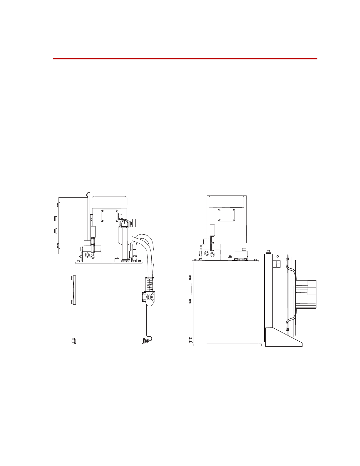
The Model 512.14 Hydraulic Power Unit (HPU) provides high-pressure
hydraulic fluid for test system operation. This compact hydraulic power unit is
designed for use with low force testing systems. The HPU is available with a
water–cooled or an air–cooled heat exchanger.
This section contains the functional description and specifications of the HPU
(also called a hydraulic power supply, or pump).
Functional Description 8
Specifications 10
Dimensions 11
Water Cooled Air Cooled
Model 512.14 Hydraulic Power Unit
512.14 Hydraulic Power Unit Introduction
5
Page 6
Component Identification
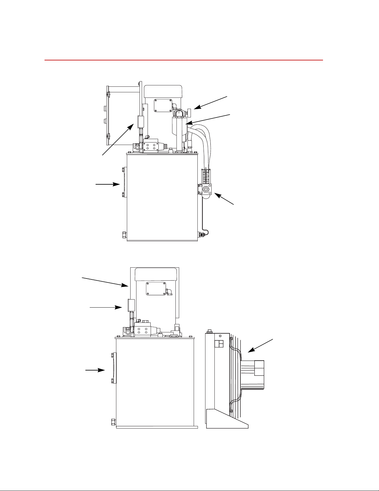
Component Identification
Water-Cool ed
Pressure Gage
Sight Glass
Control Box
Pump Motor
Reservoir
Air-Cooled
Filter Change Gage
Filter
Heat Exchanger
Control Box
Pressure Gage
Sight Glass
Pump Motor
Heat Exchanger (Detached)
Reservoir
Major Components (Side View)
6
Introduction
512.14 Hydraulic Power Unit
Page 7

Component Descriptions
Component Description
Component Identification
Control Box
Pressure Gage
Sight Glass
Reservoir
Heat Exchanger
Filter
Low Fluid and
Overtemperature Sensor
Filter Change Gage
Houses the electronic controls of the pump, including the Stop button, and
Low/High switch. It also houses the thermal overloads to protect the pump
motor. See “Resetting the Thermal Overloads” on page 24.
Shows the current output pressure from the hydraulic power unit. The output
pressure is factory set to 21MPa (3000 psi). See “Adjusting the Output
Pressure” on page 25 to change the output pressure.
Combines a thermometer with a sight glass. You can quickly check the
hydraulic fluid’s temperature, level, and condition (by its color).
Stores the hydraulic fluid. The reservoir has a 57 L (15 gal) capacity. It
includes a magnetic drain plug to help catch metal particles.
Cools the hydraulic fluid. The heat exchanger can be either water-cooled or aircooled. See “Adjusting the Air Flow” on page 22 and “Adjusting the Water
Flow” on page 23 for more information.
Provides 3–micron filtration to fluid returning to the reservoir (see “Replacing
the Filter” on page 31).
(Not shown) Shuts the pump off if fluid gets too low or becomes hotter than
75ºC (160ºF). See “Reducing the Fluid Temperature” on page 21 or “Adding
Hydraulic Fluid” on page 35 for more information.
Shows when it’s time to change the hydraulic filter. The gage is marked with
three zones; green, yellow, and blue.
Pump Motor
Green—The filter is good to use.
Yellow—Change the filter soon.
Red—Do not run the HPU until you have replaced the hydraulic filter element.
Drives a fixed displacement gear pump.
Pumps a 12.5 lpm output at 21 MPa (3.3 gpm at 3000 psi) @ 50 Hz.
Pumps a 15.1 lpm output at 21 MPa (4 gpm at 3000 psi) @ 60 Hz.
512.14 Hydraulic Power Unit Introduction
7
Page 8

Functional Description
Functional Description
The hydraulic power unit (HPU) is the mechanical source of high-pressure
hydraulic fluid required to operate the hydraulic components of a test system. See
“Component Identification” on page 6 for more information about the
components discussed in this section.
Pump A motor drives a hydraulic pump which draws hydraulic fluid from a reservoir
and pressurizes it to 21 MPa (3000 psi). The pressurized fluid is made available
to the hydraulic components in your test system.
Pressure The HPU can produce low and high pressure outputs:
• The low pressure output is approximately 1.4 MPa (200 psi). Low pressure
is normally used while installing a specimen.
• The high pressure can be adjusted to 21 MPa (3000 psi) or less. High
pressure is used for an actual test. When operating in high pressure, the lowpressure vent is blocked.
Filtering The filtration system protects against silting by cleaning the hydraulic fluid to an
ISO particle count of 16/13/9 or better. The filter change gage indicates when the
filter needs to be replaced.
A suction strainer protects the pump from larger particles when the fluid is
pumped from the reservoir. It is located in the bottom of the hydraulic fluid
reservoir.
Heat exchanger Hydraulic fluid temperature is maintained with a heat exchanger that cools the
fluid. The heat exchanger helps keep the temperature of the hydraulic fluid
between 64–68°C (147–155°F). The temperature of the fluid is monitored by an
overtemperature switch. If the fluid temperature exceeds 75ºC (170ºF), a switch
opens and shuts down the HPU. The system cannot be restarted until the fluid
cools. There are two kinds of heat exchangers:
• The water-cooled heat exchanger cools the hydraulic fluid as it passes over
water-filled tubes. A regulating valve can adjust the flow of water through
the tubes, and this affects the amount of cooling the heat exchanger can
accomplish.
• The air-cooled heat exchanger cools the hydraulic fluid as it passes through
a radiator. A fan blows air through the radiator to transfer heat from the
radiator to the air. Louvers control the airflow over the hydraulic radiator,
and this affects the amount of cooling the heat exchanger can accomplish.
Note For additional information, see the Heat Exchanger Care and Water
Quality Guide (MTS part number 015-164-000).
8
Introduction
512.14 Hydraulic Power Unit
Page 9
Functional Description
Electronics The HPU has basic controls to turn it on to low pressure or high pressure and to
turn it off. The HPU includes an Emergency Stop switch that is connected to the
interlock chain of your test system.
A hydraulic interlock can be generated by the hydraulic power supply if one of
the following occurs:
• Low hydraulic fluid level
• High hydraulic fluid temperature
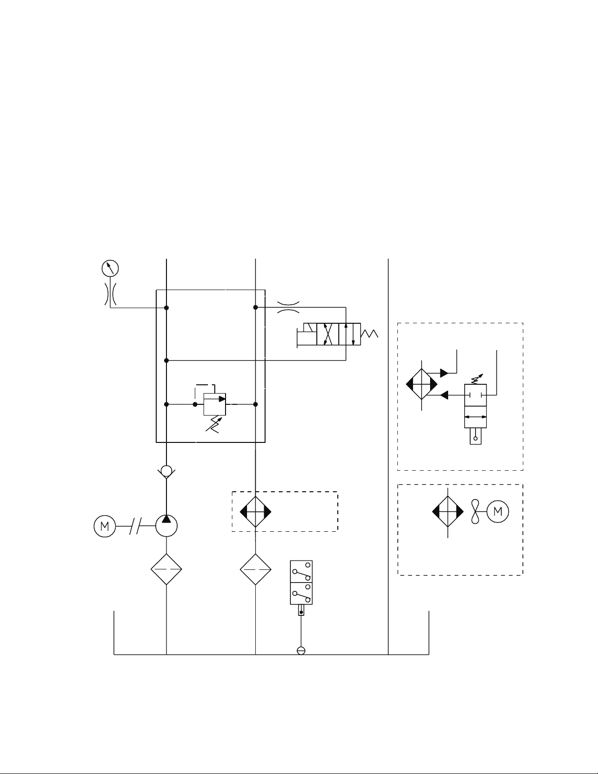
Hydraulic schematic The hydraulic schematic shows how the hydraulic components are connected in
the Model 512.14 Hydraulic Power Unit. Both types of heat exchangers are
shown.
Pressure
Gage
Pressure
Motor
Pressure -8
37° JIC Flare
Relief
Valve
0.714 MPa
(1002000 psi)
Check
Valve
Pump
Return -8
37° JIC Flare
0.125
See Heat
Exchangers
High/Low
Pressure
Solenoid
Drain -06
SAE
Water Out
1/2 ID Hose
Water-Cooled
Heat Exchanger
Fan and Motor
Water In
1/2 ID Hose
1/2 NPT
Strainer
Reservior
512.14 Hydraulic Power Unit Introduction
Filter
Overtemperature
Switch
Low Fluid
Switch
Air-Cooled
Heat Exchanger
9
Page 10

Specifications
Specifications
Environmental
Parameter Specification
Operating temperature
(ambient air)
Heat load
Noise rating† at 1 m
Pump
Flow capacity
Motor rating
Operating voltage
Hydraulic fluid
Nominal temperature
Filtration (microns)
Reservoir capacity
Maximum pressure
Heat exchanger
18–40°C (65–104°F)
*
1061 kcal/hr (4200 BTU/hr)
74 dB (A)
12.5 lpm (3.3 gpm) @ 50 Hz
15.1 lpm (4 gpm) @ 60 Hz
5.6 kW (7.5 hp)
208 V (AC) @ 24.2 A, 3 phase
230 V (AC) @ 22.0 A, 3 phase
460 V (AC) @ 11.0 A, 3 phase
Mobil DTE 25
63°C (145°F)
3 microns absolute
57 liters (15 gallons)
20.7 MPa (3000 psi)
Water cooled or air cooled
®
or Shell Tellus® 46 AW
10
Introduction
Flow requirements
Water pressure
(differential)
Max input pressure
Cooling
Water hose
Hydraulic connections
Pressure
Return
Drain
Weight 115 kg (250 lb)
*
Specification is for 60 Hz operation.
†
Free field value [74 db. Your readings may be up to 10 db (A) more.
13 lpm @ 21°C (3.5 gpm @ 70°F)
0.2 MPa (30 psi)
1 MPa (150 psi)
4892 Kcal/hr (19,410 BTU/hr)
12.7 mm (0.5 in)—inside diameter
each requires a 37° flare
-8
-8
-6
512.14 Hydraulic Power Unit
Page 11
Dimensions
Dimensions
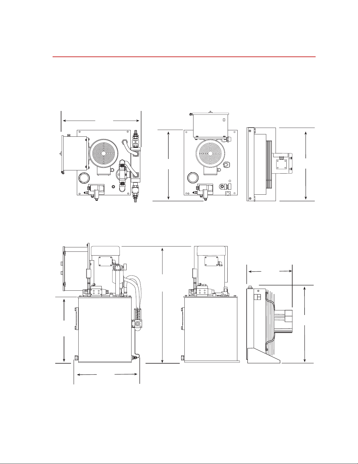
The following figure shows those dimensions which are useful when installing the
hydraulic power unit.
Water Cooled
610 mm
(24 in)
610 mm
(24 in)
Air Cooled
671 mm
(26.4 in)
406 mm
(16 in)
335 mm
(13.2 in)
864 mm
(34 in)
559 mm
(22 in)
508 mm
(20 in)
512.14 Hydraulic Power Unit Introduction
11
Page 12

Dimensions
12
Introduction
512.14 Hydraulic Power Unit
Page 13
Installation
This section describes how to install a Model 512.14 Hydraulic Power Unit.
Note The HPU is designed for indoor use. The HPU should be stored and
installed indoors.
1. Position the hydraulic power unit.
Determine where to put the HPU. Since it is connected to the other
hydraulic equipment through hydraulic lines, the HPU can be located
remotely. Considerations include:
• The air cooled HPU must be located where adequate air movement for
cooling can occur.
• The water cooled HPU requires a source of water.
• The HPU can be moved by a forklift, pallet jack or dolly.
• The HPU produces 74 dB of sound pressure level in a free field acoustic
environment.
• The base of the HPU has four holes that may be used to secure the unit in
place.
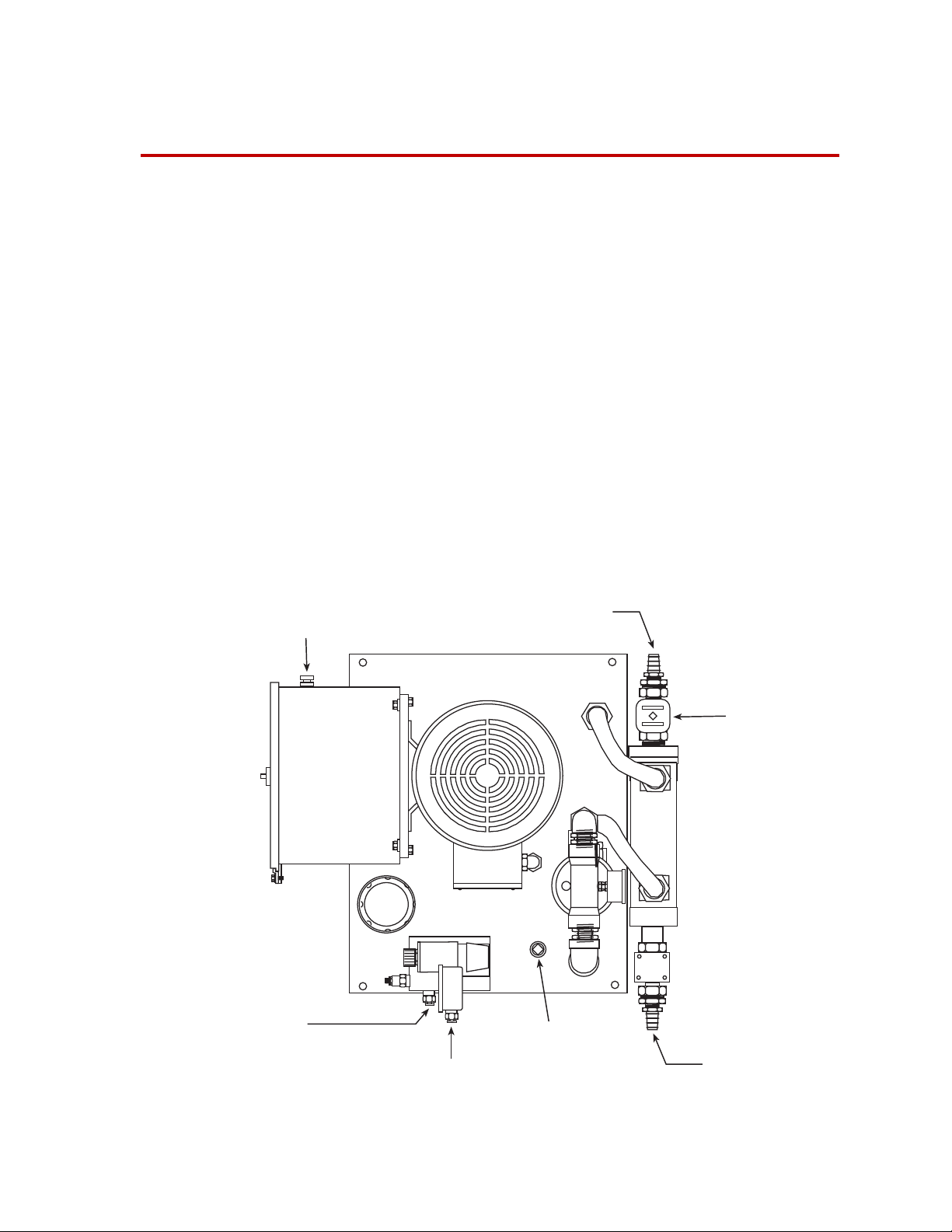
Emergency Stop
Connection
Return Line Connection
Cooling Water In
Water Valve
Drain Line Connection
Pressure Line Connection
Connection Locations (Top View)
512.14 Hydraulic Power Unit Installation
Cooling Water Out
13
Page 14

2. Connect the hydraulic lines.
See “Connection Locations (Top View)” on page 13 to determine the
locations of the hydraulic connections to the HPU. The following table lists
the size of each hydraulic connection.
Connector Size
Pressure, 37º flare -8
Return, 37º flare -8
Drain, 37º flare -6
3. Connect the water lines to the heat exchanger.
Note This applies only to the water-cooled version of the HPU.
The HPU requires connection to a suitable water supply, equipped with an
appropriate shutoff valve, to cool the hydraulic fluid. The differential
pressure required between the HPU water inlet and outlet connections is 0.2
MPa (30 psi). The maximum allowable water inlet pressure is 1 MPa (150
psi).
The water supply must be capable of maintaining the water flow rate given
in the table, “Specifications” on page 10.
See “Connection Locations (Top View)” on page 13 to determine the
locations of the water connections.
4. Connect an external Emergency Stop switch.
An optional Emergency Stop switch can be connected to the 14–pin CPC
connector located on the control box. Before you can use this connector,
remove the jumper from pins 1 and 3 located on the terminal block in the
control box (see “Electrical Schematic” on page 15).
5. Connect the electrical service to the HPU.
Note Electrical connections must be made by qualified personnel and conform
to local codes and regulations. Local electrical codes supersede any
information found here.
A. Open the control box.
B. Open a knock-out hole.
C. Install a wire grommet.
D. Feed the line through the grommet into the control box.
E. Connect the power source lines (L1–L3) to the terminal blocks
according to the required line voltage. See “Electrical Schematic” on
page 15.
14
Installation
F. Connect the ground to the lug identified with a sticker showing the
ground symbol.
512.14 Hydraulic Power Unit
Page 15

Three Phase
L1
L2
L3
Remove Jumper if
Remote Emergency Stop
Switch Connected
1
1 A
3
8
9
1 FU
H1
X1
115 V (ac)
H4
X2
Varistor
Remote
Emergency
Stop Switch
CPC-14S
Stop Switch
Pressure
Start Switch
Low
High
Pressure
SS1
M1
TAS
T-1 Below
77° C (170° F)
Electrical Schematic
1M
FS
Low Fluid
Switch
(opens at
70% full)
Varistor
SOV
OL
Fan and Motor
(air-cooled only)
512.14 Hydraulic Power Unit Installation
15
Page 16

16
Installation
512.14 Hydraulic Power Unit
Page 17

Operation
Contents Running the HPU 18
This section describes the front panel controls and indicators, and provides
operating instructions for the Series 505 Hydraulic Power Unit (HPU).
Recovering From an Interlock Condition 20
Reducing the Fluid Temperature 21
Adjusting the Air Flow 22
Adjusting the Water Flow 23
Resetting the Thermal Overloads 24
Adjusting the Output Pressure 25
512.14 Hydraulic Power Unit Operation
17
Page 18

Running the HPU
Running the HPU
The following procedure is a guideline, and it assumes you are starting the
hydraulic power unit (HPU) after the it has been turned off for some time (the
hydraulic fluid is considered cool). You may want to incorporate portions of this
procedure into your system startup sequence.
1. Check the fluid level in the sight gage.
The hydraulic fluid should be close to the top of the sight glass. If you need
to add fluid, add 1 liter (1 quart) at a time.
Normal Fluid
Level
Low Fluid
Level
Check the Fluid Level
2. At your test controller, make sure hydraulic pressure is turned off.
Note Some controllers can remotely control the HPU.
3. Turn the start switch to LOW PRESS and wait for the motor to get up to
speed.
Turn this switch to HIGH PRESS.
LOW
PRESS.
START
HIGH
PRESS.
PRESS.
LOW
START
HIGH
PRESS.
18
Operation
4. Check to make sure the filter change gage’s needle stays in the green zone.
Turn the HPU off and change its filter if the needle stays in the yellow or red
zones.
Note Cold fluid may push it temporarily into the red zone.
512.14 Hydraulic Power Unit
Page 19

Running the HPU
CAUTION
Do not run the HPU if the filter gage is in the red region.
When the gage needle stays in the red zone, some hydraulic fluid is
bypassing the filter. This unfiltered fluid can wear or damage hydraulic
components.
Turn the HPU off when the filter gage reaches the red zone and change the filter.
Yellow Zone
(warning to change)
Green Zone
(normal)
Red Zone
(do not operate)
Check the Filter Change Gage
5. Check the output pressure gage for the correct output pressure. The pressure
is factory set for 21 MPa (3000 psi).
6. Run the HPU for 20–30 minutes to get the hydraulic fluid up to operating
temperature of 64–68°C (147–155°F).
Once the hydraulic fluid is up to the operating temperature, you can use the
hydraulic system.
7. To turn the HPU off, switch to LOW PRESS, then press the STOP switch.
STOP
In the event of an emergency, press the STOP switch or the optional
Emergency Stop switch.
8. If your HPU is water cooled, make sure the heat exchanger’s water valves
are closed.
512.14 Hydraulic Power Unit Operation
19
Page 20

Recovering From an Interlock Condition
Recovering From an Interlock Condition
Abnormal shutdowns Any one of the following conditions can cause your HPU to suddenly shut down.
You will not be able to restart your HPU until you correct the condition.
Interlock Conditions
Problem Solution
The hydraulic fluid exceeds 75ºC (160ºF). See “Reducing the Fluid
Temperature”
on page 21.
The hydraulic fluid cannot be seen in the sight glass (or it is
at a low level).
A tripped thermal overload or blown fuse in the control
box removed power from the unit.
See “Adding Hydraulic Fluid”
page 35
.
See “Resetting the Thermal
Overloads”
on page 24.
on
20
Operation
512.14 Hydraulic Power Unit
Page 21

Reducing the Fluid Temperature
Reducing the Fluid Temperature
The hydraulic power unit (HPU) will be shut down if the hydraulic fluid reaches
a temperature of 77°C (170° F).
77ºC
(170ºF)
Note The thermometer is for reference only. Use a calibrated thermometer
submersed in the reservoir for an accurate reading.
To reduce the fluid temperature, you need to make adjustments to the heat
exchanger.
• If you have the air-cooled version go to “Adjusting the Air Flow” on page
22.
• If you have the water-cooled version go to “Adjusting the Water Flow” on
page 23.
512.14 Hydraulic Power Unit Operation
21
Page 22

Reducing the Fluid Temperature
Adjusting the Air Flow
Air-cooled heat exchangers use louvers to control airflow through the exchanger.
You may have to adjust them to keep the fluid’s temperature between 64 and 68ºC
(147 and 155ºF).
Adjust
Adjust the Louvers
Make sure the louvers are fully open.
1. Turn the start switch to LOW PRESS and
hold it there to override the shutdown.
If overheated fluid caused the shutdown,
the HPU will now start to run.
PRESS.
LOW
START
HIGH
PRESS.
Keep holding the start switch to LOW
PRESS until the HPU stays running when
you let go of this switch. (It can take up to
hold
two hours for the fluid to cool down if you
do not run the HPU.)
If the HPU still does not run, some other
condition has caused the shutdown.
2. Set the HPU’s output to HIGH PRESS. Put the HPU in a no-flow condition
(no fluid flowing to other hydraulic equipment).
3. Let the HPU run for 15 minutes to stabilize the fluid temperature. Check the
fluid temperature in the sight glass.
• If the temperature is between 64 and 68ºC (147 and 155ºF), stop.
22
Operation
• If not, open or close the louvers as needed and repeat this step.
512.14 Hydraulic Power Unit
Page 23

Adjusting the Water Flow
On water-cooled heat exchangers, the water control valve regulates the flow of
water through the exchanger. MTS sets this valve to keep the hydraulic fluid
temperature between 64 and 68ºC (147 and 155ºF).
An out-of-adjustment water control valve can cause rapid overheating.
Check the Heat Exchanger
Changes in your water supply’s temperature may require adjustment of this
valve.
Reducing the Fluid Temperature
Water Valve
1. Start with the hydraulic fluid at room temperature. Make sure the heat
exchanger’s water supply valves are open.
2. Turn the start switch to LOW PRESS. Then turn the switch to HIGH
PRESS.
Put the HPU into a no-flow condition (where no fluid is flowing to other
hydraulic equipment).
3. Run the HPU for approximately 15 minutes to stabilize the temperature.
Check the fluid temperature in the sight glass.
• If the temperature is between 64 and 68ºC (147 and 155ºF), stop.
• If the temperature is
outside the operating
temperature range, turn
the valve’s screw to raise
Decrease
Increase
or lower the water
temperature and repeat
this step. (Do not turn the
1/2 Turn Maximum
valve screw more than 1/2
turn at a time).
–Adjust the valve screw clockwise to decrease the reservoir
temperature.
–Adjust the valve screw counterclockwise to increase the reservoir
temperature.
512.14 Hydraulic Power Unit Operation
23
Page 24

Resetting the Thermal Overloads
Resetting the Thermal Overloads
The thermal overloads of the hydraulic power unit (HPU) can be tripped by the
following conditions:
• Poor motor ventilation
• The output pressure is set too high
• A pump or motor is seizing
The thermal overloads are located in the control box.
CAUTION
Do not open the control box unless the line voltage is turned off. When
power is present in the control box, high voltage and amperages are also
present.
You can be electrocuted if you touch the wrong component in the control
box.
Disconnect the HPU from power before opening the control box.
1. Check the thermal overloads of the power source to the HPU.
• If it has tripped, reset it and try restarting the HPU.
• If the thermal overloads have not
tripped, remove power from the
Inside Control Box
HPU before opening the control
panel.
Tripped
Indicator
2. Unscrew the clamps holding the
control panel’s door shut.
Reset
3. Check the thermal overloads tripped
Button
indicator. If it has tripped, press
RESET on the overload.
4. Check for a blown fuse. The
replacement fuse must have the same
rating as the blown fuse.
Thermal
Overloads
Fuse
5. Shut the control box door. Use the
clamps to hold it in place.
24
Operation
6. Reconnect the HPU to its electrical power source.
7. Restart the HPU. If the HPU will not restart or shuts down right away, call
MTS.
512.14 Hydraulic Power Unit
Page 25

Adjusting the Output Pressure
The HPU comes with its output pressure set at 21 MPa (3000 psi). Special testing
needs may require you to lower this pressure.
Output Pressure
Adjustment
Adjusting the Output Pressure
CAUTION
Do not set the output pressure higher than 21 MPa (3000 psi).
Setting the output pressure above 21 MPa (3,000 psi) can damage the pump
and its motor.
Set the output pressure no higher than 21 MPa (3000 psi).
Procedure To adjust the output pressure:
1. Set the HPU’s output to HIGH PRESS. Put the HPU into a no-flow
condition (where no fluid is flowing to other hydraulic equipment).
2. Wait for the fluid to reach the operating temperature of 64 and 68ºC (147
and 155ºF).
3. Hold the setscrew with a 5/32–inch hex key. Loosen the locknut with a 9/
16–inch wrench.
512.14 Hydraulic Power Unit Operation
25
Page 26

Adjusting the Output Pressure
Pressure Gage
Locknut
Setscrew
4. Turn the setscrew while watching the gage until you get the output pressure
you want.
5. Hold the setscrew and tighten down the locknut.
26
Operation
512.14 Hydraulic Power Unit
Page 27

Maintenance
Contents Checking the Hydraulic Fluid 29
This section describes preventive maintenance requirements and their
recommended intervals for the Product Name.
Replacing the Filter 31
Sampling the Hydraulic Fluid 32
Adding Hydraulic Fluid 35
Replacing the Hydraulic Fluid 36
Lubricating the Motor 39
Scheduling
maintenance
What to Do When to Do It How to Do It
Make daily visual
inspections
Check fluid quality and
condition
Check functionality of
warning and interlock
devices
The following table lists the recommended interval for each maintenance
procedure.
Maintenance Schedule (part 1 of 2)
Before the start of each day’s
testing.
Every 40 hours or 1 week. Compare the condition of the fluid to that of
Every 40 hours or 1 week. Depress emergency stop button(s) to verify
Check the fluid level in the sight gage and
replenish as required.
Look for signs of fluid leakage.
Check status of dirty filter indicator and
replace filter if required.
Check system operating pressure and adjust
as required.
your sample, including odor and color.
Perform “Checking the Hydraulic Fluid” on
page 29.
that warning and interlock devices are
functioning properly.
Conduct external
inspection of the heat
exchanger
Inspect hydraulic hoses,
replace as required
Replace fluid filter
512.14 Hydraulic Power Unit Maintenance
*
Every 500 hours or 3 months. Look for dents, bulges, and leaks, damaged
gaskets, corrosion, and worn, frayed, or
leaking hoses.
Every 1000 hours or 6 months Look for signs of wear, check for fluid leaks,
tighten connections as needed.
Every 1000 hours or 6 months, or
when the filter gage needle stays
in the yellow or red zone; and
whenever you replace the
hydraulic fluid.
Perform “Replacing the Filter” on page 31.
27
Page 28

Maintenance Schedule (part 2 of 2)
What to Do When to Do It How to Do It
Verify functionality of
HPU interlocks
Lubricate pump motor
Check motor overload
functionality
Verify proper operation of
hydraulic valves
Conduct a hydraulic fluid
analysis
Replace hydraulic fluid
Conduct internal
inspection of heat
exchanger
†
†
†
‡
*,†
Every 1000 hours or 6 months Contact MTS Systems Corporation.
Every 1000 hours or 6 months Perform “Lubricating the Motor” on page 39.
Every 1000 hours or 6 months Contact MTS Systems Corporation.
Every 1000 hours or 6 months Contact MTS Systems Corporation.
Every 6 months or sooner if duty
is severe
‡
.
Obtain a sample and submit it for analysis.
Most oil or other qualified companies can
analyze hydraulic fluid or consult MTS
Systems Corporation.
Perform “Sampling the Hydraulic Fluid” on
page 32.
Every 6 months or sooner if fluid
analysis is not to specifications.
Perform “Replacing the Hydraulic Fluid” on
page 36.
Yearly, or every 2000 hours Look for signs of fouling or corrosion,
conduct chemical or mechanical internal
cleaning as inspection warrants.
Consult the Heat Exchanger Care Guide for
more information.
Check case drain flow of
hydraulic pump
Replace heat exchanger
Yearly, or every 2000 hours Contact MTS Systems Corporation.
†
Every 3 years or 5,000 hours Replace as inspection warrants. Contact MTS
Systems Corporation for special training.
†
Replace motor bearings
Replace hydraulic hoses,
motors, pumps
†
Every 3 years or 5,000 hours Contact MTS Systems Corporation.
Every 5 years or 10,000 hours Replace as inspection warrants. Hydraulic
pumps may be rebuilt or replaced as required
by inspection. Motors may be rewound or
replaced as required by inspection. Contact
MTS Systems Corporation for special
training.
*See the MTS Heat Exchanger Care Guide (part number 015-164-000).
† Special training required. Contact MTS Systems Corporation.
‡See the MTS Fluid Care Guide (part number 050-000-536).
Spare parts Parts that are specified in the maintenance procedures of this section can be
obtained from MTS Systems Corporation. See “Contact information” on the back
of the title page to order spare parts.
28
Maintenance
512.14 Hydraulic Power Unit
Page 29

Checking the Hydraulic Fluid
Hydraulic fluid contamination and deterioration normally occur in most
hydraulic systems. Failure to keep your fluid sufficiently free of contaminants or
to change the fluid before severe fluid breakdown occurs will cause poor system
performance and may lead to expensive system cleanups. Servovalves are
especially susceptible to damage from dirty hydraulic fluid.
To avoid these problems, you must maintain a clean hydraulic system. Regularly
test samples of your hydraulic fluid and follow the recommended maintenance
procedures described here. For more information on hydraulic fluid care, refer to
the MTS Hydraulic Fluid Care Guide.
Important To prevent problems with inconsistent and inferior fluids, MTS
recommends only Mobil DTE 25 or Shell Tellus 46 to its
customers.
Procedure Perform the following visual and olfactory checks of the hydraulic fluid's
condition weekly. If you suspect contamination of the hydraulic fluid, take a
sample and have it analyzed.
Checking the Hydraulic Fluid
1. Check the fluid level in the HPU sight gage to verify the fluid level is
correct.
• A low level can indicate a leak. If necessary, add enough fluid to bring
the reservoir level up to the proper operating level.
• A high level can indicate water contamination from the heat exchanger.
2. Check the hydraulic fluid color. Clean hydraulic fluid is amber in color.
Keep a sample of brand-new hydraulic fluid in a clean glass container for
comparison. A change in color can mean that the fluid is contaminated or
that it has broken down chemically. Refer to the table, “Appearance of
Hydraulic Fluid Sample,” on page 33 if the hydraulic fluid appears different
than the clean sample.
3. Check the smell of the hydraulic fluid. Burnt-smelling hydraulic fluid can
indicate a chemical breakdown.
If you detect a distinct change in the smell of hydraulic fluid, have it
chemically analyzed by the manufacturer.
4. Keep records of the maximum reservoir temperature.
High operating temperatures can cause the fluid to break down. If your
records indicate a pattern of overheating, consult your MTS Field Service
Engineer to determine if changes or adjustments to your hydraulic system
are required.
512.14 Hydraulic Power Unit Maintenance
29
Page 30

Checking the Hydraulic Fluid
5. Check and adjust the hydraulic fluid delivery system so that:
• Hydraulic fluid temperature stabilizes within the parameters given in
“Specifications” on page 10 when the HPU is operating at high
pressure.
If you need to adjust the water-regulating valve, refer to “Adjusting the
Wate r F low” on page 23.
• Pressure line reading is maintained at 21 MPa (3000 psi) maximum
static value.
If you need to adjust the pressure control valves, refer to “Adjusting the
Output Pressure” on page 25.
• Maximum drain line back pressure is limited to 0.1 MPa (15 psi).
Other system adjustments are described in the Operation chapter.
30
Maintenance
512.14 Hydraulic Power Unit
Page 31

Replacing the Filter
The filter element of the HPU should be replaced for the following reasons:
• When the filter change gage’s needle stays in the yellow or red zone with the
hydraulic fluid at operating temperature
• Whenever the hydraulic fluid is changed
• The filter manufacturer’s recommended maximum interval has passed
(1000 hours or 6 months)
Prerequisite You will need an oil filter wrench and a 3–micron oil filter (MTS part number
119515-21).
Procedure Perform the following procedure to change the filter element.
1. Press STOP to turn off the HPU.
2. Check the output pressure gage. Ensure that the pressure is at zero before
proceeding.
Replacing the Filter
3. Use an oil filter wrench to loosen the old filter. Screw the filter
counterclockwise to remove it.
Change Filter when
needle stays in
yellow or red zone
CCW
4. Wet the new filter’s gasket with clean hydraulic fluid.
5. Screw the filter clockwise to install it. Turn the new filter until the gasket
touches its sealing surface, then hand tighten the filter 1/2 turn.
Note Tightening the filter with a wrench will not make it seal better, but it will
make it more difficult to remove.
6. Start the pump in low to purge the air from the hydraulic lines and
components.
7. Set the HPU’s output to HIGH PRESS. Let the HPU run a few minutes and
check for leaks.
512.14 Hydraulic Power Unit Maintenance
31
Page 32

Sampling the Hydraulic Fluid
Sampling the Hydraulic Fluid
This section describes how to check the quality of the hydraulic fluid. Review the
following hints before obtaining your sample:
• Avoid contamination.
– Keep the sample bottle in the storage box of the hydraulic fluid
sampling kit until it is needed.
– Do not remove the cap from the bottle until immediately before taking
the sample.
– Do not set the cap down on a dirty surface or in an area where airborne
dust can settle.
• For additional information on hydraulic fluid care, see the Hydraulic Fluid
Care Guide (part number 050-000-536) found in the documentation package
inside the electrical control box.
• Hold the hose valve assembly still when taking a sample.
• Do not let the hose sample assembly line touch the mouth of the bottle or go
into the bottle.
Prerequisite You will need a hydraulic fluid sampling kit (part number 055-589-601) and a
fluid analysis kit (MTS part number 011-860-301) or a clean, 180 ml sample
bottle.
Adapter
Needle Valve
Hose Valve Assembly for Fluid Sampling
Procedure Take a fluid sample from the reservoir to get a visual indication of the fluid level
and relative contamination. Clean hydraulic fluid is clear and has an amber color.
If the composition of the fluid appears to have changed, obtain a sample of the
hydraulic fluid from the sample port and check the fluid qualities.
1. Operate the HPU until the hydraulic fluid is at normal operating temperature
(about 30 minutes).
2. Close the needle valve. Connect the hose valve assembly to the sample port
located on the hydraulic manifold.
32
Maintenance
3. Open the needle valve on the hose valve assembly and flush 1 liter (1 quart)
of hydraulic fluid though the sampling assembly. This fluid can be directed
to a waste container or back into the HPU reservoir.
512.14 Hydraulic Power Unit
Page 33

Sampling the Hydraulic Fluid
4. Obtain a sample of the hydraulic fluid after flushing the valve hose
assembly.
A. Without closing the valve, quickly place the sample bottle into the fluid
stream (keep the sample bottle sealed until the sample is to be taken).
B. Fill the sample bottle (175 mL/6 oz) with fluid.
C. Close the valve on the hose valve assembly and cap the sample bottle.
5. Check the fluid qualities of the sample by comparing it to a small jar of
clean hydraulic fluid. Clean hydraulic fluid has an amber color. The table,
Appearance of Hydraulic Fluid Sample, below indicates unacceptable fluid
qualities.
6. If there still is any uncertainty regarding fluid quality, obtain another sample
of the fluid and have it analyzed. The fluid tests should include chemical
analysis, particle count, and viscosity checks. Most oil companies have
facilities for performing these tests, or consult MTS Systems Corporation.
7. Close the needle valve and remove the hose and valve assembly. Open the
needle valve.
Appearance of Hydraulic Fluid Sample (part 1 of 2)
Fluid Properties Problem What to Do
Dark colored fluid
Indicates chemical breakdown or
the hydraulic fluid has been allowed
Analyze the fluid and replace as
required by the analysis.
to rise above the maximum
recommended temperature (severe
overheating)
If the cause was overheating, flush the
entire system to remove varnish or
residue. Consult your MTS Field
Service Engineer to determine if
changes or adjustments to your
hydraulic system are required.
Burnt odor
Indicates chemical breakdown or
the hydraulic fluid has been allowed
to rise above the maximum
recommended temperature (severe
overheating)
Analyze the fluid and replace as
required by the analysis.
If the cause was overheating, flush the
entire system to remove varnish or
residue. Consult your MTS Field
Service Engineer to determine if
changes or adjustments to your
hydraulic system are required.
Opaque fluid
Indicates chemical breakdown Replace the fluid
512.14 Hydraulic Power Unit Maintenance
33
Page 34

Sampling the Hydraulic Fluid
Fluid Properties Problem What to Do
Appearance of Hydraulic Fluid Sample (part 2 of 2)
Milky appearance
Sediment at the bottom of
the sample container (after
sample has stood
overnight)
Indicates water is present in the
fluid
Indicates collapsed, ruptured, or
clogged filter(s)
Check the heat exchanger for damage.
Look for other water sources if the
water does not appear to be coming
from the heat exchanger.
Identify and correct the source of the
water leakage and replace the fluid if
necessary.
Analyze the fluid and replace the filter
element.
Clean the fluid or replace it as required
by the analysis.
34
Maintenance
512.14 Hydraulic Power Unit
Page 35

Adding Hydraulic Fluid
1. The hydraulic power unit (HPU) will shut down when fluid drops below the
sight glass. Normally, it should be close to the top of the sight glass.
No Fluid Visible
Adding Hydraulic Fluid
Normal Level
CAUTION
Check the Fluid Level
Do not mix different brands of hydraulic fluid.
Mixing different brands of hydraulic fluid can contaminate your system.
Call MTS if you’re not sure what brand of hydraulic fluid your system uses.
Note New fluid should be prefiltered with a 10 micron filter since it may not be
clean.
2. Open the filler cap. Add 1 liter (1 quart) of fluid at a time until the fluid level
is normal.
3. Replace the cover cap.
4. Start the HPU.
512.14 Hydraulic Power Unit Maintenance
35
Page 36

Replacing the Hydraulic Fluid
Replacing the Hydraulic Fluid
Replace the hydraulic fluid in the HPU reservoir whenever you have determined
that the hydraulic fluid is no longer suitable for use.
Recommended
equipment:
• A transfer pump with a 10 micron filter (such as the Model 590.01 Fluid
Transfer Pump)
• A 125 kg (250 lb) capacity hoist
• Synasol® or a similar cleaning solvent
• Lint-free cloths or manufactured rags
• A container for the used hydraulic oil and a drain pan that will fit underneath
the drain plug
• A hydraulic fluid sampling kit (MTS part number 055-589-601).
• A new filter (see “Replacing the Filter” on page 31)
Prerequisite Perform the procedure “Sampling the Hydraulic Fluid” on page 32 to determine
if the hydraulic fluid should be replaced.
Identify and correct any sources of contamination.
CAUTION
Mixing different brands of hydraulic fluid can contaminate your system.
Contaminated hydraulic fluid can cause premature wear of the hydraulic
components in your system.
Do not mix different brands of hydraulic fluid. MTS Systems Corporation
recommends using Mobil DTE-25 or Shell Tellus 46 AW hydraulic fluid.
36
Procedure 1. Prepare the HPU.
Maintenance
A. Press STOP to turn off the HPU.
B. Remove electrical power to the HPU via the circuit breaker at the
power source or by unplugging the HPU.
C. Remove the filler cap’s strainer assembly.
512.14 Hydraulic Power Unit
Page 37

Filler Cap
Replacing the Hydraulic Fluid
2. Remove the hydraulic fluid.
A. Remove the transfer pump’s filter (you do not need to filter the dirty
hydraulic fluid when removing it).
B. Use the transfer pump to remove the old hydraulic fluid from the
reservoir.
C. Remove the drain plug to drain any remaining fluid.
D. Drain the hydraulic fluid from hoses and accumulators in the system.
Reservoir Cover
Screws (one each
Stop Switch
Sight Gage
Filter
Hydraulic Fluid Hoses
(to the heat exchanger)
Reservoir
Drain
Component Locations (Top and Side Views)
512.14 Hydraulic Power Unit Maintenance
37
Page 38

Replacing the Hydraulic Fluid
CAUTION
Synasol is toxic and flammable.
Use the Synasol solvent in a ventilated area and keep it away from an open
flame.
Follow the cautions and warnings on its container.
3. Clean the reservoir.
A. Disconnect the heat exchanger’s two hydraulic fluid lines.
B. Unscrew the cover screws attaching the cover plate to the reservoir.
C. Attach straps to the cover plate’s two lifting eyes. Lift the cover plate
clear of the reservoir.
D. Clean the inside of the reservoir using clean cloths dampened with
Synasol. Clean the pump and bottom of the cover plate as well.
E. Inspect the pump’s suction strainer. Replace this strainer if it is plugged
or damaged.
F. Lower the cover plate back down onto the reservoir.
G. Wipe off the magnetic drain plug and install it.
H. Tighten the four screws that attach the cover plate to the reservoir.
4. Add new hydraulic fluid to the reservoir.
A. Close the fluid drain.
A. Install the transfer pump’s 10–micron filter.
B. Pump clean hydraulic fluid into the reservoir. Stop when the fluid level
gets close to the top of the sight glass.
C. Install the filler cap’s strainer assembly.
5. Replace the HPU filter (see “Replacing the Filter” on page 31).
6. Run the HPU.
Turn the HPU to LOW PRESS. Run the HPU in a no-flow condition (no
fluid is flowing to other hydraulic equipment) for about one hour to filter the
new hydraulic fluid.
7. Check the filter change gage’s needle. Replace the filter if the needle
remains in the yellow or red zone.
38
Maintenance
512.14 Hydraulic Power Unit
Page 39

Lubricating the Motor
The pump’s motor bearing needs lubrication every six months.
Lubricating the Motor
Grease Fittings
CAUTION
1. Turn off the HPU.
2. Wipe off both grease fittings.
3. Using a grease gun, apply grease to each fitting. MTS recommends Shell
Dolium R. Chevron SRI No. 2, or Texaco Premium RB grease.
Do not overgrease the motor.
Too much grease could short out the motor.
512.14 Hydraulic Power Unit Maintenance
39
Page 40

Lubricating the Motor
40
Maintenance
512.14 Hydraulic Power Unit
Page 41

Page 42

Page 43

Page 44

m
MTS Systems Corporation
14000 Technology Drive
Eden Prairie, Minnesota 55344-2290 USA
Toll Free Phone: 800-328-2255
(within the U.S. or Canada)
Phone: 952-937-4000
(outside the U.S. or Canada)
Fax: 952-937-4515
E-mail: info@mts.com
http://www.mts.com
ISO 9001:2000 Certified QMS
 Loading...