

Page 1

Model 512.04 Hydraulic Power Unit
Product Information
l
015-206-401 C
Page 2

Copyright information
Trademark information
Contact information
Publication information
© 2000 MTS Systems Corporation. All rights reserved.
MTS is a registered trademark of MTS Systems Corporation.
MTS is a registered trademark of MTS Systems Corporation.
DTE is a registered trademark of Mobil Corporation.
Tellus is a registered trademark of Shell Oil Corporation.
Synasol is a registered trademark of Union Carbide Corporation
MTS Systems Corporation
14000 Technology Drive
Eden Prairie, Minnesota 55344-2290 USA
Toll Free Phone: 800-328-2255 (within the U.S. or Canada)
Phone: 952-937-4000 (outside the U.S. or Canada)
Fax: 952-937-4515
E-mail: info@mts.com
http://www.mts.com
ANUAL
M
ART
N
UMBER
P
152064 -01A October 1998
UBLICATION
P
D
ATE
015-206-401 B November 1999
015-206-401 C August 2000
Page 3

Contents
Contents 3
Introduction 5
Functional Description 6
Component Identification 8
Specifications 10
Dimensions 11
Installation 13
Operation 17
Maintenance 21
Reducing the Fluid Temperature 22
Adjusting the Air Flow 23
Adjusting the Water Flow 24
Adding Hydraulic Fluid 25
Resetting the Thermal Overloads 26
Changing the Output Pressure 27
Lubricating the Motor 29
Changing the Filter 30
Changing the Hydraulic Fluid 31
Model 512.04 Hydraulic Power Unit Contents
3
Page 4

4
Contents
Model 512.04 Hydraulic Power Unit
Page 5
Introduction
Contents
Functional Description 6
Component Identification 8
Specifications 10
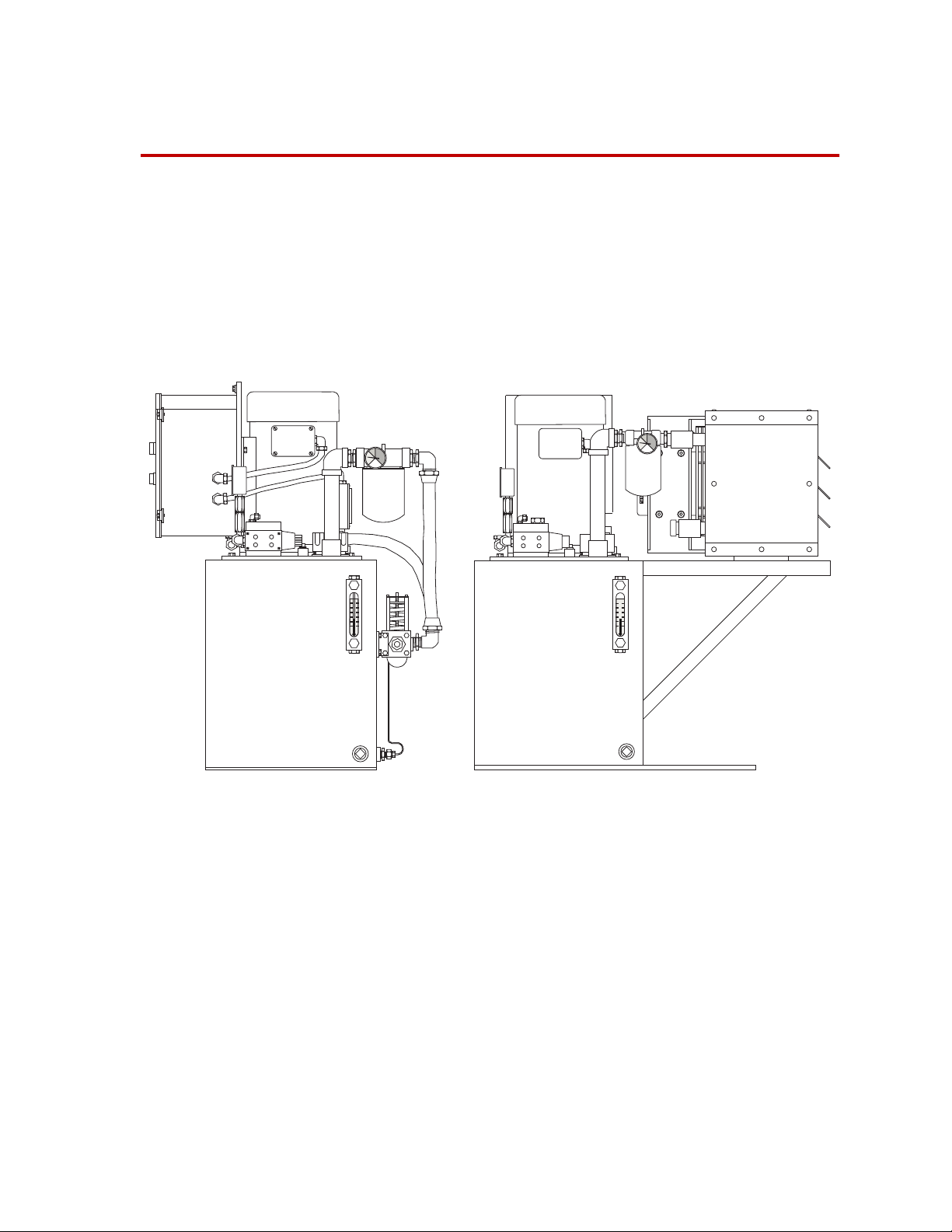
This manual documents the Model 512.04 Hydraulic Power Unit (HPU),
also called a hydraulic power supply (HPS), or pump. This compact
hydraulic power unit is designed for use with low force testing systems.
The HPU is available with a water–cooled or an air–cooled heat exchanger.
Water Cooled Air Cooled
Model 512.04 Hydraulic Power Unit
What you need to
know
Model 512.04 Hydraulic Power Unit Introduction
MTS Systems Corporation assumes that you know how to use your
controller. See the appropriate manual for information about performing
any controller-related step in this manual’s procedures. You are expected
to know how to perform the following procedures
• Using the controller HPU controls in conjunction with the control
located on the HPU
• Controlling hydraulic fluid flow to other hydraulic equipment
5
Page 6

Functional Description
The hydraulic power unit (HPU) is the mechanical source of high-pressure
hydraulic fluid required to operate the hydraulic components of a test
system. See “Component Identification” on page 8 for more information
about the components discussed in this section.
Pump
Pressure
Filtering
Heat exchanger
A motor drives a hydraulic pump which draws hydraulic fluid from a
reservoir and pressurizes it to 13.8 MPa (2000 psi). The pressurized fluid is
made available to the hydraulic components in your test system.
The HPU can produce low and high pressure outputs:
• The low pressure output is approximately 1.4 MPa (200 psi). Low
pressure is normally used while installing a specimen.
• The high pressure can be adjusted to 13.8 MPa (2000 psi) or less. High
pressure is used for an actual test. When operating in high pressure,
the low-pressure vent is blocked.
The filtration system protects against silting by cleaning the hydraulic fluid
to an ISO particle count of 14/11 or better. The filter change gage indicates
when the filter needs to be replaced.
A suction strainer protects the pump from larger particles when the fluid is
pumped from the reservoir. It is located in the bottom of the hydraulic fluid
reservoir.
Hydraulic fluid temperature is maintained with a heat exchanger that cools
the fluid. The heat exchanger helps keep the temperature of the hydraulic
fluid between 64–68°C (147–155°F). The temperature of the fluid is
monitored by an overtemperature switch. If the fluid temperature exceeds
75ºC (170ºF), a switch opens and shuts down the HPU. The system cannot
be restarted until the fluid cools. There are two kinds of heat exchangers:
6
Introduction
• The water-cooled heat exchanger cools the hydraulic fluid as it passes
over water-filled tubes. A regulating valve can adjust the flow of water
through the tubes, and this affects the amount of cooling the heat
exchanger can accomplish.
• The air-cooled heat exchanger cools the hydraulic fluid as it passes
through a radiator. A fan blows air through the radiator to transfer heat
from the radiator to the air. Louvers control the airflow over the
hydraulic radiator, and this affects the amount of cooling the heat
exchanger can accomplish.
Model 512.04 Hydraulic Power Unit
Page 7
Pressure
Gage
Electronics
Hydraulic
schematic
Pressure -8
37° JIC Flare
The HPU has basic controls to turn it on to low pressure or high pressure
and to turn it off. The HPU includes an Emergency Stop switch that is
connected to the interlock chain of your test system.
A hydraulic interlock can be generated by the hydraulic power supply if
one of the following occurs:
• Low hydraulic fluid level
• High hydraulic fluid temperature
• Dirty hydraulic power supply filter (optional)
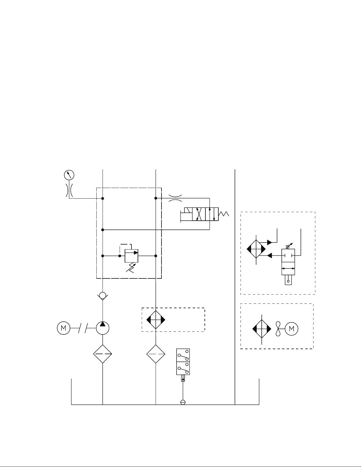
The hydraulic schematic shows how the hydraulic components are
connected in the Model 512.04 Hydraulic Power Unit. Both types of heat
exchangers are shown.
Return -8
37° JIC Flare
0.125
Drain -06
SAE
Motor
Pressure
Relief
Valve
1/2 NPT
Strainer
0.7–14 MPa
(100–2000 psi)
Check
Valve
Pump
Filter
See Heat
Exchangers
Overtemperature
High/Low
Pressure
Solenoid
Switch
Low Fluid
Switch
Water Out
1/2 ID Hose
Water-Cooled
Heat Exchanger
Air-Cooled Heat
Fan and Motor
Water In
1/2 ID Hose
Exchanger
Reservior
Model 512.04 Hydraulic Power Unit Introduction
7
Page 8

Component Identification
This table describes the components shown in the figure on page 9.
Component Descriptions
C
OMPONENT
Control Box
Pressure Gage
Sight Glass
Reservoir
Heat Exchanger
Filter
Low Fluid and
Overtemperature Sensor
Filter Change Gage
D
ESCRIPTION
Houses the electronic controls of the pump, including the Stop button,
Low/High switch, and Reset button. It also houses the thermal
overloads to protect the pump motor. See “Resetting the Thermal
Overloads” on page 26.
Shows the current output pressure from the hydraulic power unit. The
output pressure is factory set to 13.8 MPa (2000 psi). See “Changing the
Output Pressure” on page 27 to change the output pressure.
Combines a thermometer with a sight glass. You can quickly check the
hydraulic fluid’s temperature, level, and condition (by its color).
Stores the hydraulic fluid. The reservoir has a 57 L (15 gal) capacity. It
includes a magnetic drain plug to help catch metal particles.
Cools the hydraulic fluid. The heat exchanger can be either water-cooled
or air-cooled.
Provides 3–micron filtration to fluid returning to the reservoir (see
“Changing the Filter” on page 30).
(Not shown) Shuts the pump off if fluid gets too low or becomes hotter
than 75ºC (160ºF). See “Reducing the Fluid Temperature” on page 22 or
“Adding Hydraulic Fluid” on page 25 for more information.
Shows when it’s time to change the hydraulic filter. The gage is marked
with three zones; green, yellow, and blue.
Pump Motor
Introduction
8
Green—The filter is good to use.
Yellow—Change the filter soon.
Red—Do not run the HPU until you have replaced the hydraulic filter
element.
Drives a fixed displacement gear pump.
Pumps a 12.5 lpm output at 13.8 MPa (3.3 gpm at 2000 psi) @ 50 Hz.
Pumps a 15.1 lpm output at 13.8 MPa (4 gpm at 2000 psi) @ 60 Hz.
Model 512.04 Hydraulic Power Unit
Page 9
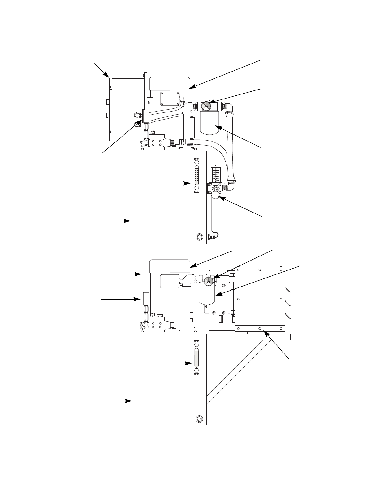
Control Box
Pressure Gage
Sight Glass
Reservoir
Pump Motor
Water-Cooled
Filter Change Gage
Filter
Heat Exchanger
Control Box
Pressure Gage
Sight Glass
Reservoir
Pump Motor Filter Change Gage
Air-Cooled
Filter
Heat Exchanger
Major Components
Model 512.04 Hydraulic Power Unit Introduction
9
Page 10

Specifications
Model 512.04 Specifications
P
ARAMETER
Environmental
Operating temperature
(ambient air)
Heat load
Noise rating
Pump
Flow capacity
at 13.8 MPa (2000 psi)
Motor rating
Operating voltage
Hydraulic fluid
Nominal temperature
Filtration (microns)
Reservoir capacity
*
†
at 1 m
S
PECIFICATION
18–49°C (65–104°F)
1061 kcal/hr (4200 BTU/hr)
74 db (A)
12.5 lpm (3.3 gpm) @ 50 Hz
15.1 lpm (4 gpm) @ 60 Hz
3.7 kW (5.0 hp)
208 V (ac) @ 16.7 A, 3 phase
230 V (ac) @ 15.2 A, 3 phase
460 V (ac) @ 7.6 A, 3 phase
Mobil DTE 26
®
or Shell Tellus
63°C (145°F)
3 µ absolute
57 liters (15 gallons)
®
26
Heat exchanger
Flow requirements
Water pressure
(differential)
Max input pressure
Cooling
Water hose
Hydraulic connections
Pressure
Return
Drain
Weight
*
Specification is for 60 Hz operation.
†
Free field value [75 db (A)
may be up to 10 db (A) more.
Water cooled or air cooled
13 lpm @ 21°C (3.5 gpm @ 70°F)
0.2 MPa (30 psi)
1 MPa (150 psi)
3276 Kcal/hr (13,000 BTU/hr)
12.7 mm (0.5 in)—inside diameter
each requires a 37° flare
-8
-8
-6
115 kg (250 lb)
» heavy traffic at 17 m]. Your readings
10
Introduction
Model 512.04 Hydraulic Power Unit
Page 11
Dimensions
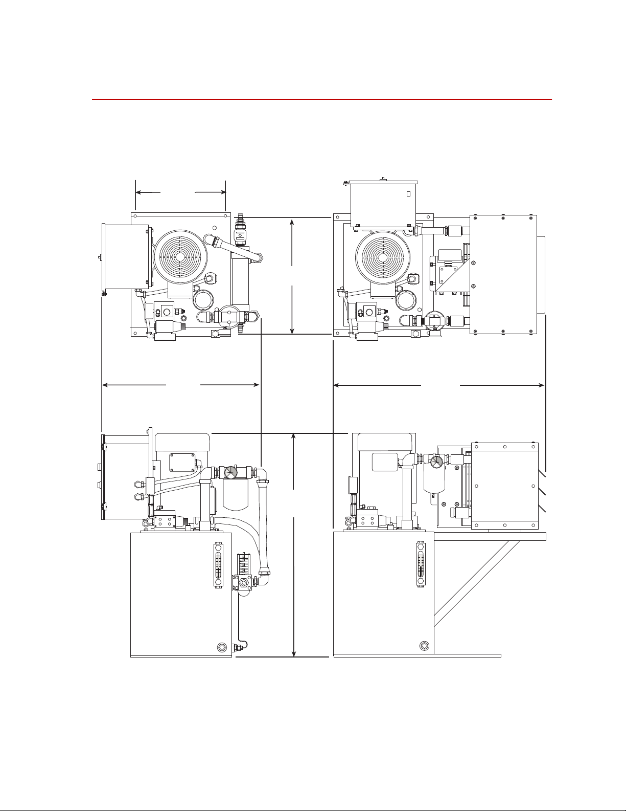
The following figure shows those dimensions which are useful when
installing the hydraulic power unit.
Water Cooled
355 mm
(14 in)
584 mm
(23 in)
Air Cooled
457 mm
(18 in)
787 mm
(31 in)
889 mm
(35 in)
Model 512.04 Hydraulic Power Unit Introduction
11
Page 12

12
Introduction
Model 512.04 Hydraulic Power Unit
Page 13

Installation
Perform the following to install the Model 512.04 Hydraulic Power Unit.
1. Position the hydraulic power unit.
You should determine where to put the hydraulic power unit. Since it
is connected to the other hydraulic equipment through hydraulic lines,
the HPU can be located remotely.
• The air cooled HPU must be located where adequate air
movement for cooling can occur.
• The water cooled HPU requires a source of water.
• The base of the HPU has four holes that may be used to secure
the unit in place.
Emergency Stop Connection
Drain Line Connection
Return Line Connection
Pressure Line Connection
Cooling Water In
Cooling Water Out
Connection Locations
Model 512.04 Hydraulic Power Unit Installation
13
Page 14

2. Connect the hydraulic lines.
See “Connection Locations” on page 13 to determine the locations of
the hydraulic connections to the HPU. See the following table to
identify the size of each hydraulic connection.
Hydraulic Connectors
ONNECTOR
C
Pressure, 37º flare -8
Return, 37º flare -8
Drain, 37º flare -6
IZE
S
3. Connect the water lines to the heat exchanger.
NOTE This only applies to the water-cooled version of the HPU.
See “Connection Locations” on page 13 to determine the locations of
the water connections.
4. Connect an external Emergency Stop switch.
An optional Emergency Stop switch can be connected to the 14–pin
CPC connector located on the control box. Before you can use this
connector, remove the jumper from pins 1 and 3 located on the
terminal block in the control box (see “Electrical Schematic” on page
15).
5. Connect the electrical service to the HPU.
NOTE You may want to have an electrician complete this step. Also, local
electrical codes supersede any information found here.
A. Open the control box.
B. Open a knock-out hole.
C. Install a wire grommet.
D. Feed the line through the grommet into the control box.
E. Connect the power source lines (L1–L3) to the terminal blocks
according to the required line voltage. See “Electrical Schematic”
on page 15.
F. Connect the ground to the lug identified with a sticker showing
the ground symbol.
14
Installation
Model 512.04 Hydraulic Power Unit
Page 15

Three Phase
L1
L2
L3
Remove Jumper if
Remote Emergency Stop
Switch Connected
1
1 A
3
8
9
1 FU
H1
X1
115 V (ac)
X2
Varistor
H4
Remote
Emergency
Stop Switch
CPC-14S
Stop Switch
Pressure
Start Switch
Low
High
Pressure
SS1
M–1
TAS
T-1 Below
77° C (170° F)
Electrical Schematic
1M
FS
Low Fluid
Switch
(opens at
70% full)
Varistor
SOV
OL
Fan and Motor
(air-cooled only)
Model 512.04 Hydraulic Power Unit Installation
15
Page 16

16
Installation
Model 512.04 Hydraulic Power Unit
Page 17

Operation
The following procedure is a guideline, and it assumes you are starting the
hydraulic power unit (HPU) after the it has been turned off for some time
(the hydraulic fluid is considered cool). You may want to incorporate
portions of this procedure into your system startup sequence.
1. Check the fluid level in the sight gage. The hydraulic fluid should be
close to the top of the sight glass. If you need to add fluid, add 1 liter
(1 quart) at a time.
Open
Water
(Out)
Normal Level
No Fluid Visible
Check the Fluid Level
2. If your HPS is water cooled, make sure its heat exchanger’s water
valves are open.
Open
Water
(In)
Open the Exchanger’s Valves
Model 512.04 Hydraulic Power Unit Operation
17
Page 18

3. At your test controller, make sure hydraulic pressure is turned off.
NOTE Some controllers can remotely control the HPU. The Model 512.04
Hydraulic Power Unit does not support this feature.
4. Turn the start switch to START/LOW PRESS. and wait for the motor to
get up to speed.
Turn this switch to HIGH PRESS.
CAUTION
START
LOW
PRESS.
HIGH
PRESS.
START
LOW
PRESS.
HIGH
PRESS.
5. Check to make sure the filter change gage’s needle stays in the green
zone.
NOTE Cold fluid may push it temporarily into the red zone.
Turn the HPU off and change its filter if the needle stays in the yellow
or red zones.
Do not run the HPU if the filter gage is in the red region.
When the gage needle stays in the red zone, some hydraulic fluid is
bypassing the filter. This unfiltered fluid can wear or damage hydraulic
components.
Turn the HPU off when the filter gage reaches the red zone and change the
filter.
18
Operation
Yellow Zone
(warning to change)
Green Zone
(normal)
Red Zone
(do not operate)
Check the Filter Change Gage
6. Check the output pressure gage for the correct output pressure. The
pressure is factory set for 13.8 MPa (2000 psi).
Model 512.04 Hydraulic Power Unit
Page 19

7. Run the HPU for 20–30 minutes to get the hydraulic fluid up to
operating temperature of 64–68°C (147–155°F). Once the hydraulic
fluid is up to the operating temperature, you can use the hydraulic
system.
8. To turn the HPU off, switch to low pressure then press the STOP
switch.
STOP
In the event of an emergency, press the STOP switch or the optional
Emergency Stop switch.
9. If your HPS is water cooled, make sure its heat exchanger’s water
valves are closed.
Model 512.04 Hydraulic Power Unit Operation
19
Page 20

20
Operation
Model 512.04 Hydraulic Power Unit
Page 21

Maintenance
Contents Reducing the Fluid Temperature 22
Adjusting the Air Flow 23
Adjusting the Water Flow 24
Resetting the Thermal Overloads 26
Changing the Output Pressure 27
Lubricating the Motor 29
Changing the Filter 30
Changing the Hydraulic Fluid 31
Maintenance Intervals
W
HAT TO DO WHEN TO DO IT
Recover from an abnormal shutdown As needed–when the HPU suddenly stops running.
Lower the output pressure As required by your test needs.
Adjust the heat exchange louvers When you can not maintain a fluid temperature between 64
and 68ºC (147 and 158ºF).
Adjust the water control valve When you can not maintain a fluid temperature between 64
and 68ºC (147 and 158ºF).
Lubricate the pump motor Every six months.
Change the filter When the filter gage needle stays in the yellow or red zone;
whenever you change hydraulic fluid.
Change the fluid If the fluid’s condition becomes poor, or fluid analysis shows it
is necessary.
Abnormal
shutdowns
Any one of the following can cause your HPU to suddenly shut down. You
will not be able to restart your HPU until you correct the condition.
PROBLEM SOLUTION
The hydraulic fluid exceeds
75ºC (160ºF).
The hydraulic fluid cannot be seen in
the sight glass (or it is at a low level).
A tripped thermal overload or blown
fuse in the control box removed
power from the unit.
See “Reducing the Fluid
Temperature” on page 22.
See “Adding Hydraulic Fluid” on
page 25
See “Resetting the Thermal
Overloads” on page 26.
.
Model 512.04 Hydraulic Power Unit Maintenance
21
Page 22

Reducing the Fluid Temperature
The hydraulic power unit (HPU) will be shut down if the hydraulic fluid
reaches a temperature of 77°C (170° F).
77ºC
(170ºF)
NOTE The thermometer is for reference only. Use a calibrated
thermometer submersed in the reservoir for an accurate reading.
To reduce the fluid temperature, you need to make adjustments to the heat
exchanger.
• If you have the air-cooled version go to “Adjusting the Air Flow”
on page 23.
• If you have the water-cooled version go to “Adjusting the Water
Flow” on page 24.
22
Maintenance
Model 512.04 Hydraulic Power Unit
Page 23

Adjusting the Air Flow
Air-cooled heat exchangers use louvers to control airflow through the
exchanger. You may have to adjust them to keep the fluid’s temperature
between 64 and 68ºC (147 and 155ºF).
Adjust
Adjust the Louvers
Make sure the louvers are fully open.
START
1. Turn the start switch to START/LOW
PRESS. Hold it there (this overrides
LOW
PRESS.
HIGH
PRESS.
the shutdown).
If overtemperature fluid caused the
shutdown, the HPU will now start to
hold
run.
Keep holding the start switch to
START/LOW PRESS until the HPU stays running when you let go of
this switch. (It can take up to two hours for the fluid to cool down if
you do not run the HPU.)
If the HPU still does not run, something else caused the shutdown.
2. Set the HPU’s output to HIGH PRESS. Put the HPU in a no-flow
condition (no fluid flowing to other hydraulic equipment).
3. Let the HPU run. Wait 15 minutes for its temperature to stabilize.
Check the fluid temperature in the sight glass.
• If the temperature is between 64 and 68ºC (147 and 155ºF), stop.
• If not, open or close the louvers as needed and repeat this step.
Model 512.04 Hydraulic Power Unit Maintenance
23
Page 24

Adjusting the Water Flow
On water-cooled heat exchangers, the water control valve regulates the
flow of water through the exchanger. MTS sets this valve to keep the
hydraulic fluid temperature between 64 and 68ºC (147 and 155ºF).
If you have a water-cooled HPU, make sure both water supply valves are
open. An out of adjustment water control valve can cause rapid
overheating.
Open
Water
(Out)
Open
Water
(In)
Check the Heat Exchanger
Changes in your water supply’s temperature may require adjustment of this
valve.
1. Start with the hydraulic fluid at room temperature. Make sure the heat
exchanger’s water supply valves are open.
2. Turn the start switch to START/LOW PRESS. Then turn the switch to
HIGH PRESS.
Put the HPU into a no-flow condition (where no fluid is flowing to
other hydraulic equipment).
3. Let the HPU run. Wait 15 minutes for its temperature to stabilize.
Check the fluid temperature in the sight glass.
• If the temperature is between 64 and 68ºC (147 and 155ºF), stop.
24
Maintenance
• If the temperature is
outside the operating
temperature range, turn
the valve’s screw to
IncreaseDecrease
raise or lower the water
temperature and repeat
this step. (Do not turn
1/2 Turn Maximum
the valve screw more
than 1/2 turn at a time).
– Adjusting the valve screw counterclockwise increases the
reservoir temperature.
– Adjusting the valve screw clockwise decreases the reservoir
temperature.
Model 512.04 Hydraulic Power Unit
Page 25

Adding Hydraulic Fluid
1. The hydraulic power unit (HPU) will shut down when fluid drops
below the sight glass. Normally, it should be close to the top of the
sight glass.
No Fluid Visible
Normal Level
CAUTION
Check the Fluid Level
Do not mix different brands of hydraulic fluid.
Mixing different brands of hydraulic fluid can contaminate your system.
Call MTS if you’re not sure what brand of hydraulic fluid your system uses.
NOTE New fluid should be prefiltered since it may not be clean.
2. Open the filler cap. If you add fluid, add it 1 liter (1 quart) at a time.
3. Replace the cover cap.
4. Start the HPU.
Model 512.04 Hydraulic Power Unit Maintenance
25
Page 26

Resetting the Thermal Overloads
The thermal overloads of the hydraulic power unit (HPU) can be tripped
by the following conditions:
• Poor motor ventilation
• The output pressure is set too high
• A pump or motor is seizing
The thermal overloads are located in the control box.
WARNING
Do not open the control box unless the line voltage is turned off. When
power is present in the control box, high voltage and amperages are also
present.
You can be electrocuted if you touch the wrong component in the control
box.
Disconnect the HPU from power before opening the control box.
1. Check the thermal overloads of the power source to the HPU.
• If it has tripped, reset it and try restarting the HPU.
• If the thermal overloads have
not tripped, remove power
from the HPU before opening
the control panel.
Tripped
Indicator
2. Unscrew the clamps holding the
control panel’s door shut.
Reset
3. Check the thermal overloads
Button
tripped indicator. If it has tripped,
press RESET on the overload.
4. Check for a blown fuse. The
replacement fuse must have the
same rating as the blown fuse.
Thermal
Overloads
Fuse
5. Shut the control box door. Use the
clamps to hold it in place.
26
Maintenance
6. Reconnect the HPU to its electrical power source.
7. Restart the HPU. If the HPU will not restart or shuts down right away,
call MTS.
Model 512.04 Hydraulic Power Unit
Page 27

Changing the Output Pressure
The hydraulic power unit (HPU) comes with its output pressure set at 13.8
MPa (2000 psi). Special testing needs may require you to lower this
pressure.
Output
Pressure
Adjustment
CAUTION
Model 512.04 Hydraulic Power Unit Maintenance
Do not set the output pressure higher than 13.8 MPa (2000 psi).
Setting the output pressure above 13.8 MPa (2,000 psi) can damage the
pump and its motor.
Set the output pressure no higher than 13.8 MPa (2000 psi).
27
Page 28

1. Set the HPU’s output to HIGH PRESS. Put the HPU into a no-flow
condition (where no fluid is flowing to other hydraulic equipment).
2. Wait for the fluid to reach the operating temperature of 64 and 68ºC
(147 and 155ºF).
Pressure Gage
Locknut
Setscrew
3. Hold the setscrew with a 5/32–inch hex key. Loosen the locknut with
a 9/16–inch wrench.
4. Turn the setscrew while watching the gage until you get the output
pressure you want.
5. Hold the setscrew and tighten down the locknut.
28
Maintenance
Model 512.04 Hydraulic Power Unit
Page 29

Lubricating the Motor
This pump’s motor bearing of the hydraulic power supply (HPU) needs
lubrication every six months.
Use Shell Dolium R. Chevron SRI No. 2, or Texaco Premium RB grease.
Grease Fittings
1. Turn off the HPU.
2. Wipe off both grease fittings.
CAUTION
Model 512.04 Hydraulic Power Unit Maintenance
Do not overgrease the motor.
Too much grease could short out the motor.
3. Using a grease gun, apply grease to each fitting.
29
Page 30

Changing the Filter
Change the filter whenever the filter change gage’s needle stays in the
yellow or red zone with the hydraulic fluid at operating temperature.
Also, change the filter whenever you change the hydraulic fluid.
Special equipment needed–
• Oil filter wrench
• 3–micron oil filter (part number 119515-21)
1. Press STOP to turn the hydraulic power unit (HPU) off.
2. Use an oil filter wrench to loosen the old filter. Screw the filter
counterclockwise to remove it.
Change Filter
CCW
3. Wet the new filter’s gasket with clean hydraulic fluid.
4. Screw the filter clockwise to install it. Turn the new filter until its
gasket touches its sealing surface. Than hand tighten the filter 1/2
turn.
NOTE Tightening the filter with a wrench will not make it seal better, but it
will make it harder to remove the next time.
5. Start the pump in low to purge the air from the hydraulic lines and
components.
6. Set the HPU’s output to HIGH PRESS. Let the HPU run a few minutes
and check for leaks.
30
Maintenance
Model 512.04 Hydraulic Power Unit
Page 31

Changing the Hydraulic Fluid
As part of your regular HPU maintenance, change the hydraulic fluid every
2500 hours of operation or if fluid analysis indicates the fluid should be
changed. However, you must change it immediately if any of the following
is true:
• The fluid becomes very dark and has a strong burnt sugar smell
(indicates severe overheating).
• Particles appear in the sight glass (indicates the suction filter may need
cleaning).
• Fluid becomes milky (water in the fluid and a possible leaking heat
exchanger).
It’s a good idea to keep a small jar of new hydraulic fluid for comparison
purposes.
Recommended
equipment:
• A transfer pump with a 10–micron filter
• A 125 kg (250 lb) capacity hoist
• Synasol® or a similar cleaning solvent
• Lint-free cloths or manufactured rags
• A small drain that will fit underneath the drain plug
Procedure See “Component Locations” on page 32 to identify the components called
out in the following procedure.
1. Prepare the HPU.
A. Press STOP to turn off the HPU.
B. Remove electrical power to the HPU (via the circuit breaker at the
power source or by unplugging the HPU).
C. Remove the filler cap’s strainer assembly.
2. Remove the hydraulic fluid.
A. Remove the transfer pump’s filter (you do not need to filter the
dirty hydraulic fluid when removing it).
B. Use the transfer pump to remove the old hydraulic fluid out of the
reservoir.
C. Remove the drain plug to drain any remaining fluid.
Model 512.04 Hydraulic Power Unit Maintenance
31
Page 32

Reservoir
Cover Screws
Stop Switch
Filler Cap
Hydraulic Fluid
Hoses (to the
heat exchanger)
Pump Filter
WARNING
Drain
Component Locations
Synasol is toxic and flammable.
Use the Synasol solvent in a ventilated area and keep it away from an open
flame.
Follow the cautions and warnings on its container.
32
Maintenance
Model 512.04 Hydraulic Power Unit
Page 33

3. Clean the reservoir.
A. Disconnect the heat exchanger’s two hydraulic fluid lines.
B. Unscrew the cover screws attaching the cover plate to the
reservoir.
C. Attach straps to the cover plate’s two lifting eyes. Lift the cover
plate clear of the reservoir.
D. Clean the inside of the reservoir using clean cloths dampened
with Synasol. Clean the pump and bottom of the cover plate as
well.
E. Inspect the pump’s suction strainer. Replace this strainer if it is
plugged or damaged.
F. Lower the cover plate back down onto the reservoir.
G. Wipe off the magnetic drain plug and install it.
H. Tighten the four screws that attach the cover plate to the
reservoir.
I. Reconnect the heat exchanger’s two hydraulic fluid hoses.
CAUTION
Do not mix different brands of hydraulic fluid.
Mixing different brands of hydraulic fluid can contaminate your system.
Call MTS if you are not sure what brand of hydraulic fluid your system uses.
4. Add new hydraulic fluid to the reservoir.
A. Install the transfer pump’s 10–micron filter.
B. Pump clean hydraulic fluid into the reservoir. Stop when the fluid
level gets close to the top of the sight glass.
C. Install the filter cap’s strainer assembly.
D. Change the filter (see “Changing the Filter” on page 30).
5. Run the HPU.
Turn the HPU to LOW PRESS. Run the HPU in a no-flow condition
(where no fluid is flowing to other hydraulic equipment) for about
one hours to filter the new hydraulic fluid.
Model 512.04 Hydraulic Power Unit Maintenance
33
Page 34

Page 35

m
MTS Systems Corporation
14000 Technology Drive
Eden Prairie, Minnesota 55344-2290 USA
Toll Free Phone: 800-328-2255
(within the U.S. or Canada)
Phone: 952-937-4000
(outside the U.S. or Canada)
Fax: 952-937-4515
E-mail: info@mts.com
http://www.mts.com
ISO 9001:2000 Certified QMS
 Loading...