

Page 1

Model 512.01 Hydraulic Power Unit
Product Information Manual
015-206-301 A
Page 2

Copyright information © 2000 MTS Systems Corporation. All rights rese rved.
Trademark information MTS is a registered trademark of MTS Systems Corporation.
DTE is a registered trademark of Mobil Corporation.
Tellus is a registered tradema r k of Shell Oil Corporation.
Synasol is a registered trademark of Union Carbide Corporation.
Contact information MTS Systems Corporation
14000 Technology Drive
Eden Prairie, Minnesota 55344-2290 USA
Toll Free Phone: 800-328-2255 (within the U.S. or Canada)
Phone: 952-937-4000 (outside the U.S. or Canada)
Fax: 952-937-4515
E-mail: info@mts.com
http://www.mts.com
Publication information
Manual Part Number Publication Date
015-206-301 A
October 1998
Page 3

Contents
Introduction 5
Functional Description 6
Component Identification 8
Specifications 10
Dimensions 11
Installation 13
Operation 17
Maintenance 19
Reducing the Fluid Temperature 20
Adding Hydraulic Fluid 21
Resetting the Thermal Overloads 22
Adjusting the Output Pressure 23
Changing the Filter 24
Changing the Hydraulic Fluid 25
Model 512.01 Hydraulic Power Unit Contents
3
Page 4

4
Contents
Model 512.01 Hydraulic Power Unit
Page 5
Introduction
Contents
Functional Description 6
Component Identification 8
Specifications 10
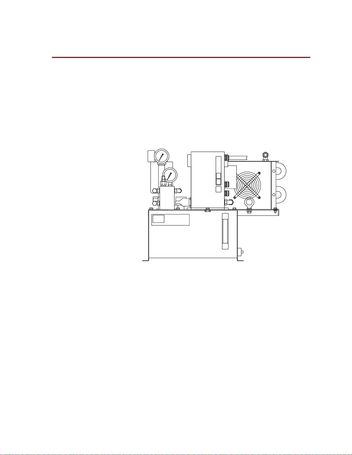
This manual documents the Model 512.01 Hydraulic Power Unit (HPU),
also called a hydraulic power supply, HPS, or pump. This compact
hydraulic power unit is designed for use with low force testing systems. It
includes an air cooled heat exchanger to maintain the operating
temperature range.
l
Model 512.01 Hydraulic Power Unit
What you need to
know
Model 512.01 Hydraulic Power Unit Introduction
MTS Systems Corporation assumes that you know how to use your
controller. See the appropriate manual for information about performing
any controller-related step in this manual’s procedures. You are expected
to know how to perform the following procedures:
• Using the controller hydraulic power unit controls in conjunction with
the control located on the HPU.
• Controlling hydraulic fluid flow to other hydraulic equipment.
5
Page 6

Functional Description
The hydraulic power unit (HPU) is the mechanical source of high-pressure
hydraulic fluid required to operate the hydraulic components of a test
system. See “Component Identification” on page 8 for more information
about the components described in this section.
Pump motor
Pressure
Filtering
Heat exchanger
A motor drives a hydraulic pump which draws hydraulic fluid from a
reservoir and pressurizes it to 6.9 MPa (1000 psi). The pressurized fluid is
made available to the hydraulic components in your test system.
The HPU pressure output is adjusted with a pressure reducing valve which
is factory set to 6.9 MPa (1000 psi). If the output pressure exceeds the
pressure setting, a pressure relief valve shunts the excessive pressure to the
hydraulic return line. The output pressure can be set to 6.9 MPa (1000 psi)
or less.
The filtration system protects against silting by cleaning the hydraulic fluid
to an ISO particle count of 14/10 or better. The filter change gage indicates
when the filter needs to be changed.
A suction strainer protects the pump from larger particles when the fluid is
pumped from the reservoir. It is located in the bottom of the hydraulic fluid
reservoir.
Hydraulic fluid temperature is maintained with a heat exchanger that cools
the fluid. The heat exchanger helps keep the temperature of the hydraulic
fluid between 43–52°C (109–126°F). The temperature of the fluid is
monitored by an overtemperature switch. If the fluid temperature exceeds
55ºC (130ºF), a switch opens and shuts down the HPU. The system cannot
be restarted until the fluid cools.
6
Electronics
Introduction
The air-cooled heat exchanger cools the hydraulic fluid as it passes
through a radiator. A fan blows air through the radiator to transfer heat
from the radiator to the air.
The HPU has basic controls to turn it on and off. The HPU includes a
connector to add a remote Emergency Stop switch. The HPU requires an
Emergency Stop switch or a jumper plug to be installed in order to run.
Model 512.01 Hydraulic Power Unit
Page 7
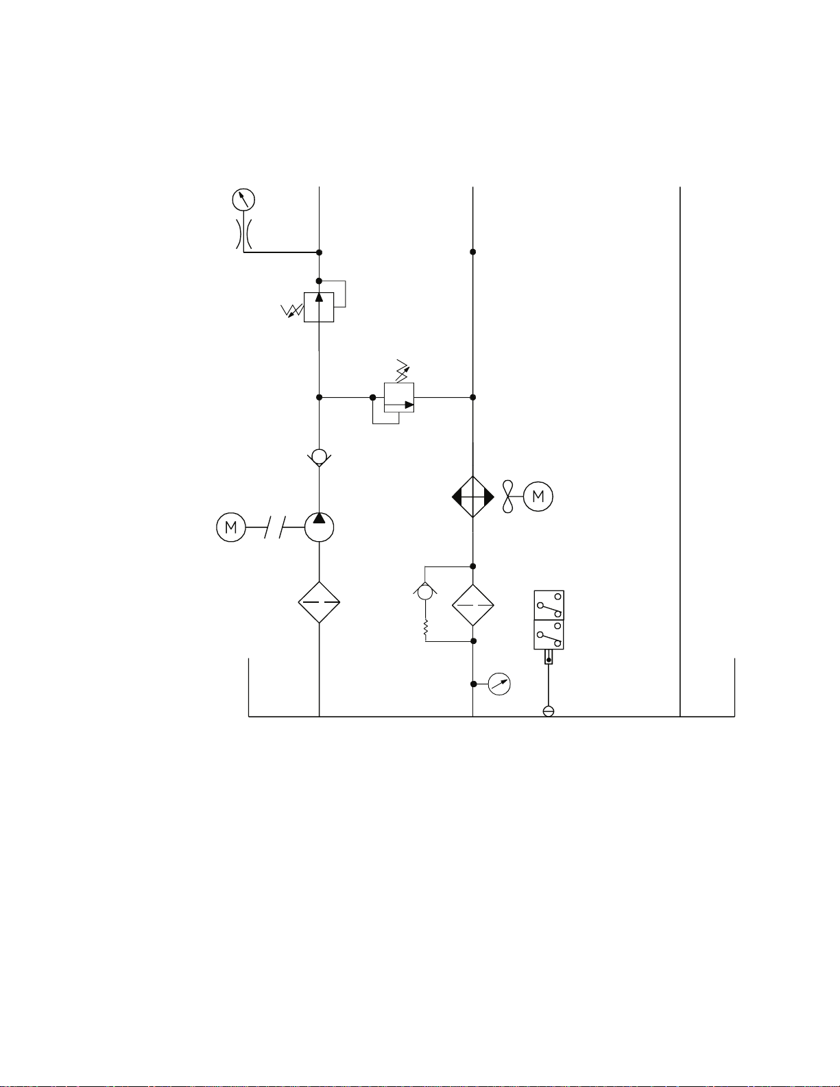
Hydraulic
schematic
Pressure
Gage
Pressure
Reducing
Valve
Motor
The hydraulic schematic shows how the hydraulic components are
connected in the Model 512.01 Hydraulic Power Unit.
Pressure -6
37° JIC Flare
Check
Valve
Set at 7 MPa
(1000 psi)
Set at 7.9 MPa
(1150 psi)
Pressure
Relief
Valve
Return -6
37° JIC Flare
Air-Cooled Heat
Exchanger
Drain -06
37° JIC Flare
1/2 NPT
Strainer
Pump
Filter
with
Bypass
Temperature Gage
Fan and Motor
Overtemperature
Switch
Set at 55°C (130°F)
Low Fluid
Switch
Model 512.01 Hydraulic Power Unit Introduction
7
Page 8

Component Identification
This table describes the components shown in the figure called
“Component Identification” on page 9.
Component Descriptions
OMPONENT
C
Filter
Low Fluid and
Overtemperature Sensor
Pump Motor
Jumper Plug
Control Box
Start Button
Stop Button
Reset Button
Heat Exchanger
Fluid Thermometer
D
ESCRIPTION
Provides 3–micron filtration to fluid returning to the reservoir (see
“Changing the Filter” on page 24).
Shuts the pump off if fluid becomes hotter than 55ºC (130ºF) or it detects
a low fluid level. See “Reducing the Fluid Temperature” on page 20 or
“Adding Hydraulic Fluid” on page 21 for more information.
Drives a fixed displacement gear pump.
Allows the HPU to run. Either the jumper plug or an external
Emergency Stop switch must be plugged into the control box before
the HPU can be started.
Houses the electronic controls for the pump, including the start button,
stop button, reset button, and the thermal overloads.
Turns the pump on. It produces an output of 6.9 MPa (1000 psi).
Turns the pump off.
Resets the thermal overloads of the HPU. See “Resetting the Thermal
Overloads” on page 22.
Cools the hydraulic fluid using an air cooled heat exchanger.
Displays the temperature of the hydraulic fluid.
Filter Change Gage
Pressure Gage
Reservoir
Sight Glass
Introduction
8
Shows when it is time to change the hydraulic filter. The gage is marked
with three zones: green, yellow, and blue.
Green—The filter is good to use.
Yellow—Change the filter soon.
Red—Do not run the HPU until you have replaced the hydraulic filter
element.
Shows the current output pressure from the HPU. The output pressure is
factory set to 6.9 MPa (1000 psi). See “Adjusting the Output Pressure” on
page 23 to change the output pressure.
Stores the hydraulic fluid. The reservoir has a 40 L (10 gal) capacity. It
includes a magnetic drain plug to help catch metal particles.
Let’s you see the hydraulic fluid. You can quickly check the hydraulic
fluid’s temperature, level, and condition (by its color).
Model 512.01 Hydraulic Power Unit
Page 9
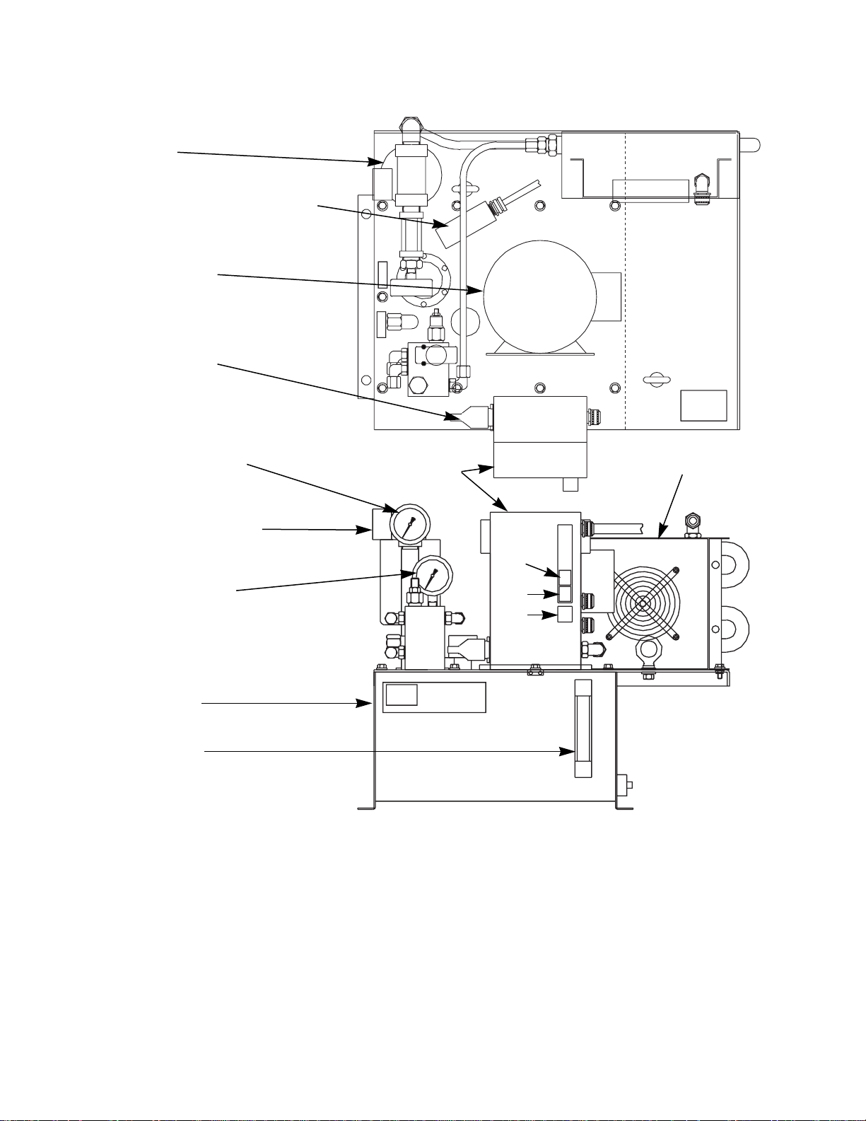
Filter
Low Fluid/Over Temp. Sensor
Pump Motor
Jumper Plug
Fluid Thermometer
Filter Change Gage
Pressure Gage
Reservoir
Sight Glass
Control Box
Start
Stop
Reset
l
Component Identification
Heat Exchanger
Model 512.01 Hydraulic Power Unit Introduction
9
Page 10

Specifications
Model 512.01 Specifications
ARAMETER
P
Environmental
Operating temperature
Heat load
Noise rating
Pump
Flow capacity
at 6.9 MPa (1000 psi)
Motor rating
Operating voltage
Starter type
Hydraulic Fluid
Nominal temperature
Filtration (microns)
Reservoir capacity
Heat exchanger
*
†
at 1 m
PECIFICATION
S
18–35°C (65–95°F)
480 kcal/hr (1900 BTU/hr)
70 db (A)
3.8 l/m (1.0 gpm) @ 60 Hz
0.56 kW (0.75 hp)
115 V (ac) @ 13.8 A, 1 phase
Line voltage
Mobil DTE 25
®
or Shell Tellus 46
46°C (115°F)
3 µ absolute
40 L (10 gal)
Air cooled
®
Hydraulic connections
Pressure
Return
Drain
Weight
*
Specification is for 60 Hz operation.
†
Free field value [75 db (A) ≈ heavy traffic at 17m]. Your readings
each requires a 37° JIC flare
-6
-6
-6
88.5 kg (195 lb)
may be up to 10 db (A) more.
10
Introduction
Model 512.01 Hydraulic Power Unit
Page 11

Dimensions
The following figure shows those dimensions which are useful when
installing the HPU.
563 mm
(22 in)
254 mm
(10 in)
480 mm
(19 in)
l
406 mm
(16 in)
584 mm
(23 in)
Model 512.01 Hydraulic Power Unit Introduction
11
Page 12

12
Introduction
Model 512.01 Hydraulic Power Unit
Page 13

Installation
This section describes how to install the Model 512.01 Hydraulic Power
Unit (HPU). The following figure show the components referenced in the
installation procedure.
Lift Ring
Dirty Filter Gage
Pump
Drain Line Connection
Breather
Thermometer
Output Pressure Gage
Return Line Connection
Pressure Line Connection
Heat Exchanger
Power Cord
Start
Stop
Reset
E-Stop Connector
Model 512.01 Hydraulic Power Unit Installation
l
Lift Ring
Sight Gage
Component Identification
13
Page 14

1. Position the hydraulic power unit.
You should determine where to put the hydraulic power unit (HPU).
Since it is connected to the other hydraulic equipment through
hydraulic lines, the HPU can be located remotely.
• Use the lifting rings (with a crane or fork lift) to move the HPU
unit into place.
• The HPU must be located where adequate air movement is
available. A clearance of 50 mm (2 ft) is required between the
heat exchanger and a wall.
• The base of the HPU has four holes to secure the unit in place.
2. Connect an external Emergency Stop switch.
An optional Emergency Stop switch can be connected to the 14 pin
CPC connector located on the control box.
A jumper plug is required if a remote Emergency Stop switch is not
installed. The HPU will not run without an Emergency Stop switch or
a jumper plug installed.
L1
L2
Green
1
1
3
8
9
Remote
Emergency
Stop Switch
CPC-14S
A Jumper Plug is required
if a Remote Emergency
Stop Switch Not
Connected
1 A
3
8
9
3. Connect the electrical service to the HPU.
NOTE You may want to have an electrician complete this step. Also, local
electrical codes supersede any information found here.
Plug the power cord into a 115 V (ac), 60 Hz, 1 phase outlet rated for
20 A. The electrical schematic is provided if you need to check any
wiring. This unit must be grounded.
M
OL
M
OL
OL
Varistor
Fan and Motor
Stop Switch
FU1
Start
Switch
SS1
M–1
TAS
Opens at
55° (130°)
M
Low Fluid
Switch
(opens at
70% full)
OL
14
Installation
Electrical Schematic
Model 512.01 Hydraulic Power Unit
Page 15

4. Test the HPU.
A. Remove the 1/2” NPT pipe plug and install the breather in the
reservoir cover.
B. Make sure all the pressure, return, and drain port caps are in
place.
C. Press the Start button (be sure the Stop button is released).
D. Check that the output pressure is less than 6.9 MPa (1000 psi).
E. Press the Stop button.
5. Connect the hydraulic lines.
See “Component Identification” on page 13 to determine the locations
of the hydraulic connections to the HPU. See the following table to
identify the size of each hydraulic connection.
Hydraulic Connectors
15
CONNECTOR SIZE
Pressure, 37º flare -6
Return, 37º flare -6
Drain, 37º flare -6
NOTE Some maintenance procedures require you to set the HPU for a no-
flow condition (where no fluid is flowing to other hydraulic
equipment). You may want to consider plumbing in a bypass circuit
in the system hydraulic lines.
Model 512.01 Hydraulic Power Unit Installation
Page 16

16
Installation
Model 512.01 Hydraulic Power Unit
Page 17

Operation
The following procedure is a guideline, and it assumes you are starting the
hydraulic power unit (HPU) after it has been turned off for some time (the
hydraulic fluid is considered cool). You may want to incorporate portions
of this procedure into your system startup sequence.
1. Check the fluid level in the sight gage. The hydraulic fluid should be
close to the top of the sight glass. If you need to add fluid, add 1 liter
(1 quart) at a time.
Normal Level
No Fluid Visible
Check the Fluid Level
2. At your test controller, make sure hydraulic pressure is turned off.
NOTE Some controllers can remotely control the HPU. The Model 512.01
Hydraulic Power Unit does not support this feature.
3. Turn the Start button turn the HPU on and wait for the motor to get
up to speed.
4. Check the output pressure for the correct output pressure. Pressure is
factory set for 6.9 MPa (1000 psi).
If the pressure is higher or you want to reduce the pressure setting,
see “Adjusting the Output Pressure” on page 23.
After the output pressure is achieved, turn on the hydraulic pressure at
the controller.
Model 512.01 Hydraulic Power Unit Operation
17
Page 18

5. Check to make sure the filter change gage’s needle stays in the green
zone.
NOTE Cold fluid may push it temporarily into the yellow or red zone.
If the needle stays in the yellow or red zone, turn the HPU off and
change its filter (see “Changing the Filter” on page 24).
CAUTION
Do not run the HPU if the filter gage is in the red region.
When the gage needle stays in the red zone, some hydraulic fluid is
bypassing the filter. This unfiltered fluid can wear or damage hydraulic
components.
Turn the HPU off when the filter gage reaches the red zone and change the
filter.
Yellow Zone
(warning to change)
Green Zone
(normal)
Red Zone
(do not operate)
Check the Filter Change Gage
6. Run the HPU for 1 hour to get the hydraulic fluid up to the operating
temperature of 43–52°C (109–126°F).
18
Operation
7. Once the hydraulic fluid is up to the operating temperature, you can
use the hydraulic system.
8. To turn the HPU off, press the STOP switch.
Model 512.01 Hydraulic Power Unit
Page 19

Maintenance
Contents Reducing the Fluid Temperature 20
Resetting the Thermal Overloads 22
Adjusting the Output Pressure 23
Changing the Filter 24
Changing the Hydraulic Fluid 25
Maintenance Intervals
WHAT TO DO WHEN TO DO IT
Recover from an abnormal shutdown as needed–when the HPU suddenly stops running
Lower the output pressure as required by your test needs
Lubricate the pump motor every six months
Change the filter when the filter gage needle stays in the yellow or red zone;
whenever you change hydraulic fluid
Change the fluid Verify the fluid condition by analysis or if the fluid’s condition
becomes poor
Abnormal
shutdowns
Any one of the following can cause your HPU to suddenly shut down. Y ou
will not be able to restart your HPU until you correct the condition.
PROBLEM SOLUTION
The hydraulic fluid exceeds
55ºC (130ºF).
The hydraulic fluid cannot be seen in
the sight glass (or it is at a low level).
A tripped thermal overload or blown
fuse in the control box removed
power from the unit.
See “Reducing the Fluid
Temperature” on page 20.
See “Adding Hydraulic Fluid” on
page 21.
See “Resetting the Thermal
Overloads” on page 22.
Model 512.01 Hydraulic Power Unit Maintenance
19
Page 20

Reducing the Fluid Temperature
The hydraulic power unit (HPU) will be shut down if the hydraulic fluid
reaches a temperature of 55°C (130° F).
1. Check the thermometer. The HPU shuts down when fluid gets hotter
than about 55ºC (130ºF).
2. Press the Start button. Hold it down to override the overtemperature
sensor.
• If overtemperature fluid caused the shutdown, the HPU will now
start to run.
• Keep holding the Start button until the HPU stays running when
you let go of this button. This could take several minutes.
If the HPU still does not run, something else caused the shutdown.
3. Once the HPU is running, put the HPU in a no-flow condition (where
no fluid is flowing to other hydraulic equipment).
4. Let the HPU run. Wait 15 minutes for its temperature to stabilize.
Check the fluid temperature.
If the temperature is between 43 and 52ºC (109 and 126ºF), stop.
20
Maintenance
Model 512.01 Hydraulic Power Unit
Page 21

Adding Hydraulic Fluid
1. The hydraulic power unit (HPU) will shut down when fluid drops
below the sight glass. Normally, it should be close to the top of the
sight glass.
No Fluid Visible
Normal Level
CAUTION
Check the Fluid Level
Do not mix different brands of hydraulic fluid.
Mixing different brands of hydraulic fluid can contaminate your system.
Call MTS if you are not sure what brand of hydraulic fluid your system uses.
2. Open the filler cap. If you add fluid, add it 1 liter (1 quart) at a time.
NOTE Be sure the fluid you add is prefiltered since it may not be clean.
3. Replace the cover cap.
4. Start the HPU.
Model 512.01 Hydraulic Power Unit Maintenance
21
Page 22

Resetting the Thermal Overloads
The thermal overloads of the hydraulic power unit (HPU) can be tripped
by the following conditions:
• Poor motor ventilation
• The output pressure is set too high
• A pump or motor is seizing
The thermal overloads are located in the control box.
WARNING
Do not open the control box unless the line voltage is turned off. When
power is present in the control box, high voltage and amperages are also
present.
You can be electrocuted if you touch the wrong component in the control
box.
Disconnect the HPU from power before opening the control box.
1. Press RESET on the control box cover.
• If it’s tripped, reset it and try restarting the HPU.
• If it trips again, turn the
HPU off before opening
Varistor
the control panel.
2. Disconnect the HPU from its
electrical power source.
Fuse
3. Unscrew the clamps holding
the control panel’s door shut.
4. Check for a blown fuse. A
defective varistor can also
Jumper
Plug
cause this fuse to blow. The
replacement fuse must have
the same rating as the blown
fuse.
22
Maintenance
5. Shut the control box door. Use
the clamps to hold it in place.
6. Reconnect the HPU to its electrical power source.
7. Restart the HPU. If the HPU will not restart or shuts down right away,
call MTS.
Model 512.01 Hydraulic Power Unit
Page 23

Adjusting the Output Pressure
The hydraulic power unit (HPU) comes with its output pressure set at
6.9 MPa (1000 psi) and a pressure relief setting of 7.9 MPa (1150 psi).
Special testing needs may require you to lower this pressure.
Pressure Relief Valve
Factory Set to
7.9 MPa (1150 psi)
Output Pressure
Adjustment Factory
Set to 6.9 MPa
(1000 psi)
CAUTION
Pressure A djustment Locations
Do not set the output pressure higher than 6.9 MPa (1000 psi).
Setting the output pressur e abo v e 6.9 MP a (1000 psi) can damage the pump
and its motor.
Set the output pressure no higher than 6.9 MPa (1000 psi).
1. Put the HPU into a no-flow condition (where no fluid is flowing to
other hydraulic equipment).
2. Press the Start button on the control box.
3. Wait for the fluid to reach the operating temperature of 43 and 52ºC
(109 and 126ºF).
4. Hold the setscrew in the
pressure reducing valve with a
5/32–inch hex key. Loosen the
locknut with a 9/16–inch
Pressure Gage
Setscrew
Locknut
wrench.
5. Turn the setscrew while
watching the gage until you get
the output pressure you want.
6. Hold the setscrew and tighten
down the locknut.
Model 512.01 Hydraulic Power Unit Maintenance
23
Page 24

Changing the Filter
Change the filter whenever the filter change gage’s needle stays in the
yellow or red zone with the hydraulic fluid at operating temperature.
Also, change the filter whenever you change the hydraulic fluid.
Special equipment needed–
• Oil filter wrench
• 3–micron oil filter (part number 119515-21)
1. Press STOP to turn the hydraulic power unit (HPU) off.
2. Use an oil filter wrench to loosen the old filter. Screw the filter
counterclockwise to remove it.
Change Filter
CCW
3. Wet the new filter’s gasket with clean hydraulic fluid.
4. Screw the filter clockwise to install it. Turn the new filter until its
gasket touches its sealing surface. Then hand tighten the filter 1/2
turn.
NOTE Tightening the filter with a wrench will not make it seal better, but it
will make it harder to remove the next time.
5. Press the Start button to turn the HPU on. Let the HPU run a few
minutes and check for leaks.
24
Maintenance
Model 512.01 Hydraulic Power Unit
Page 25

Changing the Hydraulic Fluid
As part of your regular HPU maintenance, change the hydraulic fluid every
2,500 hours of operation or if fluid analysis indicates the fluid should be
changed. However, you must change it immediately if any of the following
is true:
• The fluid becomes very dark and has a strong burnt sugar smell
(severe overheating).
• Particles appear in the sight glass (indicate a collapsed pickup
strainer).
• Fluid becomes milky (water in the fluid–a possible leaking heat
exchanger).
It is a good idea to keep a small jar of new hydraulic fluid for comparison
purposes.
Recommended
equipment
The following equipment (or its equivalent) is needed in the for this
procedure.
• A transfer pump with a 10–micron filter
• A 125 kg (250 lb) capacity hoist
• Synasol® or a similar cleaning solvent
• Lint-free cloths or manufactured rags
• A small drain that will fit underneath the drain plug
See “Component Locations” on page 26 to identify the components called
out in the following procedure.
1. Prepare the HPU.
A. Press STOP to turn off the HPU.
B. Remove electrical power to the HPU (via the circuit breaker at the
power source or by unplugging the HPU).
C. Remove the filler cap’s strainer assembly.
2. Remove the hydraulic fluid.
A. Remove the transfer pump’s filter (you do not need to filter the
dirty hydraulic fluid when removing it).
B. Use the transfer pump to remove the old hydraulic fluid out of the
reservoir.
C. Remove the drain plug to drain any remaining fluid.
Model 512.01 Hydraulic Power Unit Maintenance
25
Page 26

Filler Cap
Reservoir
Cover Screws
Pump Filter
Lift the cover with
these lift rings)
Suction Strainer
WARNING
l
Drain
Component Locations
Synasol is toxic and flammable.
Use the Synasol solvent in a ventalat ed ar ea and keep it away from an open
flame.
Follow the cautions and warnings on its container.
26
Maintenance
Model 512.01 Hydraulic Power Unit
Page 27

3. Clean the reservoir.
A. Unscrew the cover screws attaching the cover plate to the
reservoir.
B. Attach scraps to the cover plate’s two lifting eyes. Lift the cover
plate clear of the reservoir.
C. Clean the inside of the reservoir using clean cloths dampened
with Synasol. Clean the pump and bottom of the cover plate as
well.
D. Inspect the pump’s suction strainer. Replace this strainer if it is
plugged or damaged.
E. Lower the cover plate back down onto the reservoir.
F. Wipe off the magnetic drain plug and install it.
G. Tighten the four screws that attach the cover plate to the
reservoir.
CAUTION
Do not mix different brands of hydraulic fluid.
Mixing different brands of hydraulic fluid can contaminate your system.
Call MTS if you are not sure what brand of hydraulic fluid your system uses.
4. Add new hydraulic fluid to the reservoir.
A. Install the transfer pump’s 10–micron filter.
B. Pump clean hydraulic fluid into the reservoir. Stop when the fluid
level gets close to the top of the sight glass.
C. Install the filter cap’s strainer assembly.
D. Change the filter (see “Changing the Filter” on page 24).
5. Run the HPU.
Press the Start button. Run the HPU in a no-flow condition (where not
no fluid is flowing to other hydraulic equipment) for about one hour
to filter the new hydraulic fluid.
Model 512.01 Hydraulic Power Unit Maintenance
27
 Loading...