

Page 1

Hydraulic Power Unit
Product Information Manual
Model 506.82
Model 506.92
011-770-700 F
Page 2

Copyright information © 2000 MTS Systems Corporation. All rights rese rved.
Trademark information MTS is a registered trademark of MTS Systems Corporation.
DTE is a registered trademark of Mobil Corporation.
Tellus is a registered tradema r k of Shell Oil Corporation.
Contact information MTS Systems Corporation
14000 Technology Drive
Eden Prairie, Minnesota 55344-2290 USA
Toll Free Phone: 800-328-2255 (within the U.S. or Canada)
Phone: 952-937-4000 (outside the U.S. or Canada)
Fax: 952-937-4515
E-mail: info@mts.com
http://www.mts.com
Publication information
Manual Part Number Publication Date
011-770-700 F
June 1997
Page 3

Table of Contents
Section 1 Introduction
1.1 Functional Description............................................................................. 1-2
1.2 Specifications........................................................................................... 1-3
Section 2 Operation
2.1 Controls and Indicators............................................................................ 2-1
2.2 Operation Procedures .............................................................................. 2-3
2.3 Supercharge Pump Operation .................................................................. 2-5
Section 3 Service
3.1 Maintenance Procedures.......................................................................... 3-1
3.1.1 Filters ................................................................................................ 3-2
3.1.1.1 High-Pressure Filter Replacement ................................................ 3-3
3.1.1.2 Low-Pressure Filter Replacement ................................................. 3-4
3.1.2 Hydraulic Fluid................................................................................. 3-5
3.1.3 Accumulators .................................................................................... 3-7
3.1.3.1 Precharge Pressure-Checking Intervals......................................... 3-7
3.1.3.2 Precharging the Accumulators..................................................... 3-8
3.1.3.3 Changing the Accumulator Seals.................................................. 3-8
3.2 Service Adjustments................................................................................. 3-9
3.2.1 Adjusting the Output Pressure........................................................... 3-10
3.2.2 Dual-Temperature Switch Adjustments.............................................. 3-12
3.2.3 Low-Level Switch Adjustment........................................................... 3-13
3.2.4 Main Pump Low-Inlet Pressure Switch Adjustment ........................... 3-14
3.3 Starter Assembly..................................................................................... 3-15
3.3.1 Abnormal HPS Shutdown................................................................. 3-16
3.3.2 Fuse Replacement............................................................................. 3-16
3.3.3 PLC Service...................................................................................... 3-17
Section 4 Installation
4.1 Hydraulic Connections............................................................................ 4-2
4.2 Electrical Connections.............................................................................. 4-3
4.2.1 Transformer Wiring ........................................................................... 4-4
4.2.2 Input Power ...................................................................................... 4-5
4.3 Cooling Water Connections ..................................................................... 4-6
Table of Contents i
Page 4

Section 5 Theory of Operation
5.1 Hydraulic Operation................................................................................ 5-1
5.2 Electrical Operation ................................................................................. 5-3
5.2.1 Control.............................................................................................. 5-4
5.2.2 Interlocks .......................................................................................... 5-5
Index
List of Figures
Figure 2-1 Controls and Indicators ........................................................................... 2-1
Figure 3-1 Location of Maintenance Components (HPS Side View)........................... 3-1
Figure 3-2 Location of Accumulators........................................................................ 3-7
Figure 3-3 Location of Adjustment Components (HPS Side View) ............................. 3-9
Figure 3-4 Models 506.82/.92 Starter Assembly (Typical).......................................... 3-15
Figure 3-5 Fixed Controller with Remote Control Modules...................................... 3-16
Figure 4-1 Location of Remote Control Connector.................................................... 4-1
Figure 4-2 Hydraulic Connections............................................................................ 4-2
Figure 4-3 Models 506.82 and 506.92 Starter Assemblies ............................................ 4-3
Figure 4-4 Standard Transformer Wiring Configuration............................................. 4-4
Figure 4-5 Typical Multi-Tap Transformer Wiring Configuration............................... 4-4
Figure 5-1 Hydraulic Block Diagram........................................................................ 5-1
Figure 5-2 Typical Electrical Schematic..................................................................... 5-7
List of Tables
Table 1-1 Cooling Water Flow Requirements .......................................................... 1-3
Table 1-2 HPS Specifications ................................................................................... 1-3
Table 2-1 Controls and Indicators............................................................................ 2-2
Table 3-1 Maintenance Schedule ............................................................................. 3-2
Table 3-2 Starter Assembly Fuse Values.............................................................. ....3-16
Table 3-3 Fixed Controller Output Indicators.......................................................... 3-18
Table 3-4 Fixed Controller Input Indicators............................................................ 3-18
Table 3-5 Remote Control Module Output Indicators ............................................. 3-19
ii Table of Contents
Page 5
Section 1
Introduction
Definition
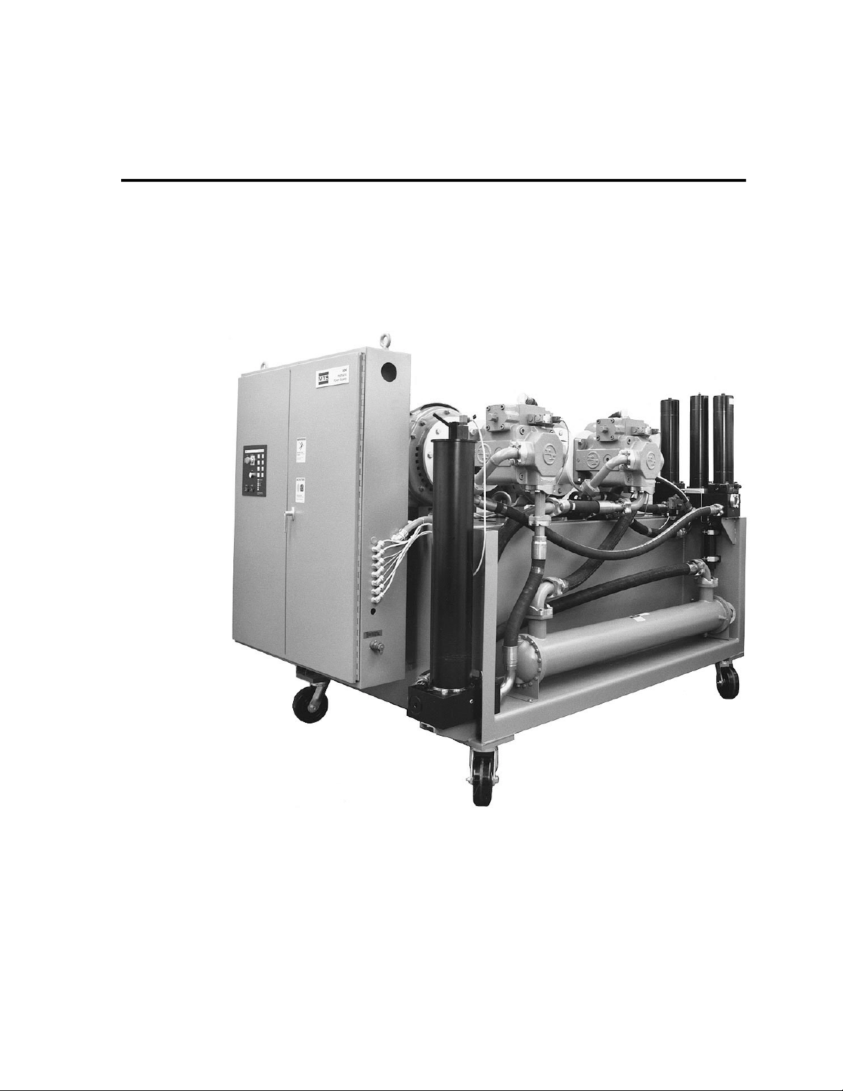
The Model 506.82/.92 Hydraulic Power Unit (HPU) uses two variablevolume (pressure compensated) main pumps, with a pressurized
(supercharged) hydraulic fluid inlet, to provide pressure to systems with
various flow requirements. The HPU is designed to be used with servocontrolled, electro-hydraulic systems.
Model 506.82/.92 Hydraulic Power Unit
Introduction 1-1
Page 6

1.1 Functional Description
Front panel controls
and indicators
Pressure output
Pressure
accumulation
Temperature
control
Fluid level indication
Front panel controls on the HPU include local operating controls and two
running time meters. Front panel indicators show power on, low oil
level, fluid over-temperature, motor overload and dirty filter conditions.
The output pressure is controlled by an adjustment on the main pumps
and is monitored by the output pressure gage. An adjustable back-up
relief valve limits output pressure by porting fluid back to the reservoir
when the output pressure rises above the relief valve setting.
High/low pressure operation is controlled by the high/low solenoid
valves. These valves control the main pressure control (pressure
compensator) vent ports and the backup relief valve vent port.
The pressure accumulator smoothes the HPU output pressure and
provides additional hydraulic flow for dynamic actuator demands. It is
precharged with dry nitrogen to a pressure proportional to HPU output
pressure. The slow turn-on accumulator slows the rate at which the
backup relief valve shifts from low to high pressure.
A temperature gage indicates hydraulic fluid temperature. An
oil-to-water heat exchanger controls the fluid temperature. When the
temperature exceeds a preset limit, a temperature sensitive switch turns off
the HPU and lights the front panel Over-Temperature indicator.
A transparent gage indicates the level of hydraulic fluid in the HPU
reservoir. A low-level switch automatically turns off the HPU and lights
the front panel Low Oil Level indicator if hydraulic fluid drops below a
preset level.
Programmable logic
controller
The PLC (programmable logic controller) located in the starter assembly
performs logic functions. The I/O (input/output) section of the PLC
provides an interface for various signals received from or sent to external
devices.
An optional module can be added to the PLC if remote control of the
HPU is required. This module provides the additional output indicators
needed for the remote control option.
Introduction 1-2
Page 7

1 .2 Specifications
Cooling water
specifications
General HPU
specifications
The required water pressure between the input and the output of the heat
exchanger is 30 to 45 psi (0.2 to 0.3 MPa). The maximum allowable
pressure is 120 psig (0.8 psid). The flow rate (±20%) at a given temperature
is shown in the table below.
Table 1-1. Cooling Water Requirements
Cooling Water Inlet Required Water Flow
Temperature 506.82B 506.92B
60°F (15.5°C) 30 gpm (114 l/min) 35 gpm (132 l/min)
65°F (18.5°C) 35 gpm (132 l/min) 42 gpm (159 l/min)
70°F (21.0°C) 40 gpm (151 l/min) 51 gpm (193 l/min)
75°F (24.0°C) 46 gpm (174 l/min) 67 gpm (254 l/min)
80°F (26.5°C) 54 gpm (204 l/min) 90 gpm (341 l/min)
85°F (29.5°C) 70 gpm (269 l/min) 120 gpm (454 l/min)
90°F (32.0°C) 90 gpm (346 l/min) 160 gpm (606 l/min)
Table 1-2 lists the specifications for the Model 506.82/.92 Hydraulic Power
Unit.
Table 1-2. HPU Specifications
Parameter Model 506.82B Model 506.92B
Maximum continuous pressure 3000 psi (20.7 MPa) 3000 psi (20.7 MPa)
Maximum flow capacity (60 Hz) 150 gpm (568 l/min) 200 gpm (757 l/min)
Maximum flow capacity (50 Hz) 150 gpm (568 l/min) 185 gpm (710 l/min)
Noise rating at 3 ft. (0.9 m) 90 dBa 90 dBa
Reservoir capacity:
Maximum full to top plate (no air) 571 gal ( 2161l) 571 gal ( 2161l)
Nominal running level, 28 in. (711 mm) above tank
bottom
Low-pressure filtration, absolute/nominal 3.0/0.45 microns 3.0/0.45 microns
High-pressure filtration 10 microns 10 microns
Fluid hose connections:
Pressure (SAE 4 bolt) -24 (1), -32 (1) -24 (1), -32 (1)
Return (SAE 4 bolt) -24 (1), -32 (1) -24 (1), -32 (1)
Drain (37° flare) -16 (1), -12 (1),
Main pump motor power rating (2 each) 150 hp (112 kW) 200 hp (150 kW)
*
463 gal (1753 l) 463 gal (1753 l)
-16 (1), -12 (1),
-8 (2)
-8 (2)
Introduction 1-3
Page 8

Table 1-2. HPU Specifications (Continued)
Parameter Model 506.82B Model 506.92B
Supercharge pump motor power rating 25 hp (19 kW) 40 hp (30 kW)
3-phase current 460V/60 Hz:
†
Inrush 575 A 775 A
Continuous 395 A 535 A
Starter type Wye-delta Wye-delta
24 V external hydraulic control amps (with optional
6.8 A 6.8 A
remote control)
Maximum cooling water heat load:
BTU per hour 760,000 1,020,000
Kilocalories per hour 192,000 257,600
Atmospheric heat load (BTU per hour) 56,900 87,800
Atmospheric heat load (Kilocalories per hour) 14,400 22,200
Water inlet/outlet size 1.5 in. (38 mm) NPT 2 in. (51 mm) NPT
Maximum ambient operating temperature 104°F (40°C) 104°F (40°C)
Minimum ambient operating temperature 40°F (4.4°C) 40°F (4.4°C)
Height with casters 78 in. (1981 mm) 78 in. (1981 mm)
Length 111 in. (2819 mm) 111 in. (2819 mm)
Width 68 in. (1727 mm) 68 in. (1727 mm)
Weight with oil 12,500 lb (5669 kg) 12,500 lb (5669 kg)
* The number of connections are shown in parentheses.
†
Currents listed are typical theoretical values based on data outlined in the NEPA-70 (national
electrical code). Supply conductors and disconnect switch sizing must be done using the
customer’s local and state codes.
Specifications subject to change without notice. Contact MTS for verification of any critical specifications.
Introduction 1-4
Page 9
2.1 Controls and Indicators
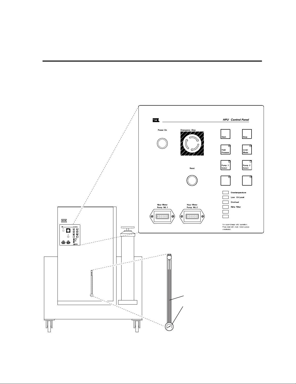
Figure 2-1 and Table 2-1 identify and describe HPU controls and indicators.
Section 2
Operation
Fluid Level Gage
Temperature Gage
(These gages are located on the
HPS rear panel)
Figure 2-1. Controls and Indicators
VW-G041C
Operation 2-1
Page 10

Table 2-1. Controls and Indicators
Control/Indicator Description
Power On indicator* The Power On indicator lights to indicate that electrical power is
applied to the HPU.
Emergency Stop switch This switch operates in both local and remote control and is
used during emergency situations only. When pressed, it
immediately shuts down the HPU (the supercharge pump may
continue to run briefly to supply the main pumps until they
fully stop).
Local Mode switch If the Local Mode switch is activated, you can operate the HPU
with the front panel controls. If it is not activated, use a remote
control device to operate the HPU. Activation lights an LED in
the upper right corner of the switch.
Start switch Pressing Start sequences supercharge and main motors on, then
applies low pressure when in local control.
High Pressure Pressing High Pressure applies high pressure in local control.
Start must be pressed before applying high pressure. Activation
lights an LED in the upper right corner of the switch. The LED
also lights if high pressure is requested remotely.
Stop switch When Stop is pressed (in either local or remote mode), the HPU
first ramps to low pressure and then goes to zero pressure. The
supercharge pump continues to run for approximately 15
seconds.
Reset switch This switch resets the interlock circuit if the condition causing
the interlock has been corrected.
Low Oil Level indicator When this indicator lights, the hydraulic fluid level has dropped
below a preset value.
Fluid level gage This gage indicates the level of hydraulic fluid in the reservoir.
Over-Temperature
indicator
Temperature gage This gage indicates the temperature of the hydraulic fluid in the
Dirty Filter indicator When this indicator lights, the low-pressure filter needs
Pump 1 Select Pressing this switch selects Pump 1 for operation. Activation
Pump 2 Select Pressing this switch selects Pump 2 for operation. Activation
Hour Meter
Pump No. 1
Hour Meter
Pump No. 2
When this indicator lights, hydraulic fluid temperature has
exceeded a preset value.
HPU reservoir.
replacement. See Subsection 3.1.1.
lights an LED in the upper right corner of the switch.
lights an LED in the upper right corner of the switch.
This front panel meter indicates the total operating hours of
pump 1.
This front panel meter indicates the total operating hours of
pump 2.
Operation 2-2
Page 11

2.2 Operation Procedures
WARNING
!
This section provides the local and remote operating procedures for the
506.82/.92 Hydraulic Power Unit.
Do not start the HPU if the servovalve command is not equal to feedback
(that is, zero balanced).
Failure to do this can result in sudden actuator movement which may
cause injury to persons and/or damage to equipment.
Ensure that the system is at zero balance before starting the HPU.
Before you begin
Local operation
Before you begin operation complete the following steps:
1. Make sure that the external hydraulic system is ready for operation.
2. Press the Pump 1 Select or Pump 2 Select switch to select main pump
operation.
NOTE
To operate the HPU in local control mode complete the following steps:
1. Press the Local Mode switch to run the HPU in local control.
Activating this switch lights an LED in its upper right corner.
2. Apply electrical power to the HPU (the Power On indicator will
light).
3. Press Reset (must be pressed whenever electrical power to the HPS
has been interrupted).
The Dirty Filter indicator may light during a cold-start. It
should turn off when the HPU reaches its normal
operating temperature. If the indicator fails to turn off,
correct the condition (Subsection 3.1.1.2) and press Reset.
4. Press the Start switch to apply low pressure to the system.
5. Check the HPU and external hydraulic system for leaks and unusual
sounds.
6. Press the High Pressure to apply high pressure to the system.
7. Press Stop on the HPU front panel to stop the HPU and remove
output pressure.
Operation 2-3
Page 12
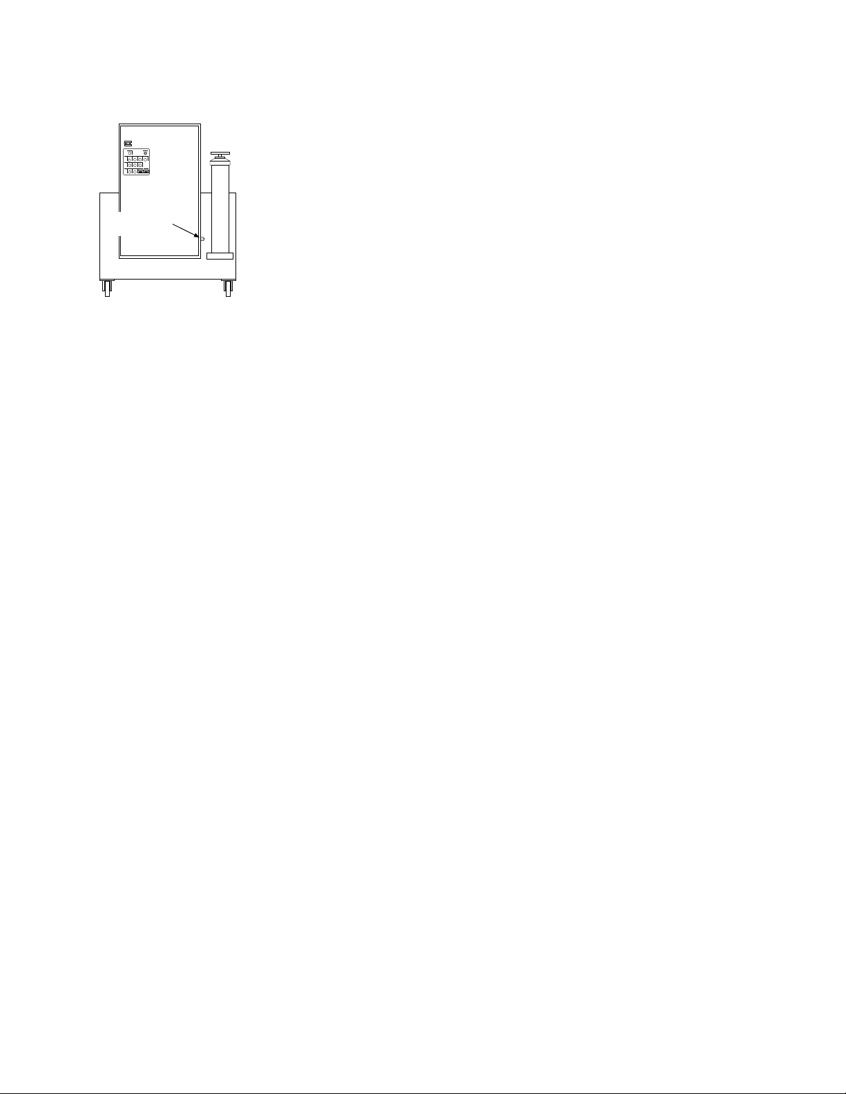
Remote Operation
1. Turn the Source Remote/Local switch to Remote. Make sure that
the remote control cable is connected to the cable connector (the
figure on the left shows the location of this connector) and to the
remote control device.
2. Apply electrical power.
remote control
connector
has been interrupted).
4. Use the remote control device to start the HPU at low pressure.
5. Check for leaks and unusual sounds.
3. Press Reset (must be pressed whenever electrical power to the HPS
VW-G045A
6. Select high pressure at the remote control device.
7. Use the Off switch on the remote control device to stop the HPU
and remove output pressure.
2.3 Supercharge Pump Operation
When to use the
supercharge pump
Cooling procedure
When the temperature of the hydraulic fluid in the HPU reservoir exceeds
140˚F (60˚C), the fluid over-temperature switch automatically shuts down
the HPU. The HPU main pumps cannot be restarted in local or remote
until the hydraulic fluid cools.
The following procedure uses the supercharge pump to hasten the cooling
of the hydraulic fluid:
1. Ensure the water supply to the heat exchanger is turned on.
2. Press the Start switch without pump motor 1 or 2 selected. The
supercharge pump operates independently of the main pumps and
circulates hydraulic fluid through the heat exchanger to cool the
fluid.
Operation 2-4
3. When the temperature gage reads approximately 130˚F (54˚C), press
the Stop switch to turn off the supercharge pump.
4. To restart the HPU, first press the Reset control on the local or remote
control panel to clear the hydraulic interlock circuit, and then start
the HPU in low pressure.
Page 13
Section 3
Service
Introduction
This section contains service information for the Model 506.82/.92
Hydraulic Power Unit (HPU). It provides:
• maintenance procedures
• service adjustments
• electrical information
3.1 Maintenance Procedures
Maintenance
overview
The following sections provide the routine maintenance procedures for
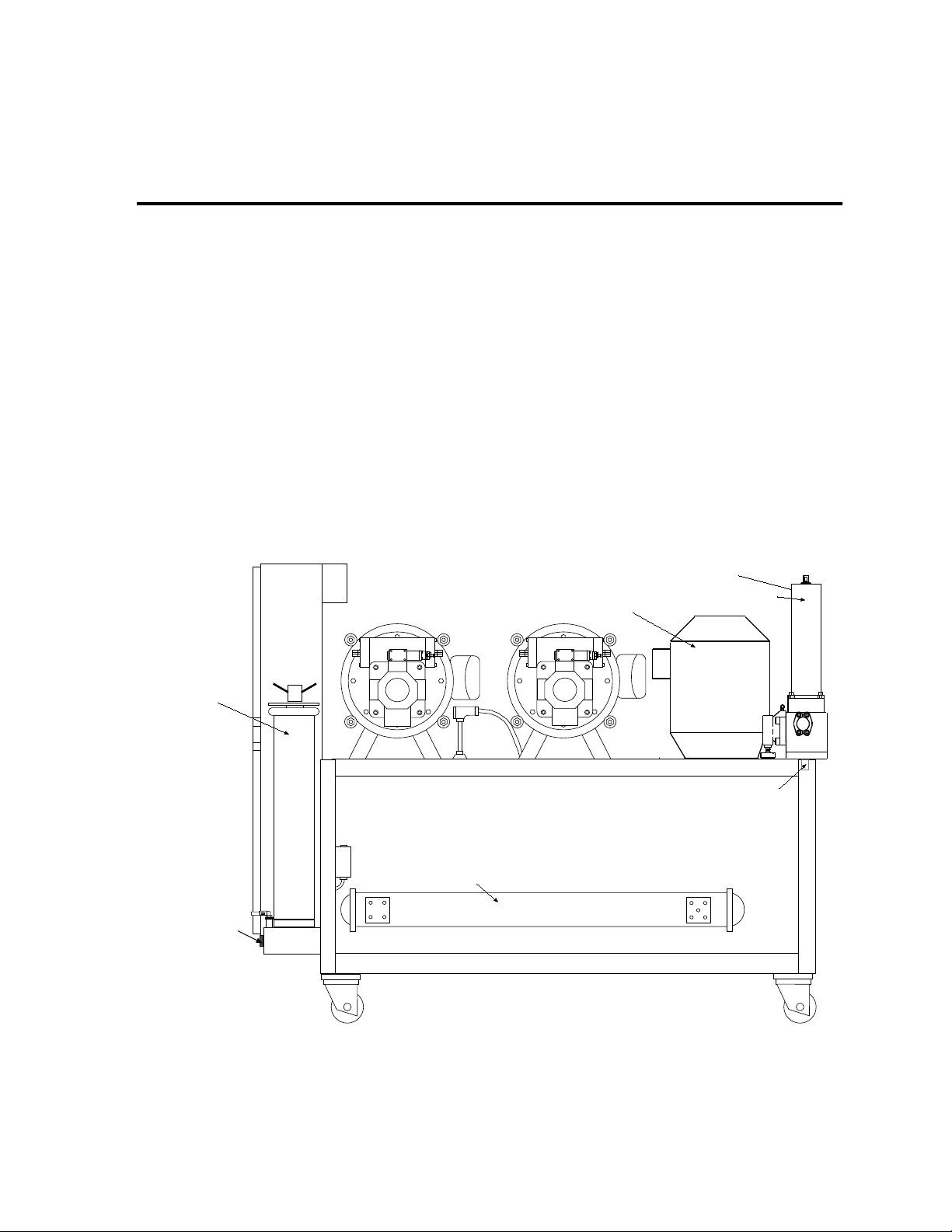
the HPU. Figure 3-1 shows the location of the components accessed for
the maintenance procedures. Table 3-1 lists the maintenance schedule.
low pressure filter
supercharge pump/motor
high pressure filters
pressure accumulator
filter drain
manifold drain
heat exchanger
VW-G043E
Figure 3-1. Location of Maintenance Components (HPU Side View)
Service 3-1
Page 14

Table 3-1. Maintenance Schedule
WARNING
!
Procedure Interval Subsection
Check output pressure on gage
*
daily
Replace high-pressure filter whenever the indicator points to
change
Replace low-pressure filter whenever Dirty Filter indicator lights 3.1.1
Check hydraulic fluid level on gage daily 3.1.2
Check hydraulic fluid in reservoir 150 operating hours 3.1.2
Analyze hydraulic fluid 500 operating hours 3.1.2
Check accumulator precharge at established interval 3.1.3
Check hydraulic hoses monthly
*
See Subsection 3.2.1 to adjust the output pressure.
3.1.1 Filters
Fluid filtration is provided by two 10-micron high-pressure filters (one for
each pump), and one 3-micron low-pressure filter. See Figure 3-1 for the
location of the filters and their drains.
3.1.1
3-2 Service
High-pressure release occurs if the system is pressurized.
High-pressure release may cause personal injury or damage equipment.
Ensure that the output pressure gage reads zero before replacing the
filters.
Page 15
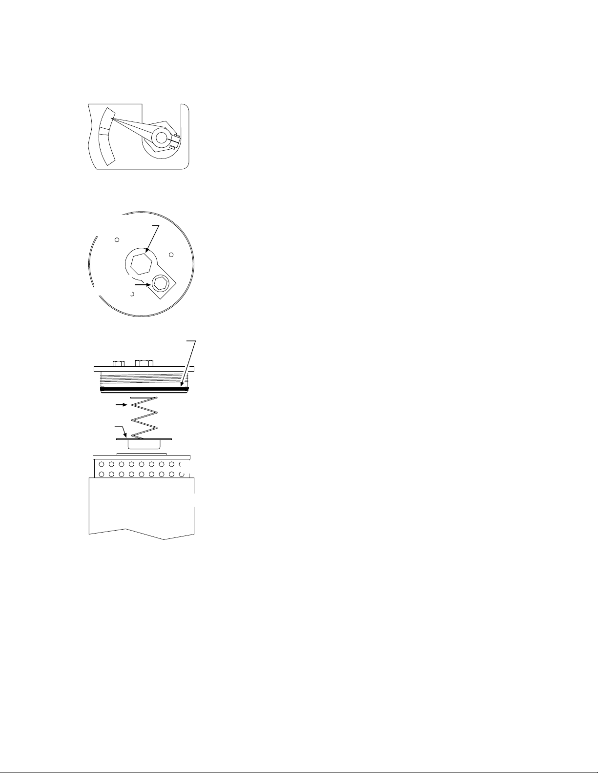
3.1.1.1 High-Pressure Filter Replacement
6
End Cap – Top View
r
g
O-ring and backup ring
CHANGE
OK
DIRT ALARM
unscrew to
remove endcap
unscrew to
bleed
Replace the high-pressure filter elements whenever the DIRT ALARM
indicator mounted on the base of each high-pressure filter housing
points to CHANGE (red or yellow zone) or whenever the hydraulic
fluid is replaced.
VW-GO4
1. Press Stop on the HPU. The output pressure gage must read zero.
2. Loosen the air-bleed screw on top of the filter housing endcap.
With a container under the manifold drain port (Figure 3-1), open
the port to drain the fluid for both filters (the pressure accumulator
also drains).
When the fluid is drained, close the drain port and tighten the airbleed screw. Discard the fluid according to company policy.
VW-GO47
3. Unscrew and remove the endcap. Remove the compression spring
plate on top of the filter elements and remove the filter elements.
4. Remove and save the grommet between the two filter elements.
Discard the filter elements.
spring
spring
plate
After you have
finished
filte
filter housin
VW-GO48
5. Inspect the O-ring and back-up washer in the end-cap. If
replacement is not required, clean and lubricate them with clean
hydraulic fluid.
6. Inspect the filter housing for any remaining contamination.
7. Insert two clean filter elements (MTS part number 100533-05), with
the grommet between the two elements, into the filter housing.
8. Inspect the compression spring plate and replace the end-cap.
Taking care not to damage the O-ring and the back-up washer,
tighten the end-cap.
Operate the HPU in low pressure for 5 minutes to remove air from the
filter housing. Check for leaks while doing this.
Service 3-3
Page 16

3.1.1.2 Low-Pressure Filter Replacement
g
The low-pressure filter element requires replacement whenever hydraulic
fluid in the HPU reservoir is replaced, or the Filter Dirty indicator on the
HPU front control panel lights.
See Figure 3-1 for the location of the filter. Refer to the figure on the
left to locate the components accessed for the following procedure.
1
bleed screw
with O-ring
O-ring
O-ring (supplied with
filter)
After you have
finished
filter
filter housin
VW-GO49
1. Press Stop on the HPU. The output pressure gage must read zero.
2. Disconnect the cable from the filter manifold.
3. Remove one of the two bleed screws at the top of the filter cover.
4. Place a container under the filter drain and drain the fluid. Dispose
of the fluid according to company policy.
5. Replace and tighten the bleed screw and drain plug.
6. Hand turn the handle counterclockwise until it screws off. Remove
the cover.
7. Remove and discard the filter element. Inspect the filter housing for
any remaining contamination.
8. Insert a new filter element (MTS part number 114028-17).
9. Hand tighten the cover. Reconnect the cable.
Purge the filter housing of air and allow it to fill with fluid as follows:
1. Open the bleed screw 1-1/2 turns.
2. Press the Reset control to reset the Filter Dirty indicator.
3-4 Service
3. Jog the supercharge pump motor by pushing the Start button with
neither main pump selected, then immediately pushing the Stop
button. Continue this procedure until hydraulic fluid appears at the
loosened bleed screw.
4. Close and tighten the bleed screw.
Page 17

3.1.2 Hydraulic Fluid
Regular maintenance of hydraulic fluid maximizes the service life of the
system and its components.
Daily fluid checks
Monthly fluid
checks
Check the fluid-level in the transparent gage. A low level can indicate a
leak. A high level can indicate water contamination from the heat
exchanger. If the fluid appears to have changed significantly, obtain a
sample from the HPU reservoir and check it for the following qualities:
• Considerable darkness, burnt odor, or an opaque quality of the fluid
indicates chemical breakdown. It may also indicate that the fluid
temperature was too high. Replace the fluid.
• During operation, a milky appearance indicates water is present in
the fluid. If the system is not in operation, water separates from the
hydraulic fluid and settles at the bottom of the reservoir. If water
contamination is present, correct the source of the water leakage and
replace the hydraulic fluid.
Perform these checks monthly or every 150 operating hours (whichever
comes first).
• Keep records of the maximum reservoir temperature. High operating
temperatures can cause the fluid to break down.
• Check for contamination and fluid breakdown. Take a fluid sample
and test the pH level using a pH kit (available from chemical stores).
Also, check the sample for color and odor.
• Take a fluid sample and let it stand overnight. Sediment at the bottom
of the fluid indicates collapsed, ruptured or clogged filters.
Yearly (every 500
operating hours)
fluid checks
Obtain a sample of the fluid and have it analyzed. The fluid tests should
include chemical analysis, particle count, and viscosity checks. Record the
results and replace the fluid if necessary.
Service 3-5
Page 18

Replacing hydraulic
CAUTION
!
fluid
Perform this procedure to replace the hydraulic fluid. You will need a
Model 590.01 Fluid Transfer Pump or a pump which provides at least
10-micron filtration.
HPS – Rear View
drain
VW-G042D
1. Turn off electrical power to the HPU. Remove the reservoir filler
cap assembly.
2. Drain the hydraulic fluid into a container, while hot, through the
drain valve. Close the valve.
Then drain the oil from the entire system (such as from the hoses
and accumulators).
Dispose of the fluid according to company policy.
3. Remove the top plate from the reservoir.
4. Wipe the inside of the reservoir with a clean lint-free cloth. Apply
MOBILSOL A—a solvent for cleaning and flushing hydraulic
systems—to a clean lint-free cloth and again wipe the reservoir.
Immediately wipe away the solvent with a dry cloth.
5. Replace the high-pressure filter element. See Subsection 3.1.1.1.
6. Replace the low-pressure filter element. See Subsection 3.1.1.2.
To avoid damage to the hydraulic system, follow these precautions:
Do not mix different brands of hydraulic fluid.
This can create contaminants. Ensure that the replacement hydraulic fluid
is the same brand and type as the fluid which was removed. Generally, an
MTS Hydraulic Power Unit contains Mobil DTE 25 hydraulic fluid.
Consult MTS before you use alternate fluids.
Use a transfer pump that provides 10-micron or better filtration.
Most commercial hydraulic fluids exceed the maximum amount of
contamination allowable in MTS hydraulic systems.
7. Use the transfer pump to fill the reservoir with fresh hydraulic fluid.
8. To flush out the pipe line, connect a hose from the pressure line to
the return line of the last station, and operate the HPU at low
pressure for 2 - 4 hours.
9. Replace the high-pressure filter if necessary (Subsection 3.1.1.1).
3-6 Service
Page 19

3.1.3 Accumulators
For more
information about
accumulators
See the Series 111 Accumulator product manual (MTS part number 115533XX). For other accumulators, refer to the vendor literature or the
Procedure for Checking Piston and Bladder Type Accumulator Precharge
and Precharging (MTS part number 408266-XX).
pressure accumulator
pressure gage
filter drain
slow turn-on
accumulator
Figure 3-2. Location of Accumulators
3.1.3.1 Precharge Pressure-Checking Intervals
Pressure
Accumulator
Precharge pressure of the pressure accumulator (Figure 3-2) must be
checked at regular intervals. To establish an interval time, follow this
procedure:
1. Initially, check the precharge pressure after 2 weeks or 100 operating
hours.
2. If the pressure changes more than 200 psi, check the precharge
pressure every week or 50 operating hours.
If the pressure changes less than 200 psi, check the precharge
pressure every four weeks or 200 operating hours.
back-up relief valve
Service 3-7
Page 20

Slow Turn-on
Accumulator
3.1.3.2 Precharging the Accumulators
3.1.3.3 Changing the Accumulator Seals
Precharge pressure of the slow turn-on accumulator (Figure 3-2) must be
checked at regular intervals. To establish an interval time, follow this
procedure:
1. Initially, check the precharge pressure after 2 weeks or 100 operating
hours.
2. If there is a pressure-level change of more than 50%, check the
precharge pressure every week or 50 operating hours.
If there is a pressure-level change of less than 50%, check the
precharge pressure every four weeks or 200 operating hours.
If the pressure accumulator has a pressure-level change of ±200 psi
between checks, recharge it. If the slow turn-on accumulator has a
pressure-level change of ±50% between checks, recharge it.
The pressure and slow turn-on accumulators are typically precharged to
1000 psi (7 MPa) and 800 psi (5.5 MPa), respectively. These are the
recommended levels for an HPU output pressure of 3000 psi (21 MPa).
When you have established a regular interval for checking the precharge
pressure, note the amount of pressure loss that occurs each time the
precharge pressure is checked. If an increase in pressure loss occurs
during the period between checks, the seals may require replacement.
3-8 Service
Page 21

3.2 Service Adjustments
pressure control - pump no. 1
e
t
Service overview
Figure 3-3 shows the location of the service components accessed for the
following procedures.
• output pressure adjustment
• dual-temperature switch adjustments
• low-level switch adjustment
• main pump low-inlet pressure switch adjustment
pressure control - pump no. 2
back-up relief valve
low-level switch
dual-temperatur
switch adjustmen
low-inlet presssure switch
Figure 3-3. Location of Adjustment Components (HPU Side View)
VW-G043G
Service 3-9
Page 22

b
3.2.1 Output Pressure Adjustment
Refer to Figure 3-2 for the location of the components indicated in the
following procedure.
1. Turn off the HPU.
2. Make sure that the output pressure gage reads zero (Figure 3-2 shows
the location of the pressure gage).
3. Remove the plastic cap on both pump pressure controls. Loosen the
locknuts and turn both pressure controls fully counterclockwise.
4. Loosen the locknut on the back-up relief valve and turn the
adjustment knob fully counterclockwise.
locknut
adjustment kno
VW-G050
5. Press Pump 1 Select on the HPU Control Panel.
6. Press Start to run the HPU at low pressure, then press High Pressure.
7. Observe the pressure gage and alternately turn the back-up relief
valve adjustment and the pressure control on pump 1 clockwise
(Adjustment increments should be approximately 500 psi (3.45 MPa)
apart as indicated on the pressure gage.).
Stop adjusting at approximately 500 psi (3.45 MPa) above the desired
output pressure (typically 3000 psi/21 MPa).
8. Tighten the locknut on the back-up relief valve.
9. Turn the pressure control on pump 1 counterclockwise until the
desired output pressure is reached.
10. Turn off the HPU.
3-10 Service
Page 23

11. Press Pump 2 Select on the HPU Control Panel.
12. Press Start to run the HPU at low pressure, then press High Pressure.
13. Turn the pressure control on pump 2 clockwise until output pressure
on the pressure gage reads approximately 100 psi (0.5 MPa) lower
than the pressure control 1 setting.
After you have
finished
NOTE
Replace the plastic caps removed in step 3.
Whenever the output pressure is changed, the accumulator precharge
must also be checked (see Subsection 3.1.3).
A differential pressure between the pressure setting of
pump 1 and pump 2 prevents crosstalk between the two
hydraulic circuits
Service 3-11
Page 24

3.2.2 Dual-Temperature Switch Adjustments
WARNING
!
Definition
temperature gage
The dual-temperature switch has two adjustment screws behind its front
protective cover. The Over Temperature adjustment turns off the HPU if
hydraulic fluid reaches a temperature of 140˚F (60˚C).
The Water Solenoid Control adjustment allows water flow to the heat
exchanger when an oil temperature of 105°F (40°C) is exceeded. The water
solenoid control is only used if the optional water solenoid valve is
required.
Do not touch the dual temperature switch’s electrical leads.
They carry 120 Vac. Touching them could give you a serious or even fatal
shock.
Perform this procedure wearing insulated gloves and using an insulated
screwdriver.
HPS – Rear View
Dual Temperature Switch – cover removed
adjustment screws
Before you begin
Over-temperature
adjustment
DO NOT TOUCH!
(read the Warning)
VW-G042E
Turn off the HPU. Loosen the screws on each side of the switch assembly,
and pull the front protective cover off. The adjustment screws are labeled.
1. Turn the over-temperature adjustment screw (figure above) several
turns clockwise to raise the temperature limit.
2. Turn off the water supply to disable the heat exchanger.
3. Turn on the HPU and apply high pressure (see Subsection 2.2).
4. When hydraulic fluid temperature reaches 140˚F (60˚C), as
indicated on the temperature gage, turn the adjusting screw
counterclockwise until the HPU turns off.
5. Turn on the cooling water supply.
3-12 Service
Page 25

Water control
adjustment
1. Start this procedure when the temperature gage shows that the
hydraulic fluid is below 90°F (32°C).
2. Start the HPU.
3. Make sure the square shaft on top of the water regulating valve is
turned fully counterclockwise to shut off water flow.
4. Monitor the temperature gage as the hydraulic fluid heats up.
5. When the fluid temperature reaches approximately 120°F (49°C),
turn the adjustment screw clockwise until water starts to flow.
Then turn this screw counterclockwise until water flow stops.
6. If the fluid temperature does not reach 125°F (52°C) turn the screw
a half-turn counterclockwise and note the effect after 15 minutes. If
the temperature exceeds 125°F (52°C), turn the screw clockwise.
7. After adjustments are completed, turn the square shaft on top of the
water regulating valve fully clockwise for full cooling water flow.
3.2.3 Low-Level Switch Adjustment
The low fluid-level switch turns off the HPU if there is an appreciable
loss of hydraulic fluid. The factory-adjustment coincides with the
bottom of the fluid level gage and does not normally require
readjustment. Perform the following steps if readjustment is necessary.
locknut
top of
reservoir
1. With the HPU turned off, fill the reservoir to the correct fluid level.
2. Turn on the HPU and apply high pressure.
3. See the figure on the left. Loosen the hand locknut on the stem of
VW-G051
the switch, and slowly raise the switch until the Low Fluid Level
indicator lights.
4. Lower the switch about 1.5 in. (38 mm).
5. Tighten the locknut.
6. Reset any applicable interlock circuits.
Service 3-13
Page 26

3.2.4 Main Pump Low-Inlet Pressure Switch Adjustment
2
The main pump low-inlet-pressure switch shown in the figure below
monitors the pressure level supplied by the supercharge pump at the input
to the main pumps. The switch protects the main pumps by turning off the
HPU if the supercharge pump pressure drops below the minimum level
required by the main pumps.
Pressure Switch –
Cover Off
adjustment knob
When to adjust the
switch
How to adjust the
switch
VW-G05
The switch is set at the factory to activate at 30 psi (0.21 MPa). This switch
may be adjusted with or without the HPU running.
Figure 3-3 shows the location of the switch on the HPU. Check the
position of the pressure setting indicator on the switch (see the figure
above and left). It should be set at 30 psi (0.21 MPa). If it is not, follow the
procedure below to adjust the switch.
Turn the adjustment knob located on top of the switch either clockwise to
increase the pressure setting or counterclockwise to decrease the pressure
setting to 30 psi (0.21 MPa).
3-14 Service
Page 27

3.3 Starter Assembly
WARNING
!
Control Relays
Transformer
s
The starter assembly is located behind the starter box door. Figure 3-4
shows the location of the starter assembly components.
High voltage is present in the starter assembly. Do not open the starter
box door when power is applied to the HPU.
Touching components with high voltage can cause death.
Remove electrical power at the power disconnect switch before you open
the front starter box door.
PLC
Fuse
Motor Relays
Figure 3-4 Models 506.82/.92 Starter Assembly (Typical)
Service 3-15
Page 28

3.3.1 Abnormal HPU Shutdown
WARNING
!
Motor
overload
Reset procedure
Sudden shutdown of the HPU may be due to circuit protection elements
in the pump motor starter assembly. If the supercharge motor overloads,
the relay opens and de-energizes the motor starter coils to shut down the
HPU. If either pump 1 or pump 2 motor overloads, the associated pump
shuts down.
If a motor overloads, follow this procedure to reset it.
1. Turn off ac power at the HPU disconnect switch.
High voltage is present in the starter assembly if power is not removed.
Failure to remove power before opening the HPU starter box door may
cause death or injury.
Remove electrical power at the power disconnect switch.
2. Open the starter box door and locate the appropriate motor overload
relay (see Figure 3-4).
3. Press the reset button located on the relay to enable operation.
NOTE
The overload relay element may be equipped with a
switch to provide manual or automatic reset. This switch
should always be set to the manual position.
3.3.2 Fuse Replacement
Table 3-2 lists the fuse values and part numbers of the fuses located in the
506.82 and 506.92 standard 460 Vac, three-phase starter assemblies. Figure
3-4 shows the location of the fuses.
Table 3-2. Starter Assembly Fuse Values
Fuses 506.82 HPU 506.92 HPU
Type MTS PN Type MTS PN
FU 1 through FU 3 45A slo-blo 100725-15 70A slo-blo 100725-37
FU 4 and FU 5 3A slo-blo 111457-06 3A slo-blo 111457-06
FU 6 6A slo-blo 100524-27 6A slo-blo 100524-27
FU 7 4A slo-blo 100524-04 4A slo-blo 100524-04
FU 8 through FU 13 250A slo-blo 100725-52 350A slo-blo 100725-61
3-16 Service
Page 29

3.3.3 PLC Service
Fixed Controller
s
The programmable logic controller (PLC) in the 506.82/.92 HPU starter
assembly has a fixed controller with both output and input indicators.
These indicators are described in Tables 3-3 and 3-4.
Optional modules with additional output indicators can be added for
remote control of your HPU. These additional output indicators are
described in Table 3-5.
Output Terminals
Output Status
LEDs
Remote Control
Modules (Option)
Processor
Status LED
Input Terminals
Input Status
LEDs
Figure 3-5. Fixed Controller with Remote Control Modules
Service 3-17
Page 30

Table 3-3. Fixed Controller Output Indicators
Output Indicator Ch0 Description
0 Turns on to energize pump motor 1 start control relay CR1.
1 Turns on to energize pump motor 1 run control relay CR2.
2 Turns on to energize pump motor 2 start control relay CR3.
3 Turns on to energize pump motor 2 run control relay CR4.
4 Turns on to energize pump motor 1 high- pressure solenoid SOL1.
5 Turns on to energize pump motor 2 high- pressure solenoid SOL2.
6 Turns on to energize main high- pressure solenoid SOL3.
7 Turns on to energize water inlet solenoid SOL4 that allows water flow into
the heat exchanger for cooling hydraulic fluid.
8 Turns on to light front panel Over Temperature indicator.
9 Turns on to light front panel Low Oil Level indicator.
10 Turns on to light front panel Overload indicator.
11 Turns on to light front panel Dirty Filter indicator.
12 Turns on to light indicator on Pump 1 Select switch.
13 Turns on to light indicator on Pump 2 Select switch.
14 Turns on to light indicator on Local Mode switch.
15 Turns on to energize supercharge pump control relay CR5.
Table 3-4 Fixed Controller Input Indicators
Input Indicator Ch0 Description
0 Spare
1 Spare
2 Turns on momentarily if the Start switch is pressed.
3 Turns on momentarily when Stop switch is pressed. This momentary “high”
will shut off the pump it is running.
4 Turns on momentarily if the High Pressure switch is pressed
5 Turns on momentarily if the Local Mode switch is pressed.
6 Turns on momentarily if the Pump 1 Select switch is pressed.
7 Turns on momentarily if the Pump 2 Select switch is pressed.
8 Turns on if the front panel Reset switch is pressed.
9 Turns off if the E-Stop chain through the remote connector is not satisfied.
10 Spare
3-18 Service
Page 31

Table 3-4 Fixed Controller Input Indicators (Continued)
Input Indicator Ch0 Description
11 Spare
12 Turns off if motor overload relay contact OL1, OL3, or OL5 opens indicating
that the respective pump motor 1, pump motor 2, or the supercharge pump
has tripped its respective overload. This event indicates excessive current
draws.
13 Turns on if motor relay M5 closes to show the supercharge pump is running.
14 Turns on if motor relay M2 closes to indicate pump motor 1 is running.
15 Turns on if motor relay M4 closes to indicate pump motor 2 is running.
16 Turns on if remote start is initiated.
17 Turns on if remote run is initiated.
18 Turns on if remote high pressure is initiated.
19 Turns off if switch FS1 opens to indicate that the fluid level has dropped
below a preset limit.
20 Turns on if inlet pressure switch PS1 (30 psi) closes prior to start up of the
main pump(s). Inlet pressure is supplied by the supercharge pump.
21 Turns off if ∆P switch PS2 opens to indicate the fine filter is dirty.
22 Turns off if switch TAS1 (140°F) opens to indicate that the hydraulic fluid
temperature has exceeded a preset limit.
23 Turns off if switch TAS2 (100°F) opens. When fluid temperature exceeds a
preset limit, TAS2 opens to energize water inlet solenoid SOL4. SOL4 opens
the optional water regulation valve, letting water into the heat exchanger.
Table 3-5. Remote Control Module Output Indicators
Output Indicator Ch1 Description
100 Remote low-level interlock/indication.
101 Remote over-temperature interlock/indication.
102 Remote dirty filter interlock/indication.
108 Turns on to energize RCR control relay. Opening the RCR control relay cuts
off 24 Vdc to the remote connector.
109 Remote run indication.
Service 3-19
Page 32

Section 4
Installation
Introduction
Before you
complete
connections
This section provides the following installation information for the Model
506.82/.92 Hydraulic Power Unit (HPU).
• hydraulic connections
• electrical connections
• water connections
Perform these steps before you make any connections to the HPU.
1. Remove the shipping plate located under the hydraulic fluid filler
cap.
2. Make sure that the chained jumper plug is connected to the remote
control connector located on the side of the starter box door. See the
figure below.
starter box
door
For remote control
connection
remote control
connector
VW-G045B
Figure 4-1. Location of Remote Control Connector
The jumper plug may be replaced by the system cable from a remote
control device when the HPU is ready for system operation.
Installation 4-1
Page 33

4.1 Hydraulic Connections
HPS – Rear View
s
The pressure, return and drain connections are located on the HPU
manifold shown in Figure 4-2. Refer to the system hydraulic distribution
drawing in the system Reference Manual for hydraulic connections that
are specific to your system.
Hydraulic
connections
Hydraulic hose connections from the HPU are made to the ports labeled P
(pressure) and R (return) on the HPU manifold. These connections are
typically made to a system servovalve manifold, hydraulic service
manifold, or hydraulic distribution manifold. The HPU has drain ports for
any drainback connections used by the system.
drain ports
pressure ports
return port
Installation 4-2
NOTE
VWG044J
Figure 4-2. Hydraulic Connections
Table 1-2 shows the specifications for the ports shown in
Figure 4-2.
Page 34

4.2 Electrical Connections
WARNING
!
Control Relays
Transformer
s
The HPU is operated from a three-phase electrical power source.
Operating voltage is labeled on the starter assembly and pump motor.
Electrical connections must be made by qualified personnel and conform
to local codes and regulations.
Before you begin
PLC
Install a fused power disconnect switch (customer supplied) following
local codes. This switch removes electrical power to the HPU.
When the electrical connections have been made, high voltage is present
in the starter assembly when power is on. Do not open the starter box
door with power applied to the HPU.
Touching components with high voltage can cause death.
Remove electrical power at the power disconnect switch before you open
the front starter box door.
Motor Relays
Figure 4-3. Models 506.82/.92 Starter Assembly (Typical)
Fuse
Installation 4-3
Page 35

4.2.1 Transformer Wiring
460 Vac
c
One of two types of transformers is installed in the starter assembly. Check
the wiring configuration of the transformer before applying ac power to
the HPU.
Standard
transformer wiring
Figure 4-4 shows the jumper wiring required on a standard transformer for source voltages of 460.
Optional
transformer wiring
208/220/230/240 Vac
380/400/416 Vac
440/460/480 Vac
500/550/575/600 Vac
H1
X2
H3
H2
H4
X1
VW-C036
Figure 4-4. Standard Transformer Wiring Configuration
An optional multi-tap transformer may be used for source voltages other
than 230 Vac and 460 Vac. The following figure shows the typical wiring
required for various voltages. Source voltages are applied to terminals H1
through H5 as shown. An output voltage is tapped from terminals X1
through X4. Check the output voltage with a voltmeter. It should be 110
Vac for systems using 50 Hz power and 115 to 120 Vac for systems with
60 Hz.
H3H2H1
H4
H5
jumper
Figure 4-5. Typical Multi-Tap Transformer Wiring Configuration
Installation 4-4
X4
110/120/125/130 Va
100/110/115/120 Vac
85/91/99 Vac
X3 X2 X1
VW-C037
Page 36

4.2.2 Input Power
WARNING
!
Electrical
connection
procedure
Polarity check
See Figure 4-3 and perform the following procedure to make the electrical
connections.
1. Connect a solid earth ground from the power disconnect switch to
the starter assembly.
2. Connect the three input leads from the disconnect switch to the three
terminals located on the starter assembly.
Perform this procedure to ensure that electrical power is properly
connected to the HPU:
1. Apply ac power to the HPU. The Power On indicator should light.
2. Jog the supercharge pump motor by pushing the Start button with
neither main pump selected, then immediately pushing the Stop
button.
High voltage is present in the starter box if power is not removed.
Failure to remove power from the box may cause death or injury.
Remove electrical power at the power disconnect switch.
3. If the supercharge motor is rotating in the direction indicated by the
arrow on the pump motor housing, electrical connections are
correct. If it is rotating in the opposite direction of the arrow, remove
ac power to the HPU and switch two of the three input power leads
to the HPU (refer to Figure 4-3).
Installation 4-5
Page 37

4.3 Cooling Water Connections
Heat Exchanger – Top View
Specifications
Water connections
The differential pressure required between the water inlet and outlet
connections is 30 to 45 psid (0.2 to 0.3 MPa). The maximum allowable
water pressure is 120 psi (0.83 MPa). The water supply must be capable of
providing water flow at a rate indicated in Table 1-1. See Table 1-2 for the
maximum cooling water heat load.
To connect the water supply and drain to the heat exchanger water
connections , use a 1.5 in. (38 mm) water service hose for the 506.82 HPU.
Use a 2 in. (50.8 mm) water service hose for the 506.92 HPU.
water
hot fluid - from supercharge pump
cold fluid - to low pressure filter
regulating
valve
water out
VW-G055
water in
Installation 4-6
Page 38

Theory of Operation
This section describes the hydraulic and electrical operation of Model
506.82/.92 Hydraulic Power Unit (HPU).
5.1 Hydraulic Operation
The figure below is a block diagram of the HPU hydraulic operation.
Section 5
water in
water out
outlet filter
10 micron
main manifold
assembly
pump 1 – compensator
set at 3000 psi (21 MPa)
low inlet pressure switch
20 psi (0.14 MPa)
1PS
filter pressure
optional
water
shut-off
solenoid
valve
24 Vdc
4Sol
fluid level/temperature gage
switch
35 psi
(0.24 MPa)
standard
water
regulating
valve
2PS
pressure
-24 JIC
3 micron
fine filter
heat
exchanger
supercharge
pump
pressure
-32 4 bolt
outlet filter
10 micron
check valvecheck valve
filter bypass
50 psi
(0.34 MPa)
water shut-off solenoid
valve switch – 100°F
pressure
accumulator
pressure
gage
(38°C) rising
Figure 5-1. Hydraulic Block Diagram
3Sol
24 Vdc
backup relief valve
3500 psi (25 MPa)
slow turn-on
accumulator
2Sol1Sol
supercharge relief valve –
cracks at 30 psi (0.2 MPa)
pump 2 – compensator
set at 3050 psi (21 MPa)
supercharge and
manifold filter
over-temperature
switch – 140°F
(60°C) rising
low fluid level
float switch
1FS
return
-24 JIC
return
-32 4 bolt
VW-C038
Theory of Operation 5-1
Page 39

Main and
supercharge pumps
The HPU uses two variable-volume pressure compensated main pumps,
with a pressurized (supercharged) hydraulic fluid inlet to provide fluid
flow. The supercharge pump draws hydraulic fluid from the reservoir and
forces it through a heat exchanger and a low-pressure filter. Fluid not
required by the main pumps returns to the reservoir through check valves
in the low-pressure filter manifold. The supercharge pump is mounted
vertically inside the reservoir.
Filters
Back-up relief valve
High/low solenoid
valves
Hydraulic fluid from the low-pressure filter is routed to the main pumps.
A low-inlet pressure switch monitors the inlet pressure (supercharge
output pressure) to the main pumps.
Fluid from the main pumps outlet passes through a check valve and a 10micron high-pressure filter. The output pressure is controlled by the
pressure compensator adjustment on the main pumps and is monitored by
the output pressure gage. Output volume varies automatically with
external circuit demand.
An adjustable back-up relief valve limits output pressure by porting fluid
back to the reservoir. When the pump compensators are operating
normally, the relief valve does not open.
High/low pressure operation is controlled by the high/low solenoid
valves. These valves control the main pressure control (pressure
compensator) vent ports and the backup relief valve vent port.
With the high/low solenoid valves de-energized, the main pressure
control vent ports and the back-up relief valve vent port are open and
output volume is ported to the reservoir, limiting output pressure to
approximately 150 psi (1.03 MPa). This low-pressure condition occurs
during supply turn-on for low pressure start-up and during power-up of
the HPU.
With the high/low solenoid valve energized, the vent ports are blocked
and system pressure can rise to the preset operating pressure, typically
3000 psi (21 MPa).
Fluid temperature
Pump protection
Theory of Operation 5-2
Hydraulic fluid temperature is maintained at a recommended operating
level by a fluid-to-water heat exchanger which passes the fluid over waterfilled tubes. Water flow through the tubes is automatically regulated by a
water regulating valve. If fluid temperature exceeds a preset limit
(typically 140°F), a temperature-sensitive switch turns the HPU off.
Pump protection is provided for the main pumps by the main pump lowinlet pressure switch that turns the supply off if supercharge pressure
drops below the recommended operating pressure. The supercharge
pump and main pumps are protected by a fluid-level switch which turns
the supply off if the level of hydraulic fluid in the reservoir drops below a
preset level.
Page 40

Pressure
accumulation
The pump-outlet pressure accumulator smoothes the HPU output and
provides additional hydraulic pressure for high instantaneous flow
demands. It is precharged with dry nitrogen to a pressure proportional to
HPU output pressure. The optional slow turn-on accumulator slows the
rate at which the backup relief valve shifts from low to high pressure. The
precharge must be adjusted proportionally to the HPU output pressure. If
it is above or below the recommended level, the effect of the accumulator
is reduced.
24 Vdc operation
The HPU includes a 24 Vdc electrical power supply for operating
solenoid valves, relays and the PLC. Current available for external use is
listed in the specifications table. All solenoid valves connected to this
supply must be rated at 24 Vdc. If the 115 Vac control voltage option is
required, all solenoid valves connected to the supply must also be rated at
115 Vac.
5.2 Electrical Operation
This section provides the HPU electrical theory of the operation. Figure 52 is a typical electrical schematic for the 506.82B/.92B HPU.
HPU operation is controlled by a PLC (programmable logic controller). It
is designed so that a desired circuit in relay ladder logic can be
programmed. The PLC provides logic functions previously accomplished
by relays, timers and sequencers. It contains an I/O section that receives
input data from various switches and contacts that are hardwired to the
input terminals. The PLC sends output commands to motors, motor
starters, solenoid valves and indicator lights that are hardwired to the
output terminals. The PLC operating program is retained by an EPROM
memory module. A back-up battery is not required.
Theory of Operation 5-3
Page 41

5.2.1 Control
When the disconnect switch is closed, the HPU control panel Power On
indicator lights to show that electrical power to the HPU is on.
Inlet pressure
Supercharge only
operation
Start control
Pump motor 1
Pressing Start with Pump 1 Select , Pump 2 Select , or both pumps selected
energizes relay CR5 at PLC output 15 to start the supercharge motor.
Contacts M5 provide the supercharge motor status to PLC input 13. The
supercharge motor provides inlet pressure for pumps 1 and 2. When the
inlet pressure is reached (typically 30 psi), pressure switch 1PS (connected
from the outlet of the supercharge pump to PLC input 20) closes which
allows the PLC to start the pump motor(s).
Pressing Start without Pump 1 Select or Pump 2 Select selected energizes
relay CR5 at PLC output 15 to start the supercharge pump motor. Contacts
M5 provide the supercharge pump motor status to PLC input 13. The
supercharge pump provides inlet pressure for pumps 1 and 2.
Supercharge pump only operation is typically used to hasten hydraulic
fluid cooling after a fluid over-temperature shutdown of the HPU. Refer
to Subsection 2.3 for a fluid cooling procedure using the supercharge
pump.
The start signal is sent to input 2 of the PLC. If various conditions (such as
interlocks) are satisfied, a pump unit start up is initiated. Depending on
which pump is selected, PLC output 0 energizes pump motor 1 start
control relay (CR1) or PLC output 2 energizes pump motor 2 start control
relay (CR3).
When CR1 contacts close, pump motor 1 starts, using a Wye-delta start.
First relay S1 energizes to close S1 contacts and energize relay M1 (M1
contacts close). Relays M1 and S1 provide a Wye connection (this reduces
inrush current) to start pump motor 1. After a timing delay that the PLC
provides, PLC output 1 energizes relay CR2. The state of all CR2 contacts
change to de-energize S1 and energize M2. Relays M1 and M2 connect the
motor windings in a delta configuration to provide full current to the
motor. A set of M2 contacts provides the motor 1 status to the PLC at
input 14.
Pump motor 2
High pressure
Theory of Operation 5-4
If pump motor 2 is selected, PLC output 2 energizes relay CR3. Pump
motor 2 uses a Wye-delta start configuration. Relays M3 and S2 provide
the start connection to the motor. Relays M3 and M4 provide the run
connection. A set of M4 contacts provides the motor 2 status to the PLC at
input 15.
When the HPU High Pressure switch is pressed with a pump unit
activated, high pressure is enabled by energizing high-pressure solenoid
SOL1 for pump 1, SOL2 for pump 2, and SOL3 for the HPU.
Page 42

Stop control
When the stop switch at PLC input 3 is pressed, the two pump motors are
shut down after a one second delay. The supercharge pump motor,
however, continues to run for approximately five seconds.
Pressing Emergency Stop turns off the HPU by de-energizing relay CRM.
CRM contacts open to cut off power to the motor starters. The
supercharge pump may continue to run briefly while the main pumps
wind down.
5.2.2 Interlocks
The HPU contains interlock circuitry to shut down the HPU when
various conditions occur—such as low level hydraulic fluid, overtemperature, low pressure, dirty filters and motor overload.
Reset
Low-level hydraulic
fluid
Fluid overtemperature
condition
Low-inlet pressure
When the interlock condition has been corrected and the HPU is restarted,
the Reset switch at PLC input 8 must be pressed to reset the interlock
circuitry.
Low fluid level switch FS1 protects the HPU if there is an appreciable loss
of hydraulic fluid. Whenever the level of hydraulic fluid in the HPU
reservoir drops below a preset limit, switch FS1 (at PLC input 19) opens to
turn off all pump motors, and disable the supercharge pump. PLC output
100 will go low to signal the low fluid fault through the remote
connector. PLC output 9 lights the Low Oil Level indicator on the HPU
front panel.
Whenever the temperature of the hydraulic fluid in the HPU reservoir
exceeds a preset limit, switch TAS1 (at PLC input 22) opens to turn off the
HPU pump motors. PLC output 101 will go low to signal the over-
temperature fault through the remote connector. PLC output 8 lights the
Fluid Over-Temperature indicator on the HPU front panel.
The supercharge pump can be operated to cool the fluid. Refer
Subsection 2.3 for a fluid cooling procedure.
Pressure switch PS1 protects the main pumps if inlet pressure drops below
the minimum level required by the main pumps. Switch PS1 (at PLC input
20) closes whenever low-inlet pressure drops below a preset limit
(typically 30 psi). Opening PS1 while the pump motor is operating, turns
off the HPU.
Optional water
shut-off
solenoid valve
Dirty filter
On units equipped with this valve, switch TAS2 (at PLC input 23) opens to
energize the water-inlet solenoid SOL4 (at PLC output 7) whenever the
hydraulic fluid exceeds a preset temperature limit. This solenoid opens the
water shut-off valve, letting water flow through the heat exchanger to
cool the hydraulic fluid.
The low-pressure fine filter is monitored by ∆P switch PS2 (at PLC input
21). When a dirty filter creates excessive differential pressure across the
filter, switch PS2 opens. PLC output 102 generates the dirty filter warning
through the remote connector. PLC output 11 lights the Dirty Filter
indicator on the HPU front panel. If the indicator is active when the HPU
shuts down, Reset must be pressed (after the filter is replaced) to restart the
HPU.
Theory of Operation 5-5
Page 43

Motor overload
Thermal overload sensors detect excessive current and open the normally
closed contacts connected to the motor starter coil.
Motor overload relay contacts OL1, OL3, or OL5, all at PLC input 12,
open to turn off the HPU if the respective pump motor 1, pump motor 2,
or supercharge pump motor is drawing excessive current. The LED lights
from PLC output 10
When an overload condition occurs, the reset button on the motor
overload relay must be pressed (see Subsection 3.3.1).
NOTE Hydraulic power supplies are often customized for specific
applications. Actual wiring may differ from what is shown
in Figure 5-2.
You will find the wiring schematic for your system in the
product information kit inside the starter box and in the
Assembly Drawings manuals specific to your system.
Theory of Operation 5-6
Page 44

Figure 5-2. Typical Electrical Schematic
Theory of Operation 5-7
Page 45

Figure 5-2. Typical Electrical Schematic (Continued)
Theory of Operation 5-8
Page 46

Figure 5-2. Typical Electrical Schematic (Continued)
Theory of Operation 5-9
Page 47

Figure 5-2. Typical Electrical Schematic (Continued)
Theory of Operation 5-10
Page 48

Index
abnormal shutdown 3-16
accumulators
functional description 1-2
location 3-7
maintenance 3-7
seals 3-8
theory of operation 5-3
adjustments
location of components 3-7
low fluid level 3-12
low-inlet pressure 3-14
output pressure 3-10
temperature 3-12
water control 3-13
component location
front panel controls 2-1
maintenance 3-1
service 3-9
connections
electrical 4-3
hydraulic 4-2
specifications 1-3
water 4-6
controls 1-1, 2-1, 2-2
electrical
connection procedure 4-5
connections 4-3
fuses 3-15
installation 4-3
motor overload 3-15
schematic 5-7
specifications 1-3
starter assembly 3-14
theory of operation 5-3
wiring transformer 4-4
emergency stop switch 2-1, 2-2
filters
indicators 2-1, 2-2, 3-2
interlock 5-5
maintenance 3-2
specifications 1-3
theory of operation 5-2
fluid level
adjustment 3-13
functional description 1-2
gage 1-2, 2-1, 2-2
indicator 2-1, 2
interlock 5-4
front panel controls 1-1, 2-1, 2-2
fuses
location 3-15
replacement 3-16
gages
fluid level 2-1, 2-2, 3-13
temperature 2-1, 2-2, 3-12
start switch 2-1, 2-2
hydraulic fluid
cooling procedure 2-5
fluid level gage 2-2
low level switch adjustment 3-13
low oil level indicator 2-2
maintenance 3-5
port connections 4-2
specifications 1-3
hydraulic operation 5-2
indicators 1-1, 2-1, 2-2
installation
electrical connections 4-3
hydraulic connections 4-2
remote control 4-1
water connections 4-5
interlocks 2-2, 5-5
local HPU operation 2-3
low-inlet pressure 3-14, 5-3
maintenance procedures
accumulators 3-6
filters 3-2
hydraulic fluid 3-4
location of components 3-1
maintenance schedule 3-2
meters, hours of operation 2-1, 2-2
motors
motor overload 3-16, 5-6
specifications 1-3
theory of operation 5-3
noise rating 1-2
operation remote 2-4, 4-1
pressure
accumulator 1-2, 3-7
adjustment 3-8
functional description 1-1
low-inlet pressure interlock 5-5
low-inlet pressure adjustment 3-14
specifications 1-3
theory of operation 5-2
programmable logic controller
functional description 1-2
I/O indicators 3-18
theory of operation 5-3
pump 1 select switch 2-1, 2-2
pump 2 select switch 2-1, 2-2
remote control
installation 4-1
operation procedure 2-5
reset
interlock 5-4
switch 2-1, 2-2
Index-1
Page 49

schematic
electrical 5-6
hydraulic 5-1
service adjustments
location of components 3-9
low-inlet pressure 3-14
output pressure 3-10
water control 3-13
local mode switch 2-1, 2-2
specifications 1-3
starter assembly
fuses 3-16
installation 4-3
location of components 3-15
motor overload 3-16
programmable logic controller 3-17
specifications 1-2
stop switch 2-1, 2-2
supercharge pump
operation procedure 2-4
specifications 1-3
theory of operation 5-2
temperature
adjustment 3-12
control 1-2, 2-1, 2-2
fluid cooling procedure 2-5
interlock 5-5
specifications 1-3
theory of operation 5-2
transformer wiring 4-4
water
connections 4-5
control adjustment 3-12
control theory 5-5
cooling requirements 1-3
flow 1-3
specifications 1-3
temperature 1-3
wiring transformer 4-4
Index-2
 Loading...