

Page 1

l
Product Manual
Model 506.62/.72
Hydraulic Power Supply
September 1996
117730-00D
Page 2

© 1996 MTS Systems Corporation. All rights reserved.
Page 3

Table of Contents
Section 1 Introduction
1.1 Functional Description ............................................................................. 1-1
1.2 Specifications.......................................................................................... 1-2
Section 2 Operation
2.1 Controls and Indicators............................................................................. 2-1
2.2 Operation Procedures............................................................................... 2-3
2.3 Supercharge Pump Operation ................................................................... 2-4
Section 3 Service
3.1 Maintenance Procedures............................................................................ 3-1
3.1.1 Filters ............................................................................................... 3-2
3.1.1.1 High-Pressure Filter Replacement................................................ 3-2
3.1.1.2 Low-Pressure Filter Replacement.................................................. 3-4
3.1.2 Hydraulic Fluid................................................................................. 3-5
3.1.3 Accumulators ..................................................................................... 3-7
3.1.3.1 Precharge Pressure-Checking Intervals ......................................... 3-7
3.1.3.2 Precharging the Accumulators ...................................................... 3-7
3.1.3.3 Changing the Accumulator Seals .................................................. 3-7
3.2 Service Adjustments ................................................................................. 3-8
3.2.1 Output Pressure Adjustment................................................................ 3-9
3.2.2 Dual-Temperature Switch Adjustments............................................. 3-10
3.2.3 Low-Level Switch Adjustment .......................................................... 3-11
3.2.4 Main Pump Low-Inlet Pressure Switch Adjustment............................. 3-12
3.3 Starter Assembly ................................................................................... 3-13
3.3.1 Abnormal HPS Shutdown................................................................. 3-14
3.3.2 Fuse Replacement............................................................................. 3-14
3.3.3 PLC Service..................................................................................... 3-15
Section 4 Installation
4.1 Hydraulic Connections ............................................................................. 4-2
4.2 Electrical Connections .............................................................................. 4-3
4.2.1 Transformer Wiring............................................................................ 4-4
4.2.2 Input Power........................................................................................ 4-5
4.3 Cooling Water Connections....................................................................... 4-6
Table of Contents i
Page 4

Section 5 Theory of Operation
5.1 Hydraulic Operation ............................................................................... 5-1
5.2 Electrical Operation ................................................................................ 5-3
5.2.1 Control .............................................................................................. 5-3
5.2.2 Interlocks........................................................................................... 5-5
Index
List of Figures
Figure 2-1 Controls and Indicators ............................................................................ 2-1
Figure 3-1 Location of Maintenance Components (HPS Side View)............................. 3-1
Figure 3-2 Location of Adjustment Components (HPS Side View)................................ 3-8
Figure 3-3 Model 506.62/.72 Starter Assembly......................................................... 3-13
Figure 4-1 Location of Remote Connector.................................................................... 4-1
Figure 4-2 Hydraulic Connections............................................................................. 4-2
Figure 4-3 Model 506.62/.72 Starter Assembly........................................................... 4-3
Figure 4-4 Standard Transformer Wiring Configuration............................................. 4-4
Figure 4-5 Typical Multi-Tap Transformer Wiring Configuration............................... 4-4
Figure 4-6 Heat Exchanger Connections..................................................................... 4-6
Figure 5-1 Hydraulic Block Diagram........................................................................ 5-1
Figure 5-2 Typical Electrical Schematic................................................................... 5-6
List of Tables
Table 1-1 Cooling Water Flow Requirements ............................................................ 1-2
Table 1-2 HPS Specifications .................................................................................. 1-3
Table 2-1 Controls and Indicators............................................................................. 2-2
Table 3-1 Maintenance Schedule.............................................................................. 3-2
Table 3-2 Starter Assembly Fuse Values................................................................. 3-14
ii Table of Contents
Page 5
Section 1
Introduction
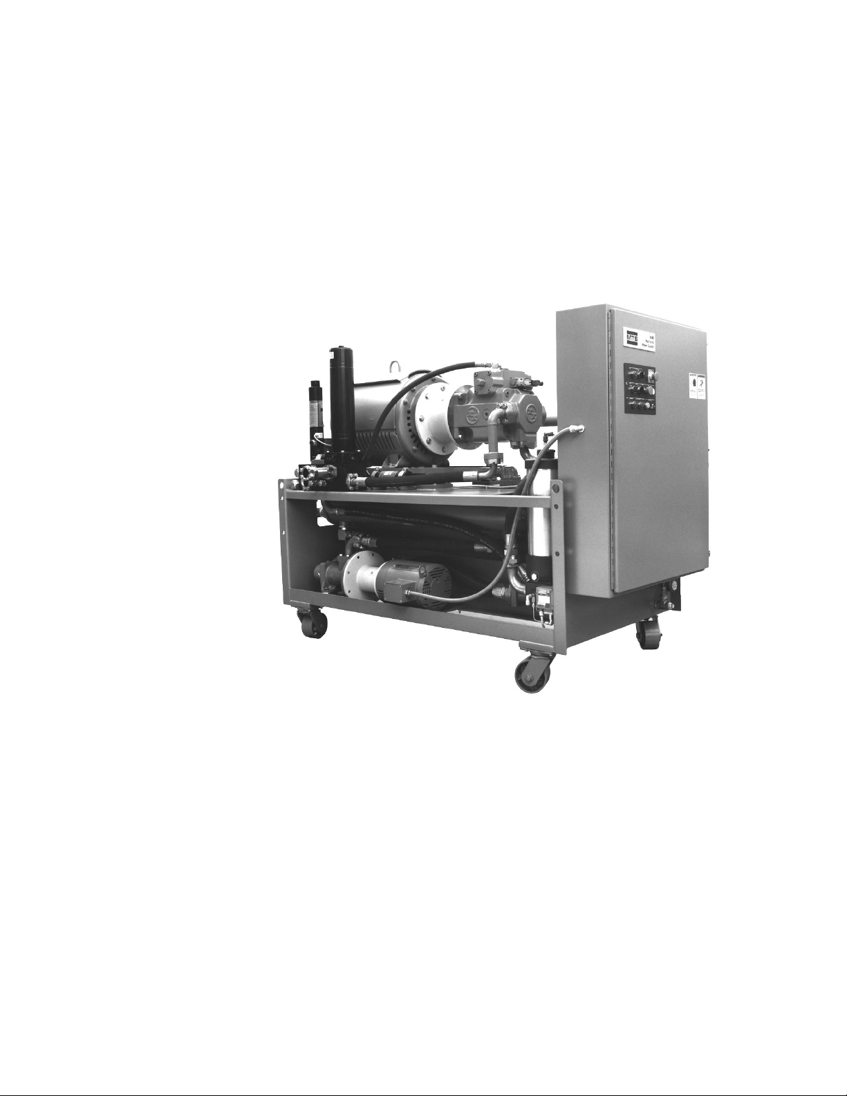
Definition The Model 506.62/.72 Hydraulic Power Supply (HPS) uses a variable-
volume (pressure compensated) main pump, with a pressurized
(supercharged) hydraulic fluid inlet, to provide pressure to systems
with various flow requirements. The HPS is designed to be used with
servo-controlled, electro-hydraulic systems.
1.1 Functional Description
Front panel controls
and indicators
Pressure output
Front panel controls on the HPS include local operating controls for the
main pump and supercharge pump. Front panel indicators show running
time, power on, low fluid level, fluid over-temperature, and dirty filter
conditions.
Pressure output is controlled by an adjustment on the main pump and is
monitored by the output pressure gage. An adjustable back-up relief
valve limits output pressure by porting fluid back to the reservoir when
the output pressure rises above the relief valve setting. High/low
pressure operation is controlled by the high/low solenoid valves.
These valves control the main pressure control (pressure compensator)
vent ports and the backup relief valve vent port.
019-341M
Introduction 1-1
Page 6

Pressure accumulation The pump-outlet pressure accumulator smooths the HPS output and
provides additional hydraulic pressure for high instantaneous flow
demands. It is precharged with dry nitrogen to a pressure proportional
to HPS output pressure. The optional slow turn-on accumulator slows
the rate at which the backup relief valve shifts from low to high
pressure.
Temperature control A temperature gage indicates hydraulic fluid temperature. An
oil-to-water heat exchanger controls the fluid temperature. When the
temperature exceeds a preset limit, a temperature sensitive switch
turns off the HPS and lights the front panel Fluid Over-Temperature
indicator.
Fluid level indication A transparent gage indicates the level of hydraulic fluid in the HPS
reservoir. A low-level switch automatically turns off the HPS and
lights the front panel Low Fluid Level indicator if hydraulic fluid
drops below a preset level.
Programmable logic
controller
The PLC (programmable logic controller) located in the starter
assembly performs logic functions. The I/O (input/output) section of the
PLC provides an interface for various signals received from or sent to
external devices.
1.2 Specifications
Cooling water
specifications
Cooling Water Inlet Required Water Flow
Temperature 506.62 506.72
60°F (15.5°C) 30 gpm (114 L/min) 35 gpm (132 L/min)
65°F (18.5°C) 35 gpm (132 l/min) 42 gpm (159 L/min)
70°F (21.0°C) 40 gpm (151 Ll/min) 51 gpm (193 L/min)
75°F (24.0°C) 40 gpm (151 L/min) 67 gpm (254 L/min)
The required water pressure between the input and the output of the
heat exchanger is 30 to 45 psi (0.2 to 0.3 MPa). The maximum allowable
pressure is 120 psi (0.8 MPa). The flow rate (±20%) at a given
temperature is shown in the table below.
Table 1-1. Cooling Water Requirements
1-2 Introduction
80°F (26.5°C) 45 gpm (170 L/min) 90 gpm (341 L/min)
85°F (29.5°C) 63 gpm (238 L/min) 120 gpm (454 L/min)
Page 7

HPS specifications Table 1-2 lists the specifications for the Model 506.62/.72 HPS.
Table 1-2. HPS Specifications
Parameter Model 506.62 Model 506.72
Maximum continuous pressure 3000 psi (21 MPa) 3000 psi (21 MPa)
Maximum flow capacity 75 gpm (284 L/min) 100 gpm (380 L/min)
Noise rating at 3 ft. (0.9 m) 90 dBa 90 dBa
Reservoir capacity: 200 gpm (757 L) 280 gpm (1074 L)
Low-pressure filtration, absolute/nominal 3.0/0.45 microns 3.0/0.45 microns
High-pressure filtration 10 microns 10 microns
Fluid hose connections:
*
Pressure (SAE 4 bolt) -20 (1), -24 (1) -20 (1), -24 (1)
Return (SAE 4 bolt) -20 (1), -24 (1) -20 (1), -24 (1)
Drain (37° flare) -12 (2), -16 (1) -12 (2), -16 (1)
Main pump motor power rating (2 each) 150 hp (112 kW) 200 hp (150 kW)
Supercharge pump motor power rating 15 hp (11 kW) 20 hp (15 kW)
3-phase current 460V/60 Hz:
†
Inrush 385 A 515 A
Conti nuous 200 A 250 A
Starter type (main pump motor) Wye-delta Wye-delta
24 V external hydraulic control amps, 60 Hz 9 A 9 A
Maximum cooling water heat load:
BTU per hour 380,000 509,000
Kilocalories per hour 96,000 128,600
Atmospheric heat load
BTU per hour 27,600 37,000
Kilocalories per hour 7,000 11,100
Water inlet/outlet size 1.25 in. (38.8 mm) I.D. 1.25 in. (38.8 mm) I.D.
Maximum ambient operating temperature 104°F (40°C) 104°F (40°C)
Minimum ambient operating temperature 40°F (4.4°C) 40°F (4.4°C)
Height with casters 68 in. (1727 mm) 78 in. (1981 mm)
Length 90 in. (2286 mm) 90 in. (2286 mm)
Width 45 in. (1143 mm) 45 in. (1143 mm)
Weight with oil 6000 lb (2722 kg) 6,500 lb (2948 kg)
* The number of connections are shown in parentheses.
†
Currents listed are typical values. Maximum values may be as much as 10 to 15% higher.
Specifications are subject to change without notice. Contact MTS for verification of any critical specifications.
Introduction 1-3
Page 8

Page 9
Section 2
Operation
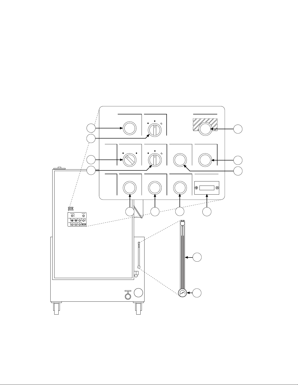
2.1 Controls and Indicators
The controls and indicators provided with the Model 506.62/.72
Hydraulic Power Supply (HPS) are described in Table 2-1. The
locations of these components are identified in the following figure.
Power
1
Spch Pump
Auto
Run
Start
Emergency Stop
11
2
HPS
Control
Source
Remote Local
Main Pump
High
Low
Stop
Start
3
4
Conditions Fluid Low Level
Fluid Over-Temp
65
Dirty Filter
7
Reset
10
9
Hours of Operation
8
Figure 2-1. Controls and Indicators
12
13
VW-G041C
Operation 2-1
Page 10

Table 2-1. Controls and Indicators
Item Control/Indicator Description
1 Power indicator* The Power indicator lights to indicate that electrical power is
applied to the HPS.
2 Spch Pump
Auto/Run/Start switch
To operate the supercharge pump when the main pump is not
operating, turn this spring-loaded switch to Start. After the
switch is released, it returns to the Run position — indicating
that the supercharge pump is circulating hydraulic fluid through
the heat exchanger and fine filter. If the switch is in the Auto
position, the HPS can be controlled by either the High/
Low/Start switch or the optional remote control panel.
3 Source Remote/Local
switch
If this two-position switch is in the Local position, you can
operate the HPS with the front panel controls. If it is in the
Remote position, use a remote control device to operate the HPS.
4 Main Pump
High/Low/Start switch
To apply low pressure in local control, turn this spring-loaded
switch to Start. After the switch is released, it returns to the
Low position — indicating low pressure operation. Turn the
switch to High to select high pressure.
5 Low Fluid Level
indicator*
6 Fluid Over-Temperature
indicator*
When this indicator lights, the hydraulic fluid level has
dropped below a preset value.
When this indicator lights, hydraulic fluid temperature has
exceeded a preset value.
7 Dirty Filter indicator* When this indicator lights, the low-pressure filter needs
replacement. See Subsection 3.1.1.
8 Hours of Operation
meter
This front panel meter indicates the total operating hours of the
pump.
9 Stop switch When Stop is pressed (in either local and remote control), the
HPS output first ramps to low pressure and then goes to zero
pressure. The supercharge pump continues to run for
approximately 10 seconds.
10 Reset switch This switch resets the interlock circuit if the condition causing
the interlock has been corrected.
11 Emergency Stop switch This switch operates in both local and remote control and is used
during emergency situations only. When pressed, it immediately
shuts down the HPS (the supercharge pump may continue to run
briefly to supply the main pump until they fully stop).
12 Fluid level gage This gage indicates the level of hydraulic fluid in the reservoir.
13 Temperature gage This gage indicates the temperature of the hydraulic fluid in the
HPS reservoir.
* Indicators are "push-to-test" type indicators. This means that if you push the indicator, it will light. If it does not light, the
bulb is burned out.
2-2 Operation
Page 11

2.2 Operation Procedures
WARNING
!
This section provides the local and remote operating procedures for the
506.62/.72 Hydraulic Power Supply.
Warning
Do not start the HPS if the servovalve command is not equal to
feedback (that is, zero balanced).
Failure to do this can result in sudden actuator movement which may
cause injury to persons and/or damage to equipment.
Ensure that the system is at zero balance before starting the HPS.
Before you begin Make sure that the external hydraulic system is ready for operation.
NOTE The Dirty Filter indicator may light during a cold-
start. It should turn off when the HPS reaches its
normal operating temperature. If the indicator fails to
turn off, correct the condition (Subsection 3.1.1.2) and
press Reset.
Local operation 1. Turn the Source Remote/Local switch to Local.
2. Apply electrical power to the HPS (the Power indicator will
light).
3. Press Reset.
1
4. Momentarily turn the High/Low/Start switch to Start. When you
release the switch, it returns to Low.
5. Check the HPS and external hydraulic system for leaks and
unusual sounds.
6. Turn the High/Low/Start switch to High to apply high pressure.
7. Press Stop on the HPS front panel to stop the HPS and remove
output pressure.
1
Reset must be pressed whenever electrical power to the HPS has been interrupted.
Operation 2-3
Page 12
Remote Operation
1. Turn the Source Remote/Local switch to Remote. Make sure that
the remote control cable is connected to the cable connector (the
figure on the left shows the location of this connector) and to the
remote control device.
2. Apply electrical power.
1
Remote control
connector
3. Press Reset.
4. Use the remote control device to start the HPS at low pressure.
5. Check for leaks and unusual sounds.
6. Select high pressure at the remote control device.
7. Use the Off switch on the remote control device to stop the HPS
and remove output pressure.
2.3 Supercharge Pump Operation
When the temperature of the hydraulic fluid in the HPS reservoir
When to use the
supercharge pump
Cooling procedure 1. Ensure the water supply to the heat exchanger is turned on.
exceeds 140˚F (60˚C), the fluid over-temperature switch automatically
shuts down the HPS. The HPS main pumps cannot be restarted in local
or remote until the hydraulic fluid cools. The following procedure uses
the supercharge pump to hasten the cooling of the hydraulic fluid.
2. Turn the Spch Pump switch to the Start position and then release
the switch and allow it to return to the Run position. The
supercharge pump operates independently of the main pumps and
circulates hydraulic fluid through the heat exchanger to cool the
fluid.
3. When the temperature gage reads approximately 130˚F (54˚C),
turn the Spch Pump switch to the Auto position (the supercharge
pump will stop).
4. To restart the HPS, first press the Reset control on the local or
remote control panel to clear the hydraulic interlock circuit, and
then start the HPS in low pressure.
1
Reset must be pressed whenever electrical power to the HPS has been interrupted.
2-4 Operation
Page 13
Section 3
9
Service
Introduction This section contains service information for the Model 506.62/.72
Hydraulic Power Supply (HPS). It provides:
• maintenance procedures
• service adjustments
• electrical information
3.1 Maintenance Procedures
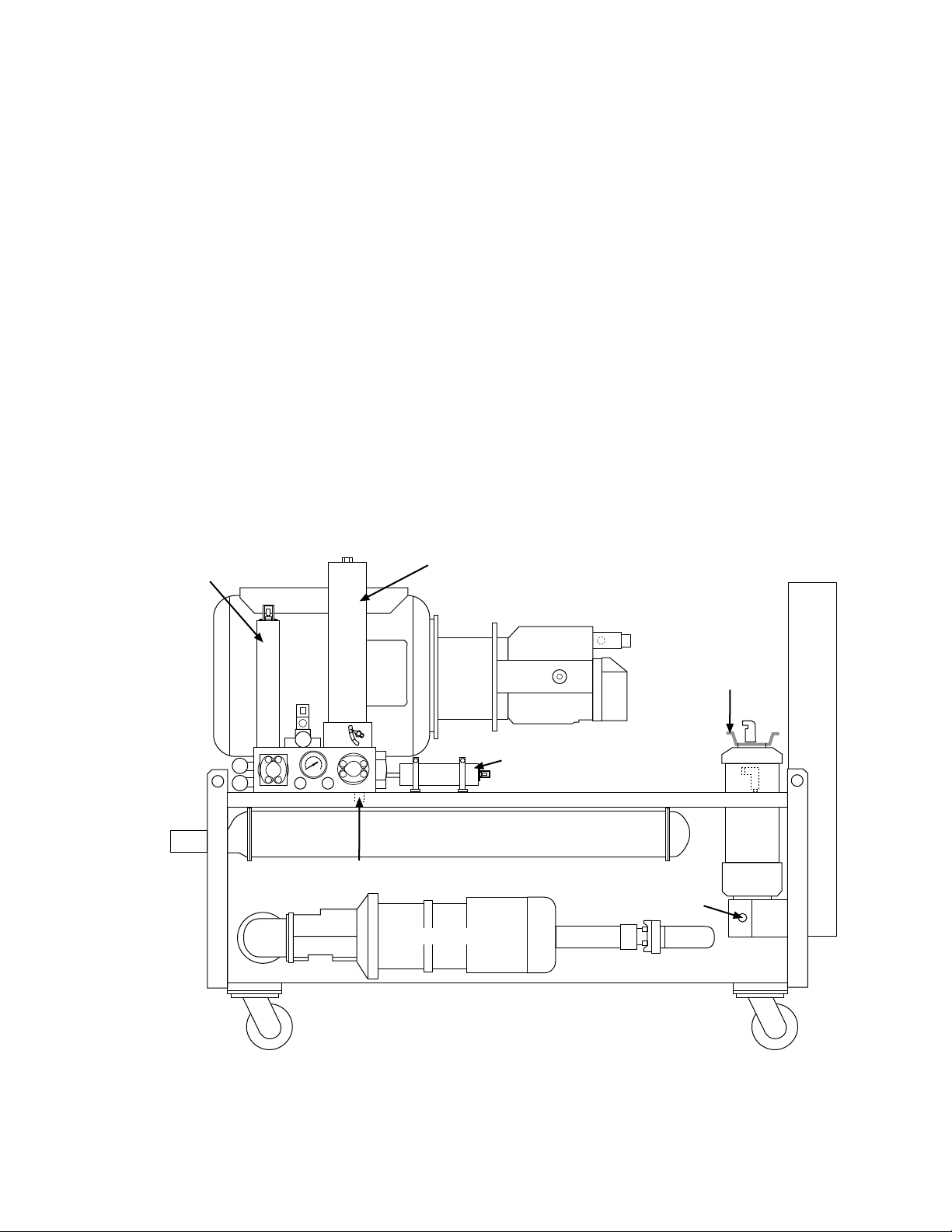
Maintenance overview The following subsections provide the routine maintenance procedures
for the HPS. Figure 3-1 shows the location of the components accessed
for the maintenance procedures. Table 3-1 lists the maintenance
schedule.
Pressure
Accumulator
High Pressure
Filter
Low Pressure
Filter
Slow Turn-on
Accumulator
Heat Exchanger
Manifold Drain
(under manifold)
Filter
Drain
Supercharge Pump
Figure 3-1. Location of Maintenance Components (HPS Side View)
VW-G06
Service 3-1
Page 14
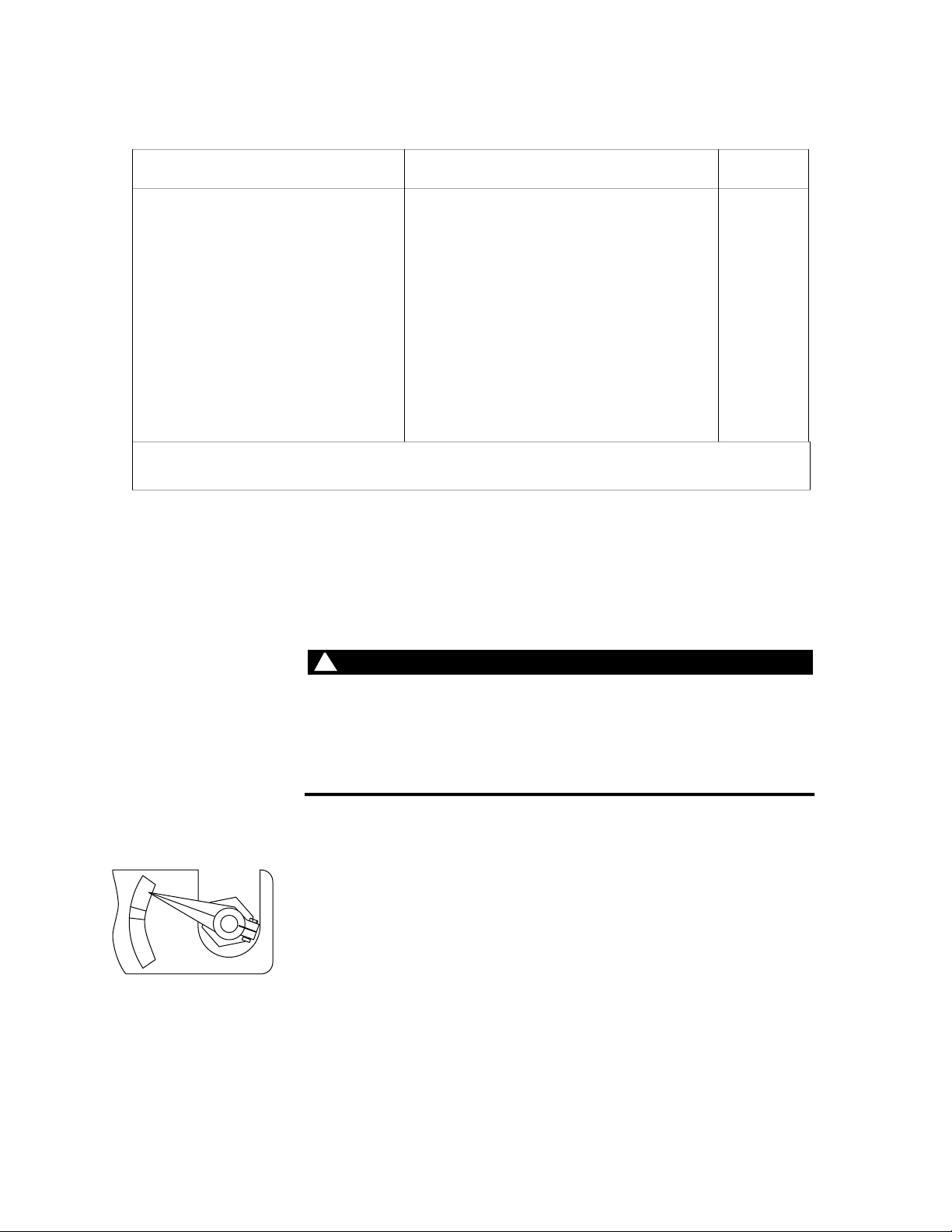
Table 3-1. Maintenance Schedule
WARNING
!
6
Procedure Interval Subsection
Check output pressure on gage* daily
Replace high-pressure filter when the indicator points to CHANGE 3.1.1
Replace low-pressure filter when Dirty Filter indicator lights 3.1.1
Check hydraulic fluid level on gage daily 3.1.2
Check hydraulic fluid in reservoir 150 operating hours 3.1.2
Analyze hydraulic fluid 500 operating hours 3.1.2
Check accumulator precharge at established interval 3.1.3
Check hydraulic hoses monthly
*
See Subsection 3.2.1 to adjust the output pressure.
3.1.1 Filters
Fluid filtration is provided by a 10-micron high-pressure filter and a
3-micron low-pressure filter. See Figure 3-1 for the location of the
filters and their drains.
High-pressure release occurs if the system is pressurized.
High-pressure release may cause personal injury or damage equipment.
Ensure that the output pressure gage reads zero before replacing the
filters.
3.1.1.1 High-Pressure Filter Replacement
CHANGE
Replace the high-pressure filter elements whenever the DIRT ALARM
indicator mounted on the base of each high-pressure filter housing
points to CHANGE (red or yellow zone) or whenever the hydraulic
OK
DIRT ALARM
VW-GO4
fluid is replaced.
1. Press Stop on the HPS. The output pressure gage must read zero.
3-2 Service
Page 15

End Cap – Top V iew
air-bleed
unscrews
screw
unscrews
endcap
2. Loosen the air-bleed screw on top of the filter housing endcap. See
the figure on the left.
3. With a container under the manifold drain port (Figure 3-1), open
the port to drain the fluid from the filter (the pressure
accumulator also drains).
4 When the fluid is drained, close the drain port and tighten the
air-bleed screw. Discard the fluid according to company policy.
VW-G047B
5. Unscrew and remove the endcap. Remove the compression spring
plate on top of the filter elements and remove the filter elements.
air-bleed
screw
endcap
6. Remove and save the grommet between the two filter elements.
O-ring
Discard the filter elements.
7. Inspect the O-ring and back-up washer in the end-cap. If
replacement is not required, clean and lubricate them with clean
hydraulic fluid.
filter
housing
8. Inspect the filter housing for any remaining contamination.
9. Insert two clean filter elements (MTS part number 100533-05), with
the grommet between the two elements, into the filter housing.
10. Inspect the compression spring plate and replace the end-cap.
base
VW-G070
Taking care not to damage the O-ring and the back-up washer,
tighten the end-cap.
After you have finished Operate the HPS in low pressure for 5 minutes to remove air from the
filter housing. Check for leaks while doing this.
Service 3-3
Page 16

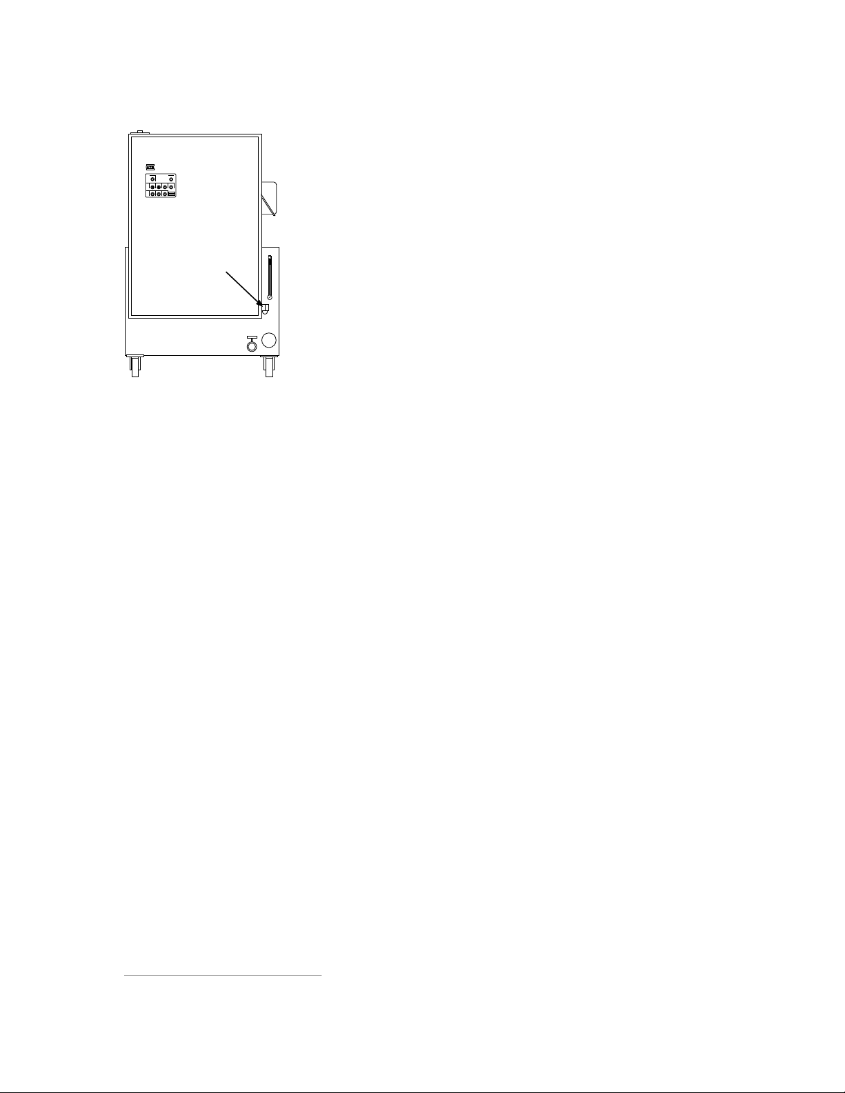
3.1.1.2 Low-Pressure Filter Replacement
The low-pressure filter element requires replacement whenever
hydraulic fluid in the HPS reservoir is replaced, or the Filter Dirty
indicator on the HPS front control panel lights.
See Figure 3-1 for the location of the filter. Refer to the figure on the
left to locate the components accessed for the following procedure.
1
Side View
cable
handle
1. Press Stop on the HPS. The output pressure gage must read zero.
2. Disconnect the cable from the filter cover.
3. Remove one of the two bleed screws at the top of the filter cover.
4. Place a container under the filter drain and drain the fluid.
bleed
screws
Dispose of the fluid according to company policy.
5. Replace and tighten the bleed screw and drain plug.
6. Hand turn the handle counterclockwise until it screws off. Remove
filter
housing
the cover.
7. Remove and discard the filter element. Inspect the filter housing
for any remaining contamination.
filter
drain
8. Insert a new filter element (MTS part number 114028-17).
9. Hand tighten the cover.
10. Reconnect the cable.
After you have finished Purge the filter housing of air and allow it to fill with fluid as follows:
1. Open the bleed screw 1-1/2 turns.
2. Press the Reset control to reset the Dirty Filter indicator.
3. Momentarily turn the Spch Pump switch to the Start position,
then immediately return it to Auto. Continue this procedure until
hydraulic fluid appears at the loosened bleed screw.
4. Close and tighten the bleed screw.
1
This indicator may light during a cold-start condition, but should extinguish when the HPS reaches its normal operating
temperature.
3-4 Service
Page 17

3.1.2 Hydraulic Fluid
Regular maintenance of hydraulic fluid maximizes the service life of
the system and its components.
Daily fluid checks Check the fluid-level in the transparent gage. A low level can indicate
a leak. A high level can indicate water contamination from the heat
exchanger. If the fluid appears to have changed significantly, obtain a
sample from the HPS reservoir and check it for the following qualities:
• Considerable darkness, burnt odor, or an opaque quality of the
fluid indicates chemical breakdown. It may also indicate that the
fluid temperature was too high. Replace the fluid.
• During operation, a milky appearance indicates water is present in
the fluid. If the system is not in operation, water separates from
the hydraulic fluid and settles at the bottom of the reservoir. If
water contamination is present, correct the source of the water
leakage and replace the hydraulic fluid.
Monthly fluid checks Perform these checks monthly or every 150 operating hours (whichever
comes first).
• Keep records of the maximum reservoir temperature. High
operating temperatures can cause the fluid to break down.
Yearly (every 500
operating hours) fluid
checks
• Check for contamination and fluid breakdown. Take a fluid sample
and test the pH level using a pH kit (available from chemical
stores). Also, check the sample for color and odor.
• Take a fluid sample and let it stand overnight. Sediment at the
bottom of the fluid indicates collapsed, ruptured or clogged filters.
Obtain a sample of the fluid and have it analyzed. The fluid tests
should include chemical analysis, particle count, and viscosity checks.
Record the results and replace the fluid if necessary.
Service 3-5
Page 18

Replacing hydraulic fluid Perform this procedure to replace the hydraulic fluid. You will need a
Front View
CAUTION
!
Model 590.01 Fluid Transfer Pump or a pump which provides at least
10-micron filtration.
1. Turn off electrical power to the HPS. Remove the reservoir filler
cap assembly.
2. Drain the hydraulic fluid into a container, while hot, through the
drain valve. Close the valve.
3. Then drain the oil from the entire system (such as from the hoses
and accumulators).
4. Dispose of the fluid according to company policy.
5. Remove the top plate from the reservoir.
6. Wipe the inside of the reservoir with a clean lint-free cloth.
Apply MOBILSOL A—a solvent for cleaning and flushing
hydraulic systems—to a clean lint-free cloth and again wipe the
reservoir. Immediately wipe away the solvent with a dry cloth.
Drain
VW-G041E
7. Replace the high-pressure filter element. See Subsection 3.1.1.1.
8. Replace the low-pressure filter element. See Subsection 3.1.1.2.
To avoid damage to the hydraulic system, follow these precautions:
Do not mix different brands of hydraulic fluid. This can create
contaminants. Ensure that the replacement hydraulic fluid is the same
brand and type as the fluid which was removed. Generally, an MTS
Hydraulic Power Supply contains Mobil DTE 25 hydraulic fluid.
Consult MTS before you use alternate fluids.
Use a transfer pump that provides 10-micron or better filtration. Most
commercial hydraulic fluids exceed the maximum amount of
contamination allowable in MTS hydraulic systems.
9. Use the transfer pump to fill the reservoir with fresh hydraulic
fluid.
10. To flush out the pipe line, connect a hose from the pressure line to
the return line of the last station, and operate the HPS at low
pressure for 2 - 4 hours.
11. Replace the high-pressure filter element if necessary (Subsection
3.1.1.1).
3-6 Service
Page 19

3.1.3 Accumulators
HPS – Side View
r
For more information
about accumulators
See the Series 111 Accumulator product manual(MTS part number
115533-XX). For other accumulators, refer to the vendor literature or
the Procedure for Checking Piston and Bladder Type Accumulator
Precharge and Precharging (MTS part number 408266-XX).
3.1.3.1 Precharge Pressure-Checking Intervals
Precharge pressure of the pressure accumulator must be checked at
regular intervals. To establish an interval time, follow this procedure:
1. Initially, check the precharge pressure after 2 weeks or 100
pressure
accumulato
operating hours.
2. If the pressure changes more than 200 psi, check the precharge
CHANGE
OK
DIRT ALARM
pressure every week or 50 operating hours.
If the pressure changes less than 200 psi, check the precharge
slow turn-on
accumulator
VW-G044J
pressure every four weeks or 200 operating hours.
Precharge pressure of the slow turn-on accumulator must be checked at
regular intervals. To establish an interval time, follow this procedure:
1. Initially, check the precharge pressure after 2 weeks or 100
operating hours.
2. If there is a pressure-level change of more than 50%, check the
precharge pressure every week or 50 operating hours.
If there is a pressure-level change of less than 50%, check the
precharge pressure every four weeks or 200 operating hours.
3.1.3.2 Precharging the Accumulators
If the pressure accumulator has a pressure-level change of ±200 psi
between checks, recharge it. If the slow turn-on accumulator has a
pressure-level change of ±50% between checks, recharge it.
The pressure and slow turn-on accumulators are typically precharged to
1000 psi (7 MPa) and 800 psi (5.5 MPa), respectively. These are the
recommended levels for an HPS output pressure of 3000 psi (21 MPa).
3.1.3.3 Changing the Accumulator Seals
When you have established a regular interval for checking the
precharge pressure, note the amount of pressure loss that occurs each
time the precharge pressure is checked. If an increase in pressure loss
occurs during the period between checks, the seals may require
replacement.
Service 3-7
Page 20

3.2 Service Adjustments
Service overview Figure 3-2 shows the location of the service components accessed for the
following procedures.
• output pressure adjustment
• dual-temperature switch adjustments
• low-level switch adjustment
• main pump low-inlet pressure switch adjustment
Pressure
control
Low level
switch
Back-up
relief valve
Heat Exchanger
Supercharge Pump
Low-inlet
pressure
switch
VW-G069B
Figure 3-2. Location of Adjustment Components (HPS Side View)
3-8 Service
Page 21
3.2.1 Output Pressure Adjustment
HPS – Side View
Top View
t
Refer to Figure 3-2 for the location of the components indicated in the
following procedure.
1. Turn off the HPS.
back-up
relief valve
CHANGE
OK
DIRT ALARM
2. Make sure that the output pressure gage reads zero (the figure on
the left shows the location of the pressure gage).
pressure
gage
VW-G044K
3. Remove the plastic cap on the pump pressure control.
4. Loosen the locknut and turn the pressure control fully
counterclockwise.
5. Loosen the locknut on the back-up relief valve and turn the
adjustment knob fully counterclockwise.
Locknut
Backup relief valve
Adjustmen
knob
TS-G072
6. Start the HPS in low pressure, then switch to high pressure.
7. Observe the pressure gage and alternately turn the back-up relief
valve adjustment and the pressure control knob clockwise.
1
Stop adjusting at approximately 500 psi (3.45 MPa) above the
desired output pressure (typically 3000 psi/21 MPa).
8. Tighten the locknut on the back-up relief valve.
9. Turn the pressure control adjustment knob counterclockwise until
the desired output pressure is reached.
10. Turn off the HPS and replace the plastic cap removed in step 3.
NOTE Whenever the output pressure is changed, the
accumulator precharge must also be checked (see
Subsection 3.1.3).
1
Adjustment increments should be approximately 500 psi (3.45 MPa) apart as indicated on the pressure gage.
Service 3-9
Page 22

3.2.2 Dual-Temperature Switch Adjustments
F
s
Definition The dual-temperature switch has two adjustment screws behind its
front protective cover. The Over Temperature adjustment turns off the
HPS if hydraulic fluid reaches a temperature of 140˚F (60˚C). The
Water Control adjustment is set at 115° F (43 °C). It controls water flow
through the heat exchanger.
Front view without cover
Adjustment
screws
Side
screw
Dual-temperature
switch
Before you begin Turn off the HPS. Loosen the screws on each side of the switch
assembly, and pull the front protective cover off. The adjustment screws
are labelled OT for over-temperature and WC for water control.
VW-G042
Over-temperature
adjustment
NOTE The fluid-level and temperature gage on the HPS is
used for reference only. Use a laboratory grade
thermometer to set the temperature switches in the
following procedure.
1. Turn the over-temperature adjustment screw (figure above) several
turns clockwise to raise the temperature limit.
2. Turn off the water supply to disable the heat exchanger.
3. Turn on the HPS and apply high pressure (see Subsection 2.2).
4. When hydraulic fluid temperature reaches 140˚F (60˚C), as
indicated on the temperature gage, turn the adjusting screw
counterclockwise until the HPS turns off.
5. Turn on the cooling water supply.
3-10 Service
Page 23

Water control
1
1. Ensure that the temperature gage reads below 90°F (32°C).
adjustment
2. Start the HPS. Turn the water control adjustment screw (figure
above) fully counterclockwise.
3. Monitor the temperature gage while the hydraulic fluid
temperature rises.
4. When the fluid temperature reaches approximately 110°F (43°C),
turn the adjustment screw clockwise until water starts to flow, then
turn it counterclockwise until water flow stops.
5. If the fluid temperature does not reach 115°F (46°C) turn the screw
a half-turn counterclockwise and note the effect after 15 minutes.
If the temperature exceeds 115°F (46°C), turn the screw clockwise.
3.2.3 Low-Level Switch Adjustment
The low fluid-level switch turns off the HPS if there is an appreciable
loss of hydraulic fluid. The factory-adjustment coincides with the
bottom of the fluid level gage and does not normally require
readjustment. Perform the following steps if readjustment is necessary.
locknut
top of
reservoir
VW-G05
1. With the HPS turned off, fill the reservoir to the correct fluid
level.
2. Turn on the HPS and apply high pressure.
3. See the figure on the left. Loosen the hand locknut on the stem of
the switch, and slowly raise the switch until the Low Fluid Level
indicator lights.
4. Lower the switch about 1.5 in. (38 mm).
5. Tighten the locknut.
6. Reset any applicable interlock circuits.
Service 3-11
Page 24

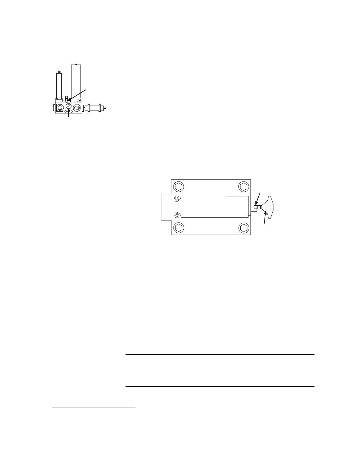
3.2.4 Main Pump Low-Inlet Pressure Switch Adjustment
Pressure Switch
(cover removed)
Adjustment knob
Indicator
Figure 3-2 shows the location of the main pump low-inlet-pressure
switch on the HPS. The switch monitors the pressure level supplied by
the supercharge pump at the input to the main pump. The switch
protects the main pump by turning off the HPS if the supercharge pump
pressure drops below the minimum level required by the main pump.
The switch is set at the factory to activate at 15 psi (0.1 MPa). This
switch may be adjusted with or without the HPS running. Use the
following procedure to adjust the switch.
1. Remove the four screws holding the cover and check the position of
the indicator.
2. If the indicator does not point to approximately 15 psi (0.1 MPa),
turn the adjustment knob located on top of the switch to increase or
decrease the pressure setting to 15 psi (0.1 MPa).
3. Re-install the cover and four screws.
VW-G052
3-12 Service
Page 25

3.3 Starter Assembly
WARNING
!
4
The starter assembly (Figure 3-3 shows the location of its components)
is located behind the starter box door. This section provides the
following information:
• Abnormal HPS Shutdown
• Fuse Replacement
• PLC (programmable logic controller) Service
WARNING
High voltage is present in the starter assembly. Do not open the starter
box door when power is applied to the HPS.
Touching components with high voltage can cause death.
Remove electrical power at the power disconnect switch before you open
the front starter box door.
Master control
relay
Programmable
logic controller
SPCH pump fuses
1FU
2FU
1M
SPCH
starter
Transformer
3FU
2M
Main
pump
starter
4FU
7FU
6FU
ground
Main pump fuses
8FU
3M 1S
5FU
Earth
9FU
Input power
10FU
PLC terminal block
Overload
relays
TS-G07
Figure 3-3. Model 506.62/.72 Starter Assembly
Service 3-13
Page 26

3.3.1 Abnormal HPS Shutdown
WARNING
!
Motor overload Sudden shutdown of the HPS may be due to circuit protection elements
in the pump motor starter assembly. If the supercharge motor
overloads, the relay opens and de-energizes the motor starter coils to
shut down the HPS. If the pump motor overloads, the pump shuts
down.
Reset procedure If a motor overloads, follow this procedure to reset it.
1. Turn off ac power at the HPS disconnect switch.
High voltage is present in the starter assembly if power is not removed.
Failure to remove power before opening the HPS starter box door may
cause death or injury.
Remove electrical power at the power disconnect switch.
2. Open the starter box door and locate the appropriate motor
overload relay (Figure 3-3).
3. Press the reset button located on the relay to enable operation.
NOTE The overload relay element may be equipped with a
3.3.2 Fuse Replacement
Table 3-2 lists the fuse values and part numbers of the fuses located in
the starter assembly. Figure 3-3 shows the location of the fuses.
switch to provide manual or automatic reset. This
switch should always be set to the manual position.
Table 3-2. Starter Assembly Fuse Values
Fuses Type MTS PN
FU 1 through FU 3 30A slo-blo 100725-05
FU 4 and FU 5 3A slo-blo 111457-06
FU 6 6A slo-blo 100524-27
FU 7 4A slo-blo 100524-04
FU 8 through FU 10 250A slo-blo 100725-52
3-14 Service
Page 27

3.3.3 PLC Service
The PLC in the 506.62/.72 HPS starter assembly has output and input
indicators shown in the figure below. These indicators are described in
the following tables.
0109 0110 0111 COM
Output indicators
(channel 1)
OUTPUT 1CH
0 1 2 3 4 5 6 7
8 9 10 11
POWER
RUN
ALARM
ERROR
Input indicators
(channel 0)
0 1 2 3 4 5 6 7
8 9 10 11 12 13 14 15
NC NC
506.62/.72 Output Indicators
Output Indicator CH1 Description
0 Remote low-level interlock/indication.
1 Remote over-temperature interlock/indication.
2 Remote dirty filter interlock/indication.
3 Remote run indication.
4 Turns on to energize main pump motor start control relay 1CR.
5 Turns on to energize main pump motor run control relay 2CR.
6 Turns on to energize main high-pressure solenoid 1SOL.
7 Turns on to energize water inlet solenoid 2SOL that allows water flow
into the heat exchanger for cooling hydraulic fluid.
8
Turns on to light front panel Low Fluid Level indicator 2LT.
0CHINPUT
24VDC 0.3A
+
VW-G073
9 Turns on to light front panel Fluid Over Temperature indicator 3LT.
10 Turns on to light front panel Dirty Filter indicator 4LT.
11 Turns on to energize supercharge motor starter 1M
Service 3-15
Page 28

506.62/.72 Input Indicators
Input Indicator CH0 Description
0 Turns off if switch 2TAS (115°F) opens. When fluid temperature exceeds a
preset limit, 2TAS opens to energize water inlet solenoid 2SOL. 2SOL
controls the water valve allowing water into the heat exchanger to cool
the fluid. (If Input 0 is off and input 13 is on, then output 7 is on.)
1 Turns off if ∆P switch 2PS (35 psi) opens to indicate the fine filter is dirty.
2 Turns on momentarily if the Remote/Local start switch is pressed.
3 Turns on if the pump is running or ready to run. Momentary "low" will shut
pump off it it is running.
4 Turns on if the front panel Main Pump High/Low/Start switch is turned to
High or high pressure is selected with a remote switch.
5 Turns on if the front panel Remote/Local switch is turned to Local.
6 Turns on if the front panel Reset switch is pressed.
7 Turns off if switch 1FS opens to indicate that the fluid level has dropped
below a preset limit.
8 Turns off if switch 1TAS (140°F) opens to indicate that the hydraulic fluid
temperature has exceeded a preset limit.
9 Turns off if motor overload relay contact 2 OL or 1 OL opens to indicate
that the supercharge or pump motor is drawing excessive current.
10 Turns on if the front panel Spch Pump switch is turned to Start. The
supercharge pump continues to run until the Spch Pump switch is turned to
Auto (i.e. if indicator 11 goes off).
11 Turns off if the front panel Spch Pump switch is turned to Auto.
12 Turns on if inlet pressure switch 1PS (15 psi) closes to start the main pump.
Inlet pressure is supplied by the supercharge pump
13 Turns on if motor relay contacts 1M close to indicate the supercharge pump
is running.
14 Turns on if motor relay contacts 3M close to indicate the main pump motor is
running.
15 Turns off if the E-Stop switch is pressed.
3-16 Service
Page 29

Section 4
Installation
Introduction This section provides the following installation information for the
Model 506.62/.72 Hydraulic Power Supply (HPS).
• hydraulic connections
• electrical connections
• water connections
Before you complete
connections
Perform these steps before you make any connections to the HPS.
1. Remove the shipping plate located under the hydraulic fluid
filler cap.
2. Make sure that the chained jumper plug is connected to the remote
control connector located on the side of the starter box door. See
the figure below.
Remote control
connector
For remote control
connection
Figure 4-1. Location of Remote Control Connector
The jumper plug may be replaced by the system cable from a remote
control device when the HPS is ready for system operation.
Installation 4-1
Page 30

4.1 Hydraulic Connections
HPS – Side View
L
The pressure, return and drain connections are located on the HPS
manifold shown in Figure 4-2. Refer to the system hydraulic
distribution drawing in the Assembly Drawings system reference
manual for hydraulic connections that are specific to your system.
Hydraulic connections Hydraulic hose connections from the HPS are made to the ports
labelled P (pressure) and R (return) on the HPS manifold. These
connections are typically made to a system servovalve manifold,
hydraulic service manifold, or hydraulic distribution manifold. The
HPS has drain ports for any drainback connections used by the system.
Pressure
ports
Return
ports
Drain
ports
VW-G044
Figure 4-2. Hydraulic Connections
NOTE Table 1-2 shows the specifications for the ports shown
in Figure 4-2.
4-2 Installation
Page 31

4.2 Electrical Connections
WARNING
!
4
The HPS is operated from a three-phase electrical power source. The
operating voltage is labeled on the outside of the starter assembly and
on the pump motor.
Before you begin
Install a fused power disconnect switch (customer supplied). This
switch removes electrical power to the HPS. Local codes dictate the
type of switch to be used. Electrical connections must be made by
qualified personnel and conform to local codes and regulations.
When the electrical connections have been made, high voltage is
present in the starter assembly when power is on. Do not open the
starter box door with power applied to the HPS.
Touching components with high voltage can cause death.
Remove electrical power at the power disconnect switch before you open
the front starter box door.
Master control
relay
Programmable
logic controller
SPCH pump fuses
1FU
2FU
1M
SPCH
starter
Transformer
3FU
2M
Main
pump
starter
4FU
7FU
6FU
ground
Main pump fuses
8FU
3M 1S
5FU
Earth
9FU
Input power
10FU
PLC terminal block
Overload
relays
Figure 4-3. Model 506.62/.72 Starter Assembly
Installation 4-3
TS-G07
Page 32

4.2.1 Transformer Wiring
460 Vac
230 Vac
6
One of two types of transformers is installed in the starter assembly.
Check the wiring configuration of the transformer before applying ac
power to the HPS.
Standard transformer
wiring
H1
X2
H3
Optional transformer
wiring
This figure shows the jumper wiring required on a standard transformer
for source voltages of 460 and 230 Vac.
jumper
H2
H4 H1
X1
X2
jumper
H3
jumper
H2
Figure 4-4. Standard Transformer Wiring Configuration
An optional multi-tap transformer may be used for source voltages other
than 230 Vac and 460 Vac. The following figure shows the typical
wiring required for various voltages. Source voltages are applied to
terminals H1 through H5 as shown. An output voltage is tapped from
terminals X1 through X4. Check the output voltage with a voltmeter.
It should be 110 Vac for systems using 50 Hz power and 115 to 120 Vac for
systems with 60 Hz.
H4
X1
VW-C03
208/220/230/240 Vac
380/400/416 Vac
440/460/480 Vac
500/550/575/600 Vac
Figure 4-5. Typical Multi-Tap Transformer Wiring Configuration
4-4 Installation
X4
H3H2H1
X3 X2 X1
H4
H5
110/120/125/130 Vac
100/110/115/120 Vac
85/91/99 Vac
VW-C037
Page 33

4.2.2 Input Power
WARNING
!
Electrical connection
procedure
Polarity check Perform this procedure to ensure that electrical power is properly
See Figure 4-3 and perform the following procedure to make the
electrical connections.
1. Connect a solid earth ground from the power disconnect switch to
the starter assembly.
2. Connect the three input leads from the disconnect switch to the
three terminals located on the starter assembly.
3. Close starter box.
connected to the HPS:
1. Apply ac power to the HPS. The Power indicator should light.
2. Jog the supercharge pump motor by turning the Spch Pump switch
to Run and then immediately returning it to the Auto position.
High voltage is present in the starter box if power is not removed.
Failure to remove power before opening the starter box may cause death
or injury.
Remove electrical power at the power disconnect switch.
3. If the supercharge motor is rotating in the direction indicated by
the arrow on the pump motor housing, electrical connections are
correct. If it is rotating in the opposite direction of the arrow,
remove ac power to the HPS and switch two of the three input
power leads to the HPS (refer to Figure 4-3).
Installation 4-5
Page 34

4.3 Cooling Water Connections
t
Shut-off
Specifications The differential pressure required between the water inlet and outlet
connections is 30 to 45 psi (0.2 to 0.3 MPa). The maximum allowable
water pressure is 120 psi (0.83 MPa). The water supply must be capable
of providing water flow at a rate indicated in Table 1-1. See Table 1-2
for the maximum cooling water heat load.
Water connections Use a 1.5 in. (38 mm) water service hose to connect the water supply and
drain to the heat exchanger water inlet and outlet connections (figure
below).
Heat Exchanger – Top View
hot fluid (from
supercharge pump)
cold fluid (to low
pressure filter)
valve
water in
water ou
VW-G055B
4-6 Installation
Page 35

Theory of Operation
This section describes the hydraulic and electrical operation of Model
506.62/.72 Hydraulic Power Supply (HPS).
5.1 Hydraulic Operation
The figure below shows a block diagram of the HPS hydraulic operation.
Section 5
Low-Inlet
Pressure
1PS
Filter Pressure
In
ER
Out
compensator
Switch
Switch 2 PS
Fluid-Level and
Temperature
Gage
Pressure
-20 JIC
M
Main Pump
set
at 3025 psi
35
psi
Optional
Water
Control
Valve
M
Pressure
-24 4 Bolt
High-Pressure
Filter
10-micron
Check
Valve
1 Sol
Low-Pressure
Fine Filter
3-micron
Heat
Exchanger
Supercharge
Pump
Output
Pressure
Gage
Filter
Bypass
Pressure
Accumulator
Bleed-down
2 SOL
24 Vdc
Supercharge and
Filter Manifold
Supercharge
Relief Valve
preset to crack
at 30 psi
Water-Control
Valve Temperature
Switch
set at 115° rising
3500 psi
Orifice
Over-Temperature
set at 140° rising
Figure 5-1. Hydraulic Block Diagram
Back-up
Relief Valve
Slow Turn-on
Accumulator
Main Manifold
Assembly
Switch
Return
-20 JIC
Low-Level
Float
Switch
Return
-24 4 Bolt
Drain
-16 JIC
-12 JIC
-12 JIC
TS-C133B
Theory of Operation 5-1
Page 36

Main and supercharge
pumps
Filters Hydraulic fluid from the low-pressure filter is routed to the main
Back-up relief valve An adjustable back-up relief valve limits output pressure by porting
High/low solenoid valve High/low pressure operation is controlled by the high/low solenoid
The HPS uses a variable-volume pressure compensated main pump,
with a pressurized (supercharged) hydraulic fluid inlet to provide
fluid flow. The supercharge pump draws hydraulic fluid from the
reservoir and forces it through a heat exchanger and a low-pressure
filter. Fluid not required by the main pump returns to the reservoir
through check valves in the low-pressure filter manifold.
pump. A low-inlet pressure switch monitors the inlet pressure
(supercharge output pressure) to the main pump.
Fluid from the main pump outlet passes through a check valve and a
10-micron high-pressure filter. The output pressure is controlled by the
pressure compensator adjustment on the main pump and is monitored by
the output pressure gage. Output volume varies automatically with
external circuit demand.
fluid back to the reservoir. When the pump compensator is operating
normally, the relief valve does not open.
valve. This valve controls the backup relief valve vent port.
With the high/low solenoid valve de-energized, the back-up relief
valve vent port is open and output volume is ported to the reservoir,
limiting output pressure to approximately 150 psi (1.03 MPa). This
low-pressure condition occurs during supply turn-on for low pressure
start-up and during power-up of the HPS.
With the high/low solenoid valve energized, the vent port is blocked
and system pressure can rise to the preset operating pressure, typically
3000 psi (21 MPa).
Fluid temperature Hydraulic fluid temperature is maintained at a recommended
operating level by a fluid-to-water heat exchanger which passes the
fluid over water-filled tubes. Water flow through the tubes is
automatically regulated by a solenoid valve which is controlled by a
programmable logic controller (PLC). If fluid temperature exceeds a
preset limit (typically 140°F), a temperature-sensitive switch turns the
HPS off.
The fluid level and temperature gage on the HPS is used for reference
only. Use a laboratory grade thermometer to set the temperature.
5-2 Theory of Operation
Page 37

Pump protection Pump protection is provided for the main pump by the main pump
low-inlet pressure switch that turns the supply off if supercharge
pressure drops below the recommended operating pressure. The
supercharge pump and main pump are protected by a fluid-level
switch, which turns the supply off if the level of hydraulic fluid in the
reservoir drops below a preset level.
Pressure accumulation The pump-outlet pressure accumulator smooths the HPS output and
provides additional hydraulic pressure for high instantaneous flow
demands. It is precharged with dry nitrogen to a pressure proportional
to HPS output pressure. The optional slow turn-on accumulator slows
the rate at which the backup relief valve shifts from low to high
pressure. The precharge must be adjusted proportionally to the HPS
output pressure. If it is above or below the recommended level, the
effect of the accumulator is reduced.
5.2 Electrical Operation
This section provides the HPS electrical theory of the operation.
Figure 5-2 is a typical electrical schematic for the 506.62/.72 HPS.
HPS operation is controlled by a PLC (programmable logic controller).
It is designed so that a desired circuit in relay ladder logic can be
programmed. The PLC provides logic functions previously
accomplished by relays, timers and sequencers. It contains an I/O
section that receives input data from various switches and contacts that
are hardwired to the input terminals. The PLC sends output commands
to motors, motor starters, solenoid valves and indicator lights that are
hardwired to the output terminals. The PLC operating program is
retained by an EPROM memory module. A back-up battery is not
required.
5.2.1 Control
When the disconnect switch is closed, the HPS control panel Power On
indicator lights to show that electrical power to the HPS is on.
Inlet pressure When the High/Low/Start switch is positioned to Start, relay 1M at
PLC output 111 energizes to start the supercharge motor. Contacts 1M
provide the supercharge motor status to PLC input 013. The
supercharge motor provides inlet pressure for the main pump. When
the inlet pressure is reached (typically 15 psi), pressure switch 1PS
(connected from the outlet of the supercharge pump to PLC input 012)
closes to start the pump motor.
Start control The start signal is sent to input 002 of the PLC. If various conditions
(such as interlocks) are satisfied, the start signal is routed to output 104
of the PLC to energize the main pump motor start control relay (1CR).
Theory of Operation 5-3
Page 38

Pump motor When 1CR contacts close, the main pump motor starts, using a
Wye-delta start. First relay 1S energizes to close 1S contacts and
energize relay 2M (1M contacts close). Relays 2M and 1S provide a wye
connection (this reduces inrush current) to start the main pump motor.
After a timing delay that the PLC provides, output 105 energizes relay
2CR. The state of all 2CR contacts change to de-energize 1S and
energize 3M. Relays 2M and 3M connect the motor windings in a delta
configuration to provide full current to the motor. A set of 3M contacts
provides the motor status to the PLC at input 014.
High pressure When the HPS High/Low/Start switch is positioned to High, high
pressure is selected by energizing high-pressure solenoid 1 SOL for the
main pump.
Stop control When stop switch 1PB at PLC input 003 is pressed, the main pump
motor is turned off. The supercharge pump motor, however, continues to
run for approximately 10 seconds.
Emergency stop control Pressing Emergency Stop turns off the HPS by de-energizing relay CRM.
CRM contacts open to cut off power to the motor starter. The
supercharge pump may continue to run briefly while the main pump
winds down.
24 Vdc operation The HPS includes a 24 Vdc electrical power supply for operating
solenoid valves, relays and the PLC. Current available for external use
is listed in the specifications table. All solenoid valves connected to
this supply must be rated at 24 Vdc. If the 115 Vac control voltage
option is required, all solenoid valves connected to the supply must also
be rated at 115 Vac.
5-4 Theory of Operation
Page 39

5.2.2 Interlocks
The HPS contains interlock circuitry to shut down the HPS when
various conditions occur—such as low level hydraulic fluid, overtemperature, low pressure, dirty filters and motor overload.
Reset When the interlock condition has been corrected and the HPS is
restarted, Reset switch 2PB at PLC input 006 must be pressed to reset
the interlock circuitry.
Low-level hydraulic fluid Low fluid level switch 1FS protects the HPS if there is an appreciable
loss of hydraulic fluid. Whenever the level of hydraulic fluid in the
HPS reservoir drops below a preset limit, switch 1FS (at PLC input 007)
opens to turn off the pump motor, and disable the supercharge pump if it
is in the Start/Run mode. PLC output 100 generates the interlock. PLC
output 108 lights the Low Fluid Level indicator on the HPS front panel.
Fluid over-temperature
condition
Low-inlet pressure Pressure switch 1PS protects the main pump if inlet pressure drops
Water control valve
temperature switch
Dirty filter The low-pressure fine filter is monitored by ∆P switch 2PS (at PLC
Whenever the temperature of the hydraulic fluid in the HPS reservoir
exceeds a preset limit, switch 1TAS (at PLC input 008) opens to turn off
the HPS pump motor. The supercharge pump can be operated in the
Start/Run mode to cool the fluid. PLC output 101 generates the
interlock. PLC output 109 lights the Fluid Over-Temperature indicator
on the HPS front panel.
below the minimum level required by the main pumps. Switch 1PS (at
PLC input 012) closes whenever low-inlet pressure drops below a preset
limit (typically 50 psi). Closing 1PS while the pump motor is
operating, turns off the HPS. The supercharge pump, however, can be
operated in the Start/Run mode.
Whenever the temperature of the hydraulic fluid exceeds a preset
limit, switch 2TAS (at PLC input 000) opens to energize water-inlet
solenoid 2SOL (at PLC output 107). This solenoid controls the water
valve allowing water into the heat exchanger to cool the hydraulic
fluid.
input 001). When a dirty filter creates excessive differential pressure
across the filter, switch 2PS opens. PLC output 102 generates the
interlock. PLC output 110 lights the Dirty Filter indicator on the HPS
front panel. If the indicator is active when the HPS shutdowns, Reset
must be pressed (after the filter is replaced) to restart the HPS.
Motor overload Thermal overload sensors detect excessive current and open the
normally closed contacts connected to the motor starter coil. Motor
overload relay contacts 1OL and 2OL at PLC input 009 open to turn off
the HPS off if the supercharge or main pump motor draws excessive
current. When an overload condition occurs, the reset button on the
motor overload relay must be pressed (see Subsection 3.3.1).
Theory of Operation 5-5
Page 40

supplied by customer
must be grounded
disconnect switches
NOTE Hydraulic power supplies are often customized for
specific applications. Actual wiring may differ from
what is shown in Figure 5-2.
The wiring schematic that is specific to your system can
be found in the product information kit. This kit is
located inside the starter box.
2OL
2M
2OL
2M
2OL
2M
3M
3M
3M
2S 2S 2S
H3 H2
H1
X1 X2
8FU
9FU
10FU
4FU
5FU
H4
HPS
2MTR
6FU7FU
1CR 2M
1S 2CR
2CR
1S
3M
1HM
red
115 – 230 Vac
115 Vac neutral
Chassis Ground
A
L
D
24 Vdc
M
CRM
white
green
E-Stop
2M
3M
1S
CRM
1LT
R
mechanical
interlock
power on
motor 1 starter
motor 1 run contactor
motor 1 start contactor
motor 1 hour meter
PLC
master control relay
1FU
2FU
3FU
1M
1M
1M
1OL
1OL
1OL
Spch
1MTR
24 Vdc
to
outputs
24 Vdc
inputs
15 Vac
1
to
to
outputs
5-6 Theory of Operation
to
PLC
input 015
to
dc
common
to
ac
common
E
Figure 5-2. Typical Electrical Schematic
Balloon with letter indicates MS connector pin
VW-C039A
VW-C039A
Page 41

from
E-stop
B
K
H
E
24 Vdc
Set at 100ºF
35 PSI
remote/local
4SS
2PB
1 TAS
2 OL
50 PSI
1M
3M
2 TAS
2 PS
low
high
start
1SS
1 FS
set at 140°F (60°C)
start
auto run
3SS
1PS
1 OL
stop
1PB
PLC inputs
0000
0001
0002
0003
0004
0005
0006
0007
0008
0009
0010
0011
0012
0013
0014
0015
common
open water valve
fine filter
common
remote start
pump run
remote/
high pressure
remote/local
reset
fluid level
fluid temperature
motor overload
spch auto
spch only
inlet pressure
spch motor status
motor 1 status
E-stop
common
dc
F
24 Vdc
115 Vac
PLC outputs
0100
0101
0102
0103
0104
0105
0106
0107
0108
0109
0110
0111
common
common
common
common
1CR
common
common
2CR
1 SOL
2 SOL
R
R
A
1M
dc
common
low level
J
over-temp
G
filter dirty
N
B
HPS on
motor 1 start relay
motor 1 run relay
main hi press sol
water inlet sol
ac common
low level interlock
over-temp interlock
dirty filter warning
supercharge motor starter
Note:
Balloon with letter indicates MS connector pin
E
Figure 5-2. Typical Electrical Schematic (Continued)
VW-C039D
Theory of Operation 5-7
Page 42

Page 43

Page 44

m
MTS Systems Corporation
14000 Technology Drive
Eden Prairie, Minnesota 55344-2290 USA
Toll Free Phone: 800-328-2255
(within the U.S. or Canada)
Phone: 952-937-4000
(outside the U.S. or Canada)
Fax: 952-937-4515
E-mail: info@mts.com
http://www.mts.com
ISO 9001:2000 Certified QMS
 Loading...