

Page 1

be certain.
m
Series 505 SilentFlo™ Hydraulic Power Unit
Product Information
Model 505.60
Model 505.90
Model 505.120
Model 505.150
Model 505.180
100-006-453 U
Page 2

Copyright information © 1999–2010 MTS Systems Corporation. All rights reserved.
Trademark information MTS and SilentFlo are registered trademarks of MTS Systems Corporation
within the United States. These trademarks may be protected in other countries.
DTE is a registered trademark of Exxon Mobil Corporation.
Tellus is a registered trademark of Shell Oil Corporation.
Synasol is a registered trademark of Union Carbide Corporation.
Molykote is a registered trademark of Dow Chemical Corporation.
Publication information
MANUAL PART NUMBER PUBLICATION DATE
100-006-453 A October 1999
100-006-453 B January 2000
100-006-453 C September 2000
100-006-453 D January 2001
100-006-453 E April 2001
100-006-453 F September 2001
100-006-453 G January 2002
100-006-453 H July 2002
100-006-453 I June 2003
100-006-453 J May 2004
100-006-453 K September 2004
100-006-453 L August 2005
100-006-453 M June 2006
100-006-453 N August 2006
100-006-453 P September 2006
100-006-453 R February 2007
100-006-453 S March 2008
100-006-453 T April 2009
100-006-453 U March 2010
Page 3

Contents
Technical Support 7
How to Get Technical Support 7
Before You Contact MTS 7
If You Contact MTS by Phone 9
Problem Submittal Form in MTS Manuals 10
Preface 11
Before You Begin 11
Conventions 12
Documentation Conventions 12
Introduction 15
EU Declarations 15
Model 505.60 HPU Component Identification 16
HPU Functional Description 18
Options Available for the HPU 18
Model 505.60/.90 HPU Hydraulic Schematic 20
Model 505.120/.150/.180 HPU Hydraulic Schematic 21
Model 505.60 HPU Electrical Control 22
Model 505.60/.90 Electrical Schematic 23
Model 505.120/.150/.180 Electrical Schematic 26
Specifications 32
Model 505.60–505.180 HPU General Specifications 32
Model 505.60 HPU Specifications 33
Model 505.90 HPU Specifications 34
Model 505.120 HPU Specifications 35
Model 505.150 HPU Specifications 36
Model 505.180 HPU Specifications 37
Safety 39
General Safety Practices: Hydraulic Power Units and Hydraulic Service Manifolds 39
Hazard Placard Placement 45
Model 505.60 - 505.180 SilentFlo™ HPU Contents
3
Page 4

Installation 47
Model 505.60—505.180 HPU Electrical, Hydraulic, and Water Connections 47
Model 505.60 HPU Setup 52
Testing Model 505.60 HPU Operation 56
Precharging the Optional Surge Suppressor Accumulator 59
Operation 63
Model 505.60 HPU Startup Panel 64
Model 505.60 HPU Main Display 66
Model 505.60 HPU Data 68
Model 505.60 HPU Status 69
Model 505.60 HPU Setup 70
ROD Setup 72
Operating the Model 505.60 HPU Locally or Remotely 74
Recovering From an Interlock 76
Changing the Water Flow 78
Resetting the Thermal Overloads 79
Adjusting the Model 505.60 Hydraulic Pressure 81
Low/High Pressure Functionality 83
Setting Up Run-On-Demand 85
Maintenance 87
Routine Maintenance Overview Checklist 88
Models 505.60/.90/.120/.150/.180 HPU Maintenance Schedule 90
Checking the Hydraulic Fluid 92
Checking the Low Level/Temperature Detector 93
Replacing the Return-line Filter 94
Clamp-Style Housing Filter Replacement 94
Capscrew-Style Housing Filter Replacement 96
Replacing the Optional High-Pressure Filter 97
Sampling the Hydraulic Fluid 99
Replacing the Hydraulic Fluid 101
Inspecting the Heat Exchanger 103
Hydraulic Power Unit Maintenance and Service Logs 105
8 Hours/Daily 106
40 Hours/Weekly 107
4
Contents
Model 505.60 - 505.180 SilentFlo™ HPU
Page 5

160 Hours/Biweekly 108
500 Hours 109
1000 Hours 110
2000 Hours 111
5000 Hours 112
10,000 Hours 113
Model 505.60 - 505.180 SilentFlo™ HPU Contents
5
Page 6

6
Contents
Model 505.60 - 505.180 SilentFlo™ HPU
Page 7

Technical Support
How to Get Technical Support
How to Get Technical Support
Start with your
manuals
Technical support
methods
The manuals supplied by MTS provide most of the information you need to use
and maintain your equipment. If your equipment includes software, look for
online help and README files that contain additional product inform ation.
If you cannot find answers to your technical questions from these sources, you
can use the Internet, e-mail, telephone, or fax to contact MTS for assistance.
MTS provides a full range of support services after your system is installed. If
you have any questions about a system or product, contact Technical Support in
one of the following ways.
www.mts.com The web site provides access to our technical support staff by means of an
onlineform:
www.mts.com > Contact MTS > Service & Technical Support button
E-mail tech.support@mts.com
Telephone MTS Call Center 800-328-2255
Weekdays 7:00 A.M. to 5:00 P.M., Central Time
Fax 952-937-4515
Please include “Technical Support” in the subject line.
Outside the U.S. For technical support outside the United States, contact your local sales and
service office. For a list of worldwide sales and service locations and contact
information, use the Global MTS link at the MTS web site:
www.mts.com > Global MTS > (choose your region in the right-hand
column) > (choose the location closest to you)
Before You Contact MTS
MTS can help you more efficiently if you have the following information
available when you contact us for support.
Know your site
number and system
number
Model 505.60 - 505.180 SilentFlo™ HPU Technical Support
The site number contains your company number and identifies your equipment
type (such as material testing or simulation). The number is typically written on a
label on your equipment before the system leaves MTS. If you do not know your
MTS site number, contact your sales engineer.
Example site number: 571167
When you have more than one MTS system, the system job number identifies
your system. You can find your job number in your order paperwork.
Example system number: US1.42460
7
Page 8

Before You Contact MTS
Know information from
prior technical
If you have contacted MTS about this problem before, we can recall your file
based on the:
assistance
• MTS notification number
• Name of the person who helped you
Identify the problem Describe the problem and know the answers to the following questions:
• How long and how often has the problem occurred?
• Can you reproduce the problem?
• Were any hardware or software changes made to the system before the
problem started?
• What are the equipment model numbers?
• What is the controller model (if applicable)?
• What is the system configuration?
Know relevant
For a computer problem, have the following information available:
computer information
• Manufacturer’s name and model number
• Operating software type and service patch information
Know relevant
software information
• Amount of system memory
• Amount of free space on the hard drive where the application resides
• Current status of hard-drive fragmentation
• Connection status to a corporate network
For software application problems, have the following information available:
• The software application’s name, version number, build number, and (if
available) software patch number. This information can typically be found
in the About selection in the Help menu.
• The names of other applications on your computer, such as:
– Anti-virus software
– Screen savers
– Keyboard enhancers
– Print spoolers
– Messaging applications
Technical Supp ort
8
Model 505.60 - 505.180 SilentFlo™ HPU
Page 9

If You Contact MTS by Phone
If You Contact MTS by Phone
A Call Center agent registers your call before connecting you with a technical
support specialist. The agent asks you for your:
• Site number
• Name
• Company name
• Company address
• Phone number where you can be reached
If your issue has a notification number, please provide that number. A new issue
will be assigned a unique notification number.
Identify system type To enable the Call Center agent to connect you with the most qualified technical
support specialist available, identify your system as one of the following types:
• Electromechanical material test system
• Hydromechanical material test system
Be prepared to
troubleshoot
Write down relevant
information
After you call MTS logs and tracks all calls to ensure that you receive assistance for your
• Vehicle test system
• Vehicle component test system
• Aero test system
Prepare to perform troubleshooting while on the phone:
• Call from a telephone close to the system so that you can implement
suggestions made over the phone.
• Have the original operating and application software media available.
• If you are not familiar with all aspects of the equipment operation, have an
experienced user nearby to assist you.
In case Technical Support must call you:
• Verify the notification number.
• Record the name of the person who helped you.
• Write down any specific instructions.
problem or request. If you have questions about the status of your problem or
have additional information to report, please contact Technical Support again and
provide your original notification number.
Model 505.60 - 505.180 SilentFlo™ HPU Technical Support
9
Page 10

Problem Submittal Form in MTS Manuals
Problem Submittal Form in MTS Manuals
Use the Problem Submittal Form to communicate problems with your software,
hardware, manuals, or service that are not resolved to your satisfaction through
the technical support process. The form includes check boxes that allow you to
indicate the urgency of your problem and your expectation of an acceptable
response time. We guarantee a timely response—your feedback is important to
us.
Access the Problem Submittal Form:
• In the back of many MTS manuals (postage paid form to be mailed to MTS)
• www.mts.com > Contact Us > Problem Submittal Form button (electronic
form to be e-mailed to MTS)
Technical Supp ort
10
Model 505.60 - 505.180 SilentFlo™ HPU
Page 11

Before You Begin
Preface
Before You Begin
Safety first! Before you use your MTS product or system, read and understand the Safety
manual and any other safety information provided with your system. Improper
installation, operation, or maintenance can result in hazardous conditions that can
cause severe personal injury or death, or damage to your equipment and
specimen. Again, read and understand the safety information provided with your
system before you continue. It is very important that you remain aware of
hazards that apply to your system.
Other MTS manuals In addition to this manual, you may receive additional manuals in paper or
electronic form.
You may also receive an MTS System Documentation CD. It contains an
electronic copy of the manuals that pertain to your test system, such as:
• Hydraulic and mechanical component manuals
• Assembly drawings
• Parts lists
• Operation manual
• Preventive maintenance manual
Controller and application software manuals are typically included on the
software CD distribution disc(s).
Model 505.60 - 505.180 SilentFlo™ HPU Preface
11
Page 12

Conventions
DANGER
WARNING
CAUTION
Conventions
Documentation Conventions
The following paragraphs describe some of the conventions that are used in your
MTS manuals.
Hazard conventions Hazard notices may be embedded in this manual. These notices contain safety
information that is specific to the activity to be performed. Hazard notices
immediately precede the step or procedure that may lead to an associated hazard.
Read all hazard notices carefully and follow all directions and recommendations.
Three different levels of hazard notices may appear in your manuals. Following
are examples of all three levels.
Note For general safety information, see the safety information provided with
your system.
Danger notices indicate the presence of a hazard with a high level of risk which,
if ignored, will result in death, severe personal injury, or substantial property
damage.
Warning notices indicate the presence of a hazard with a medium level of risk
which, if ignored, can result in death, severe personal injury, or substantial
property damage.
Caution notices indicate the presence of a hazard with a low level of risk which,
if ignored, could cause moderate or minor personal injury or equipment damage,
or could endanger test integrity.
Notes Notes provide additional information about operating your system or highlight
easily overlooked items. For example:
Note Resources that are put back on the hardware lists show up at the end of
the list.
Special terms The first occurrence of special terms is shown in italics.
Illustrations Illustrations appear in this manual to clarify text. They are examples only and do
not necessarily represent your actual system configuration, test application, or
software.
Electronic manual
conventions
This manual is available as an electronic document in the Portable Document
File (PDF) format. It can be viewed on any computer that has Adobe Acrobat
Reader installed.
12
Preface
Model 505.60 - 505.180 SilentFlo™ HPU
Page 13

Documentation Conventions
Hypertext links The electronic document has many hypertext links displayed in a blue font. All
blue words in the body text, along with all contents entries and index page
numbers, are hypertext links. When you click a hypertext link, the application
jumps to the corresponding topic.
Model 505.60 - 505.180 SilentFlo™ HPU Preface
13
Page 14

Documentation Conventions
14
Preface
Model 505.60 - 505.180 SilentFlo™ HPU
Page 15
Introduction
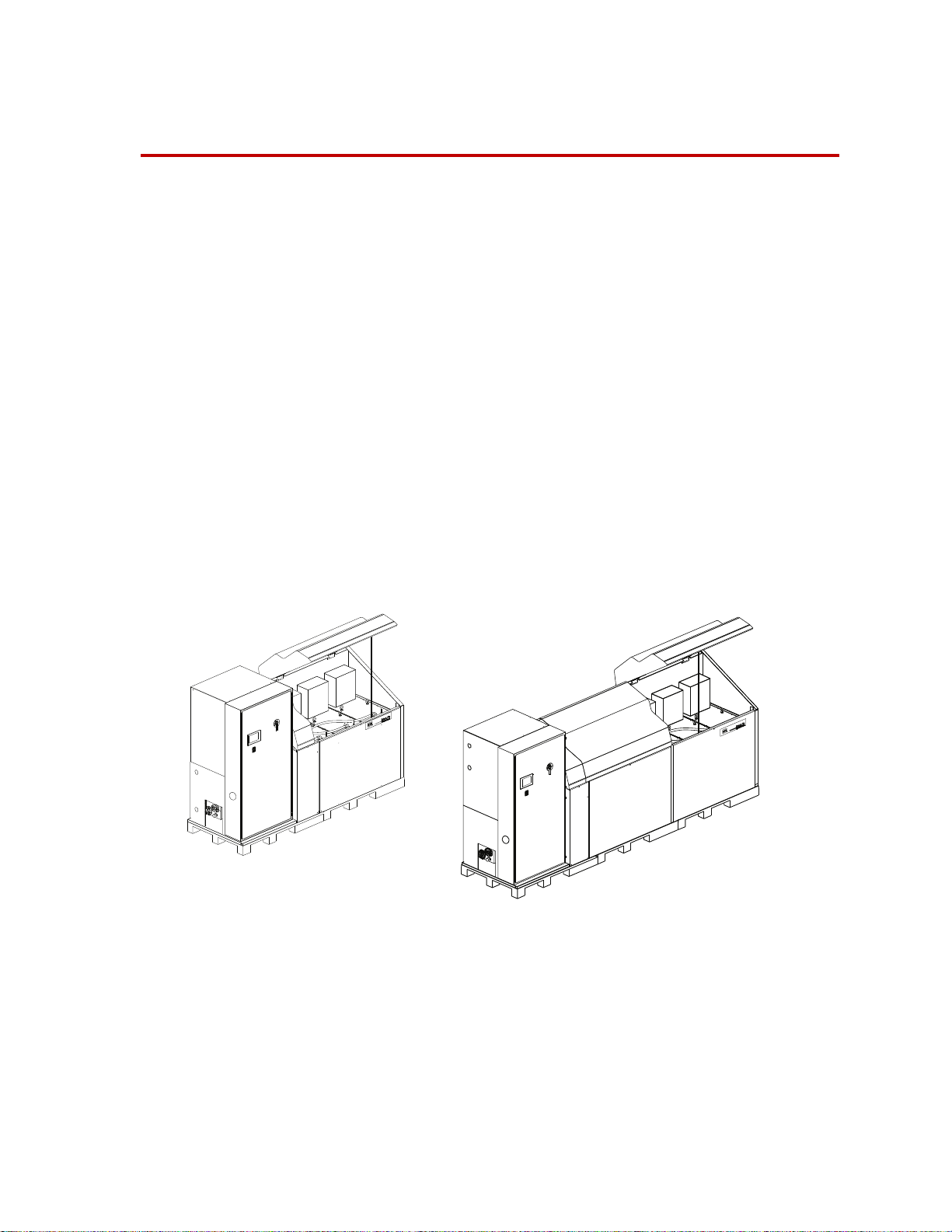
Models 505.60/.90 HPU
Models 505.120/.150/.180 HPU
Contents Model 505.60 HPU Component Identification 16
EU Declarations
HPU Functional Description 18
Options Available for the HPU 18
Model 505.60/.90 HPU Hydraulic Schematic 20
Model 505.120/.150/.180 HPU Hydraulic Schematic 21
Model 505.60 HPU Electrical Control 22
Model 505.60/.90 Electrical Schematic 23
Model 505.120/.150/.180 Electrical Schematic 26
Model 505.60–505.180 HPU General Specifications 32
Model 505.60 HPU Specifications 33
Model 505.90 HPU Specifications 34
EU Declarations
Model 505.120 HPU Specifications 35
Model 505.150 HPU Specifications 36
Model 505.180 HPU Specifications 37
Model 505.60 - 505.180 SilentFlo™ HPU Introduction
EC Declaration of
Conformity (Machinery
Directive 2006/42/EC
Annex II 1A)
If applicable, a Declaration of Conformity is supplied with the machinery; an
example of the Declaration of Conformity is provided at the end of this manual.
15
Page 16
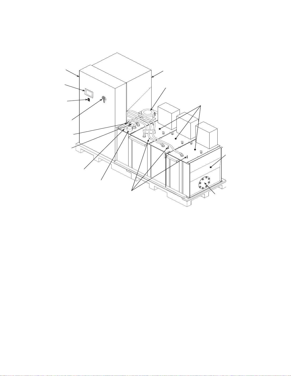
Model 505.60 HPU Component Identification
Heat Exchanger and
Manifold Enclosure
Filter Assembly
Pump
Assemblies
Reservoir
Output
Pressure
Controls
Filler Cap
Fluid Level Gage
Level/Temperature
Transducer
Level/Temperature
Switch
Power
Disconnect
Switch
Emergency
Stop Switch
User
Interface
Panel
Main
Electrical
Enclosure
Commoning
Expansion Plate
Model 505.60 HPU Component Identification
16
Introduction
Component Locations (505.90 Shown)
Model 505.60 - 505.180 SilentFlo™ HPU
Page 17

Model 505.60 HPU Component Identification
Component Descriptions
Component Description
Commoning Expansion
Plate
Electrical Enclosure
Filler Cap
Filter
Fluid Level Gage
Heat Exchanger
Level/Temperature
Transducer
Low Level/Temperature
Switch
Manifold
Allows the HPU to be commoned with another HPU.
Houses the HPU’s electrical and control components. The wye-delta starters
for the Model 505.60/.90 HPUs are located in the electrical enclosure. The
wye-delta starters for the Model 505.120/.150/.180 HPUs are located in the
pump assemblies. The main power lines enter the electrical enclosure at its top.
The power disconnect switch removes electrical power whenever the
enclosure’s door is opened.
Vents the hydraulic fluid reservoir. This is where you add hydraulic fluid.
Filters particles out of the hydraulic fluid as it is returned to the HPU.
Indicates the reservoir hydraulic fluid level.
Cools the hydraulic fluid using a highly efficient, stainless steel oil-to-water
heat exchanger. The heat exchanger removes most of the heat generated by the
HPU.
Senses the hydraulic fluid level and temperature, and produces an analog
signal for display purposes.
Senses the hydraulic fluid level and temperature. Control interlocks
automatically shut the HPU down if the fluid level drops too low or the
hydraulic fluid temperature rises above the sensor’s setting.
Combines the output of the individual pumps to deliver the full output of the
HPU through a single port. The manifold provides solenoid control of the high/
low pressure output from the individual pumps. It also contains relief valves
for each pump circuit and a bypass circuit to maintain the hydraulic
temperature during low flow conditions.
Output Pressure Controls
Power Disconnect Switch
Sets the output pressure of each pump assembly .
Disconnects the incoming power from the HPU. The switch is a lockable,
mechanical latch. Power is removed whenever the door to the electrical
enclosure is open. The switch will not allow the door to be opened when in the
ON (|) position. Incoming power lines to the switch are live unless power is
removed externally.
Pump Assemblies
Produces the pressurized hydraulic fluid for system use. Each pump assembly
includes a motor, pump, and electrical enclosure for connecting with the main
starter.
Reservoir
User Interface Panel
Holds the hydraulic fluid and houses the pump and motor.
Configures and controls the operation of the hydraulic power unit and indicates
the current status of several sensors.
Model 505.60 - 505.180 SilentFlo™ HPU Introduction
17
Page 18

HPU Functional Description
HPU Functional Description
Pump assemblies Pump assemblies draw hydraulic fluid from the reservoir and pressurize it to a
maximum preset pressure. Each pump assembly contains a variable volume
pump, a motor, and an electrical enclosure. Each pump assembly has a flow
capacity that contributes to the total hydraulic flow capacity of the HPU.
Manifold The manifold combines the pressurized hydraulic output of the discrete pump
assemblies, and provides the hydraulic connection to your hydraulic system. The
manifold contains the high/low pressure solenoid valve and a nonadjustable relief
valve. Check valves are located within the manifold to prevent pressurized
hydraulic fluid from being forced back through the pumps.
The hydraulic power unit uses solenoid-operated valves to control when highpressure is available to the hydraulic circuit. Start/low/high control settings are
selected at the operator interface on the electrical enclosure’s front panel.
The HPU is designed to start in low pressure to reduce the amperage needed for
starting, which will extend the life of the pump and motor. When operating at this
setting, low-pressure hydraulic fluid circulates back to the reservoir through the
manifold. The direct fluid path back to the reservoir limits pressure and flow
available out to the external hydraulic circuit. When high pressure is selected, the
unit forces pressurized hydraulic fluid out to the hydraulic circuit.
Filtering As hydraulic fluid returns to the reservoir, it is filtered by a full flow element.
This ensures that all hydraulic fluid is filtered, whether it travels out through the
circuit or returns by way of the unit’s manifold under low pressure. Filter
cleanliness is automatically monitored. A warning registered on the unit’s
operator interface signals when the filter needs to be changed.
Heat exchanger Hydraulic fluid temperature is maintained with a high–efficiency stainless steel
heat exchanger that cools the fluid. A regulating valve monitors the temperature
of the hydraulic fluid and adjusts the flow of water through the plates. The flow
of cooling water regulates the temperature of the hydraulic fluid. If the hydraulic
fluid temperature exceeds the maximum preset temperature, a switch opens and
shuts down the HPU. When the HPU is shut off, the flow of water is
automatically stopped by a shutoff solenoid valve.
Options Available for the HPU
Accumulator option Accumulators can be added to the hydraulic output lines to damp pressure line
fluctuations. This option accommodates one pressure line accumulator.
Run-on-demand option The run-on-demand (ROD) option will turn individual pumps on and off as
needed to accommodate the system’s demand for hydraulic fluid. The PLC
monitors the fluid flow; when flow changes beyond preset limits for a preset
time, a pump will be turned on or off as needed.
18
Introduction
Model 505.60 - 505.180 SilentFlo™ HPU
Page 19

Options Available for the HPU
The ROD option allows the HPU to turn individual pump motors on and off as
your system flow demand changes. A minimum flow reserve is maintained and
pump usage is equalized by sequentially turning on pumps starting with the
pump with the least amount of run time, and turning the pumps off in reverse
order. The cycling of these pumps is controlled by a PLC that takes into account
various system parameters such as system hydraulic fluid flow (both real time
and trends), the number of pumps currently running, and user configurable on/off
delay settings.
Model 505.60 - 505.180 SilentFlo™ HPU Introduction
19
Page 20
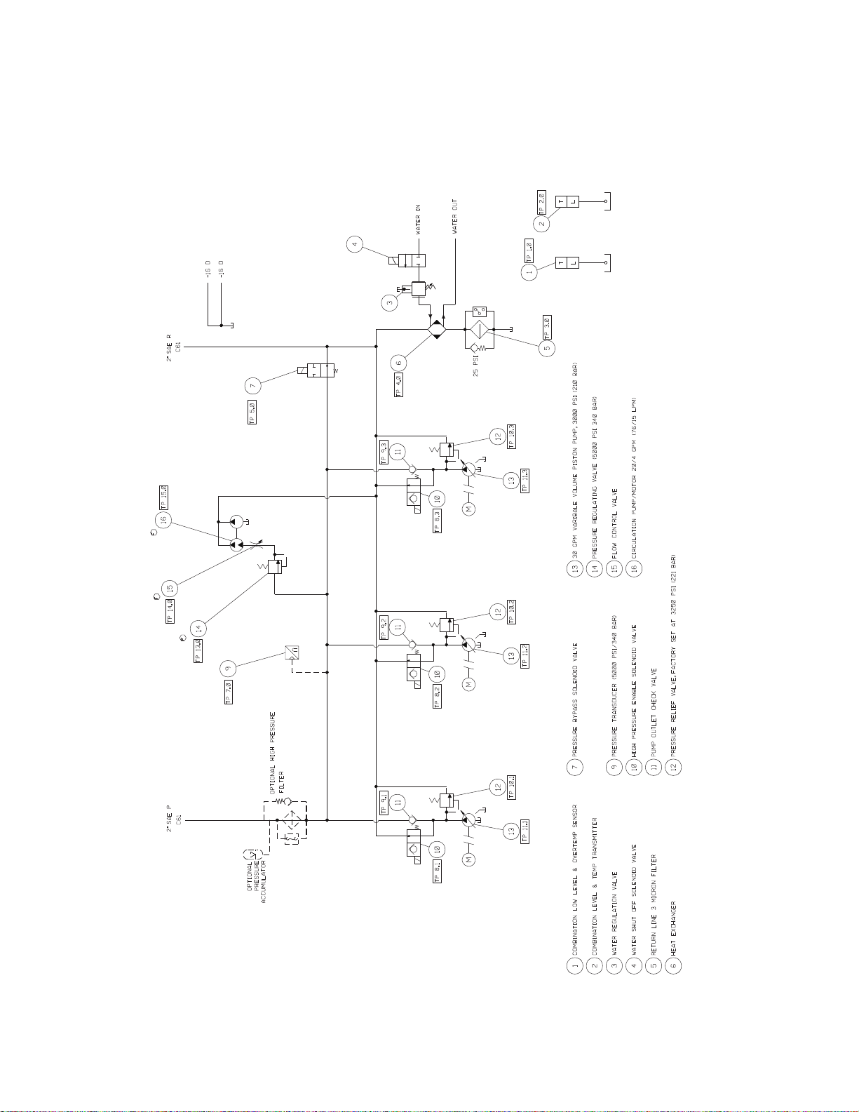
Model 505.60/.90 HPU Hydraulic Schematic
Model 505.60/.90 HPU Hydraulic Schematic
The hydraulic schematic shows the functional layout of HPU models with two or
three pump assemblies (505.60/.90).
20
Introduction
Model 505.60 - 505.180 SilentFlo™ HPU
Page 21
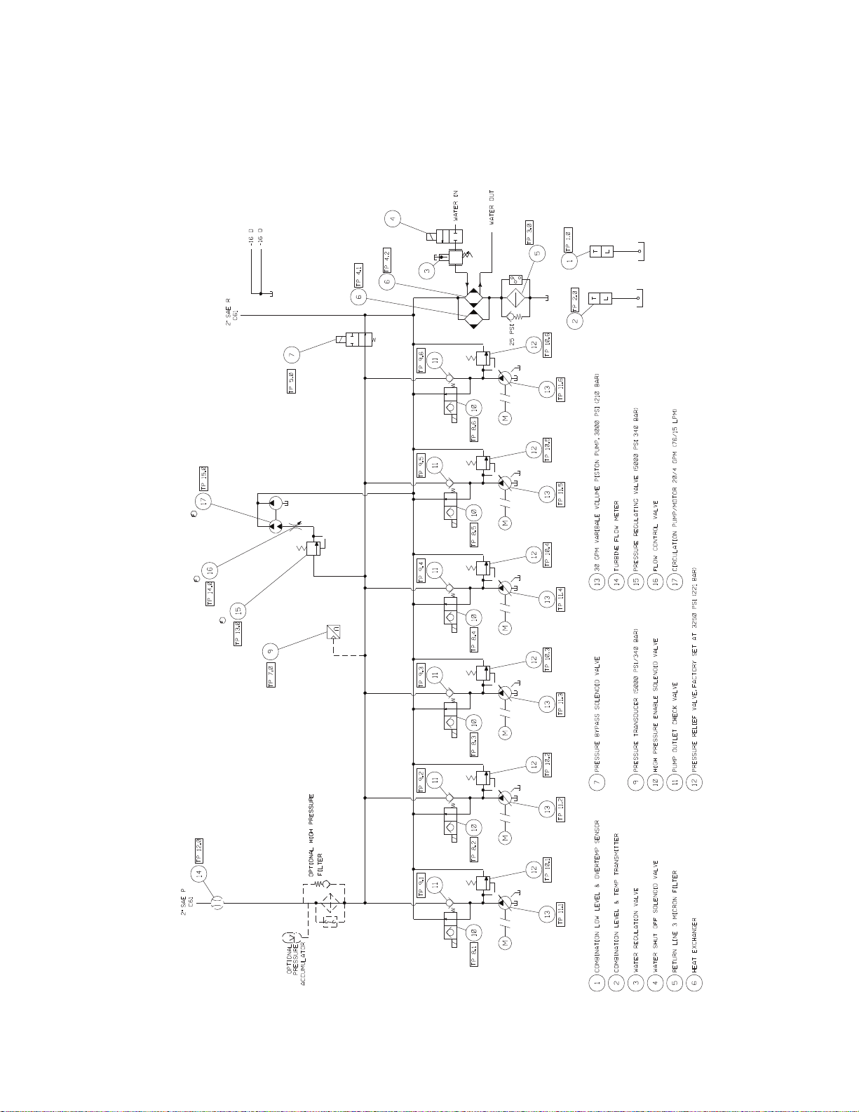
Model 505.120/.150/.180 HPU Hydraulic Schematic
Model 505.120/.150/.180 HPU Hydraulic Schematic
The hydraulic schematic shows the functional layout of HPU models with four to
six pump assemblies (505.120/.150/.180).
Model 505.60 - 505.180 SilentFlo™ HPU Introduction
21
Page 22

Model 505.60 HPU Electrical Control
Model 505.60 HPU Electrical Control
The HPU can be controlled locally using the front panel controls, or remotely
through a controller via the J1 connector . A PLC (programmable logic controller)
manages the electrical systems within the HPU. The electrical system includes
the following:
• A user interface panel that contains a touch screen to program preferences
and operational settings. The screens on the user interface panel provide
quick indication of the unit’s condition, including motors status, running
time displays for each motor, hydraulic fluid level and temperature, and
filter condition.
• Wye-delta starting reduces the initial current rush when the motor starters
are engaged.
• Thermal overloads protect the individual HPU motors from excessive
current draw .
• A latchable Emergency Stop button prevents inadvertent starts.
• Interlocks protect the HPU against low hydraulic fluid level,
overtemperature, and dirty filters.
• A Reset button brings the unit back into operation after a fault has been
detected and corrected.
• A dirty filter signal will not shut the unit down, but will prevent the unit
from starting.
• The power disconnect switch on the door of the main electrical enclosure
ensures that power is removed whenever the door is opened. This device is
both an ETL and TÜV-certified, lockable, main-disconnect switch.
Note The electrical schematics for the HPU are located on the following
pages. The difference between the Model 505.60/.90 and Model
505.120-180 is the number of pump assemblies.
22
Introduction
Model 505.60 - 505.180 SilentFlo™ HPU
Page 23
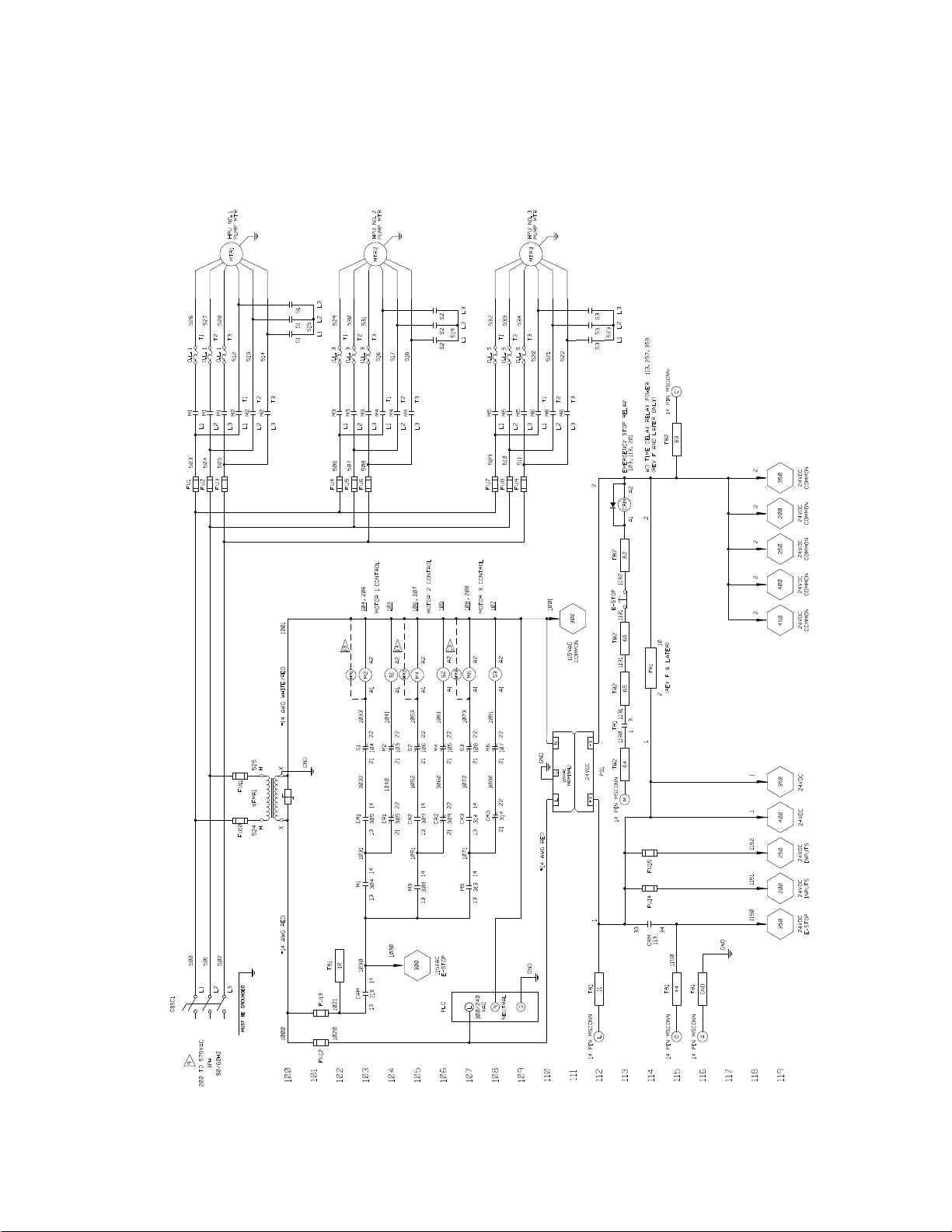
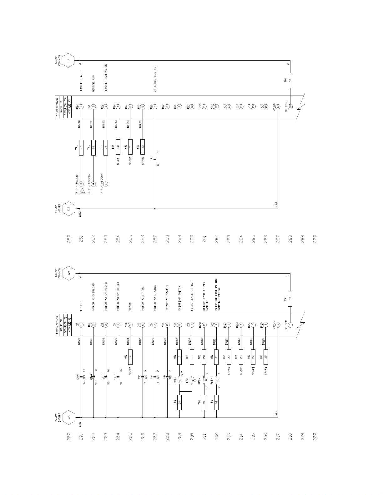
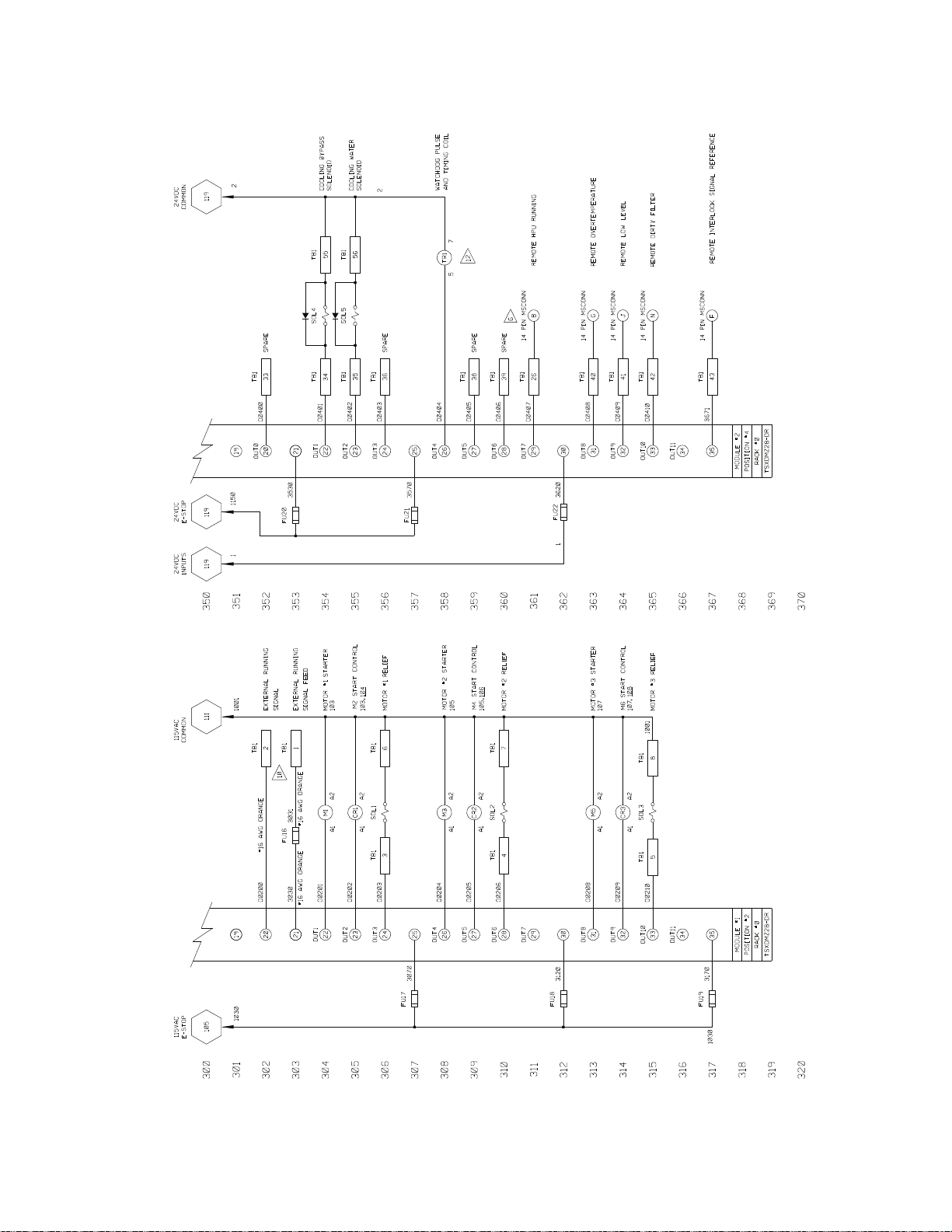
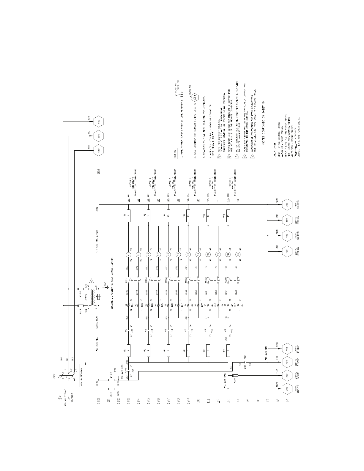
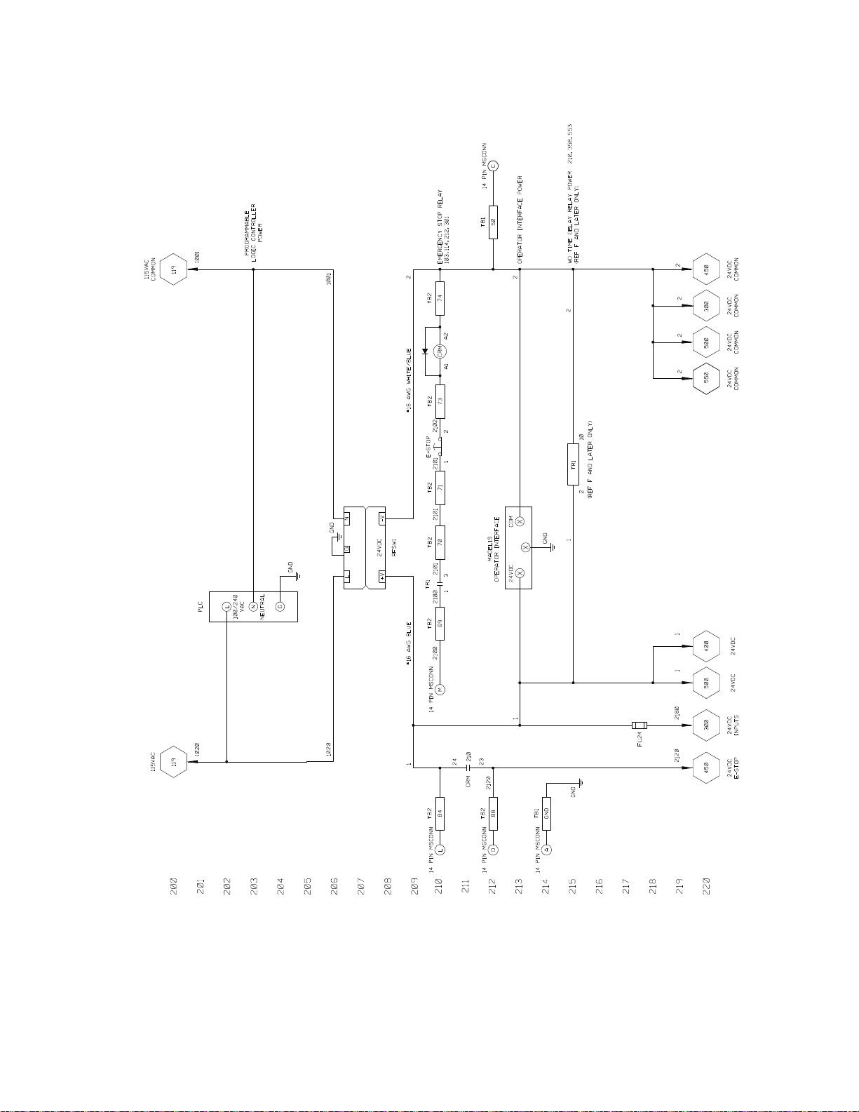
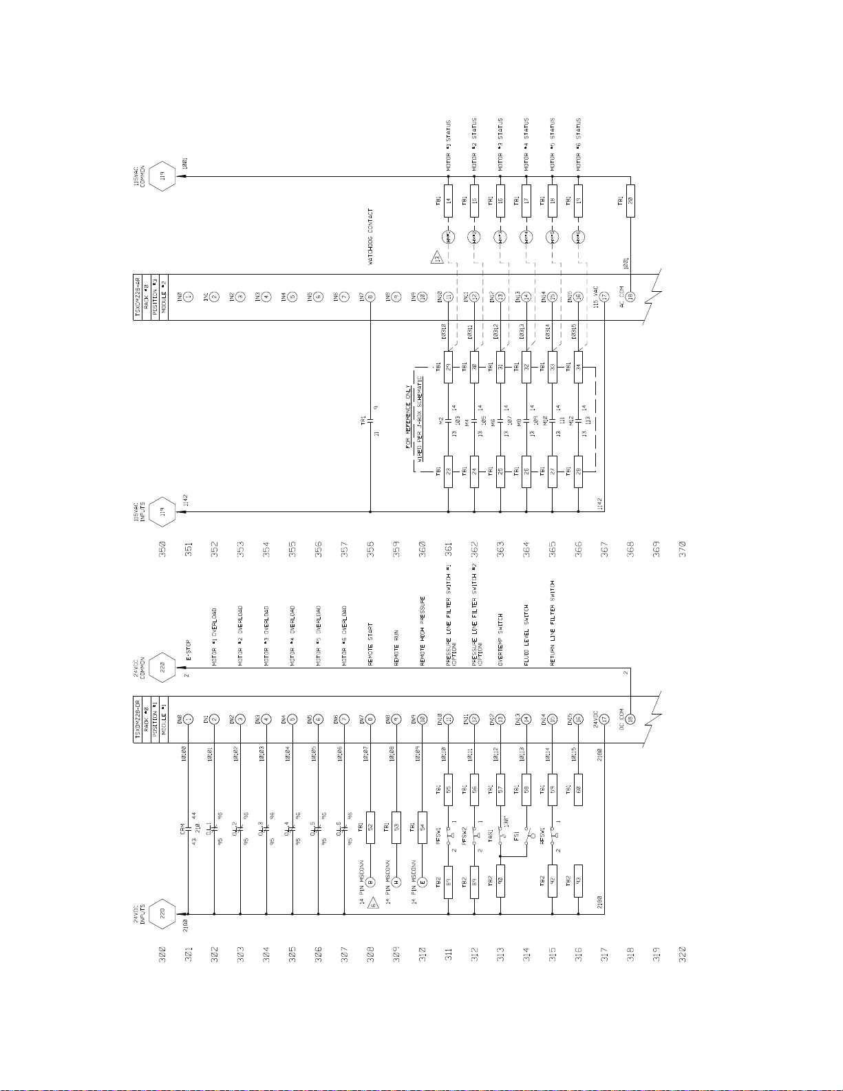
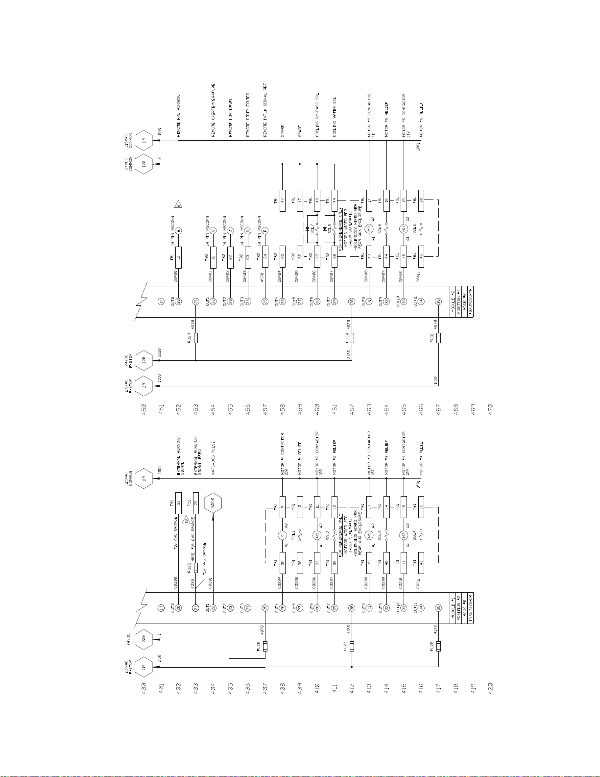
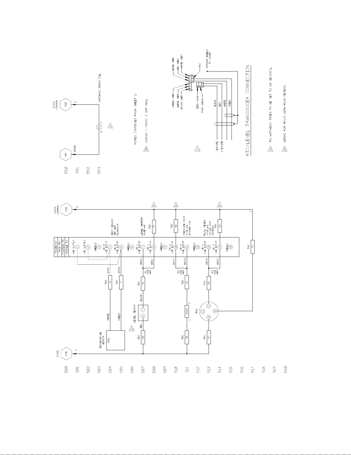
Model 505.60/.90 Electrical Schematic
The electrical schematic shows the electrical layout of the Model 505.60/.90
HPU.
Model 505.60/.90 Electrical Schematic
Model 505.60 - 505.180 SilentFlo™ HPU Introduction
23
Page 24
Model 505.60/.90 Electrical Schematic
24
Introduction
Model 505.60 - 505.180 SilentFlo™ HPU
Page 25
Model 505.60/.90 Electrical Schematic
Model 505.60 - 505.180 SilentFlo™ HPU Introduction
25
Page 26
Model 505.120/.150/.180 Electrical Schematic
Model 505.120/.150/.180 Electrical Schematic
The electrical schematic shows the electrical layout of the Model 505.120/.150/
.180 HPU.
26
Introduction
Model 505.60 - 505.180 SilentFlo™ HPU
Page 27
Model 505.120/.150/.180 Electrical Schematic
Model 505.60 - 505.180 SilentFlo™ HPU Introduction
27
Page 28
Model 505.120/.150/.180 Electrical Schematic
28
Introduction
Model 505.60 - 505.180 SilentFlo™ HPU
Page 29
Model 505.120/.150/.180 Electrical Schematic
Model 505.60 - 505.180 SilentFlo™ HPU Introduction
29
Page 30
Model 505.120/.150/.180 Electrical Schematic
30
Introduction
Model 505.60 - 505.180 SilentFlo™ HPU
Page 31

Model 505.120/.150/.180 Electrical Schematic
Model 505.60 - 505.180 SilentFlo™ HPU Introduction
31
Page 32

Specifications
Specifications
Model 505.60–505.180 HPU General Specifications
Parameter Specification
Environmental
Operating temperature
Humidity
Hydraulic fluid
Typical operating
temperature range
Filtration (microns)
Output Pressure
Non-adjustab le reli ef valve
setting
Heat exchanger
Water pressure
Maximum pressure
Water hose (.60/.90)
Water hose (.120/.150/.180)
Typical operating range
Max tempinterlock pre-set
For use in a controlled environment.
5–40°C (40–104°F)
0–85% noncondensing
Exxon Mobil DTE 25 or Shell Tellus 46 AW
43–49°C (110–120°F)
3 microns nominal
21 MPa (3000 psi)
22.4 MPa (3250 psi)
Water-cooled
0.2–0.3 MPa (35–45 psi differential)
0.8 MPa (120 psi)
38 mm (1.5 in) NPT
51 mm (2 in) NPT
43-49°C (110-120°F)
55°C (131°F)
32
Hydraulic connections
Pressure
Return
Drain
Electrical Power
Line voltage
Control voltage
Introduction
2 inch SAE
2 inch SAE
-16 JIC
380–575 V AC
24 V DC
Model 505.60 - 505.180 SilentFlo™ HPU
Page 33

Model 505.60 HPU Specifications
Parameter Specification
Model 505.60 HPU Specifications
Pump/Motor
Number of pump/motors
Maximum continuous
pressure
Maximum flow capacity
Motor rating
Current draw
Reservoir capacity 950 L (250 gal) maximum
Water flow rating
(input temperature)
10°C (50°F)
15.5°C (60°F)
21.1°C (70°F)
26.7°C (80°F)
32.2°C (90°F)
*
†
Wye-Delta starter configuration
2
21 MPa (3000 psi)
200 L/m (53.2 gpm) at 50 Hz
227 L/m (60 gpm) at 60 Hz
45 kW (60 hp) at 50/60 Hz
156 A continuous at 460 V AC 60 Hz
188 A continuous at 380 V AC 50 Hz
605 L (160 gal) minimum
34.1 L/m (9.0 gpm)
41.6 L/m (11 gpm)
56.8 L/m (15 gpm)
83.3 L/m (22 gpm)
177.9 L/m (47 gpm)
Heat load (maximum)
Dimensions
Length
Height
Width
Weight
Empty
With hydraulic fluid
‡
Noise
rating at 1 m
* For one motor
† For all motors
‡ Sound pressure level [dB(A)] is expressed as a free field value.
Readings may vary with the acoustic environment.
89.6 kW (306,000 Btu/hr)
2870 mm (1 13 in)
2006 mm (79 in)
990 mm (39 in)
1703 kg (3754 lb)
2276 kg (5017 lb) minimum fluid level
2615 kg (5766 lb) maximum fluid level
68 dB(A) fully compensated
Model 505.60 - 505.180 SilentFlo™ HPU Introduction
33
Page 34

Model 505.90 HPU Specifications
Model 505.90 HPU Specifications
Parameter Specification
Pump/Motor
Number of pump/motors
Maximum continuous
pressure
Maximum flow capacity
Motor rating
Current draw
Reservoir capacity 950 L (250 gal) maximum
Water flow rating
(input temperature)
10°C (50°F)
15.5°C (60°F)
21.1°C (70°F)
26.7°C (80°F)
32.2°C (90°F)
*
†
Wye-Delta starter configuration
3
21 MPa (3000 psi)
300 L/m (80 gpm) at 50 Hz
340 L/m (90 gpm) at 60 Hz
45 kW (60 hp) at 50/60 Hz
233 A continuous at 460 V AC 60 Hz
281 A continuous at 380 V AC 50 Hz
605 L (160 gal) minimum
56.0 L/m (14.8 gpm)
64.3 L/m (17 gpm)
83.3 L/m (22 gpm)
128.7 L/m (34 gpm)
268.7 L/m (71 gpm)
Heat load (maximum)
Dimensions
Length
Height
Width
Weight
Empty
With hydraulic fluid
‡
Noise
rating at 1 m
* For one motor
† For all motors
‡ Sound pressure level [dB(A)] is expressed as a free field value.
Readings may vary with the acoustic environment.
134.4 kW (459,000 Btu/hr)
2870 mm (1 13 in)
2006 mm (79 in)
990 mm (39 in)
2138 kg (4714 lb)
2711 kg (5977 lb) minimum fluid level
3051 kg (6726 lb) maximum fluid level
68 dB(A) fully compensated
34
Introduction
Model 505.60 - 505.180 SilentFlo™ HPU
Page 35

Model 505.120 HPU Specifications
Parameter Specification
Model 505.120 HPU Specifications
Pump/Motor
Number of pump/motors
Maximum continuous
pressure
Maximum flow capacity
Motor rating
Current draw
Reservoir capacity 1893 L (500 gal) maximum
Water flow rating
(input temperature)
10°C (50°F)
15.5°C (60°F)
21.1°C (70°F)
26.7°C (80°F)
32.2°C (90°F)
*
†
Wye-Delta starter configuration
4
21 MPa (3000 psi)
400 L/m (106.4 gpm) at 50 Hz
454 L/m (120 gpm) at 60 Hz
45 kW (60 hp) at 50/60 Hz
310 A continuous at 460 V AC 60 Hz
374 A continuous at 380 V AC 50 Hz
1211 L (320 gal) minimum
68.1 L/m (18.0 gpm)
71.9 L/m (19 gpm)
90.8 L/m (24 gpm)
113.6 L/m (30 gpm)
174.1 L/m (46 gpm)
Heat load (maximum)
Dimensions
Length
Height
Width
Weight
Empty
With hydraulic fluid
‡
Noise
rating at 1 m
* For one motor
† For all motors
‡ Sound pressure level [dB(A)] is expressed as a free field value.
Readings may vary with the acoustic environment.
179.2 kW (612,000 Btu/hr)
4270 mm (168 in)
2006 mm (79 in)
990 mm (39 in)
2896 kg (6384 lb)
3954 kg (8717 lb) minimum fluid level
4561 kg (10056 lb) maximum fluid level
70 dB(A) fully compensated
Model 505.60 - 505.180 SilentFlo™ HPU Introduction
35
Page 36

Model 505.150 HPU Specifications
Model 505.150 HPU Specifications
Parameter Specification
Pump/Motor
Number of pump/motors
Maximum continuous
pressure
Maximum flow capacity
Motor rating
Current draw
Reservoir capacity 1893 L (500 gal) maximum
Water flow rating
(input temperature)
10°C (50°F)
15.5°C (60°F)
21.1°C (70°F)
26.7°C (80°F)
32.2°C (90°F)
*
†
Wye-Delta starter configuration
5
21 MPa (3000 psi)
500 L/m (133 gpm) at 50 Hz
567 L/m (150 gpm) at 60 Hz
45 kW (60 hp) at 50/60 Hz
387 A continuous at 460 V AC 60 Hz
476 A continuous at 380 V AC 50 Hz
1211 L (320 gal) minimum
87.8 L/m (23.2 gpm)
94.6 L/m (25 gpm)
121.1 L/m (32 gpm)
159.0 L/m (42.0 gpm)
265.0 L/m (70 gpm)
Heat load (maximum)
Dimensions
Length
Height
Width
Weight
Empty
With hydraulic fluid
‡
Noise
rating at 1 m
* For one motor
† For all motors
‡ Sound pressure level [dB(A)] is expressed as a free field value.
Readings may vary with the acoustic environment.
224 kW (765,000 Btu/hr)
4270 mm (168 in)
2006 mm (79 in)
990 mm (39 in)
3313 kg (7305 lb)
4372 kg (9638 lb) minimum fluid level
4979 kg (10977 lb) maximum fluid level
71 dB(A) fully compensated
36
Introduction
Model 505.60 - 505.180 SilentFlo™ HPU
Page 37

Model 505.180 HPU Specifications
Parameter Specification
Model 505.180 HPU Specifications
Pump/Motor
Number of pump/motors
Maximum continuous
pressure
Maximum flow capacity
Motor rating
Current draw
Reservoir capacity 1893 L (500 gal) maximum
Water flow rating
(input temperature)
10°C (50°F)
15.5°C (60°F)
21.1°C (70°F)
26.7°C (80°F)
32.2°C (90°F)
*
†
Wye-Delta starter configuration
6
21 MPa (3000 psi)
600 L/m (160 gpm) at 50 Hz
681 L/m (180 gpm) at 60 Hz
45 kW (60 hp) at 50/60 Hz
464 A continuous at 460 V AC 60 Hz
560 A continuous at 380 V AC 50 Hz
1211 L (320 gal) minimum
112.0 L/m (29.6 gpm)
128.7 L/m (34 gpm)
166.5 L/m (44 gpm)
257.4 L/m (68 gpm)
537.5 L/m (142 gpm)
Heat load (maximum)
Dimensions
Length
Height
Width
Weight
Empty
With hydraulic fluid
‡
Noise
rating at 1 m
* For one motor
† For all motors
‡ Sound pressure level [dB(A)] is expressed as a free field value.
Readings may vary with the acoustic environment.
269 kW (918,000 Btu/hr)
4270 mm (168 in)
2006 mm (79 in)
990 mm (39 in)
3731 kg (8226 lb)
4789 kg (10559 lb) minimum fluid level
5397 kg (11898 lb) maximum fluid level
72 dB(A) fully compensated
Model 505.60 - 505.180 SilentFlo™ HPU Introduction
37
Page 38

Model 505.180 HPU Specifications
38
Introduction
Model 505.60 - 505.180 SilentFlo™ HPU
Page 39

General Safety Practices: Hydraulic Power Units and
Safety
General Safety Practices: Hydraulic Power Units and Hydraulic Service Manifolds
The hydraulic power unit (HPU) provides high pressure hydraulic fluid to system
components for system operation. The hydraulic service manifold (HSM)
controls distribution of that hydraulic fluid pressure. Th is section provi des
general information about safety issues that pertain to system hydraulic supply
and distribution components. These issues include statements to the intended use
and foreseeable misuse of the system and definition for the graphical hazard
labeling that is affixed to your product, and other (more general) safety
information that relates to the high-pressure and high-performance characteristics
of MTS servohydraulic and electromechanical systems.
When you prepare to operate a system that includes environmental components,
ensure the following:
• Do not use or allow personnel to operate the system who are not
experienced, trained, or educated in the inherent dangers associated with
high-performance servo hydraulics and who are not experienced, trained, or
educated with regard to the intended operation as it applies to this test
system.
• Do not disable safety components or features (including limit detectors,
light curtains, or proximity switches/detectors).
• Do not attempt to operate the system without appropriate personal safety
gear (for example, hearing, hand, and eye protection).
• Do not modify the system or replace system components using parts that are
not MTS component parts or effect repairs using parts or components that
are not manufactured to MTS specifications.
• Do not use the system in a test area where uncontrolled access to the test
system is allowed when the system is in operation.
• For servohydraulic systems, do not operate the system unless an interlock is
installed to monitor supply pressure into the HSM and initiate a system
interlock if a low or no pressure event occurs.
If you have system related responsibilities (that is, if you are an operator, service
engineer, or maintenance person), you should study safety information carefully
before you attempt to perform any test system procedure.
You should receive training on this system or a similar system to ensure a
thorough knowledge of your equipment and the safety issues that are associated
with its use. In addition, you should gain an understanding of system functions
by studying the other manuals supplied with your test system. Contact MTS for
information about the content and dates of training classes that are offered.
Model 505.60 - 505.180 SilentFlo™ HPU Safety
39
Page 40

General Safety Practices: Hydraulic Power Units and
It is very important that you study the following safety information to ensure that
your facility procedures and the system’s operating environment do not
contribute to or result in a hazardous situation. Remember, you cannot eliminate
all the hazards associated with this system, so you must learn and remain aware
of the hazards that apply to your system at all times. Use these safety guidelines
to help learn and identify hazards so that you can establish appropriate training
and operating procedures and acquire appropriate safety equipment (such as
gloves, goggles, and hearing protection).
Each test system operates within a unique environment which includes the
following known variables:
• Facility variables (facility variables include the structure, atmosphere, and
utilities)
• Unauthorized customer modifications to the equipment
• Operator experience and specialization
• Test specimens
Because of these variables (and the possibility of others), your system can
operate under unforeseen circumstances that can result in an operating
environment with unknown hazards.
Improper installation, operation, or maintenance of your system can result in
hazardous conditions that can cause death, personal injury, or damage to the
equipment or to the specimen. Common sense and a thorough knowledge of the
system’s operating capabilities can help to determine an appropriate and safe
approach to its operation.
Read all manuals Study the contents of this manual and the other manuals provided with your
system before attempting to perform any system function for the first time.
Procedures that seem relatively simple or intuitively obvious may require a
complete understanding of system operation to avoid unsafe or dangerous
situations.
Locate and read
hazard placards/labels
Specimen temperature
changes
Know facility safe
procedures
Find, read, and follow the hazard placard instructions located on the equipment.
These placards are placed strategically on the equipment to call attention to areas
such as known crush points, electrical voltage, and high pressure hazards.
During environmental testing, the specimen temperature can become hot enough
to cause burns. Wear personal protection equipment (gloves) when handling
specimens.
Most facilities have internal procedures and rules regarding safe practices within
the facility. Be aware of these safe practices and incorporate them into your daily
operation of the system.
Know controls Before you operate the system for the first time, make a trial run through the
operating procedures with the power off. Locate all hardware and software
controls and know what their functions are and what adjustments they require. If
any control function or operating adjustment is not clear, review the applicable
information until you understand it thoroughly.
40
Safety
Model 505.60 - 505.180 SilentFlo™ HPU
Page 41

General Safety Practices: Hydraulic Power Units and
Have first aid available Accidents can happen even when you are careful. Arrange your operator
schedules so that a properly trained person is always close by to render first aid.
In addition, ensure that local emergency contact information is posted clearly and
in sight of the system operator.
Know potential crush
and pinch points
Be aware of
component movement
with hydraulics off
Know electrical
hazards
Be aware of potential crush and pinch points on your system and keep personnel
and equipment clear of these areas.
Remember, when hydraulic power is interrupted on a servohydraulic system, it is
likely that stored accumulator pressure will persist for some time within the
system. In addition, it is likely that as stored energy dissipates, gravity will cause
portions of the system to move.
The actuator rod can also drift down when hydraulics are turned off hitting
anything in its path. This uncommanded movement is because of oil movement
between the pressure/return ports and oil blow by across the piston hub. Be aware
that this can happen and clear the area around the actuator rod when hydraulics
are turned off.
When the system electrical power is turned on, minimize the potential for
electrical shock hazards. Wear clothing and use tools that are properly insulated
for electrical work. Avoid contact with exposed wiring or switch contacts.
Whenever possible, turn off electrical power when you work on or in proximity
to any electrical system component. Observe the same precautions as those given
for any other high-voltage machinery.
Make sure that all electrical components are adequately grounded. Grounds must
remain connected and undisturbed at all times.
Keep bystanders
safely away
Keep bystanders at a safe distance from all equipment. Never allow bystanders to
touch specimens or equipment while the test is running.
Wear proper clothing Do not wear neckties, shop aprons, loose clothing or jewelry, or long hair that
could get caught in equipment and result in an injury. Remove loose clothing or
jewelry and restrain long hair.
Remove flammable
fluids
Check bolt ratings and
torques
Remove flammable fluids from their containers or from components before you
install the container or component. If desired, you can replace the flammable
fluid with a non-flammable fluid to maintain the proper proportion of weight and
balance.
To ensure a reliable product, fasteners (such as bolts and tie rods) used in MTSmanufactured systems are torqued to specific requirements. If a fastener is
loosened or the configuration of a component within the system is modified, refer
to information in this product manual to determine the correct fastener, fastener
rating, and torque. Overtorquing or undertorquing a fastener can create a
hazardous situation due to the high forces and pressures present in MTS test
systems.
On rare occasions, a fastener can fail even when it is correctly installed. Failure
usually occurs during torquing, but it can occur several days later. Failure of a
fastener can result in a high velocity projectile. Therefore, it is a good practice to
avoid stationing personnel in line with or below assemblies that contain large or
long fasteners.
Model 505.60 - 505.180 SilentFlo™ HPU Safety
41
Page 42

General Safety Practices: Hydraulic Power Units and
Practice good
housekeeping
Protect hoses and
cables
Provide proper
hydraulic fluid
filtration
Protect accumulators
from moving objects
Do not exceed the
Maximum Supply
Pressure
Keep the floors in the work area clean. Hydraulic fluid that is spilled on any type
of floor can result in a dangerous, slippery surface. Do not leave tools, fixtures,
or other items not specific to the test, lying about on the floor, system, or decking.
Protect electrical cables from spilled hydraulic fluid and from excessive
temperatures that can cause the cables to harden and eventually fail. Ensure that
all cables have appropriate strain relief devices installed at the cable and near the
connector plug. Do not use the connector plug as a strain relief.
Protect all system hoses and cables from sharp or abrasive objects that can cause
the hose or cable to fail. Never walk on hoses or cables or move heavy objects
over them. Consider hydraulic distribution system layout and route hoses and
cables away from areas that expose them to possible damage.
If the system is equipped with a non-MTS hydraulic power unit, ensure proper
filtration to the hydraulic distribution system and testing component s. Particles
present in hydraulic fluid and cause erratic or poor system response.
Protect accumulators with supports or guards. Do not strike accumulators with
moving objects. This could cause the accumulator(s) to separate from the
manifold resulting in equipment damage and personal injury.
For hydraulic grips and fixtures. make sure that the hydraulic supply pressure is
limited to the maximum pressure defined by the grip or fixture identification (ID)
tag.
Do not disable safety
devices
Use appropriately
sized fuses
Provide adequate
lighting
Provide means to
access out-of-reach
components
Wear appropriate
personal protection
Your system may have active or passive safety devices installed to prevent
system operation if the device indicates an unsafe condition. Do not disable such
devices as it may result in unexpected system motion.
Whenever you replace fuses for the system or supply, ensure that you use a fuse
that is appropriately sized and correctly installed. Undersized or oversized fuses
can result in cables that overheat and fuses that explode. Either instance creates a
fire hazard.
Ensure adequate lighting to minimize the chance of operation errors, equipment
damage, and personal injury. You need to see what you are doing.
Make sure you can access system components that might be out of reach while
standing on the floor. For example, ladders or scaffolding might be required to
reach load cell connectors on tall load units.
Wear eye protection when you work with high-pressure hydraulic fluid,
breakable specimens, or when anything characteristic to the specimen could
break apart.
W ear ear protection when you work near electric motors, pumps, or other devices
that generate high noise levels. Some systems can create sound pressure levels
that exceed 70 dbA during operation.
W ear appropriate personal protection equipment (gloves, boots, suits, respirators)
whenever you work with fluids, chemicals, or powders that can irritate or harm
the skin, respiratory system, or eyes.
42
Safety
Model 505.60 - 505.180 SilentFlo™ HPU
Page 43

General Safety Practices: Hydraulic Power Units and
Handle chemicals
safely
Know system
interlocks
Whenever you use or handle chemicals (for example, cleaning fluids, hydraulic
fluid, batteries, contaminated parts, electrical fluids, and maintenance waste),
refer to the appropriate MSDS documentation for that material and determine the
appropriate measures and equipment required to handle and use the chemical
safely. Ensure that the chemical is disposed of appropriately.
Interlock devices should always be used and properly adjusted. Interlock devices
are designed to minimize the chance of accidental damage to the test specimen or
the equipment. Test all interlock devices for proper operation immediately before
a test. Do not disable or bypass any interlock devices as doing so could allow
hydraulic pressure to be applied regardless of the true interlock condition. The
Reset/Override button is a software function that can be used to temporarily
override an interlock while attempting to gain control of the system.
Know system limits Never rely on system limits such as mechanical limits or software limits to
protect you or any personnel. System limits are designed to minimize the chance
of accidental damage to test specimens or to equipment. T est all limits for proper
operation immediately before a test. Always use these limits and adjust them
properly.
Do not disturb sensors Do not bump, wiggle, adjust, disconnect, or otherwise disturb a sensor (such as
an accelerometer or extensometer) or its connecting cable when hydraulic
pressure is applied.
Ensure secure cables Do not change any cable connections when electrical power or hydraulic pressure
is applied. If you attempt to change a cable connection while the system is in
operation, an open control loop condition can result. An open control loop
condition can cause a rapid, unexpected system response which can result in
severe personal injury, death, or damage to equipment. Also, ensure that all
cables are connected after you make any changes in the system configuration.
Stay alert A void long periods of work without adequate rest. In addition, avoid long periods
of repetitious, unvarying, or monotonous work because these conditions can
contribute to accidents and hazardous situations. If you are too familiar with the
work environment, it is easy to overlook potential hazards that exist in that
environment.
Contain small leaks Do not use your fingers or hands to stop small leaks in hydraulic or pneumatic
hoses. Substantial pressures can build up, especially if the hole is small. These
high pressures can cause the oil or gas to penetrate your skin, causing painful and
dangerously infected wounds. Turn off the hydraulic supply and allow the
hydraulic pressure to dissipate before you remove and replace the hose or any
pressurized component.
Stay clear of moving
equipment/avoid crush
points
Stay clear of mechanical linkages, connecting cables, and hoses that move
because you can get pinched, crushed, tangled, or dragged along with the
equipment. High forces generated by the system can pinch, cut, or crush anything
in the path of the equipment and cause serious injury. Stay clear of any potential
crush points. Most test systems can produce sudden, high-force motion. Never
assume that your reactions are fast enough to allow you to escape injury when a
system fails.
Model 505.60 - 505.180 SilentFlo™ HPU Safety
43
Page 44

General Safety Practices: Hydraulic Power Units and
Know the causes of
unexpected actuator
motions
Do not use RF
transmitters
Know compressed gas
hazards
The high force and velocity capabilities of MTS actuators can be destructive and
dangerous (especially if actuator motion is unexpected). The most likely causes
of unexpected actuator response are operator error and equipment failure due to
damage or abuse (such as broken, cut, or crushed cables and hoses; shorted wires;
overstressed feedback devices; and damaged components within the servocontrol
loop). Eliminate any condition that could cause unexpected actuator motion.
Keep radio frequency (RF) transmitters away from the workstation computers,
remote terminals, and electronics consoles. Intense RF fields can cause erratic
operation of the more sensitive circuits in the system.
Some environmental chambers use liquid nitrogen or some inert gas to achieve a
required test atmosphere. Typically these gasses are supplied in pressurized
tanks.
Observe the following safety practices when you work with high-pressure air or
gases:
• When you charge an accumulator, follow all the charging instructions
provided in the appropriate product information manuals. When precharging
accumulators, properly identify the type of gas to be used and the type of
accumulator to be precharged.
• Use only dry-pumped nitrogen to precharge nitrogen-charged accumulators.
(Dry-pumped nitrogen can also be labeled “oil pumped” or “dry water
pumped.”) Do not use compressed air or oxygen for precharging: the
temperature increase caused by rapid gas compression can result in highly
explosive conditions when hydraulic fluid is in the presence of oxygen or
compressed air.
• Always follow the recommended bleeding procedures before you remove or
disassemble components that contain pressurized gas. When you bleed a gas
or remove a fitting, hose, or component that contains a gas, remember that
many gases cannot support life. Therefore, as the ratio of released gas to
oxygen increases, so does the potential for suffocation.
• Wear appropriate safety devices to protect your hearing. Escaping air or gas
can create a noise level that can damage your hearing.
• Ensure that all pressurized air or gas is bled out of a pneumatic or gas-
charged device before you start to disassemble it. A thorough understanding
of the assembly and its pressurized areas is necessary before you undertake
any maintenance. Refer to the appropriate product information for the
correct bleeding procedure.
It may not be obvious or intuitive which bolts or fittings are used to restrain
a pressurized area. On some assemblies, you must remove a cover plate to
gain access to the structural bolts. Sometimes, to protect you from a rapid
release of trapped gases, a small port is exposed when you remove this
cover plate. Exposing this port ensures that the gas precharge is fully bled
before disassembly. However, this is not the recommended procedure for
bleeding a pneumatic or gas-charged device, because it can expose you to
the dangers of escaping compressed gas and particulates that are expelled
from the chamber or around the seals. Do not assume that cover plates and
ports are installed in all the critical locations.
44
Safety
Model 505.60 - 505.180 SilentFlo™ HPU
Page 45

Consult MTS when in doubt about the safety or reliability of any system-related
procedure or modification that involves devices that contain any type of
compressed gas.
Hazard Placard Placement
Hazard placards contain specific safety information and are affixed directly to the
system so they are plainly visible.
Each placard describes a system-related hazard. When possible, international
symbols (icons) are used to graphically indicate the type of hazard and the
placard label indicates its severity. In some instances, the placard may contain
text that describes the hazard, the potential result if the hazard is ignored, and
general instructions about how to avoid the hazard.
The following labels and placards are typically located on the HPU.
Label Description
Hazard Placard Placement
Hydraulic Power Unit information
label.
Part # 055-526-401
Overcurrent protection provided at
machine supply terminals.
Part # 100-008-434
Model 505.60 - 505.180 SilentFlo™ HPU Safety
45
Page 46

Hazard Placard Placement
Label Description
Caution
To prevent equipment damage and
impede performance, remove red
shipping plug under filler cap before
operating.
Replace with black plastic snap in
strainer.
Part # 050-174-101
Warning
Disconnect unit from the electrical
supply before opening enclosure.
Part # 100-008-037
Wye-Delta Connections
Use for single voltage 6 lead motors
suitable for wye-delta starting.
Part # 053-448-401
46
Safety
Model 505.60 - 505.180 SilentFlo™ HPU
Page 47

Model 505.60—505.180 HPU Electrical, Hydraulic, and
CAUTION
When moving the HPU with
a fork lift or pallet jack, lift the
HPU from both ends.
When moving the HPU with an
overhead lift, use a spreader bar
to help balance the weight.
Installation
Contents Model 505.60—505.180 HPU Electrical, Hydraulic, and Water
Connections 47
Model 505.60 HPU Setup 52
Testing Model 505.60 HPU Operation 56
Precharging the Optional Surge Suppressor Accumulator 59
Model 505.60—505.180 HPU Electrical, Hydraulic, and Water Connections
1. Position the hydraulic power unit.
Lifting the HPU in the middle of its chassis can strain the structural integrity
of the HPU.
Do not lift the HPU in the middle of its chassis.
Lift the HPU from each end of the chassis, as shown in the next figure.
Model 505.60 - 505.180 SilentFlo™ HPU Installation
47
Page 48

Model 505.60—505.180 HPU Electrical, Hydraulic,
CAUTION
2. Determine where to put the HPU. Consider the following:
• The room dimensions must be adequate to accommodate the HPU.
– Refer to your local electrical codes for the required free space
surrounding the HPU.
– A minimum of 914.4 mm (36 in) between the ends of the HPU and any
obstruction.
– The rear of the HPU can be as close as 25.4 mm (1 in) to the wall.
– A minimum of 2362.2 mm (93 in) from the floor to an overhead
obstruction.
• The HPU can fit through a standard 1.04-m or 41-in door.
• The HPU can be moved by a fork lift, pallet jack, or over head crane. Read
the caution on the previous page.
• Placement considerations should include proximity to the facility electric
power and the hydraulic components. Positioning the HPU close to the
hydraulic components can reduce the cost of hydraulic distribution.
• The HPU produces no more than 72 dB (A) of sound pressure level fully
compensated in a free field acoustic environment.
3. Connect the electrical service to the HPU.
Note Local electrical codes supersede any information found here.
Electrical connections must be made by qualified personnel and conform to
local codes and regulations. The electrical box has a power disconnect
switch that must be off (O) in order to open the electrical box. An electrical
service panel to provide the electrical power feed (line voltage) to the HPU
is not necessary, but may be required by local electrical codes.
A. Connect the three or six (if parallel phase conductors are used)
electrical power feed wires to the input lugs of the power disconnect in
a counterclockwise phase orientation as indicated by the L3, L2, and
L1 labels shown in the next figure (Model 505.90 shown, the location
of the disconnect and ground varies slightly on other models).
Incorrect motor rotation at high pressure can cause severe damage to your
HPU.
It is imperative that you verify proper motor rotation while in low pressure, as
described in Step 6, to assure proper operation of the HPU and to prevent
damage to the HPU.
48
Installation
Model 505.60 - 505.180 SilentFlo™ HPU
Page 49

Model 505.60—505.180 HPU Electrical, Hydraulic, and
PE GND (Protective
Earth Ground) Lug
Power
Disconnect
Electrical Power Feed
Lugs (shown labeled for
counterclockwise phase
orientation)
Ensure that lugs are
secure. They should be
checked periodically;
Refer to the
Maintenance section.
HPU Power Requirement
and Power Feed Phase
Orientation Identifier
B. Connect the grounding wire to the lug labeled PE GND (protective
earth ground).
4. Connect the hydraulic and water lines.
Model 505.60 - 505.180 SilentFlo™ HPU Installation
49
Page 50

Model 505.60—505.180 HPU Electrical, Hydraulic,
505.60/.90 505.120/.180
2 inch Female
NPT Water In
2 inch Female
NPT Water In
2 inch SAE Code
61 Pressure
2 inch SAE
Code 61 Return
-16 JIC Drain
1-1/2 inch Female
NPT Water In
2 inch SAE Code
61 Return
1-1/2 inch Female
NPT Water Out
2 inch SAE
Code 61
Pressure
-16 JIC
Drain
Note For hydraulic connections to air-cooled units, refer to the Air-Cooler to
SilentFlo HPU Integration Product Information manual (MTS part number
100-135-073).
Each port is labeled on the manifold. Take care to identify and correctly
make these connections. Failure to make proper connection could lead
to water in the hydraulic fluid, hydraulic fluid in the cooling water, or
pressurization of low pressure lines.
The HPU requires connection to a suitable water supply to cool the
hydraulic fluid. The differential pressure required between the HPU
water inlet and outlet connections is 0.2–0.3 MPa (30–45 psi). The
maximum allowable water inlet pressure is 0.8 MPa (120 psi).
50
Installation
A. Connect the hydraulic pressure and drain lines to the hydraulic fluid
distribution system or directly to a hydraulic device. Use hydraulic line
or hose that is rated to handle the maximum hydraulic pressure of the
HPU.
Note If check valves are installed on the pressure or return ports, an extension
tube might be required on the drain port to aid in final connection to the
system drain line.
B. An appropriate shutoff valve should be installed between the water
source and HPU.
C. Connect the water supply to the HPU Water In port. Connect the
Water Out port to your drain line.
Model 505.60 - 505.180 SilentFlo™ HPU
Page 51

Model 505.60—505.180 HPU Electrical, Hydraulic, and
D. A regulating valve must be adjusted according to your water
temperature. For a description of how to set the water regulating valv e
see, the “Changing the Water Flow” procedure.
The water supply must also be capable of maintaining water flow at a rate
listed in the following table.
Water
Model Number
Temperature
505.60 505.90 505.120 505.150 505.180
10.0°C (50°F) 34.1 L/m
(9.0 gpm)
15.5°C (60°F) 41.6 L/m
(1 1 gp m)
21.1°C (70°F) 56.8 L/m
(15 gpm
26.7°C (80°F) 83.3 L/m
(22 gpm)
32.2°C (90°F) 177.9 L/m
(47 gpm)
56.0 L/m
(14.8 gpm)
64.3 L/m
(17 gpm)
83.3 L/m
(22 gpm)
128.7 L/m
(34 gpm)
268.7 L/m
(71 gpm)
68.1 L/m
(18.0 gpm)
71.9 L/m
(19 gpm)
90.8 L/m
(24 gpm)
113.6 L/m
(30 gpm)
174.1 L/m
(46 gpm)
87.8 L/m
(23.2 gpm)
94.6 L/m
(25 gpm)
121.1 L/m
(32 gpm)
159.0 L/m
(42 gpm)
265.0 L/m
(70 gpm)
112.0 L/m
(29.6 gpm)
128.7 L/m
(34 gpm)
166.5 L/m
(44 gpm)
257.4 L/m
(68 gpm)
537.5 L/m
(142 gpm)
5. Add hydraulic fluid to the reservoir.
The unit is shipped with a plug in the filler cap. Remove the red filler cap
plug and install the screen in the fill port on the top of the reservoir. The
screen is shipped in the electrical enclosure.
Pump hydraulic fluid (filtered to 10 microns) into the reservoir. Stop when
the fluid level reaches the maximum fluid level as indicated by the oil level
dial gage
.
6. If provided, check the precharge pressure of the optional surge suppressor.
Refer to the appropriate procedure for complete instructions.
Model 505.60 - 505.180 SilentFlo™ HPU Installation
51
Page 52

Model 505.60 HPU Setup
Remote Control
Connector
7. Connect the controller cable (if used).
The controller cable provides a means to connect a remote controller to the
HPU. When connected, your controller can remotely start and stop the unit
and switch between the low and high pressure selections. The cable also
permits the controller to monitor the low level, over temperature, and dirty
filter status. For information about the connection, see the appropriate
electrical schematics.
Model 505.60 HPU Setup
Note If a controller is not used, the installed jumper plug must be used or the
unit will not start.
The following procedure should only be performed at HPU installation to verify
settings, when you replace the user interface panel, or if you need to change a
selection.
1. Rotate the power disconnect switch to the on (|) position.
When you apply power to the HPU the startup screen displays on the user
interface panel.
2. Verify that the platform displayed corresponds with the HPU model you are
installing.
• 505.60/.90 Selected—for a Model 505.60 or 505.90 HPU.
• 505.120/.150/.180 Selected—for a Model 505.120 or 505.150 or
505.180 HPU.
If the displayed platform is not correct, press and hold the platform selection
button until the selection changes (5 seconds).
52
Installation
Model 505.60 - 505.180 SilentFlo™ HPU
Page 53

Model 505.60 HPU Setup
Platform Selection
Button
Main Display
Selection Button
Remote not selected
Note This selection can also be made from the HPU Setup panel.
Startup Screen (505.120/150/180 Platform selection shown)
3. On the user interface Main Display ensure that the Remote button under the
Master Unit Control is not selected (gray), indicating the HPU is in local
mode.
4. Press the Reset button to clear the interlock conditions that are the result of
initially applying power to the HPU.
Model 505.60 - 505.180 SilentFlo™ HPU Installation
53
Page 54

Model 505.60 HPU Setup
5. On the user interface panel, press and hold the HPU Setup button for five
seconds to display the HPU Setup panel.
6. Verify that the correct pumps are present for the HPU model installed.
• For Model 505.60, typically two pumps are present (three buttons are
displayed).
• For Model 505.90, typically three pumps are present (three buttons are
displayed).
• For Model 505.120, typically four pumps are present (six buttons are
displayed).
• For Model 505.150, typically five pumps are present (six buttons are
displayed).
• For Model 505.180, typically six pumps are present (six buttons are
displayed).
Note You can use these buttons to intentionally take a pump offline. For
example: in the figure above, pumps #1 through #5 are present (online),
pump #6 is not present (offline). This prevents pump #6 from being
enabled on the Main Panel. Clicking on the Pump #6 Not Present
button will place it online (the button turns green). Clicking on any of the
green Pump Present buttons will take that pump offline.
7. Check and, if desired, change the following selections:
A. Select your preference for temperature units.
Press the Temp Display button to display the desired units: Temp
Display in °C or Temp Display in °F.
B. Select your preference for the hydraulic pressure units:
54
Installation
Press the Pressure Display button to display the desired units:
Pressure Display in MPa or Pressure Display in psi.
Model 505.60 - 505.180 SilentFlo™ HPU
Page 55

Model 505.60 HPU Setup
C. If you are controlling the HPU with an external device connected to the
14-pin MS connector, select the polarity of the remote interlock signals
from the HPU to the controller.
Press the Remote Logic button to select: Remote Logic Normal
(active high) or Remote Logic Reverse (active low).
D. If a watchdog timer is present, press the Watchdog button to display
Watchdog Present.
If a watchdog timer is not present, press the Watchdog button to
display Watchdog Not Present.
E. Determine if the opti onal pressu re filter is installed.
If the pressure filter is present, press the Pressure Filter button to
display Pressure Filter Present.
If the pressure filter is not present, press the Pressure Filter button to
display Pressure Filter Not Present.
Note Skip Step F if you do not have a device that requires the auxiliary
contacts.
Model 505.60 - 505.180 SilentFlo™ HPU Installation
55
Page 56

Testing Model 505.60 HPU Operation
F. An auxiliary contact is available for the Model 505.120, 505.150, or
505.180 HPUs. This contact can be used to control an external device
such as a warning lamp or a remote cooling circuit.
This contact has two adjustment parameters. One controls the polarity
of the active states of the contact: Normal (active high) and Reverse
(active low). The other parameter controls whether the contact is active
whenever a pump motor is running (Aux Contact: On/Off) or
whenever a pump motor is running and
the temperature of the
hydraulic fluid in the reservoir reached the trip temperature (Aux
Contact: On/Off/Temp).
– Press the Aux Polarity: button to display Aux Polarity: Normal to
cause the contact to close when it is active.
– Press the Aux Polarity: button to display Aux Polarity: Reverse to
cause the contact to open when it is active.
– Press the Aux Contact: button to display Aux Contact: On/Off to to
activate the contact when at least one pump motor is running, and to
deactivate when no pump motors are running.
– Press the Aux Contact: button to display Aux Contact: On/Off/Temp
to activate the contact when at least one pump motor is running and
the
fluid temperature in the reservoir is above the temperature trip level
and to deactivate the contact when either the temperature is lower than
the temperature trip level or no pump motors are running.
– Press the Press to Set Aux T emp button to display the trip temperature
setup controls.
Press the up arrow to increase the trip temperature level.
Press the down arrow to decrease the trip temperature level.
Press Enter when the desired trip temperature level is displayed in the
HPU Setup panel.
Press Esc to disregard any changes and close the popup window.
8. Set up the optional ROD parameters.
If you have the run-on-demand option, refer to the appropriate procedure.
Testing Model 505.60 HPU Operation
Note If power is already on and the Main Display is showing on the User
Interface panel, start with Step 4.
1. Rotate the power disconnect switch to the on (|) position.
56
Installation
When you apply power to the HPU, the startup screen appears on the user
interface panel.
Model 505.60 - 505.180 SilentFlo™ HPU
Page 57

Testing Model 505.60 HPU Operation
Platform Selection
Button
Main Display
Selection Button
Hydraulic Fluid
Pressure Display
Enable/Disable Pumps Buttons
(the number of buttons displayed is determined
by the HPU Model)
2. Verify that the platform displayed corresponds with the HPU model you are
installing.
• 505.60/.90 Selected—for a Model 505.60 or 505.90 HPU.
• 505.120/.150/.180 Selected—for a Model 505.120 or 505.150 or
505.180 HPU.
If the displayed platform is not correct, press and hold the platform selection
button until the selection changes (5 seconds).
Note This selection can also be made from the HPU Setup panel.
Startup Screen (505.120/150/180 Platform selection shown)
3. Press the Main Display button to go to the Main Display panel.
Model 505.60 - 505.180 SilentFlo™ HPU Installation
57
Page 58

Testing Model 505.60 HPU Operation
4. Press the Reset button to clear any active interlock conditions.
5. Press the Pump #1 Enabled button to enable the first pump.
Note The following step only applies when the HPU is first turned on after the
6. Verify the motor rot ation (the pump motor can start with the wrong
For interlocks that do not clear, determine and correct the cause and then
press Reset.
electrical power has been connected.
rotation). Momentarily start the motor by pressing the Run/Low Pressure
button. The enabled pump will sequence on and start running in low
pressure.
• If the motor is rotating properly, the Hyd Fluid Pressure display
should read approximately 0.34 MPa (50 psi). Proceed to the next step.
• If the Hyd Fluid Pressure display shows no pressure, press the Stop
button to shut down the unit (do not run more than 10 seconds in the
wrong direction). Have a qualified electrician make a change in the
electrical phase to the HPU electrical power feed wires at the lugs
labeled L1, L2, and L3.
• If the connections were changed, repeat this step (Step 6) to confirm
that the pump is now outputting approximately 0.34 MPa (50 psi). If it
is not, contact MTS.
7. Verify the rotation of the remaining pum p motors.
A. Disable the currently enabled pump and enable the next successive
pump.
B. Momentarily start the motor by pressing the Run/Low Pressure
button. The enabled pump will sequence on and start running in low
pressure.
C. If the motor is rotating properly, the pressure on the operator interface
should read approximately 0.34 MPa (50 psi), repeat this step for each
remaining pump.
D. If the operator interface shows no pressure, press the Stop button to
shut down the unit (do not run more than 10 seconds in the wrong
direction). Make a note identifying the pump. Repeat this step for each
remaining pump.
E. Have a qualified electrician compare the power feeds coming into the
individual starter boxes of the pumps that are rotating correctly with
the pumps that are rotating incorrectly. The wiring sequence should be
the same for all boxes; for example black, white, red. If necessary,
correct the connection sequence and verify pump operation. Otherwise
contact MTS.
58
Installation
F. Check each pump for unusual noises or leaks. If a problem is found,
press the Stop button . You must correct the problem before you
continue.
8. Verify the correct output pressure.
Model 505.60 - 505.180 SilentFlo™ HPU
Page 59

Precharging the Optional Surge Suppressor
A. Enable the first pump.
B. Press the Run/Low Pressure button. The enabled pump will sequence
on and start running in low pressure.
C. Press the High Pressure button. The enabled pump will sequence to
high pressure.
D. Check for unusual noises or leaks. If a problem is found, press the Stop
button. You must correct the problem before you continue.
E. Verify that the Hyd Fluid Pressure display indicates high pressure
[typically 21 MPa (3000 psi)].
F. If necessary, refer to the appropriate procedure, and adjust the
hydraulic pressure for the enabled pump.
G. Press the High Pressure button to return to the low pressure mode.
H. Enable the next pump and disable the pump yo u just checked.
I. Repeat Step 8C through 8H for each remaining pump.
J. Enable one pump only and select low pressure.
K. Run the pump in low pressure for about three hours to filter the new
hydraulic fluid.
9. After filtering is complete, press the Stop button.
Precharging the Optional Surge Suppressor Accumulator
The surge suppressor, if provided, smooths out the ripple caused by the pulsing
action of the pump as it pressurizes the hydraulic fluid. The surge suppressor is a
cylinder that has an outer sleeve that is pressurized with nitrogen. The gas
pressurized sleeve dampens the pressure pulses.
The surge suppressor is mounted to the output of the hydraulic pump inside the
reservoir.
It is normal for a small amount of surge suppressor precharge loss to occur during
operation. Because of this gradual reduction in precharge pressure, the pressure
should be checked and recharged (if necessary) at regular intervals.
Determining a
pressure check
interval
The precharge pressure checking intervals of your surge suppressor depends on
how your system is used. Vigorous use causes more rapid pressure loss and thus
requires checking and recharging more often.
Initially, check the surge suppressor precharge pressure every month or 160
operating hours. If the precharge pressure changes more than 1.4 MPa (200 psi)
during this time period, recharge the surge suppressor and check the pressure
twice as often in the future. If the precharge pressure changes less than 1.4 MPa
(200 psi), check the pressure half as often.
Model 505.60 - 505.180 SilentFlo™ HPU Installation
59
Page 60

Precharging the Optional Surge Suppressor
High Pressure Gage
0–21 MPa (0–3000 psi)
Gage Protector (factory
set to limit pressure to
the gage to
approximately 1.4 MPa
(200 psi)
Extension Hose
Bleed Valve
Input Check
Valve
Nitrogen Supply Hose
Regulator Output
Pressure Gage
Nitrogen Bottle
Pressure Gage
Core-Type Valve
To Open and Close Use
Chuck Valve
Nitrogen
Bottle
Nitrogen
Bottle Valve
Regulator Output
Pressure Valve
Regulator ShutOff Valve
You must supply these items:
Check Valve
Locknut
Valve Stem
Open
Close
Poppet-Type Valve
To Open and Close Use
Chuck Valve
Close
Valve Stem
Valve Core
Open
Open
Close
Low Pressure Gage
0–2.1 MPa (0–300 psi)
When you have established a regular interval for checking the precharge
pressure, note the amount of pressure loss that occurs each time the pressure is
checked. An increase in pressure loss during the period between checks might
indicate that the surge suppressor seals or bladder require replacement.
Checking the
precharge pressure
The nitrogen precharge should be about 50–60% of the output pressure. To check
the accumulator precharge:
1. Turn the HPU off and ensure that the hydraulic pressure is zero before
proceeding.
2. Connect the charging kit chuck valve to the valve stem on the accumulator,
or to the remote charge valve on the reservoir top, if supplied.
3. With an open-end wrench, turn the locknut counterclockwise on the
accumulator valve assembly to open the valve. Read the pressure on the
high pressure gage.
• If the pressure reading is outside the range of 10.3–12.5 MPa (1500–
1800 psi), perform the procedure “Changing the Precharge Pressure.”
• If the pressure level is within the range of 10.3–12.5 MPa (1500–1800
psi), turn the locknut clockwise to close the valve and continue this
procedure.
4. Open the bleed valve on the accumulator charging kit and remove the chuck
valve from the accumulator. Replace the valve stem cap and protective
cover on the accumulator.
60
Installation
Charging Kit
Model 505.60 - 505.180 SilentFlo™ HPU
Page 61

Precharging the Optional Surge Suppressor
WARNING
CAUTION
Changing the
precharge pressure
The nitrogen precharge should be within the range of 10.3–12.5 MPa (1500–
1800 psi) which is 50–60% of the output pressure (21 MPa or 3000 psi). Perform
one of the following procedures to change the precharge pressure.
Decreasing pressure To decrease the precharge pressure:
1. Slowly open the bleed valve on the charging kit until gas begins to escape.
When the pressure reading on the appropriate pressure gage drops to the
level required, close the bleed valve.
2. Close the locknut. Open the bleed valve on the accumulator charging kit and
remove the chuck valve from the accumulator.
3. Install the valve stem cap and protective cover.
Increasing pressure To increase the precharge pressure:
1. Close the locknut on the accumulator.
2. Open the bleed valve two turns.
Precharging with a gas other than dry nitrogen will cause the existing
nitrogen within the surge suppressor to be mixed with the new gas.
Mixing gases can produce unpredictable results.
Use only dry nitrogen gas to precharge the surge suppressors.
3. Connect the nitrogen supply hose from the supply bottle pressure regulator
output to the input check valve on the charging kit.
4. Open the nitrogen bottle valve. Check the nitrogen bottle pressure gage on
the regulator. (The bottle must contain sufficient pressure to provide an
adequate gas volume.)
5. Monitor the regulator output pressure gage and adjust the regulator output
pressure valve to the required level.
Avoid rapid and extreme pressure transitions.
Rapid flow rates with pressure differentials of more than 2.1 MPa (300 psi)
across the input check valve can damage the valve seal(s).
Do not allow rapid flow rates. Open the regulator shut-off valve only far enough to
permit a gradual transfer of gas.
Model 505.60 - 505.180 SilentFlo™ HPU Installation
61
Page 62

Precharging the Optional Surge Suppressor
6. Slowly open the regulator shut-off valve until gas is heard escaping from the
accumulator charging kit bleed valve. Allow gas to slowly escape for
approximately ten seconds, and then close the bleed valve. Immediately
close the regulator shut-off valve before the pressure reading on either the
high or low charging kit pressure gage exceeds the pressure level of the
accumulator.
7. Open the locknut. Slowly open the regulator shut-off valve until the pressure
indicator on either the high or low charging kit pressure gage begins to rise.
When the pressure is at the required pressure level, close the regulator shutoff valve.
8. Close the locknut.
9. Open the bleed valve on the charging kit and remove the chuck valve from
the accumulator.
10. Install the valve stem cap and protective cover. Close the valve on the
nitrogen bottle.
62
Installation
Model 505.60 - 505.180 SilentFlo™ HPU
Page 63

Operation
Contents Model 505.60 HPU Startup Panel 64
Model 505.60 HPU Main Display 66
Model 505.60 HPU Data 68
Model 505.60 HPU Status 69
Model 505.60 HPU Setup 70
ROD Setup 72
Operating the Model 505.60 HPU Locally or Remotely 74
Recovering From an Interlock 76
Changing the Water Flow 78
Resetting the Thermal Overloads 79
Adjusting the Model 505.60 Hydraulic Pressure 81
Low/High Pressure Functionality 83
Setting Up Run-On-Demand 85
Model 505.60 - 505.180 SilentFlo™ HPU Operation
63
Page 64

Model 505.60 HPU Startup Panel
Model 505.60 HPU Startup Panel
The Series 505.60/.90 and 505.120–.180 HPUs have similar user interface
panels. The primary difference is the number of pumps that are displayed. This is
determined by the HPU Model. The controls for the various panels are shown
and described on the following page.
505.60/90 Platform
505.120/150/180 Platform
64
Operation
Model 505.60 - 505.180 SilentFlo™ HPU
Page 65

Model 505.60 HPU Startup Panel
The Startup Screen displays whenever power is first applied to the HPU through
the power disconnect switch on the starter box.
Startup Screen Controls Descriptions
Control Description
Language buttons Select user interface language. Language can be re-selected at HPU power up.
505.60/.90 Selected,
505.120/.150/.180 Selected
toggle button
Main Display button
Selects the HPU platform. The selected platform corresponds to the Model of
the HPU installed.
This button uses a 5 second delay to prevent inadvertent switching of the HPU
platform. Pressing and holding the button for five seconds switches from the
platform that is displayed to the other HPU platform.
Click on this button the open the Main Display panel.
Model 505.60 - 505.180 SilentFlo™ HPU Operation
65
Page 66

Model 505.60 HPU Main Display
Pump Disabled
Buttons
Pump Enabled
Buttons
Display Selector
Buttons
Master Unit
Controls
Model 505.60 HPU Main Display
Main Panel Display Controls
Control Descriptions
Master Unit Controls
Stop button
Turns off hydraulic pressure to the system. The button turns red when the HPU
is stopped.
Run/Low Pressure
button
High Pressure
button
Turns each enabled pump on in low pressure mode. The button turns green
when it is on.
Toggles each running pump between low and high pressure. The button turns
green when high pressure is selected and turns gray when low pressure is
selected.
Remote button
Enables the interface with your system controller. When selected (green) your
system controller can turn the HPU on and off, select low and high pressu re,
and monitor HPU status such as oil temperature, fluid level, and filter status.
When in Remote, the Run/Low Pressure and High Pressure buttons on the
user interface panel are disabled.
Auto Demand
(ROD) (optional)
button
When selected (green) automatically controls pump operation as system
demand changes.
Operation
66
Model 505.60 - 505.180 SilentFlo™ HPU
Page 67

Main Panel Display Controls (Continued)
Control Descriptions
Model 505.60 HPU Main Display
Pump Enable/Disable
Pump #1 through 6
Disabled buttons
Pump #1 through 6
Enabled buttons
Hyd Fluid Pressure display
Hyd Fluid Temp display
HPU Run Status
Run Status display
Fault Status
display
The number of buttons displayed is determined by the model of the HPU and
the selection made on the HPU Setup screen.
Disables the associated pump. The button is green if the pump is disabled.
Enables the associated pump. The button is green if the pump is enabled.
Displays the output pressure (in MPa or psi) of the HPU.
Displays the temperature (in °F or °C) of the hydraulic fluid in the reservoir.
Displays the current run status of the HPU. The status conditions may be:
• Off
• Run-Low
• Run- High
• Auto-Mode
Displays the current fault status of the HPU. If one or more faults exist, the
button will blink red and the message will alternate between Faulted and the
existing fault conditon(s). The display condition may be:
Panel selector buttons
Reset
• Normal (steady green)
• Faulted
• Overtemp
• Hyd Fluid Level
• Motor Overload
• Dirty
• Filter
• E-stop
Click on a gray button to display the screen for the selection. The selected
button turns white. The screens are described on the following pages.
The button is blue when all systems are normal.
The button is light blue when an interlock condition exists.
Clears any interlocks caused by the HPU (provided the reason fro the interlock
has been corrected). This switch operates independently from any other reset
functions in your control system.
Model 505.60 - 505.180 SilentFlo™ HPU Operation
67
Page 68

Model 505.60 HPU Data
Model 505.60 HPU Data
Control Descriptions
HPU Data
Pump Hours display
Hyd Fluid Pressure display
Hyd Fluid Temp display
Hyd Fluid Level display
Hyd Fluid Flow display
ROD Enabled display
Displays the running hours for each pump. The green bar indicates those
pumps that are currently enabled but not running (blinking green) and those
pumps currently enabled and running (solid green). The running hour display
for each pump can be changed if desired.
Displays the highest pressure of the running pumps.
Display the temperature of the hydraulic fluid in the reservoir.
Displays the level of the hydraulic fluid in the reservoir in 1/8 increments.
The level is relative to the bottom of the sensor, not the bottom of the reservoir
Displays if a flow meter is installed in the system.
Displays the total hydraulic fluid flow from all running pumps.
Displays only if the run-on-demand option is installed and if the option is
enabled from the Auto Demand (ROD) button on the Main Display screen.
68
Operation
Model 505.60 - 505.180 SilentFlo™ HPU
Page 69

Model 505.60 HPU Status
Control Descriptions
Model 505.60 HPU Status
HPU Status Screen
HPU Fault Status
Normal display
Hyd Fluid Temp
display
Hyd Fluid Level
display
Watchdog display
All these indicators should be green if they are within normal operating
parameters.
Indicator the HPU is operating properly.
Displays Hyd Fluid Temp Normal (green) when the temperature of the
hydraulic fluid in the reservoir is within normal limits.
If the temperature of the hydraulic fluid exceeds 55°C (131°F) the indicator
will turn red and indicate an over-temperature fault. An over-temperature
condition causes an interlock and turns off the HPU.
For more information, see the “Changing the Water Flow” procedure. After
reducing the temperature of the hydraulic fluid, press the Reset button to clear
the interlock. The indicator returns to Hyd Fluid Temp Normal (green).
The Hyd Fluid Level indicator turns red when the hydraulic fluid is below a
preset level.
Low fluid level will cause an interlock and turn the HPU off. The interlock
signal can be monitored by your system controller. After adding hydraulic fluid
to the reservoir, pr ess th e Reset button to clear the interlock.
This indicator is green when the PLC that controls the HPU is operating
normally.
This indicator turns red (indicating a watchdog fault) if the PLC stops
operating correctly. A watchdog fault cause the HPU to shutdown.
Return Filter
display
Indicates yellow when the filter needs replacement. A dirty filter condition will
prevent the HPU from being started, but it will not stop the HPU while it is
running. The signal can be monitored from the system controller.
Refer to the appropriate filter replacement procedure if necessary.
After replacing the filter, press the Reset button to clear the indication. The
indicator returns to Return Filter Normal (green).
Model 505.60 - 505.180 SilentFlo™ HPU Operation
69
Page 70

Model 505.60 HPU Setup
HPU Status Screen (Continued)
Control Descriptions
Pressure Filter
display
Pump Motor Overload
Fault Status display
Pump Motor Run Status
display
Model 505.60 HPU Setup
Indicates yellow when the filter needs replacement. The signal can be
monitored from the system controller.
Refer to the appropriate filter replacement procedure if necessary.
After replacing the filter, press the Reset button to clear the indication. The
indicator returns to Pressure Filter Normal (green).
Monitors each enabled pump motor and indicates red when a thermal overload
has been detected.
Indicates the current run status of each pump. The possible conditions are:
• Enabled
• Offline
• On-Low
• On-High
• Standby (After the first pump starts, this term displays on all
remaining enabled pumps until they start.)
70
Operation
Model 505.60 - 505.180 SilentFlo™ HPU
Page 71

To select this screen you must press and hold the HPU Setup button for five
seconds.
Control Descriptions
Model 505.60 HPU Setup
HPU Setup
Pump Motor Selection
Pump Present/
Pump Not Present
buttons
HPU Setup buttons
Temp Display In °F
or °C button
Pressure Display
In PSI or MPa
button
Remote Logic
Normal or Reverse
button
Watchdog Present
or Watchdog Not
Present button
Pressure Filter
Present or
Pressure Filter Not
Present button
The number of buttons displayed is determined by the HPU model.
These buttons are used to place pumps online or take pumps offline. A pump is
online when the button is green and indicates Pump #_ Present. A pump is
offline when the button is red and indicates Pump #_ Not Present.
Use this button to select the desired temperature units for the HPU displays.
Click on this button to toggle between units: °F or °C.
Use this button to select the desired pressure units for the HPU displays. Click
on this button to toggle between units: PSI or MPa.
This button allows you to change the polarity of the interlock signals to make
them compatible with a non-MTS controller. Contact MTS before changing
this setting.
Click on this button to toggle between Remote Logic Normal (remote mode
selection is indicated by a positive transition of this signal) and Remote Logic
Reverse (remote mode selection is indicated by a negative transition of this
signal).
Select Watchdog Present (typical) if the HPU PLC has a watchdog timer.
Select W atchdog No Present if the HPU PLC does not have a watchdog timer.
Select Pressure Filter Pr esent if an optional high pressure filter is installed in
the HPU.
Select Pressure Filter Not Present if no hig h pr essu re filter is installed in the
HPU.
Aux Contact: On/
Off or On/Off/Temp
button
This button is associated with the auxiliary run contact in the HPU.
Selecting Aux Contact: On/Off activates the auxiliary run contact whenever
at least one pump is running and deactivates the contact when no pumps are
running.
Selecting Aux Contact: On/Off/Temp activates the auxiliary run contact
whenever at least one pump is running and the temperature of the hydraulic
fluid is above the trip level and deactivates the contact when the temperature of
the hydraulic fluid in the reservoir is below the trip level or no pumps are
running.
Aux Polarity
Normal or Reverse
button
Model 505.60 - 505.180 SilentFlo™ HPU Operation
Select Aux Polarity Normal to cause the contact to close when it is active
Select Aux Polarity Reverse to cause the contact to open when it is active.
71
Page 72

ROD Setup
Control Descriptions
HPU Setup (Continued)
Temp Setting
display button
505.60/.90
Selected, 505.120/
150/180 Selected
display
User Interface
Setup button
ROD Setup
This button displays the temperature setting, in °F and °C, that will activate the
auxiliary contact. To change the temperature setting, click on the button and
use the four-button window that displays to change the setting.
Click on the up arrow to increment or the down arrow to decrement the
temperature in 1.0°F (1.8°C) increments.
Click on ESC to close to window without accepting the changes.
Click on Enter to accept the changes and close the window.
Displays the currently selected platform.
This button is only for authorized personnel and is password protected.
72
Operation
Flow Meter Present must be selected to display the contents of this screen.
Model 505.60 - 505.180 SilentFlo™ HPU
Page 73

To select this screen, press and hold the ROD Setup button for five seconds.
Control Descriptions
ROD Setup
ROD Setup
Minimum # of Pumps on
Startup display and button
Next Stage On Delay display
and button
Minimum Available Flow
Trigger display and button
Next Stage Off Delay
display and button
Rated Full Flow Per Pump
display and button
Flow Meter Present or Flow
Meter Not Present button
Flow Display in gpm or lpm
button
Auto Reset ROD Upon HPU
Stop or Do Not Reset ROD
Upon HPU Stop button
Displays the adjustment range (in pumps) and how many of those pumps will
be running at startup for run-on-demand.
Displays the adjustment range (in seconds) for the on delay and the current
delay setting.
The flow must be at or above the trigger level for this amount of time before
the next pump motor will turn on.
Displays the adjustment range (in gpm and lpm) for the minimum flow trigger
and the current setting for the trigger.
Displays the adjustment range (in minutes) for the off delay and the current
delay setting.
The flow must be below the trigger level for this amount of time before the a
pump motor will turn off.
Displays the adjustment range (in gpm and lpm) for the flow of each pump and
the current full flow setting.
If Flow Meter Not Present, no other buttons are displayed on the screen.
Flow Meter Present must be selected to display the buttons on this screen.
Use this button to select the desired flow units for the HPU displays. Click on
this button to toggle between units: gpm or lpm.
Select Auto Reset ROD Upon HPU Stop to disable the Auto Demand
(ROD) button on the Main Panel when you press the Stop button.
Select Do Not Reset ROD Upon HPU Stop to hold the Auto Demand
(ROD) button on the Main Panel enabled when the you push the Stop
button.
More about ROD setup To setup the system for run-on-demand you first need to know what your system
flow requirements will be for the full compliment of tests or test systems you will
be using.
For example, you determine that all the tests you expect to be running will
require 70 gpm of hydraulic fluid flow. Therefore you will need three pumps (90
gpm) to meet this demand. Using the ROD startup procedure for the HPU model
you have, you enable the three pumps you want to run that day, setup the ROD
Setup, and start the HPU under ROD control. The HPU starts with one pump
running (the one with the lowest number of running hours) in high pressure and
the other two in standby mode.
Model 505.60 - 505.180 SilentFlo™ HPU Operation
73
Page 74

Operating the Model 505.60 HPU Locally or Remotely
You begin testing using two 7-gpm testing stations. The total hydraulic fluid flow
for the HPU is now 14 gpm. When a third 7-gpm test station starts, the system
flow increases to 21 gpm. This leaves nine gpm of available flow for the HPU.
The available flow is below the 10 gpm set for the Minimum Avail Flow
Trigger, so after 5 seconds at this flow level, the HPU starts the enabled pump
motor with the next lowest number of running hours on it. The total full flow for
the HPU is now 60 gpm and the available, or reserve, flow is 39 gpm. As more
testing stations are started and the available flow once again goes below the 10
gpm minimum level for 5 seconds, the third pump starts.
If tests are halted and the system flow becomes less than 50 gpm for a period of
10 minutes (the Next Stage Off Delay), the HPU will turn off the pump with the
highest number of running hours on it. This cycling of pumps on and off
continues as the flow demand changes.
If it is determined that more (or fewer) pump modules are needed while in ROD
control, pumps can be enabled (or disabled) from the Main Display screen while
the HPU is running.
Additionally, the ROD control mode can be disabled by pressing the Auto
Demand (ROD) button on the Main Display screen (the button turns gray). This
causes all enabled pumps to start and the HPU will be running in manual mode.
The ROD control mode can be re-enabled by pressing the Auto Demand (ROD)
button again (the button turns green).
Operating the Model 505.60 HPU Locally or Remotely
The HPU can be operated locally using the controls on the user interface panel or
remotely using your system controller.
Local operation 1. Make a general inspection of the HPU. Ensure that all cooling water valves
are open. Ensure the Emergency Stop button is released.
2. If not already displayed, press the Main Display button to open the Main
Display screen.
74
Operation
3. Verify that the Remote button is gray. If the button is green, press the button
to change it to gray (indicating local mode).
Model 505.60 - 505.180 SilentFlo™ HPU
Page 75

Operating the Model 505.60 HPU Locally or Remotely
4. Verify that at least one pump is enabled. Enable additional pumps as
necessary.
5. Press Run/Low Pressure to start the pumps. The pumps start sequentially
to prevent an electrical overload. Each pump starts in low pressure mode.
6. Check the HPU for leaks and unusual sounds. Stop the HPU immediately if
leaks or unusual sounds are noted. Determine the cause and fix the problem
before restarting the HPU.
7. Press High Pressure to turn on high hyd rau lic pressure.
Note If the HPU generates an interlock during operation (such as low fluid
level or high temperature), the HPU will stop. Once the cause has been
corrected, press the Reset button before restarting.
8. Run the HPU for about 30 minutes or until the hydraulic fluid is up to
operating temperature [typically
43–49°C (110–120°F)] before using your
test system.
9. When in high pressure mode, press the High Pressure button to return to
low pressure mode.
10. To stop the HPU, press the Stop button.
Remote operation Remote operation can occur at a remote control panel or from your system
controller. The controller must be connected to the HPU.
1. Make a general inspection of the HPU. Ensure that all cooling water valves
are open. Ensure the Emergency Stop button is released.
2. If not already displayed, press the Main Display button to open the Main
Display screen.
3. Verify that the Remote button is green. If the button is not green, press the
button to change it to green (indicating remote mode).
4. Verify that at least one pump is enabled. Enable addi tional pump as
necessary.
5. Start the HPU in low pressure at your controller.
6. Check the HPU for leaks and unusual sounds. Stop the HPU immediately if
leaks or unusual sounds are noted. Determine the cause and fix the problem
before restarting the HPU.
7. Select high pressure at your system controller.
Note If the HPU generates an interlock during operation (low fluid level or high
temperature), the HPU will be stopped. Once the cause has been
corrected, press the Reset button on the HPU user interface before
restarting.
8. Run the HPU for about 30 minutes or until the hydraulic fluid is up to
operating temperature [typically 43–49°C (110–120°F)] before using your
test system.
9. Stop the HPU with the controller.
Model 505.60 - 505.180 SilentFlo™ HPU Operation
75
Page 76

Recovering From an Interlock
Power On Indicator
Power save mode If the user interface is unused for 30 minutes, it will enter a power save mode.
The display screen will go dark. The green power indicator on the bezel will
remain lit. Touch and release anywhere on the display screen to reactivate the
screen at the last accessed panel.
Recovering From an Interlock
This section describes how to reset each type of HPU interlock. If a fault occurs
(Low Level, Over temperature, Dirty Filter), the HPU will not start. You must
determine the source of the interlock and correct the cause before using the HPU.
If the Main Display is selected, the presence of a fault condition is evident by the
Reset button turning light blue and the HPU Run Status indicators turning to
Off and Normal (steady green) changing to flashing red and sequencing between
Faulted and the existing fault condition (see the next figure).
Operation
76
Model 505.60 - 505.180 SilentFlo™ HPU
Page 77

Recovering From an Interlock
Click on the HPU Status button to display the HPU Status screen and identify
the fault conditions (see the next figure).
Hyd fluid low level The HPU Fault Status on the user interface panel displays Hyd Fluid Low
Level when the hydraulic fluid falls below the setting of the low level/over
temperature sensor mounted through the top of the reservoir. Perform the
following steps to correct a low level interlock:
Hyd fluid
overtemperature
1. Determine the cause for the low fluid level and correct it.
2. Add hydraulic fluid to the reservoir until the sight glass on the side of the
HPU indicates the proper level.
3. Verify that the hydraulic fluid level sensor is detecting the proper fluid level
by selecting the HPU Data screen and checking that Hyd Fluid Level
indicates Max
4. Press Reset to clear the interlock and change the unit status back to
NORMAL.
The HPU Fault Status on user interface panel displays Hyd Fluid Overtemp
when the temperature exceeds 55°C (131°F). The temperature is detected by the
low level/over temperature sensor mounted through the top of the reservoir. The
HPU cannot be restarted until the fluid has cooled. Perform the following to
correct an over temperature interlock:
1. Check the actual temperature of the hydraulic fluid by selecting the HPU
Data screen and checking Hyd Fluid Temp on the display.
2. Determine if the hydraulic fluid is receiving adequate cooling.
• The cooling water inlet temperature affects the efficiency of cooling
the hydraulic fluid.
• Check the cooling water inlet-to-outlet pressure differential. It should
be between 0.24–0.31 MPa (35–45 psi). If necessary, adjust the water
pressure at its source.
3. If necessary, cool the hydraulic fluid by circulating hydraulic fluid through
the heat exchanger.
Model 505.60 - 505.180 SilentFlo™ HPU Operation
77
Page 78

Changing the Water Flow
Watchdog fault The HPU Fault Status on the user interface panel displays Watchdog Fault if
A. Press the Main Display button to select the Main Display screen.
B. Ensure that pump #1 is present (the Pump #1 Enabled and Pump #1
Disabled button will be visible on the Main Display screen).
If these buttons are not visible, go to the HPU Setup screen and press
the Pump #1 Not Present button to change it to Pump #1 Present.
C. Press and hold the Run/Low Pressure button. After 15 seconds, pump
#1 will start and run to circulate the hydraulic fluid through the heat
exchanger. If you stop holding the Run/Low Pressur e button for more
than five seconds, the pump will stop.
4. After the displayed Hyd Fluid Temp display drops below 55°C (131°F),
release the Run/Low Pressure button after five seconds, the pump will
stop.
Press the Reset button to clear the interlock and turn the indicator off.
the watchdog timer stops operating properly. A watchdog fault causes the HPU to
shutdown. Perform the following procedure to attempt to recover from this fault.
Dirty filter The HPU Fault Status on the user interface panel displays Return Filter Dirty
or Pressure Filter Dirty (if a pressure filter is installed) when the filter
capacity has reached a critical level. A dirty filter condition will prevent the HPU
from being started, but it will not stop the HPU while it is running.
Changing the Water Flow
On water-cooled units, water is used to maintain hydraulic fluid temperature.
(See Air-Cooling Product Information manual, MTS part number 100-135-073,
regarding air-cooled units.) The water regulating valve, located on the water inlet
line of the HPU, senses the hydraulic fluid temperature and automatically
controls water flow to the heat exchanger.
1. Turn the power disconnect switch on the main enclosure to off.
2. Wait at least 60 seconds, then close the power disconnect switch.
3. From the Startup Screen, press the Main Display button.
4. On the Main Display screen, press the Reset button.
5. If the Watchdog Fault condition does not clear, contact MTS Systems.
1. Replace the dirty hydraulic fluid filter. Refer to procedures for return line
filter replacement and high pressure filter replacement as required.
2. Press Reset to clear the interlock and turn the indicator off.
78
Operation
Note When the HPU is turned off, a solenoid valve also shuts off the flow of
water to the heat exchanger.
Model 505.60 - 505.180 SilentFlo™ HPU
Page 79

Resetting the Thermal Overloads
Water Inlet
Water Regulating
Valve
Solenoid Valve
Filter
Assembly
The water-regulating valve is adjusted at MTS Systems Corporation to maintain
the hydraulic fluid temperature within the range of 43–49°C (110–120°F).
However, the temperature of your water might require you to readjust the
regulator.
To set the operating temperature of the hydraulic fluid.
1. If not already selected, press the Main Display button on the user interface
2. Press Run/Low Pressure to start the HPU in low pressure.
3. Press the High Pressure button to select the high-pressure mode.
4. Observe the Hyd Fluid Temp on the M ain Display screen as the hydraulic
5. Adjust the water-regulating valve. One full turn (360°) of the adjusting
6. Note the effect after 15 minutes.
7. Repeat Steps 5 and 6 until the hydraulic fluid temperature stabilizes between
Resetting the Thermal Overloads
The electrical power feed line for each pump motor has a thermal overload
switch in the main electrical enclosure. If any pump motor draws too much
current, its thermal overload switch trips and disconnects that pump motor from
the electrical power feed.
panel to select the Main Display.
fluid temperature rises. Note the temperature where the hydraulic fluid
temperature stabilizes.
screw produces a change in hydraulic fluid temperature a few degrees.
• Adjust the screw clockwise to decrease the operating temperature.
• Adjust counterclockwise to increase the operating temperature.
43°C–49°C (110°F–120°F).
Model 505.60 - 505.180 SilentFlo™ HPU Operation
79
Page 80

Resetting the Thermal Overloads
Thermal
Overloads
Transformer
Fuses
Line
Fuses
Additional protection is provided by line fuses (FU1–FU9 for the Model 505.60/
.90 and FU1-FU18 for the Model 505.120–.180) and transformer fuses (FU10–
FU12 for the Model 505.60/.90 and FU19–FU21 for the Model 505.120–.180).
These cartridge-type fuses must be replaced with fuses of the same size, type, and
rating, which vary according to the voltage configuration.
A tripped thermal overload or a blown fuse indicates a potential short circuit, too
much heat in the electrical box, or a component failure (mechanical or electrical).
Reset the thermal overload switches or replace the fuses as follows:
1. Turn the main disconnect switch counterclockwise to remove power from
the electrical control box.
2. Loosen the three bolts securing the door of the electrical enclosure and open
the door.
3. Locate the thermal overload switch. Press Reset to clear the switch. If the
thermal overload switch trips again, wait until the switch cools.
80
Operation
Model 505.60 - 505.180 SilentFlo™ HPU
Page 81

Adjusting the Model 505.60 Hydraulic Pressure
Pump
Assemblies
Output
Pressure
Controls
User
Interface
Panel
CAUTION
The output pressure can be adjusted from a low pressure value of 1 MPa (145
psi) to the maximum setting of 21 MPa (3000 psi). If you have a special testing
requirement, you can reduce the HPU output pressure.
Adjusting the Model 505.60 Hydraulic Pressure
Control Locations (505.69/90 shown)
Perform the following procedure to adjust the output pressure. Perform this
procedure on one pump at a time.
The pump and motor are designed to operate below a specifie d pressure.
Setting the hydraulic pressure above 21 MPa (3000 psi) can damage the
pump and its motor
Do not adjust the output pressure higher than 21 MPa (3000 psi).
Model 505.60 - 505.180 SilentFlo™ HPU Operation
81
Page 82

Adjusting the Model 505.60 Hydraulic Pressure
1. If not already selected, press the Main Display button on the user interface
panel to select the Main Display.
2. Press the Pump #_ Enabled for the first pump to be adjusted.
Press Pump #_ Disabled for all the other pumps.
3. Press Run/Low Pressur e to start the HPU in low pressure. Ensure that there
are no flow demands by the system. Run the pump in this mode until the
hydraulic fluid is at normal operating temperature.
4. Press the High Pressure button to select high pressure mode.
5. Loosen the nut securing the output pressure control.
6. While an assistant monitors the Hydraulic Fluid Pressure on the Main
Display screen, adjust the output pressure as follows until the desired
pressure is displayed.
• Turn the output pressure control clockwise to increase the pressure.
• Turn the output pressure control counterclockwise to decrease the
pressure.
7. Hold the output pressure control to prevent it from moving and tighten the
nut to secure it.
8. Check the Hydraulic Fluid Pressur e on the Main Display screen to ensure
that the desired hydraulic pressure is being maintained.
9. Press the Pump #_ Enabled for the next pump to be adjusted.
Press Pump #_ Disabled for the previously adjusted pump.
10. Repeat Steps 5 through 9 until all pumps have been adjusted to the desired
pressure.
82
Operation
11. After the output pressure has been adjusted on all the pumps, enable the
pumps you want operational for testing.
Model 505.60 - 505.180 SilentFlo™ HPU
Page 83

Low/High Pressure Functionality
Flow to External
System
Return Flow
from System
High Pressure
Flow
HPU Manifold
Low Pressure
Flow
Reservoir
Filter
Heat
Exchanger
Circulation
Pump
This section clarifies the low and high pressure functionality of the HPU. There
are certain cases where it is advantageous to use the HPU in low pressure versus
high pressure. Low/High functionality is illustrated in the block diagram below:
Low/High Pressure Functionality
Low pressure Series 505 HPUs are started in low pressure to reduce the amount of current
inrush at motor start-up. A solenoid valve that opens a direct flow path to the
return line commands the pressure setting. Since this direct path offers little
resistance to the full flow, minimal system pressure is developed (low pressure).
Low pressure operation of a Series 505 HPU provides several useful functions
when high pressure is not required by the external system.
System commissioning Best practices for system commissioning include flushing the hard line and
related equipment. This process “conditions” the hydraulic fluid to a cleanliness
level that supports high performance servovalve systems. Refer to the Hydraulic
Fluid Care Guide (part number 050-000-536) for information on fluid
cleanliness.)
A logical progression of fluid conditioning that begins at the HPU is required to
minimize problems when commissioning a system.
• With the HPU running in low pressure, acceptable particle counts are
obtained in a relatively short time.
• Keeping the HPU in low pressure effectively isolates the external or system
flow because the relative back pressure is normally much higher in the
external system circuit.
• Running the HPU in low pressure maximi zes fluid flow, allowing the HPU
to circulate the reservoir contents across the filter more times per hour.
• Starting the commissioning process with an isolated HPU reduces the
possible number of problems encountered during start-up.
Model 505.60 - 505.180 SilentFlo™ HPU Operation
83
Page 84

Low/High Pressure Functionality
Once the HPU has cleaned the reservoir hydraulic fluid, sections of the system
should be isolated and sequentially cleaned. Flushing of hard line sections takes
place in high pressure mode. If the HPU is run in low pressure, flow losses in the
system will minimize the external flow and reduce the effectiveness of the
system flushing and fluid conditioning.
System cooling A Series 505 HPU running in low pressure maximizes the cooling efficiency of
the unit:
• Because the motor is not working to pressurize the fluid, it runs at a low
power level, producing less waste heat.
• Flow rates are high in low pressure mode, providing an ample volume of
coolant (hydraulic fluid) with a lower BTU per gallon heat content to the
heat exchanger. The heat exchanger operates with greater efficiency when
flows are near the designed flow rate as boundary layers are minimized.
Energy consumption All Series 505 HPUs have variable volume pumps. Switching from high to low
pressure operation when external demands are absent will conserve energy and
water:
• Leaving an HPU idling in high pressure mode uses roughly 40% more
electrical power than idling in low pressure mode.
• When the hydraulic fluid is pressurized, cooling water usage is higher.
When operating in low pressure, the motor consumes less energy and less
heat needs to be removed by the heat exchanger.
High pressure When the Series 505 HPUs are running in high pressure, a considerable amount
of heat is generated. During normal testing this heat is dissipated by running the
hydraulic fluid through the system to the return line to the heat exchanger. During
periods of low system demand, this heat is dissipated by running the hydraulic
fluid through the circulation pump to the heat exchanger.
84
Operation
Model 505.60 - 505.180 SilentFlo™ HPU
Page 85

Setting Up Run-On-Demand
The run-on-demand (ROD) option automatically starts or stops pumps to meet
the hydraulic flow demand from the system. The PLC monitors the hydraulic
fluid flow. When the flow changes beyond a trigger point for a set period of time,
one of the pumps is turned on or off.
Setting Up Run-On-Demand
From the current screen, press and hold the ROD Setup button on the user
interface for five seconds. When the ROD Setup screen displays, if only the
Flow Meter Not Present button is displayed, press this button to display the
setup parameters buttons.
1. Check the Minimum # of Pumps on Startup. The range shown is
dependant on the HPU model.
If necessary, press the Range: 1-4 _ Pump Selected. to change the pump
number. The following popup panel displays.
Press the up or down arrow as necessary until the desired number of pu m ps
displays. Press Enter to select the value.
2. Check the Next Stage On Delay.
If necessary, press the Range: 1-60 _ Seconds Selected. to change the delay
time. Use the popup panel described above to increase or decrease the delay.
3. Check the Minimum Available Flow Trigger.
If necessary, press the Range: 1-25 _ gpm (_lpm) Selected. to change the
minimum flow value. Use the popup panel described above to increase or
decrease the trigger value.
4. Check the Next Stage Off Delay.
If necessary, press the Range: 10-60 _ Minutes Selected. to change the
delay time. Use the popup panel described above to increase or decrease the
delay.
Model 505.60 - 505.180 SilentFlo™ HPU Operation
85
Page 86

Setting Up Run-On-Demand
5. Check the Rated Full Flow Per Pump.
This value should only require change if the HPU is provided with pumps
that have a different full flow rating.
6. Select as required Auto Reset ROD Upon HPU Stop or Do Not Reset
ROD Upon HPU Stop.
Model 505.60/.90 only After you have defined the run-on-demand parameters:
1. Press the HPU Data button. On the HPU Data screen, identify the enabled
pump with the least number of hours.
2. Press the Main Display button to return to the Main Display screen.
3. Press the Pump #_ Enabled button for the pump identified in Step 1.
4. Press Run/Low Pressure to start the selected pump in low pressure.
5. Press High Pressure to select high pressure mode.
6. Press and hold the Auto Demand ROD button for five seconds to enable
the run-on-demand option.
Models 505.120-.180
only
7. Press the Pump #_ Enabled button for any other pumps you want running
under run-on-demand control.
8. To disable run-on-demand after it is running, without turning off the HPU,
momentarily pressing the Reset button will disable it.
9. To turn off the HPU and disable run-on-demand pressing the Stop button.
Repeat Steps 3 through 6 to re-enable run-on-demand.
After you have defined the run-on-demand parameters:
1. Press the Main Display button to return to the Main Display screen.
2. Momentarily press the Auto Demand ROD button to enable the run-ondemand option. The button will turn green.
3. Press the Pump #_ Enabled button for those pumps you want active for
run-on-demand.
4. Press Run/Low Pressure to start the HPU in low pressure.
5. Press High Pressure to select high pressure mode.
The number of pumps running will be determined by the setting on the
ROD Setup screen.
6. To disable run-on-demand after it is running, without turning off the HPU,
momentarily pressing the Reset button will disable it.
86
Operation
7. Pressing the Stop button will:
• Turn off the HPU and disable run-on-demand if Auto Reset ROD
Upon HPU Stop was selected on the ROD Setup screen.
8. Turn off the HPU but leave the run-on-demand enabled if Do Not Reset
ROD Upon HPU Stop was selected on the RO D Setup screen.
Model 505.60 - 505.180 SilentFlo™ HPU
Page 87

Maintenance
Contents Models 505.60/.90/.120/.150/.180 HPU Maintenance Sched ule 90
Checking the Hydraulic Fluid 92
Checking the Low Level/Temperature Detector 93
Replacing the Return-line Filter 94
Clamp-Style Housing Filter Replacement 94
Capscrew-Style Housing Filter Replacement 96
Replacing the Optional High-Pressure Filter 97
Sampling the Hydraulic Fluid 99
Replacing the Hydraulic Fluid 101
Inspecting the Heat Exchanger 103
Model 505.60 - 505.180 SilentFlo™ HPU Maintenance
87
Page 88

Routine Maintenance Overview Checklist
Routine Maintenance Overview Checklist
Recommended service to be performed at each running time interval noted
Calendar Time using 8 hour
Daily Weekly Monthly Annually
Running Time rate per day
Running Time-Hours 8 40 160 500 1000 1,500 2,000 5,000 10,000
Check electronic enclosure
ventilation
Check dirty filter indicators X
Check for leaks X
Check oil level X
Check pressure X
Check fluid color and odor X
Check interlock devices X
Check cables and connectors X
Check console air filter
Check all accumulators for
proper precharge pressure
and oil
Check condition of all
electrical cables and cable
connections
X
*
†
MTS
MTS MTS MTS MTS
MTS MTS MTS MTS
Check HPU hydraulic fluid
color and odor
Check HPU operating
pressure and temperature
Clean control cabinet air filter,
replace if required
Inspect heat exchanger for
leaks or “flow (when off)”
Inspect pump hoses for leaks MTS MTS MTS MTS
Lubricate-grease motor
bearings (non 505)
Verify dirty filter indicators
status
Verify HPU hydraulic fluid
level
Verify warning and interlock
devices
Maintenance
88
MTS MTS MTS MTS
MTS MTS MTS MTS
MTS MTS MTS MTS
MTS MTS MTS MTS
MTS MTS MTS MTS
MTS MTS MTS MTS
MTS MTS MTS MTS
MTS MTS MTS MTS
Model 505.60 - 505.180 SilentFlo™ HPU
Page 89

Routine Maintenance Overview Checklist
Recommended service to be performed at each running time interval noted
Calendar Time using 8 hour
Daily Weekly Monthly Annually
Running Time rate per day
Running Time-Hours 8 40 160 500 1000 1,500 2,000 5,000 10,000
Replace all filters MTS MTS
Verify operation and settings
of psi control and relief valves
Check pump/motor coupling
for wear and debris
Check pump voltage and
current
Check case drain flow MTS
Recommend MTS Hydraulix
oil sample
Recommend replacement or
rebuild of heat exchanger
Recommend replacement of
hoses
Recommend replacement of
motor bearings
Recommend replacement or
rebuild of pump
Recommend replacement or
rewind of motor
Recommend hydraulic fluid
change & clean pump inlet
strainer
MTS MTS
MTS
MTS
MTS MTS MTS MTS
MTS MTS
MTS
MTS MTS
MTS
MTS
MTS
*Symbol denotes services performed by equipment operators. Most of these procedures involve visual checks
that should not interfere with test system operation. These checks are also completed by trained field service
engineers on each Routine Maintenance visit.
†Symbol denotes service performed by trained field service engineers as part of an MTS Routine Maintenance
plan. Some of these procedures require special service tools and/or specific service training to complete.
Model 505.60 - 505.180 SilentFlo™ HPU Maintenance
89
Page 90

Models 505.60/.90/.120/.150/.180 HPU Maintenance
Models 505.60/.90/.120/.150/.180 HPU Maintenance Schedule
The following table lists the recommended interval for each maintenance
procedure.
Maintenance Schedule
What to Do When to Do It How to Do It
Make daily visual
inspections
Check fluid quality and
condition
Check functionality of
warning and interlock
devices
Check the precharge
pressure in optional
accumulator
If installed, check the
precharge pressure in the
surge suppressor
Conduct external
inspection of the heat
exchanger
*
†
Before the start of each day’s
testing.
Every 40 hours or 1 week
(whichever occurs first).
Every 40 hours or 1 week
(whichever occurs first).
Every 160 hours or 1 month
(whichever occurs first).
Every 160 hours or 1 month
(whichever occurs first).
Every 500 hours or 3 months
(whichever occurs first).
Check electronic enclosure ventilation.
Check dirty filter indicators.
Look for signs of fluid leakage.
Check the fluid level in the sight gage and
replenish as required.
Check system operating pressure and adjust
as required.
Compare the condition of the fluid to that of
your sample, including odor and color.
Depress Emergency Stop button(s) to verify
that warning and interlock devices are
functioning properly.
Refer to the accumulator product
information manual for complete
instructions.
Refer to the procedure for precharging the
surge suppressor accumulator.
Look for dents, bulges, leaks, damaged
gaskets, corrosion, and worn, frayed, or
leaking hoses.
Inspect hydraulic hoses,
replace as required
Inspect incoming power
lines for loose
connections or defects
Replace fluid filter
Check for hydraulic fluid
leakage across piston
style accumulators
Verify functionality of
HPU interlocks
Maintenance
90
*
‡
Every 1000 hours or 6 months
(whichever occurs first).
Every 1000 hours or 6 months
(whichever occurs first), or when
electric power is disconnected.
Every 1000 hours or 6 months
(whichever occurs first), or when
the dirty-filter indicator is
displayed.
Every 1000 hours or 6 months
(whichever occurs first).
Every 1000 hours or 6 months
(whichever occurs first).
Look for signs of wear, check for fluid
leaks, tighten connections as needed.
Have inspection preformed by a qualified
electrician. Observe all local codes and
safety precautions. Ensure all connections
are secure. Screws should be torqued to
values specified on associated labeling.
Refer to procedure for replacing the Return
Line Filter.
Refer to the accumulator product
information manual for complete
instructions.
Contact MTS Systems Corporation.
Model 505.60 - 505.180 SilentFlo™ HPU
Page 91

Models 505.60/.90/.120/.150/.180 HPU Maintenance
Maintenance Schedule (Continued)
What to Do When to Do It How to Do It
Check motor overload
functionality
Verify proper ope ration of
hydraulic valves
Conduct a hydraulic fluid
analysis
Replace hydraulic fluid
Conduct internal
inspection of heat
exchanger
Check case drain flow of
hydraulic pump
Replace the PLC battery
‡
§
§
†,‡
Every 1000 hours or 6 months
(whichever occurs first).
Every 1000 hours or 6 months
(whichever occurs first).
Every 1000 hours or 6 months
(whichever occurs first), or sooner
if duty is severe
§
.
If fluid analysis is not to
specifications.
Every 2000 hours or yearly
(whichever occurs first).
Every 2000 hours or yearly
(whichever occurs first).
Every 4000 hours or 2 years
(whichever occurs first).
Contact MTS Systems Corporation.
Contact MTS Systems Corporation.
Obtain a sample and submit it for analysis.
MTS recommends that the sample be
analyzed by our contracted service. Ask
your Field Service Engineer for
information.
Refer to procedure for replacing hydraulic
fluid.
Look for signs of fouling or corrosion;
conduct chemical or mechanical internal
cleaning as inspection warrants.
Consult the Heat Exchanger Care Guide for
more information.
Contact MTS Systems Corporation.
Contact MTS Systems Corporation.
Replace heat
exchanger
†,‡
Every 5000 hours or 3 years
(whichever occurs first).
Replace as inspection warrants. Contact
MTS Systems Corporation for special
training.
Inspect the motor and
pump. Replace motor
bearings
‡
Every 30,000 hours or 5 years
(whichever occurs first).
Motors may be rewound or replaced as
required by inspection.
Hydraulic pumps may be rebuilt or replaced
as required by inspection.
Contact MTS Systems Corporation for
special training
‡
Replace hydraulic hoses
Every 10,000 hours or 5 years
(whichever occurs first).
* See the Series 1 1 1 Accumulator Product Information manual (part number 011-553-304). An accumulator
is an optional feature that can be added to the pressure line.
†See the Heat Exchanger Care Guide (part number 015-164-000).
‡ Special Training Required. Contact MTS Systems Corporation.
§See the Hydraulic Fluid Care Guide (part number 050-000-536).
Contact MTS Systems Corporation for
special training.
Spare parts Parts that are specified in the maintenance procedures of this section can be
obtained from MTS Systems Corporation. See “Contact information” on the back
of the title page to order spare parts.
Lockout/tagout For your safety, follow all appropriate lockout/tagout procedures while
performing HPU maintenance.
Model 505.60 - 505.180 SilentFlo™ HPU Maintenance
91
Page 92

Checking the Hydraulic Fluid
Operating the HPU When running the HPU, become familiar with the sounds and smells of the HPU.
Changes in the sounds and smells of the HPU might indicate that maintenance or
service is needed.
Checking the Hydraulic Fluid
Hydraulic fluid contamination and deterioration normally occur in most
hydraulic systems. Failure to keep your fluid sufficiently free of contaminants or
to change the fluid before severe fluid breakdown occurs will cause poor system
performance and may lead to expensive system cleanups. Servovalves are
especially susceptible to damage from dirty hydraulic fluid.
T o avoid these problems, you must maintain a clean hydraulic system. Regularly
test samples of your hydraulic fluid and follow the recommended maintenance
procedures described here. For more information on hydraulic fluid care, refer to
the Hydraulic Fluid Care Guide (part number 050-000-536).
Important To prevent problems with inconsistent and inferior fluids, MTS
recommends only Exxon Mobil DTE 25 or Shell Tellus 46 to its
customers.
Procedure Perform the following checks of the hydraulic fluid’s condition weekly. If you
suspect contamination of the hydraulic fluid, take a sample and have it analyzed.
1. Check the fluid level on the oil level gage to verify the fluid level is correct.
• A low level can indicate a leak. If necessary, add enough fluid to bring
the reservoir level up to the proper operating level.
• A high level can indicate water contamination from the heat exchanger .
2. Check the hydraulic fluid color. Clean hydraulic fluid is amber in color.
Keep a sample of brand-new hydraulic fluid in a clean glass container for
comparison. A change in color can mean that the fluid is contaminated or
that it has broken down chemically. If the hydraulic fluid appears different
than the clean sample, see the “Appearance of Hydraulic Fluid Sample”
table.
3. Open the filler cap and check the smell the hydraulic fluid. Burnt-smelling
hydraulic fluid can indicate a chemical breakdown.
If you detect a distinct change in the smell of hydraulic fluid, have it
chemically analyzed by the manufacturer.
4. Keep records of the maximum reservoir temperature.
High operating temperatures can cause the fluid to break down. If your
records indicate a pattern of overheating, consult your MTS Field Service
Engineer to determine if changes or adjustments to your hydraulic system
are required.
92
Maintenance
Model 505.60 - 505.180 SilentFlo™ HPU
Page 93

5. Check and adjust the hydraulic fluid delivery system so that:
CAUTION
Raise/Lower the
low level assembly
Note original distance from
head assembly to reservoir
Alternate switch
orientation
Head Assembly
Locknut
Shaft
Cable
Top of Reservoir
• Hydraulic fluid temperature stabilizes within the parameters given in
the Specifications table when the HPU is operating at high pressure.
• Pressure line reading is maintained at 21 MPa (3000 psi) maximum
static value.
• Maximum drain line back pressure is limited to 0.1 MPa (15 psi).
If you need to adjust the water-regulating valve, over-temperature switch or
pressure control valves, refer to the procedure on changing the water flow.
Checking the Low Level/Temperature Detector
The low level/temperature fixture monitors the temperature and level of
hydraulic fluid in the reservoir. Check the functionality of the low level/
temperature detector every 6 months.
Checking the Low Level/Temperature Detector
How to check the low
level switch
Running the pump motors with hydraulic fluid below the top of the motors
can cause them to fail.
The low level position is factory set. Set the replacement fixture to the same level.
1. Note the distance between the head assembly of the fixture and the top of
the reservoir.
2. Turn on power to the hydraulic power unit.
3. Loosen the locknut on top of the reservoir that holds the assembly in place.
4. Raise the low level assembly high enough to cause the HPU Run Status to
flash between Faulted and Low Level. If the Low Level does not display,
replace the low level assembly (Step 5). If the low level assembly is OK, go
to Step 6.
Model 505.60 - 505.180 SilentFlo™ HPU Maintenance
93
Page 94

Replacing the Return-line Filter
5. Detach the cable and remove the existing low level/temperature fixture.
Install the replacement fixture and attach the cable.
Note Ensure that the new fixture has the same length as the old one.
Raise the low level assembly high enough to cause the operator interface to
flash Low Level.
6. Lower the fixture back into the reservoir to match the distance between the
head assembly of the fixture and the top of the reservoir.
7. Press the Reset button on the user interface to clear the interlock and change
the HPU Run Stat us back to NORMAL.
How to check the over
To check the fixture:
temperature switch
1. Turn on power to the hydraulic power unit.
2. Turn off the water flow to the HPU (this prevents the heat exchanger from
working).
3. Monitor the temperature on the Main Display on the user interface. When
the hydraulic fluid temperature exceeds 55°C (131°F), HPU Run Status
should flash between Faulted and Over Temp. If Over Temp does not
display , replace the low level assembly.
4. Turn on the water flow to the HPU.
5. Press the Reset button to clear the interlock and turn the indicator off.
Replacing the Return-line Filter
The standard fine filter for the Model 505.60/.90 and Model 505.120/.180 HPUs
is a return-line filter. The HPU will have one of two filter housing designs. The
filter housing design is distinguished by the method used to secure the cover.
Either a clamp holds the cover to the head assembly or cap screws secure filter
cap. There is also an optional high pressure filter that can exist on any particular
unit.
Clamp-Style Housing Filter Replacement
The return-line filter element of the HPU should be replaced for the following
reasons:
• When the dirty-filter detector trips
• Whenever the hydraulic fluid is changed
• The filter manufacturer’s recommended maximum interval
(1000 hours or 6 months)
Maintenance
94
Model 505.60 - 505.180 SilentFlo™ HPU
Page 95

Clamp-Style Housing Filter Replacement
“T” Handle
Seal
Bypass Valve
Assembly
Filter Cartridge
Cartridge Rod
Filter Tube
Gasket
Head Assembly
Seal
Cover
Clamp
Required equipment • Filter element (MTS part number 100-015-519)
• O-rings (MTS part number 100-030-032 and 100-030-053)
OR
• MTS Filter Element Seal Kit part number (100-030-199)
Procedure Note The dirty-filter indicator may light when the HPU is first started due to low
hydraulic fluid temperature. When the HPU is at normal operating
temperature, recheck the indicator to determine if the element actually
needs replacement.
1. Turn off the HPU. Ensure that the hydraulic pressure is at zero before
proceeding.
Filter Components
2. Unlock and open the small cover next to the electrical enclosure to access
the filter assembly.
3. Release the clamp securing the cover to the head assembly.
Important You will need a minimum clearance of 712 mm (28 in) above the
filter housing to remove the filter.
4. Place a drain pan nearby to catch drippings from the filter.
5. Use the “T” handle to pull the filter cartridge out of the filter tube. Be
careful not to spill any hydraulic fluid.
Model 505.60 - 505.180 SilentFlo™ HPU Maintenance
95
Page 96

Capscrew-Style Housing Filter Replacement
Capscrews (4)
1 1 0 N·m (84 lbf·ft)
Filter Cap
Spring
Bypass Valve Assembly
Filter Element
Filter Housing
O-ring
6. Replace the O-ring(s) seals in the bypass valve assembly and under the
cover. (Reference MTS part number 100-030-032 and 100-030-053.)
7. Unscrew the “T” handle from the cartridge rod and remove the filter
cartridge.
8. Install a new filter on the cartridge rod and secure it with the “T” handle.
9. Install the filter cartridge assembly into the head assembly and into the filter
tube.
10. Replace the cover and clamp it to the head assembly.
11. Turn on the HPU and switch to high-pressure mode. Inspect the seal
between the housing, filter, and cover for any signs of leakage.
12. If leakage occurs, repeat this procedure (without replacing the filter
element). If leakage persists, contact MTS Systems Corporation.
13. If you are changing the filter because the dirty filter indicator tripped, run
the HPU for two to four hours to remove contaminants. Then take a fluid
sample and have it analyzed.
14. Continue to clean the fluid if it does not meet an ISO cleanliness level of 16/
13/9 or better.
15. Press the Reset button on the user interface panel to reset any interlocks and
turn off the Return Filter Dirty indicator.
Capscrew-Style Housing Filter Replacement
The return-line filter element of the HPU should be replaced for the following
reasons:
• When the dirty-filter detector trips
• Whenever the hydraulic fluid is changed
96
Maintenance
• The filter manufacturer’s recommended maximum interval (1000 hours or 6
months)
Model 505.60 - 505.180 SilentFlo™ HPU
Page 97

Replacing the Optional High-Pressure Filter
WARNING
Required equipment • Filter element (MTS part number 100-029-989)
• O-ring (MTS part number 010-010-927)
Procedure To change the filter element:
The system pressure does not immediately drop to zero when the HPU is
turned off.
Residual pressure can produce a high pressure spray that can hurt you.
Do not start this procedure until all pressure gages read zero
1. Turn off the HPU. Ensure that the hydraulic pressure is at zero before
proceeding.
2. Unlock and open the small cover next to the electrical enclosure to access
the filter assembly.
3. Remove the four cap screws that secure the filter cap to the filter housing.
4. Remove the spring, bypass valve assembly, and filter element. Discard the
dirty element according to local environmental codes.
5. Clean the bypass valve and spring, as needed.
6. Check the filter housing for signs of serious contamination such as large
pieces of grit, rubber particles, and metal shards.
7. Find and correct the cause of this contamination before operating your
system again.
8. Install the new filter element, bypass valve, and spring.
9. Reinstall the filter cap. Make sure that its O-ring has remained in place.
T orque the four cap screws to 110 N•m (84 lbf-ft).
10. Apply low pressure and check for leaks.
Replacing the Optional High-Pressure Filter
The high pressure filter element of the HPU should be replaced for the following
reasons:
• When the electric dirt alarm goes off
• Whenever the hydraulic fluid is changed
• The filter manufacturer’s recommended maximum interval
(1000 hours or 6 months)
Required equipment You will need a filter element (MTS part number 010-053-305) and seal kit
(MTS part number 011-425-803). Also available is the O-ring used at the base
inlet and outlet (MTS part number 010-010-907).
Model 505.60 - 505.180 SilentFlo™ HPU Maintenance
97
Page 98

Replacing the Optional High-Pressure Fi lter
Spring
Spring Plate
Filter Element
Plastic Union
Filter Housing
O-ring and
Backup Ring
Filter Cap
Electric Dirt
Alarm
WARNING
Procedure To change the filter element:
Filter Components
1. Turn off the HPU. Ensure that the hydraulic pressure is at zero before
proceeding. Wait until all pressure gages read zero before starting the next
step.
2. Remove the dirty filter element.
A. Use a 7/8 inch socket or wrench to unscrew the filter cap.
B. Remove the spring, spring plate, and two dirty filter elements.
C. Save the plastic union that commons the two filter elements. Discard
the dirty elements, following applicable environment al guidelines.
When working with hydraulic components, hydrauli c flu id can spill an d
collect on floors or work platforms.
Floors or work platforms with spilled hydraulic fluid are very slippery. Injury
or death can result from personnel falling on slippery surfaces.
Do not allow personnel to stand on or walk through hydraulic fluid. Place warning
signs around the spill area to alert personnel of the hazard. Clean and dry the spill
promptly.
98
Maintenance
3. Clean and inspect the filter housing.
A. Clean and inspect the filter cap O-ring and backup ring. Replace them
if necessary.
B. Lubricate the O-ring with clean hydraulic fluid.
Model 505.60 - 505.180 SilentFlo™ HPU
Page 99

C. Look inside the housing for signs of serious contamination such as
Needle Valve
Adapter
4. Install the new elements.
A. Insert two clean elements, with the plastic union between them, into the
B. Insert the spring plate and spring.
C. Screw down the filter cap. Take care not to damage its O-ring and
5. Operate the pump at low pressure for 5 minutes to remove air from the filter
housing. Check for leaks before going to high pressure operation.
Sampling the Hydraulic Fluid
This section describes how to check the quality of the hydraulic fluid. Review the
following hints before obtaining your sample:
• Avoid contamination.
Sampling the Hydraulic Fluid
pieces of grit, rubber particles, and metal shards. Correct the cause of
this contamination before operating your system again.
filter housing.
backup ring. Torque the filter cap to the value stated on its label.
– Keep the sample bottle in the storage box of the hydraulic fluid
sampling kit until it is needed.
– Do not remove the cap from the bottle until immediately before taking
the sample.
– Do not set the cap down on a dirty surface or in an area where airborne
dust can settle.
• For additional information on hydraulic fluid care, see the Hydraulic Fluid
Care Guide (part number 050-000-536) found in the documentation package
inside the electrical control box.
• Hold the hose valve assembly still when taking a sample.
• Do not let the sample line in the bottle or let it touch the mouth of the bottle.
Prerequisite You will need a hydraulic fluid sampling kit (MTS part number
055-589-601) and a fluid analysis kit (MTS part number 011-860-301) or a clean,
180 ml sample bottle.
Hose Valve Assembly for Fluid Sampling
Procedure Take a fluid sample from the reservoir to get a visual indication of the fluid level
and relative contamination. Clean hydraulic fluid is clear and has an amber color.
If the composition of the fluid appears to have changed, obtain a sample of the
hydraulic fluid from the sample port and check the fluid qualities.
Model 505.60 - 505.180 SilentFlo™ HPU Maintenance
99
Page 100

Sampling the Hydraulic Fluid
Open panel to access manifold
Control Manifold
Needle
Valve
Sample
Port
Hose Valve Assembly
1. Operate the HPU until the hydraulic fluid is at normal operating temperature
(about 30 minutes).
2. Open the bottom side panel to access the control manifold.
3. Close the needle valve. Connect the hose valve assembly to the sample port
located on the control manifold.
Location of Sample Port on Control Manifold
4. Open the needle valve, and flush 1 liter (1 quart) of hydraulic fluid though
the sampling assembly. This fluid can be directed to a waste container or
back into the HPU reservoir.
5. Obtain a sample of the hydraulic fluid after flushing the valve hose
assembly.
A. Without closing the valve, quickly place the sample bottle into the fluid
stream (keep the sample bottle sealed until the sample is to be taken).
B. Fill the sample bottle (175 mL/6 oz) with fluid.
C. Close the valve on the hose valve assembly and cap the sample bottle.
6. Check the fluid qualities of the sample by comparing it to a small jar of
clean hydraulic fluid. Clean hydraulic fluid has an amber color.
Consult the table, “Appearance of Hydraulic Fluid Sample” for indicators of
unacceptable fluid qualities.
7. If there still is any uncertainty regarding fluid quality, obtain another sample
of the fluid and have it analyzed. The fluid tests should include chemical
analysis, particle count, and viscosity checks. Most oil companies have
facilities for performing these tests, or consult MTS Systems Corporation.
Maintenance
100
Model 505.60 - 505.180 SilentFlo™ HPU
 Loading...