


Mitsubishi FDCW140VNX, HMS140V, FDCW100VNX, FDCW 71VNX, HMA100V User Manual [ru]
...
USER’S MANUAL
MITSUBISHI HEAVY INDUSTRIES LTD.
Air to Water Heat Pump Hydrolution (HM)
HMA100V(M) / FDCW 71VNX, FDCW100VNX
HMS140V / FDCW140VNX
This heat pump complies with EMC Directive 2004/108/EC,
LV Directive 2006/95/EC.
CE marking is applicable to the area of 50 Hz power supply.
PSA012B733A

Safety percautions
|
|
2 |
|
General
|
|
|
5 |
Installation data |
|
5 |
|
|
|||
Information about the installation
Product information |
|
|
|
6 |
|
Features of Hydrolution |
|
|
|
|
6 |
Principle of operation Hydrolution |
|
|
6 |
||
|
|
||||
Front panel, indoor unit
|
|
|
|
|
|
|
7 |
|
How to use the front panel |
|
8 |
||||||
Menu types |
|
|
|
|
|
8 |
||
Quick movement |
|
|
|
8 |
||||
Key lock |
|
|
|
|
8 |
|||
Language |
setting |
|
|
8 |
||||
|
|
|||||||
Comfort setting heating
General |
|
|
|
|
|
|
|
|
|
9 |
|
Operating |
status |
|
|
|
|
|
|
|
|
|
9 |
Changing the room |
|
temperature manually |
|
|
|
9 |
|||||
Default Heating curve setting |
|
|
|
|
10 |
||||||
Readjusting the default settings |
|
|
|
11 |
|||||||
Heating system 2 |
|
|
|
|
11 |
||||||
Vacation set back |
|
|
|
11 |
|||||||
Comfort setting with |
room sensor |
|
11 |
||||||||
|
|||||||||||
Comfort setting cooling
General |
|
|
12 |
Cooling operated from the outdoor sensor in operating |
|
||
mode AutoC |
|
12 |
|
|
|||
Comfort setting hot water
Prioritizing |
|
|
12 |
Extra Hot Water |
|
13 |
|
|
|||
Maintenance
Checking the safety valves in indoor unit |
|
13 |
|||||
Pressure gauge in indoor unit |
|
|
|
14 |
|||
Emptying the hot water heater |
|
|
14 |
||||
Emptying the vessel |
|
|
|
|
14 |
||
Maintenance of outdoor |
unit |
|
|
14 |
|||
Saving tips |
|
|
|
14 |
|||
|
|
|
|
|
|||
Dealing with comfort disruption
|
|
|
|
15 |
Operating mode “Add. heat only” |
|
16 |
||
Emergency mode |
|
|
16 |
|
|
|
|||
Alarm indications
What happens in the event of an alarm? |
|
17 |
||
Recommended actions |
|
|
17 |
|
Resetting alarms |
|
|
17 |
|
|
|
|
||
|
|
|
|
|
|
|
|
|
|
|
|
|
|
Table of Contents |
||
Control |
|
|||||||||||||||
Display |
|
|
|
|
|
|
|
|
|
|
|
|
|
|
18 |
|
Menu types |
|
|
|
|
|
|
|
|
|
|
|
|
18 |
|||
Menu management |
|
|
|
|
|
|
|
|
18 |
|||||||
Menu tree |
|
|
|
|
|
|
|
|
|
|
|
|
19 |
|||
Main menus |
|
|
|
|
|
|
|
|
|
|
|
22 |
||||
1.0 |
[N] Hot water temp. |
|
|
|
|
23 |
||||||||||
2.0 |
[N] Supply temp. |
|
|
|
|
|
|
|
24 |
|||||||
3.0 |
[N] Supply temp. 2 |
|
|
|
|
|
26 |
|||||||||
4.0 |
[N] Outdoor temp. |
|
|
|
|
|
27 |
|||||||||
5.0 |
[N] Heat pump |
|
|
|
|
|
27 |
|||||||||
6.0 |
[N] Room temperature |
|
|
28 |
||||||||||||
7.0 |
[N] Clock |
|
|
|
|
29 |
||||||||||
8.0 |
[N] Other |
adjustments |
|
|
30 |
|||||||||||
Checklist: Checks before |
commissioning |
|
32 |
|||||||||||||
|
||||||||||||||||
Safety precaution
Safety precaution
This applince is not intended for use by persons (including children) with reduced physical, sensory or mental capabilities, or lack of experience and knowledge, unless they have been given supervision or instruction concerning use of the appliance by a person responsible for their safety. Children should be supervised to ensure that they do not play with the appliance.
When install the unit, be sure to check whether the selection of installation place, power supply specifications, usage limitation (piping length, height differences between indoor and outdoor units, power supply voltage and etc.) and installation spaces.
•We recommend you to read this “SAFETY PRECAUTIONS”carefully before the installation work in order to gain full advantage of the functions of the unit and to avoid malfunction due to mishandling.
•The precautions described below are divided into

 WARNING and
 CAUTION .The matters with possibilities leading to serious consequences such as death or serious personal injury due to erroneous handling
are listed in the 
 WARNING and the matters with possibilities leading to personal injury or damage of the unit due to erroneous handling including probability leading to serious consequences in some
cases are listed in 
 CAUTION . These are very important precautions for safety. Be sure to observe all of them without fail.
•Be sure to confirm no anomaly on the equipment by commissioning after completed installation and explain the operating methods as well as the maintenance methods of this equipment to the user according to the owner’s manual.
•Keep the installation manual together with owner’s manual at a place where any user can read at any time. Moreover if necessary, ask to hand them to a new user.
 WARNING
Installation must be carried out by the qualified
installer.
If you install the system by yourself, it may cause serious trouble such as water leaks, electric shocks, fire and personal injury, as a result of a system malfunction.
Install the system in full accordance with the
instruction manual.
Incorrect installation may cause bursts, personal injury, water leaks, electric shocks and fire.
Use the original accessories and the specified
components for installation.
If parts other than those prescribed by us are used, It may cause waterleaks,electricshocks,fireandpersonalinjury.
When installing in small rooms, take prevention measures not to exceed the density limit of refrig-
erant in the event of leakage.
Consult the expert about prevention measures. If the density of refrigerant exceeds the limit in the event of leakage, lack of oxygen can occur, which can cause serious accidents.
Ventilate the working area well in the event of
refrigerant leakage during installation.
If the refrigerant comes into contact with naked flames, poisonous gas is produced.
After completed installation, check that no
refrigerant leaks from the system.
If refrigerant leaks into the room and comes into contact with an oven or other hot surface, poisonous gas is produced.
Hang up the unit at the specified points with ropes which can support the weight in lifting for portage. And to avoid jolting out of alignment, be sure to hang up the unit at 4-point support.
An improper manner of portage such as 3-point support can cause death or serious personal injury due to falling of the unit.
Install the unit in a location with good support.
Unsuitable installation locations can cause the unit to fall and cause material damage and personal injury.
Ensure the unit is stable when installed, so that it can withstand earthquakes and strong winds.
Unsuitable installation locations can cause the unit to fall and cause material damage and personal injury.
Ensure that no air enters in the refrigerant circuit when the unit is installed and removed.
If air enters in the refrigerant circuit, the pressure in the refrigerant circuit becomes too high, which can cause burst and personal injury.
The electrical installation must be carried out by  the qualified electrician in accordance with “the
  norm for electrical work” and “national wiring regulation”, and the system must be connected to the
dedicated circuit.
Power supply with insufficient capacity and incorrect function done by improper work can cause electric shocks and fire.
Be sure to shut off the power before starting electrical work.
Failure to shut off the power can cause electric shocks, unit failure or incorrect function of equipment.
Be sure to use the cables conformed to safety standard and cable ampacity for power distribution work.
Unconformable cables can cause electric leak, anomalous heat production or fire.
Use the prescribed cables for electrical connection,  tighten the cables securely in terminal block and
  relieve the cables correctly to prevent overloading the
terminal blocks.
Loose connections or cable mountings can cause anomalous heat production or fire.
Arrange the wiring in the control box so that it cannot be pushed up further into the box. Install the service panel correctly.
Incorrect installation may result in overheating and fire.
Do not perform brazing work in the airtight room.
It can cause lack of oxygen.
Use the prescribed pipes, flare nuts and tools for R410A.
Using existing parts (for R22 or R407C) can cause the unit failure and serious accidents due to burst of the refrigerant circuit.
Tighten the flare nut by using double spanners and torque wrench according to prescribed method. Be sure not to tighten the flare nut too much.
Loose flare connection or damage on the flare part by tightening with excess torque can cause burst or refrigerant leaks which may result in lack of oxygen.
Do not open the service valves for liquid line and gas line until completed refrigerant piping work, air tightness test and evacuation.
If the compressor is operated in state of opening service valves before completed connection of refrigerant piping work, air can be sucked into refrigerant circuit, which can cause bust or personal injury due to anomalously high pressure in the refrigerant.
Do not put the drainage pipe directly into drainage channels where poisonous gases such as sulphide
gas can occur.
Poisonous gases will flow into the room through drainage pipe and seriously affect the user’s health and safety.
Only use prescribed optional parts. The installation
must be carried out by the qualified installer.
If you install the system by yourself, it can cause serious trouble such as water leaks, electric shocks, fire.
Do not run the unit with removed panels or protections
Touching rotating equipments, hot surfaces or high voltage parts can cause personal injury due to entrapment, burn or electric shocks.
Be sure to fix up the service panels.
Incorrect fixing can cause electric shocks or fire due to intrusion of dust or water.
Do not perform any repairs or modifications by yourself. Consult the dealer if the unit requires
repair.
If you repair or modify the unit, it can cause water leaks, electric shocks or fire.
Do not perform any change of protective device
itself or its setup condition.
The forced operation by short-circuiting protective device of pressure switch and temperature controller or the use of non specified component can cause fire or burst.
Be sure to switch off the power supply in the
event of installation, inspection or servicing.
If the power supply is not shut off, there is a risk of electric shocks, unit failure or personal injury due to the unexpected start of fan.
Consult the dealer or an expert regarding removal
of the unit.
Incorrect installation can cause water leaks, electric shocks or fire.
Stop the compressor before disconnecting
refrigerant pipes in case of pump down operation.
If disconnecting refrigerant pipes in state of opening service valves before compressor stopping, air can be sucked, which can cause burst or personal injury due to anomalously high pressure in the refrigerant circuit.
 CAUTION
Carry out the electrical work for ground lead with care.
Do not connect the ground lead to the gas line, water line, lightning conductor or telephone line’s ground lead. Incorrect grounding can cause unit faults such as electric shocks due to short-circuiting.
Use the circuit breaker with sufficient breaking
capacity.
If the breaker does not have sufficient breaking capacity, it can cause the unit malfunction and fire.
Earth leakage breaker must be installed.
If the earth leakage breaker is not installed, it can cause electric shocks.
Do not use any materials other than a fuse with the correct rating in the location where fuses are to be used.
Connecting the circuit with copper wire or other metal thread can cause unit failure and fire.
Do not install the unit near the location where leakage of combustible gases can occur.
If leaked gases accumulate around the unit, it can cause fire.
Do not install the unit where corrosive gas (such as sulfurous acid gas etc.) or combustible gas (such as thinner and petroleum gases) can accumulate or collect, or where volatile combustible substances are
handled.
Corrosive gas can cause corrosion of heat exchanger, breakage of plastic parts and etc.And combustible gas can cause fire.
Secure a space for installation, inspection and
maintenance specified in the manual.
Insufficient space can result in accident such as personal injury due to falling from the installation place.
Safety precaution
When the outdoor unit is installed on a roof or a high place, provide permanent ladders and handrails along the access route and fences and
handrails around the outdoor unit.
If safety facilities are not provided, it can cause personal injury due to falling from the installation place.
Do not use the indoor unit at the place where water
splashes may occur such as in laundries.
Since the indoor unit is not waterproof, it can cause electric shocks and fire.
Do not install nor use the system close to the equipment that generates electromagnetic fields or
high frequency harmonics.
Equipment such as inverters, standby generators, medical high frequency equipments and telecommunication equipments can affect the system, and cause malfunctions and breakdowns. The system can also affect medical equipment and telecommunication equipment, and obstruct its function or cause jamming.
Do not install the outdoor unit in a location where
insects and small animals can inhabit.
Insects and small animals can enter the electric parts and cause damage or fire. Instruct the user to keep the surroundings clean.
Do not use the base flame for outdoor unit which is corroded or damaged due to long periods of
operation.
Using an old and damage base flame can cause the unit falling down and cause personal injury.
Do not install the unit in the locations listed below.
Locations where carbon fiber, metal powder or any powder is floating.
Locations where any substances that can affect the unit such as sulphide gas, chloride gas, acid and alkaline can occur.
Vehicles and ships.
Locations where cosmetic or special sprays are often used.
Locations with direct exposure of oil mist and steam such as kitchen and machine plant.
Locations where any machines which generate high frequency harmonics are used.
Locations with salty atmospheres such as coastlines.
Locations with heavy snow (If installed, be sure to provide base flame and snow hood mentioned in the manual).
Locations where the unit is exposed to chimney smoke.
Locations at high altitude (more than 1000m high).
Locations with ammonic atmospheres.
Locations where heat radiation from other heat source can affect the unit.
Locations without good air circulation.
Locations with any obstacles which can prevent inlet and outlet air of the unit.
Locations where short circuit of air can occur (in case of multiple units installation).
Locations where strong air blows against the air outlet of
outdoor unit.
It can cause remarkable decrease in performance, corrosion and damage of components, malfunction and fire.
Do not install the outdoor unit in the locations listed below.
Locations where discharged hot air or operating sound of the outdoor unit can bother neighborhood.
Locations where outlet air of the outdoor unit blows directly to plants.
Locations where vibration can be amplified and transmitted due to insufficient strength of structure.
Locations where vibration and operation sound generated by the outdoor unit can affect seriously. (on the wall or at the place near bed room)
Locations where an equipment affected by high harmonics is placed. (TV set or radio receiver is placed within 5m)
Locations where drainage cannot run off safely.
It can affect surrounding environment and cause a claim.
Safety precaution
Do not install the remote controller at the direct
sunlight.
It can cause malfunction or deformation of the remote controller.
Do not use the unit for special purposes such as storing foods, cooling precision instruments and
preservation of animals, plants or art.
It can cause the damage of the items.
Take care when carrying the unit by hand.
If the unit weights more than 20kg, it must be carried by  two or more persons. Do not carry by the plastic straps, always use the carry handle when carrying the unit by hand. Use gloves to minimize the risk of cuts by the aluminum fins.
Dispose of any packing materials correctly.
Any remaining packing materials can cause personal injury  as it contains nails and wood. And to avoid danger of suffocation, be sure to keep the plastic wrapper away from children and to dispose after tear it up.
Pay attention not to damage the drain pan by weld spatter when welding work is done near the indoor
unit.
If weld spatter entered into the indoor unit during welding work, it can cause pin-hole in drain pan and result in water leakage. To prevent such damage, keep the indoor unit in its packing or cover it.
Be sure to insulate the refrigerant pipes so as not
to condense the ambient air moisture on them.
Insufficient insulation can cause condensation, which can lead to moisture damage on the ceiling, floor, furniture and any other valuables.
Be sure to perform air tightness test by pressurizing with nitrogen gas after completed refrigerant
piping work.
If the density of refrigerant exceeds the limit in the event of refrigerant leakage in the small room, lack of oxygen can occur, which can cause serious accidents.
Do not touch any buttons with wet hands.
It can cause electric shocks.
Do not shut off the power supply immediately
after stopping the operation.
Wait at least 5 minutes, otherwise there is a risk of water leakage or breakdown.
Do not control the system with main power switch.
It can cause fire or water leakage. In addition, the fan can start unexpectedly, which can cause personal injury.
Do not touch any refrigerant pipes with your hands
when the system is in operation.
During operation the refrigerant pipes become extremely hot or extremely cold depending the operating condition, and it can cause burn injury or frost injury.

General
General
Hydrolution is a system for heating, cooling and producing hot water for small houses. The system consists of an outdoor nuit, which utilises the energy in the outdoor air and sends it to the indoor unit, which takes care of the regulation and heat distribution in the house.
In order to get the greatest benefit from the system Hydrolution you should read through the User's Manual. Hydrolution is a quality system offering a long service life and reliable operation.
NOTE
Do not vent R410A into the atmosphere: R410A is a f luorinated greenhouse gas, covered by the K yoto Protocol with a Global Warming Potential(GWP)= 1975.
Installation data
Completed by the installation engineer when the installation is installed
Installation data and installation check list on page 32 must be filled in by the installer in order for the warranty to apply.
The Serial number, must always be stated in all correspondence with MHI.
Indoor unit: _ _ _ _ _ _ _ _ _ _ _ _ _ _ |
Outdoor unit: _ _ _ _ _ _ _ _ _ _ _ |
|
|
Installation date |
|
|
|
Check list, page 32, filled in |
|
|
|
Installation engineers |
|
Heating |
|
|
|
|
|
|
|
Radiator |
Floor |
Fan convector |
|
|
|
||
Cooling |
|
|
|
|
|
|
|
Other |
Floor |
Fan convector Not available |
|
||||
External heat source |
|
|
|
|
|
||
Solar |
Gas |
Oil |
Wood |
Pellets |
Electricity |
|
|
Accessories |
|
|
|
|
|
|
|
Tank heater |
MH-RG 10 |
ESV22 |
VCC22 ACK22 |
|
|||
|
|
|
|
|
|
|
|
Settings |
|
|
|
|
|
|
|
Fill in the difference from default settings. |
|
|
|
||||
Menu Number |
|
Menu Type |
|
Description |
Setting |
||
|
|
|
|
|
|
|
|
|
|
|
|
|
|
|
|
Date________Signed______________________________
This appliance is not intended for use by persons (including children) with reduced physical, sensory or mental capabilities, or lack of experience and knowledge, unless they have been given supervision or instruction concerning use of the appliance by a person responsible for their safety.
Children should be supervised to ensure that they do not play with the appliance.
Information about the installation
Information about the installation
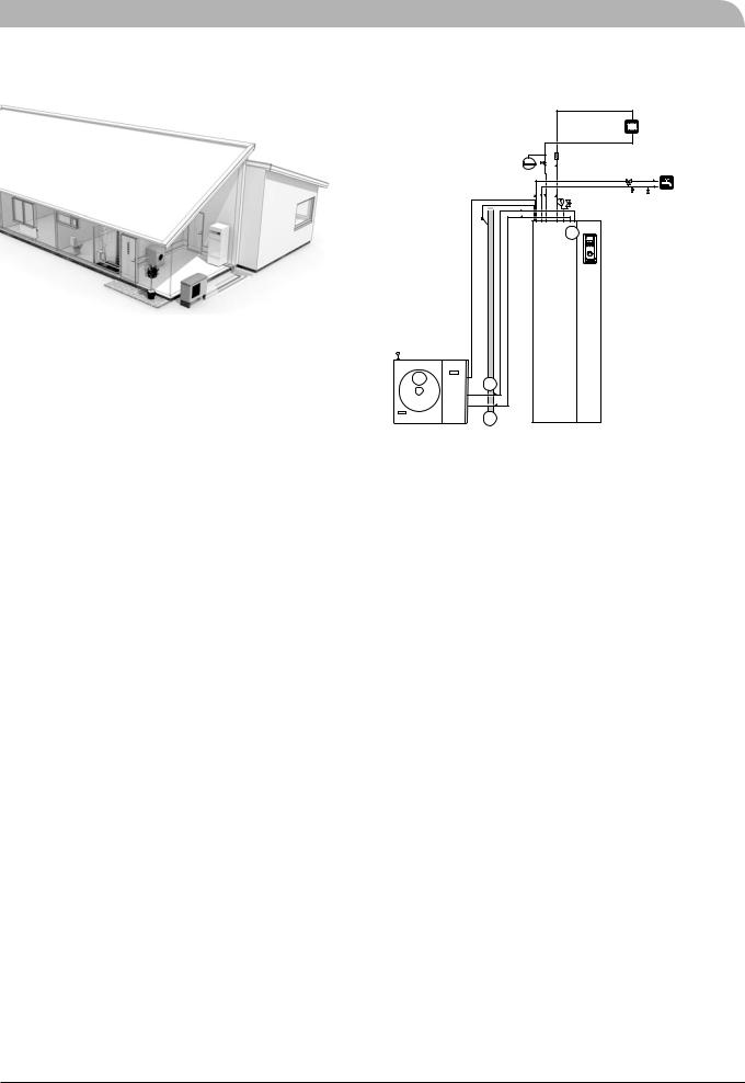
Principle of operation Hydrolution
Product information
Hydrolution is a complete modern heat pump system that offers effective technical energy saving and reduced carbon dioxide emissions. Heat production is safe and economical with integrated hot water heater, immersion heater, circulation pump and climate system in the indoor unit.
The heat is retrieved from the outdoor air through outdoor unit, where the refrigerant circulated in a closed piping system transfers the heat from the heat source (outdoor air) to indoor unit.
This eliminates the need for holes and coils in the ground.
Features of Hydrolution
■Optimal annual heating factor thanks to the inverter controlled compressor.
■Outdoor unit with compact dimensions.
■Speed controlled system pump that supplies the heat pump with suitable system flow.
■Optimized operating costs. The speed of the compressor is adjusted according to the demand.
■Integrated coil water heater in indoor unit.
■Integrated clock for scheduling extra hot water and temperature lowering/increasing the supply water temperature.
■Prepared for control of two heating systems.
■Integrated active cooling function.
■Possible to connect external heat sources.
|
3 |
1 |
2 |
|
|
|
4 |
Function
Hydrolution is a system that can produce heating, hot water and cooling.
The principle during heating can be simplified as follows:
1.The refrigerant in outdoor unit takes the heat from the outdoor air and is compressed to higher temperature by the compressor.
2.The hot refrigerant (now in gas state) is routed into indoor unit.
3.The refrigerant releases the heat for further distribution in the system.
4.The refrigerant (now in liquid state) is routed back to outdoor unit and the process is repeated.
By reversing the entire process, and thereby the refrigerant in outdoor unit takes the heat from the water and release the heat to the outdoor air, the heat pump can cool instead if necessary.
Indoor unit determines when outdoor unit is to work and not to work, using the collated data from the temperature sensor. In the event of extra heat demands, indoor unit can connect additional heat source in the form of the internal immersion heater, or any connected external heat source.

Front panel, indoor module
Front panel, indoor unit
Addition. heat symbol
If the electrical addition is connected
“I” Electrical step 1 “II” Electrical step 2
“I II” Electrical step 1+2
“III” Electrical step 3
Hot water symbol
Hot water charging in progress.
“A” Temporary Extra hot water operation in progress.
“B” Time based Extra hot water operation in progress, e.g. periodic.
Compressor symbol
- Compressor is operational “A” Heating mode “B” Cooling mode
Operating status
Button pressing (the change does not need to be confirmed with the enter button). - Current operating mode shown in display - Further button press changes operating mode. Press the enter button to return to the normal display mode.
For information about the various operating modes, see the different sections regarding comfort settings.
Extra hot water (XHW)
Extra hot water operation starts with this button. The operation is cancelled when the button is pressed again.
The change does not need to be confirmed with the Enter button.
Menu 1.0
Pressing the button takes you directly to menu 1.0.
Offset heating curve
- Turning clockwise (+) offsets the Heating curve. When the knob is turned
menu 2.0 is shown on the display and the value for the calculated supply temperature changes.
For details, see Default Heating curve setting.
Switch
1Normal mode
All control functions connected.
0 Shutdown

 Emergency mode
Only the circulation pump and electric heater (electrical step 2) are operational.
Circulation pump symbol
Circulation pump in operation.
With two circulation pumps (requires ESV 22 accessory), the operating pump is also indicated.
|
|
|
|
|
|
Heating system symbol |
|
|
|
|
|
|
|
|
|
|
|
|
|
|
A I II III A B |
I II |
Heating in progress. |
||||
|
|
|
|
|
|
|
|
|
|
|
|
|
|
|
|
|
|
|
|
|
|
5 0 . 0 ° C |
|
1.0 |
13.43 |
Description of current display |
|
|
parameter |
|
|
Information symbols |
|
|
1.0 Menu number |
|
|
Key lock activated. |
Plus button
- Scroll forward in the menu system.
- Increase the value of the selected parameter
See the section “Control – General”
Minus button
- Scroll back in the menu system.
- Reduce the value of the selected parameter
See the section “Control – General”
Enter button
- Entering lower layer in the menu system.
- Parameter change activated
- Parameter change confirmed
See the section “Control – General”
Status lamp
During normal operation, the status lamp lights green. In the event of an alarm, it lights red.
Front panel, indoor module
How to use the front panel
All the most common settings are made from the panel such as comfort etc. that you expect from the heat pump system to fulfil.
In order to make full use of it, certain basic settings must have been made (see page 10) and the installation in general is carried out according to the instructions.
Menu 1.0 (the temperature in the water heater) is normally shown on the display.
The plus and minus buttons and the enter button are used to scroll through the menu system as well as to change the set value in some menus.
Menu types (Menu 8.1.1)
Control is classified into different menu types depending on how “deep” into the controls you need to go.
■ |
Normal [N]: |
The settings you as a customer |
|
|
often need. |
■ |
Extended [U]: |
Shows all detailed menus except |
|
|
the service menus. |
Quick movement
To quickly return to the main menu from a sub menu, press the following button: 
Key lock
Akey lock can be activated in the main menus by simultaneously pressing the  and the
  buttons. The key symbol will then be shown on the display.
The same procedure is used to deactivate the key lock.
Language setting (Menu 8.1.2)
Language used in the display can be chosen in menu 8.1.2.

Comfort setting heating
General
The indoor temperature depends on several factors.
■Sunlight and heat emissions from people and household machines are normally sufficient to keep the house warm during the warmer parts of the year.
■When it gets colder outside, the heating system must be started. The colder it is outside, the warmer radiators and under floor heating systems must be.
Controlling heat production
Normally, the heat pump heats the water (heating medium) to the temperature required at a certain outdoor temperature. This occurs automatically on the basis of the collected temperature values from the outdoor sensor and sensors on the lines to the radiators (supply water sensors). Extra accessories such as room sensors, can influence the temperature.
In order to operate the system properly, the correct settings must be made on the heat pump first, see the section “Default Heating curve setting”.
The outdoor sensor (mounted on an exterior wall of the house) senses variations in the outdoor temperature early on, sends the information to the heat pump control computer and heating operation is started. It does not have to be cold inside the house before the control system is activated. As soon as the temperature drops outside, the temperature of the water to the radiators (supply temp.) inside the house is increased automatically.
The heat pumps flow temperature (menu 2.0) will hover around the theoretical required value, which is in brackets on the display.
Temperature of the heating system
The temperature of the heating system in relation to the outdoor temperature can be determined by you by selecting a heat curve and by using the “Offset heating curve” knob on the heat pump’s front panel.
Operating status
The “Operating mode” button is used to set the required  operating mode.
The change does not need to be confirmed with the enter button.
The current operating mode is shown on the front panel display when the button is pressed and the mode changes when you continue to press the button.
The display returns to the normal display mode once the enter button is pressed.
The electric heater is only used for anti-freeze if it is deactivated in the menu system for all operating modes.
There are different operating modes to choose:
Comfort setting heating
1.“Auto”
Indoor unit automatically selects the operating mode by taking the outdoor temperature into account. This means that the operating mode switches between "Heating" and “Hot water”.
The circulation pump is permitted to operate when there is a need.
2.“AutoC”*
Indoor unit selects operating mode automatically (cooling can also be selected now) by the outdoor temperature. This means that the operating mode switches between “Heating”, “Cooling” and “Hot water”.
The circulation pump is permitted to operate when there is a need.
3.Heating
Only heating and hot water mode.
The circulation pump is in operation the entire time. Electirc heater is energized if necessary.
4.Cooling*
Heat pump is used for cooling only if electric heater use is allowed. Otherwise, it is used for both cooling and hot water. The circulation pump is in operation the entire time.
5.Hot water
Only hot water is produced.
Only the compressor is operational.
6.Add. Heat only
Heat pump is not operational. The function is activated/ deactivated by pressing in the “operating mode button” for 7 seconds.
* To use the cooling functions, the system must be designed to withstand low temperatures and cooling must be activated in menu 9.3.3.
Changing the room temperature manually
If you want to temporarily or permanently increase or lower the indoor temperature, turn the “Offset heating curve” knob
clockwise to increase or anticlockwise to lower. One line approximately represents 1 degree change in room temperature.
NOTE
An increase in the room temperature may be inhibited by the radiator or underfloor heating thermostats, if so these must be set at 0.
Comfort setting heating
Default Heating curve setting
The basic heating is set using menu 2.1.2 and with the “Heating curve offset” knob.
If the room temperature does not reach the target, readjustment may be necessary.
If you do not know the correct settings, use the basic data from the automatic heating control system diagram on the right.
9 |
Heating curve 2 . 1 . 2
|
|
|
|
Menu 2.1.2 Heating curve |
Offset heating curve |
||
Heating curve offset for system 2 can be made in menu 3.1
NOTE
Wait one day between settings so as to stabilise the temperatures.
Setting with diagrams
The diagram shows the relation between the outdoor temperature in the area and the target supply water temperature of the heating system. This is set under menu 2.1.2, “Heating curve”. Limitations, which are not in the diagrams, can be set in the control system’s permitted min and max temperatures. (See menu 2.1.4 and 2.3 as well as 3.3 and 3.4)
Heating curve offset -2
|
|
|
|
HEATING |
|||
|
|
|
|
|
|
VÄRMEKUCURVEA |
|
FRAMLEDNINGSTEMPERATUR Supply |
C |
|
|
15 14 13 |
12 |
11 |
3 |
|
70 |
|
|
10 |
|||
|
|
|
|
|
|
9 |
|
|
|
|
|
|
|
|
|
temperature |
60 |
|
|
|
|
|
8 |
|
|
|
|
|
|
||
|
|
|
|
|
|
|
|
|
|
|
|
|
|
|
7 |
|
50 |
|
|
|
|
|
6 |
|
|
|
|
|
|
|
5 |
|
40 |
|
|
|
|
|
4 |
|
30 |
|
|
|
|
|
2 |
+ 5 |
|
|
|
|
|
|
|
|
|
|
|
|
|
1 |
|
|
|
|
|
|
|
|
|
|
10 |
0 |
- 10 |
- 20 |
|
- 30 |
- 40 C |
- 5  FÖRSKJUTNINGOutdoor temperature UTETEMPERATUR OFFSET HEAT CURVEVÄ M KURVA (-2)
Heating curve offset 0
|
|
|
|
|
HEATING |
|||
|
|
|
|
|
|
VÄRMEKUCURVEA |
||
FRAMLEDNINGSTEMPERATUR Supply |
C |
|
15 14 13 |
12 |
11 |
10 |
9 |
|
70 |
|
|||||||
|
|
|||||||
|
|
|
|
|
|
|
|
|
temperature |
|
|
|
|
|
|
|
8 |
60 |
|
|
|
|
|
|
7 |
|
|
|
|
|
|
|
|
||
|
50 |
|
|
|
|
|
|
6 |
|
|
|
|
|
|
|
5 |
|
|
|
|
|
|
|
|
|
|
|
40 |
|
|
|
|
|
|
4 |
|
|
|
|
|
|
|
3 |
|
|
|
|
|
|
|
|
|
|
|
30 |
|
|
|
|
|
|
2 |
|
|
|
|
|
|
|
|
|
+ 5 |
|
|
|
|
|
|
|
1 |
|
10 |
0 |
- 10 |
- 20 |
- 30 |
|
- 40 C |
|
- 5  FÖRSKJUTNINGOutdoor temperature UTETEMPERATUR OFFSET HEAT CURVEVÄ M KURVA (0)
Heating curve offset +2
|
|
|
|
|
HEATING |
||
|
|
|
|
|
|
VÄRMEKUCURVEA |
|
FRAMLEDNINGSTEMPERATUR Supply |
C |
|
1514 13 |
12 |
11 |
10 |
2 |
|
70 |
|
9 |
||||
|
|
|
|
|
|
8 |
|
|
|
|
|
|
|
|
|
temperature |
60 |
|
|
|
|
|
7 |
|
|
|
|
|
4 |
||
|
|
|
|
|
|
|
6 |
|
50 |
|
|
|
|
|
5 |
|
|
|
|
|
|
|
|
|
40 |
|
|
|
|
|
3 |
|
30 |
|
|
|
|
|
1 |
+ 5 |
|
|
|
|
|
|
|
|
|
|
|
|
|
|
|
|
10 |
0 |
- 10 |
- 20 |
- 30 |
- 40 C |
|
- 5  FÖRSKJUTNINGOutdoor temperature UTETEMPERATUR OFFSET HEAT CURVEVÄ M KURVA (+2)
10
 Loading...