


MasterChef H 397 B2
Miele MasterChef H 397 B2, MasterChef H 395 B, MasterChef H 397 BP2, MasterChef H 398 BP2, MasterChef H 398 B2 Technical Information
...
TECHNICAL INFORMATION
MasterChef Ovens
© 2011 Miele USA

MasterChef Ovens
Technical Information
Table of Contents
1.0 Construction and Design ......................................................................................... 6
1.1 Summary of Model Numbers ...................................................................................... 6
1.1.1 H 39x MasterChef Ovens ........................................................................................ 6
1.1.2 H 39x MasterChef Warming Drawers ...................................................................... 6
1.1.3 H 4xxx MasterChef Ovens ....................................................................................... 6
1.1.4 H 4xxx MasterChef Warming Drawers .................................................................... 7
1.1.5 EBA Filler Strips ....................................................................................................... 7
1.2 Appliance Overview .................................................................................................... 8
1.2.1 Single Oven (Typical) .............................................................................................. 8
1.2.2 Double Oven (Typical) ............................................................................................. 9
1.3 Overview of User Controls ........................................................................................ 10
1.3.1 H 39x Single Oven Controls .................................................................................. 10
1.3.2 H 39x Double Oven Controls ................................................................................. 10
1.3.3 H 4xxx Single Oven Controls ................................................................................. 11
1.3.4 H 4xxx Double Oven Controls ............................................................................... 11
1.4 Component Overviews .............................................................................................. 12
1.4.1 H 39x B Single Oven (w/o Self-Clean or MasterChef Menu) ................................ 12
1.4.2 H 39x BP Single Oven (w/Self-Clean) ................................................................... 13
1.4.3 H 39x B2 Double Oven (w/o Self-Clean) ............................................................... 14
1.4.4 H 39x BP2 Double Oven (w/Self-Clean) ................................................................ 15
1.4.5 H 468x B Single Oven (w/o Self-Clean) ................................................................ 17
1.4.6 H 478x B/BP Single Oven (with/without Self-Clean) ............................................. 18
1.4.7 H 488x B/BP Single Oven (with/without Self-Clean) ............................................. 19
1.4.8 H 489x B2/BP2 Double Oven (with/without Self-Clean) ........................................ 20
2.0 Installation ............................................................................................................... 22
2.1 Installation Manual .................................................................................................... 22
2.2 Installation Guide ...................................................................................................... 23
3.0 Commission and Operation ................................................................................... 24
3.1 General Operation .................................................................................................... 24
3.1.1 Selecting and Starting a Program .......................................................................... 24
3.1.2 Turning Off the Appliance ...................................................................................... 24
3.2 Power Failures .......................................................................................................... 24
3.3 Special Features ....................................................................................................... 24
3.3.1 Self-Clean Function (“P” Models Only) .................................................................. 24
3.3.2 Door Lock (“P” Models Only) ................................................................................. 25
3.3.3 MasterChef (Where Applicable) ............................................................................ 25
3.3.4 Child Safety Lock (All Models) ............................................................................... 25
4.0 Description of Function .......................................................................................... 26
4.1 Cooling Air Intake ..................................................................................................... 27
4.2 Vapor Intake ............................................................................................................. 27
4.3 Cooling Air Path ........................................................................................................ 27
4.4 Cooling Air Exit ......................................................................................................... 27
4.5 Door Contact Switch ................................................................................................. 27
4.6 Heater Elements ....................................................................................................... 27
4.6.1 Heater Element Activation ..................................................................................... 28
4.7 Automatic/Safety Shutdown ...................................................................................... 28
4.8 Oven Cavity Temperature Sensor ............................................................................ 29
4.9 Roast Probe .............................................................................................................. 29
4.10 Self-Clean Temperature Sensor (“P” Models Only) .................................................. 29
4.11 Oven Cavity Thermostat ........................................................................................... 30
2
MasterChef Ovens
Technical Information
4.12 Self-Clean Thermostat (“P” Models Only) ................................................................. 30
4.13 Convection Fan ......................................................................................................... 30
4.14 Rotisserie Motors ...................................................................................................... 31
4.15 Oven Cavity Lights .................................................................................................... 31
4.16 Automatic Door Lock (“P” Models Only) .................................................................... 31
5.0 Service and Maintenance ....................................................................................... 32
5.1 Cleaning and Care Information ................................................................................. 32
5.1.1 PerfectClean® ........................................................................................................ 32
5.1.2 Manually Cleaning the Oven Cavity ...................................................................... 32
5.2 Door Removal ........................................................................................................... 33
5.2.1 H 39x, H 488x, H 489x ........................................................................................... 33
5.2.2 H 468x, H 478x ...................................................................................................... 33
5.3 Runner Removal ....................................................................................................... 34
5.3.1 H 39x, H 488x, H 489x ........................................................................................... 34
5.3.2 H 468x.................................................................................................................... 34
5.3.3 H 478x.................................................................................................................... 35
5.4 Halogen Light Bulb Replacement ............................................................................. 35
5.5 Removing the Appliance for Service ......................................................................... 36
5.6 Control Panel Removal ............................................................................................. 37
5.7 Safety Cover Removal .............................................................................................. 38
5.8 Top Cover Removal (H 39x, H 488x, H 489x) ........................................................... 38
5.9 Front/Rear Cover Plate Removal (H 478x Only) ....................................................... 38
5.10 Front/Middle/Rear Cover Plate Removal (H 468x Only) ........................................... 39
5.11 Upper Rear Panel Removal (Double Ovens Only) .................................................... 40
5.12 Lower (or Single Oven) Rear Panel Removal ........................................................... 40
5.13 Side Cover Removal ................................................................................................. 40
5.14 Air Shield Panel Removal (Double Ovens Only) ....................................................... 40
5.15 Upper (or Single Oven) Cooling Fan Removal .......................................................... 41
5.16 Lower Oven Cooling Fan Removal (Double Ovens Only) ......................................... 41
5.17 Door Latch Manual Release (“P” Models Only) ........................................................ 42
5.18 Upper Door Lock Motor and Switch Removal (P-Model Double Ovens Only) .......... 43
5.19 Lower Door Lock Motor and Switch Removal (P-Model Double Ovens Only) .......... 44
5.20 Upper (or Single Oven) Door Latch, Door Lock Switch and Door Closed Switch
Access (“P” Models Only) ......................................................................................... 44
5.21 Lower Door Latch, Door Lock Switch and Door Closed Switch Access (P-Model
Double Ovens Only).................................................................................................. 46
5.22 Oven Cavity Back Panel Removal ............................................................................ 47
5.23 Top Heater/Broiler Element (R13/R15) Removal ...................................................... 47
5.23.1H 39x/H 488x ......................................................................................................... 47
5.23.2H 468x/H 478x ....................................................................................................... 48
5.24 Convection Heater Element (R14) Removal ............................................................. 48
5.25 Convection Fan (M2/2) Removal .............................................................................. 49
5.26 Cavity Temperature Sensor Removal ....................................................................... 50
5.27 Self-Clean Thermostat Removal (“P” Models Only) .................................................. 50
5.28 Self-Clean Thermostat Resistance Values ............................................................... 51
5.29 Rotisserie Motor (M15) Removal .............................................................................. 51
5.30 Catalyst Insert Removal (“P” Models Only) ............................................................... 52
5.31 Door Disassembly/Glass Removal (H 468x B) ......................................................... 53
5.32 Door Outer Glass Pane Removal (H 39x, H 478x and H 488x) ................................ 54
5.33 Door Middle Glass Pane Removal (H 39x, H 478x and H 488x) ............................... 55
5.34 Door Inner Glass Pane Removal (H 39x, H 478x and H 488x) ................................. 55
5.35 Door Hinge Removal................................................................................................. 56
5.35.1H 39x, H 488x, H 489x ........................................................................................... 56
3

MasterChef Ovens
Technical Information
5.35.2H 478x.................................................................................................................... 57
5.35.3H 468x.................................................................................................................... 58
6.0 Fault Diagnosis ....................................................................................................... 59
6.1 Electronics Overview ................................................................................................ 59
6.1.1 H 39x Models ......................................................................................................... 59
6.1.2 H 4xxx Models ....................................................................................................... 60
6.2 Fault Code Summary ................................................................................................ 60
6.3 Programming Mode .................................................................................................. 61
6.4 Service Mode ............................................................................................................ 63
6.5 Temperature Test ..................................................................................................... 65
6.5.1 Test Equipment ...................................................................................................... 65
6.5.2 Test Procedure ...................................................................................................... 65
List of Figures
Figure 1-1: Overview of Single Oven ...................................................................................... 8
Figure 1-2: Overview of Double Oven ..................................................................................... 9
Figure 1-3: Overview of H 39x Single Oven Controls ............................................................ 10
Figure 1-4: Overview of H 39x Double Oven Controls .......................................................... 10
Figure 1-5: Overview of H 4xxx Single Oven Controls .......................................................... 11
Figure 1-6: Overview of H 4xxx Double Oven Controls ......................................................... 11
Figure 1-7: Single Oven, no Self-Clean or MasterChef (H 394 B Shown) ............................. 12
Figure 1-8: Single Oven w/Self-Clean (H 396 BP Shown) .................................................... 13
Figure 1-9: Double Oven w/o Self-Clean (H 398 B2 Shown) ................................................ 14
Figure 1-10: Double Oven w/Self-Clean (H 398 BP2 Shown) ............................................... 15
Figure 1-11: H 468x B ........................................................................................................... 17
Figure 1-12: H 478x B/BP ..................................................................................................... 18
Figure 1-13: H 488x B/BP ..................................................................................................... 19
Figure 1-14: H 489x B2/BP2 ................................................................................................. 20
Figure 2-1: Miele Installation Information Manual for Residential Appliances ....................... 22
Figure 2-2: Installation Guide (Included with Each Oven) ..................................................... 23
Figure 3-1: ”Power Failure” Message (H 39x Display Shown) .............................................. 24
Figure 3-2: Child Safety Lock ................................................................................................ 25
Figure 4-1: Airflow Paths (Double Oven Shown) ................................................................... 26
Figure 4-2: Upper Heater Element Cavity Temperature Sensor ........................................... 29
Figure 4-3: Roast Probe ........................................................................................................ 29
Figure 4-4: Self-Clean Temperature Sensor (1) and Catalyst Vapor Outlet (2) ..................... 30
Figure 4-5: Convection Airflow .............................................................................................. 3
Figure 4-6: Door Locking Components (“P” Models Only) .................................................... 31
Figure 5-1: Door Hinge Locking Tabs ................................................................................... 33
Figure 5-2: Hinge Locking Tab in Released Position to Allow Door Removal ....................... 33
Figure 5-3: Runner Removal (H 39x, H 488x, H 489x) .......................................................... 34
Figure 5-4: Runner Release (H 468x) ................................................................................... 34
Figure 5-5: Runner Removal (H 468x) .................................................................................. 34
Figure 5-6: Runner Release (H 478x) ................................................................................... 35
Figure 5-7: Runner Removal (H 478x) .................................................................................. 35
Figure 5-8: Prying Off the Light Cover ................................................................................... 35
Figure 5-9: Sliding the Light Cover Out ................................................................................. 36
Figure 5-10: Installation Screws ............................................................................................ 37
Figure 5-11: Control Panel Retaining Screws ....................................................................... 37
Figure 5-12: Safety Cover Retaining Screws ........................................................................ 38
0
4

MasterChef Ovens
Technical Information
Figure 5-13: Front Cover Plate (H 478x) ............................................................................... 39
Figure 5-14: Rear Cover Plate (H 478x) ................................................................................ 39
Figure 5-15: Air Shield Panel ................................................................................................ 40
Figure 5-16: Upper (or Single Oven) Cooling Fan Removal .................................................. 41
Figure 5-17: Lower Oven Cooling Fan Removal ................................................................... 42
Figure 5-18: Door Latch Manual Release (“P” Models Only) ................................................ 43
Figure 5-19: Door Lock Motor Assembly ............................................................................... 43
Figure 5-20: Door Lock Motor and Bowden Cable ................................................................ 44
Figure 5-21: Safety Cover Retaining Screws ........................................................................ 45
Figure 5-22: Accessing the Door Latch Assembly and Door Closed Switch ......................... 46
Figure 5-23: Door Latch Assembly ........................................................................................ 46
Figure 5-24: Removing the Oven Cavity Back Panel ............................................................ 47
Figure 5-25: Top Heater/Broiler Element .............................................................................. 48
Figure 5-26: Convection Element and Fan ............................................................................ 49
Figure 5-27: Convection Fan Retaining Screws .................................................................... 50
Figure 5-28: Self-Clean Thermostat Removal ....................................................................... 51
Figure 5-29: Rotisserie Motors and Screws .......................................................................... 52
Figure 5-30: Catalyst Insert Removal .................................................................................... 53
Figure 5-31: Top View of H 468x Door, Showing Cover Strip and Retaining Screws ........... 53
Figure 5-32: Inner Panel Removal (H 468x) .......................................................................... 53
Figure 5-33: Middle Panel Removal (H 468x) ....................................................................... 54
Figure 5-34: Door Outer Glass Pane Removal (H 39x, H 478x, H 488x) .............................. 54
Figure 5-35: Door Middle Glass Pane Removal (H 478x) ..................................................... 55
Figure 5-36: Door Middle Glass Pane Removal (H 39x and H 488x) .................................... 55
Figure 5-37: Door Inner Glass Pane Removal (H 39x, H 478x, H 488x) ............................... 56
Figure 5-38: Door Hinge Removal (H 39x, H 488x)............................................................... 57
Figure 5-39: Hinge Removal, Part 1 (H 478x) ....................................................................... 57
Figure 5-40: Hinge Removal, Part 2 (H 478x) ....................................................................... 58
Figure 5-41: Hinge Removal (H 468x) ................................................................................... 58
Figure 6-1: Overview of H 39x Series Electronic Boards ...................................................... 59
Figure 6-2: Overview of H 4xxx Series Electronic Boards ..................................................... 60
List of Tables
Table 1-1: Summary of H 39x MasterChef Ovens .................................................................. 6
Table 1-2: Summary of H 39x MasterChef Warming Drawers ................................................ 6
Table 1-3: Summary of H 4xxx MasterChef Ovens ................................................................. 7
Table 1-4: Summary of H 4xxx MasterChef Warming Drawers ............................................... 7
Table 1-5: Summary of EBA Filler Strips ................................................................................. 7
Table 4-1: Heater Element Specifications (H 39x Ovens) ..................................................... 27
Table 4-2: Heater Element Specifications (H 4xxx Ovens) ................................................... 27
Table 4-3: Heater Element Operation ................................................................................... 28
Table 4-4: Automatic Safety Shutdown Durations ................................................................. 28
Table 5-1: Self-Clean Thermostat Resistance Values ........................................................... 51
Table 6-1: Fault Codes .......................................................................................................... 60
Table 6-2: Programming Mode ............................................................................................. 63
Table 6-3: Service Mode ....................................................................................................... 64
5
Technical Information
1.0 Construction and Design
1.1 Summary of Model Numbers
1.1.1 H 39x MasterChef Ovens
Model
Number
H 394 B
H 395 B
Oven Type Size (Width)
Single
(w/o MasterChef menu)
MasterChef Ovens
H 395 BP
H 396 B
H 396 BP
H 397 B2
H 397 BP2
H 398 B2
H 398 BP2
Table 1-1: Summary of H 39x MasterChef Ovens
Single
Double
1.1.2 H 39x MasterChef Warming Drawers
Model Number Finish Size (Width)
ESW 700-25
ESW 700-25 FB1
ESW 760-25
ESW 760-25 FB1
ESW 761-25
ESW 762-25
ESW 763-25
Table 1-2: Summary of H 39x MasterChef Warming Drawers
1 For use with custom panel
Black, white or stainless steel 27”
Black, white or stainless steel
“U” design - stainless steel or white
Stainless steel with Profi handle
“U” design - stainless steel with Profi handle
1.1.3 H 4xxx MasterChef Ovens
Model Number Oven Type Size (Width)
H 4680 B
H 4682 B
H 4780 B
H 4780 BP
H 4782 BP
Single
30” (all models)
30”
60cm
70cm
6
MasterChef Ovens
Model Number Oven Type Size (Width)
H 4880 B
H 4880 BP
H 4881 B
H 4881 BP
H 4882 BP
H 4890 B2
H 4890 BP2
H 4892 BP2
Table 1-3: Summary of H 4xxx MasterChef Ovens
Single
Double
1.1.4 H 4xxx MasterChef Warming Drawers
Model Number Finish Size (Width)
ESW 4082-14
ESW 4700 FB1
ESW 4701 FB1
ESW 4702 FB1
ESW 4710
ESW 4711
ESW 4712
ESW 4720
ESW 4721
ESW 4722
ESW 4800 FB1
ESW 4801 FB1
ESW 4802 FB1
ESW 4810
ESW 4811
ESW 4812
ESW 4820
ESW 4821
ESW 4822
Table 1-4: Summary of H 4xxx MasterChef Warming Drawers
1
For use with custom panel
Stainless steel 60cm
Stainless steel
Stainless steel
Stainless steel
Stainless steel
Stainless steel
Stainless steel
Black
Black
Black
Stainless steel
Stainless steel
Stainless steel
Stainless steel
Stainless steel
Stainless steel
Black
Black
Black
1.1.5 EBA Filler Strips
Used when installing other Miele products with H 4xxx ovens.
Model Number Product Usage
EBA4370
EBA4470
EBA4376
EBA4476
Table 1-5: Summary of EBA Filler Strips
Install CVA 266x into 70cm opening
Install H 4080 or DG 4080 into 70cm opening
Install CVA 266x into 30” opening
Install H 4080 or DG 4080 into 30” opening
Technical Information
30”
70cm
30”
7
Technical Information
1.2 Appliance Overview
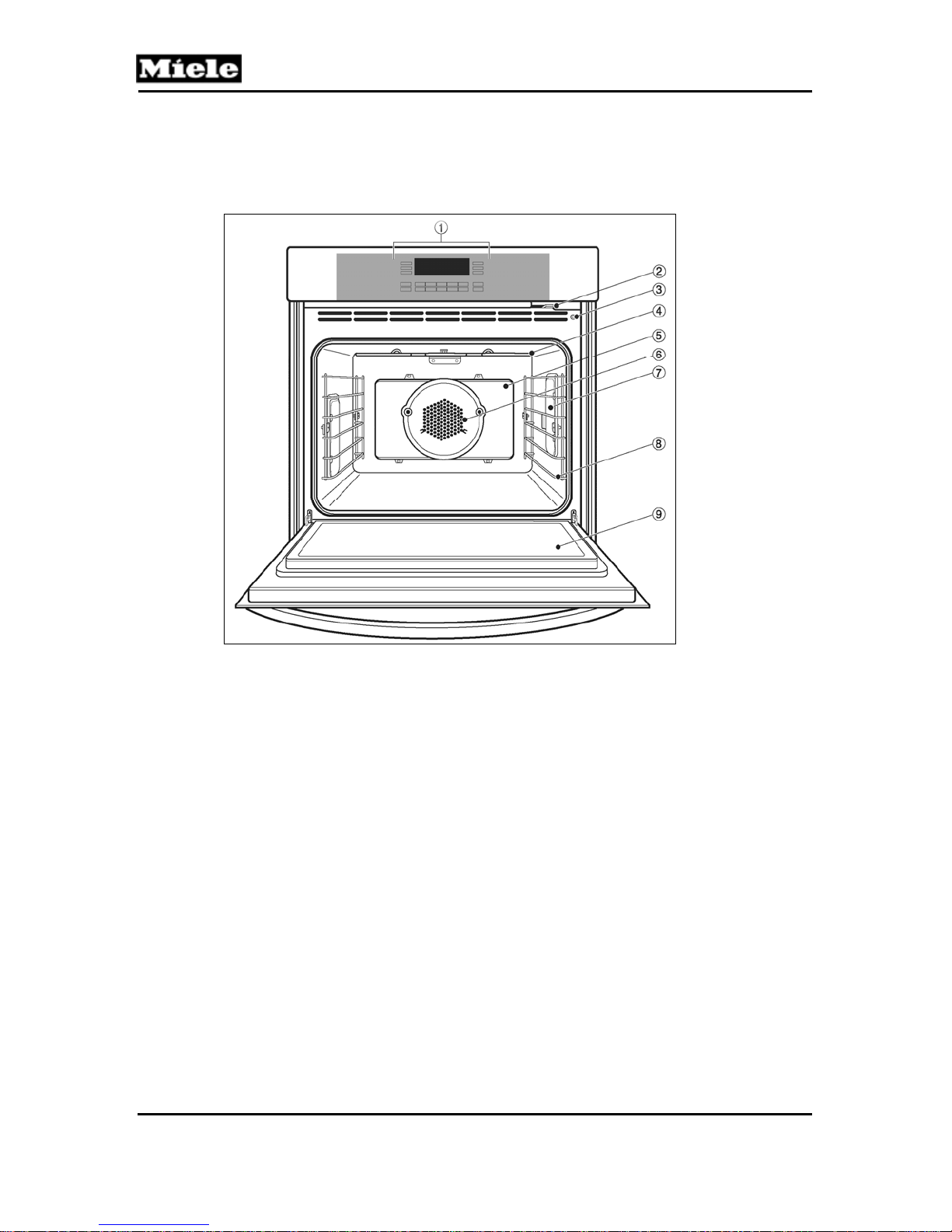
1.2.1 Single Oven (Typical)
MasterChef Ovens
Figure 1-1: Overview of Single Oven
1
Control panel
2
Child safety lock
3
Door contact switch
4
Upper heating element
5
Catalytic liner
6
Convection fan
7
Light
8
Six non-tip level runners
9
Oven door
8

MasterChef Ovens
1.2.2 Double Oven (Typical)
Technical Information
Figure 1-2: Overview of Double Oven
1
Control panel
2
Door lock
3
Child safety lock
4
Door contact switch
5
Upper heater element
6
Rotisserie motors
7
Light
8
Roast probe socket
9
Convection fan
10
Six level runners
11
Oven door
9
Technical Information
1.3 Overview of User Controls
1.3.1 H 39x Single Oven Controls
MasterChef Ovens
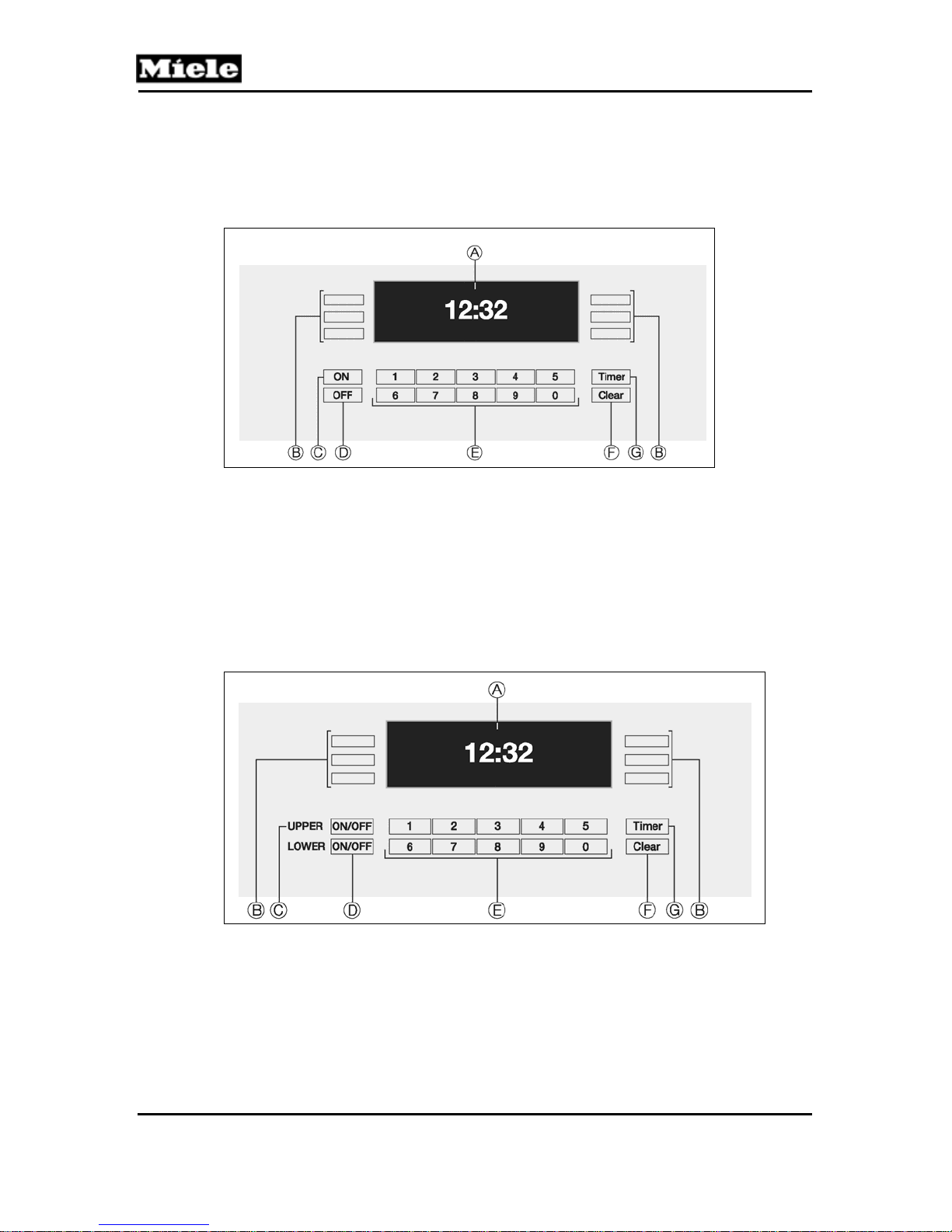
Figure 1-3: Overview of H 39x Single Oven Controls
A Display: shows the time or the functions.
B Touch controls: to select or set a function.
C ON: to turn the oven on.
D OFF: to turn the oven off.
E Keypad: to enter times or temperatures.
F Clear: to delete the last entry or to clear menu items.
G Timer: to set a timer independent of an oven function.
1.3.2 H 39x Double Oven Controls
Figure 1-4: Overview of H 39x Double Oven Controls
A Display: shows the time, oven status, or menu options.
B Touch controls: used to select an option
C ON/OFF: turns the upper oven on/off.
D ON/OFF: turns the lower oven on/off.
E Keypad: used to enter times or temperatures.
F Clear: deletes the last entry or clears the menu.
G Timer: used to set up to 2 independent cooking timers.
10

MasterChef Ovens
1.3.3 H 4xxx Single Oven Controls
Technical Information
Figure 1-5: Overview of H 4xxx Single Oven Controls
1.3.4 H 4xxx Double Oven Controls
Figure 1-6: Overview of H 4xxx Double Oven Controls
11
MasterChef Ovens
Technical Information
1.4 Component Overviews
1.4.1 H 39x B Single Oven (w/o Self-Clean or MasterChef Menu)
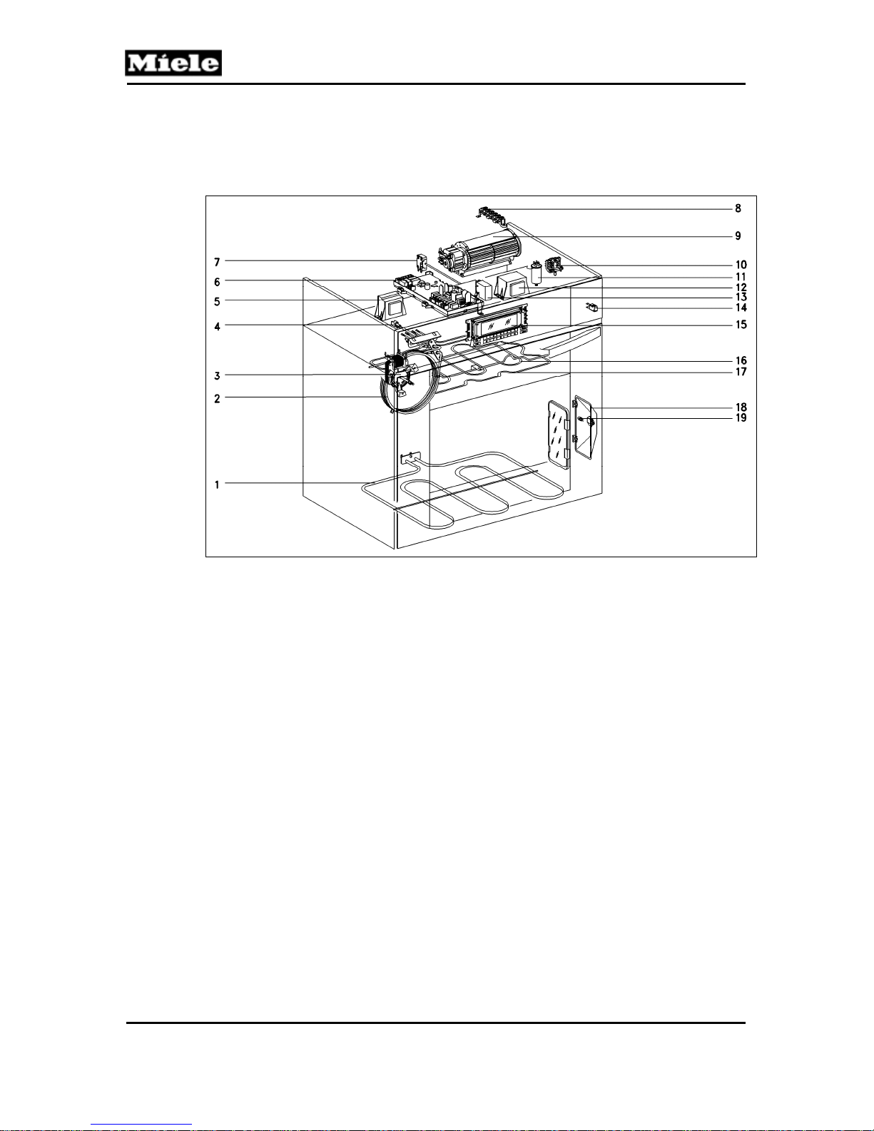
Figure 1-7: Single Oven, no Self-Clean or MasterChef (H 394 B Shown)
1
(1R12) Lower heating element
2
(1R14) Convection heating element
3
(1M2/2) Convection fan
4
(1R30) Oven temperature sensor
5
(2T1) Lighting transformer
6
(1N1) Power electronic
7
(1F1) Oven cavity thermostat
8
(X3/1) Terminal block
9
(1M2/1) Cooling fan
10
(S1) Child safety lock
11
(Z2) Interference suppression capacitor
12
(1T1) Transformer
13
(1K1) Oven relay
14
(1S24) Door switch
15
(1A1, 2A1) Display electronic
16
(1R15) Broiler element
17
(1R13) Upper heating element
18
(1H3/1, 2H3/1) Light assembly (1 per side)
19
Halogen bulb
12

MasterChef Ovens
1.4.2 H 39x BP Single Oven (w/Self-Clean)
Technical Information
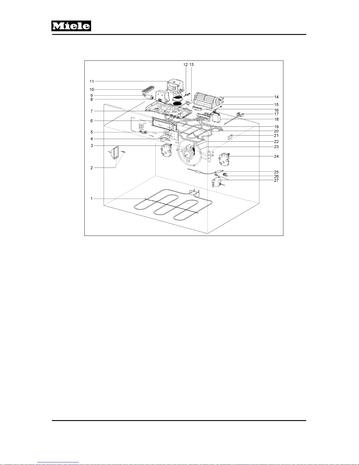
Figure 1-8: Single Oven w/Self-Clean (H 396 BP Shown)
1
(1R12) Lower heating element
2
(1R14) Convection heating element
3
(1M2/2) Convection fan
4
(1M15, 2M15) Rotisserie motors
5
(1R30) Oven cavity temperature sensor
6
(2T1) Lighting transformer
7
(3R30) Pyrolytic PTC sensor (“P” models only)
8
(1N1) Power electronic
9
(2F1) Self-clean thermostat (“P” models only)
10
(1S60) Interlock switch
11
(1F1) Oven cavity thermostat
12
(1M23) Door lock motor (“P” models only)
13
(X3/1) Terminal block
14
(1M2/1) Cooling fan
15
(S1) Child safety lock
16
(Z2) Interference suppression capacitor
17
(1T1) Transformer
18
(1K1) Oven relay
19
(2S60) Interlock switch
20
(1S24) Door switch
21
(1A1, 2A1) Display electronic
22
(1R15) Broiler element
23
(1R13) Upper heating element
24
(1X5/8) Roast probe socket
25
(2R30) Roast probe
26
Halogen bulb
27
(1H3/1, 2H3/1) Light assembly
13

Technical Information
1.4.3 H 39x B2 Double Oven (w/o Self-Clean)
MasterChef Ovens
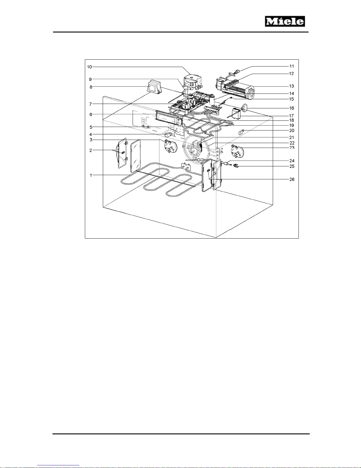
Figure 1-9: Double Oven w/o Self-Clean (H 398 B2 Shown)
1
(2R12) Lower oven lower heating element
2
(2R14) Lower oven convection heating element
3
(2M2/2) Lower oven convection fan
4
(4R30) Lower oven cavity temperature sensor
5
(3F1) Lower oven cavity thermostat
6
(2M2/1) Lower oven cooling fan
7
(1R12) Upper oven lower heating element
8
(1R14) Upper oven convection heating element
9
(1M2/2) Upper oven convection fan
10
(1M15, 2M15) Rotisserie motors
11
(1R30) Upper oven cavity temperature sensor
12
(2T1) Upper oven lighting transformer
13
(3T1) Lower oven lighting transformer
14
(1N1) Power electronic
15
(1F1) Upper oven cavity thermostat
16
(X3/1) Terminal block
17
(1M2/1) Upper oven cooling fan
18
(1K1) Upper oven relay
19
(2K1) Lower oven relay
20
(S1) Child safety lock
14

MasterChef Ovens
21
(Z2) Interference suppression capacitor
22
(1T1) Transformer
23
(1S24) Upper oven door switch
24
(1A1, 2A1) Display electronic
25
(1R15) Upper oven broiler element
26
(1R13) Upper oven upper heating element
27
(1H3/1, 2H3/1) Upper oven light assembly
28
Upper oven halogen bulb
29
(1X5/8) Upper oven roast probe socket
30
(2R30) Upper oven roast probe
31
(2S24) Lower oven door switch
32
(2R13) Lower oven upper heating element
33
(2R15) Lower oven broiler element
34
Lower oven halogen bulb
35
(2X5/8) Lower oven roast probe socket
36
(3H3/1, 4H3/1) Lower oven light assembly
37
(5R30) Lower oven roast probe
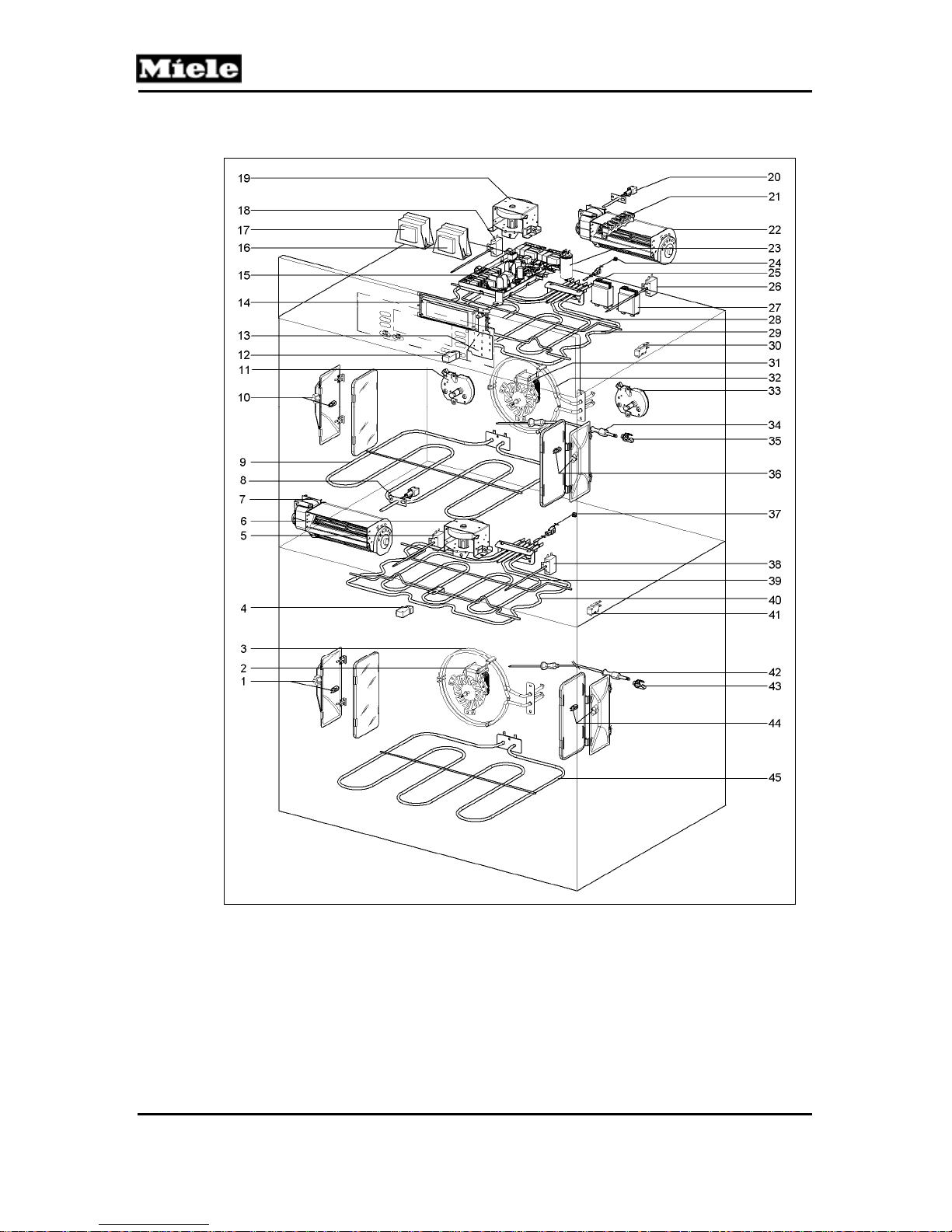
1.4.4 H 39x BP2 Double Oven (w/Self-Clean)
Technical Information
Figure 1-10: Double Oven w/Self-Clean (H 398 BP2 Shown)
15

Technical Information
1
(2R12) Lower oven lower heating element
2
(2R14) Lower oven convection heating element
3
(2M2/2) Lower oven convection fan
4
(4R30) Lower oven cavity temperature sensor
5
(3F1) Lower oven cavity thermostat
6
(4F1) Lower oven self-clean thermostat
7
(6R30) Lower oven catalyst temperature sensor
8
(2M2/1) Lower oven cooling fan
9
(3S60) Lower oven interlock switch
10
(2M23) Lower oven door lock motor
11
(1R12) Upper oven lower heating element
12
(1R14) Upper oven convection heating element
13
(1M2/2) Upper oven convection fan
14
(1M15, 2M15) Upper oven rotisserie motors (2)
15
(1R30) Upper oven cavity temperature sensor
16
(2T1) Upper oven lighting transformer
17
(3T1) Lower oven lighting transformer
18
(3R30) Upper oven catalyst temperature sensor
19
(1N1) Power electronic
20
(1F1) Upper oven cavity thermostat
21
(1S60) Upper oven interlock switch
22
(2F1) Upper oven self-clean thermostat
23
(1M23) Upper oven door lock motor
24
(X3/1) Terminal block
25
(1M2/1) Upper oven cooling fan
26
(1K1) Upper oven relay
27
(2K1) Lower oven relay
28
(S1) Child safety lock
29
(Z2) Interference suppression capacitor
30
(1T1) Transformer
31
(2S60) Upper oven interlock switch
32
(1S24) Upper oven door switch
33
(1A1, 2A1) Display electronic
34
(1R13) Upper oven upper heating element
35
(1R15) Upper oven broiler element
36
(1H3/1, 2H3/1) Upper oven light assembly
37
Upper oven halogen bulb
38
(1X5/8) Upper oven roast probe socket
39
(2R30) Upper oven roast probe
40
(2S24) Lower oven door switch
41
(4S60) Lower oven interlock switch
42
(2R13) Lower oven upper heating element
43
(2R15) Lower oven broiler heating element
44
Lower oven halogen bulb
45
(2X5/8) Lower oven roast probe socket
46
(3H3/1, 4H3/1) Lower oven light assembly
47
(5R30) Lower oven roast probe
MasterChef Ovens
16

MasterChef Ovens
1.4.5 H 468x B Single Oven (w/o Self-Clean)
Technical Information
Figure 1-11: H 468x B
1
(R12) Lower heating element
2
(R14) Convection element
3
(M2/2) Convection fan
4
(K1/1) Oven relay
5
(Z1) Interference suppression capacitor
6
(X3/1) Terminal block
7
(1T1) Transformer
8
(1F1) Oven cavity thermostat (419°F/215°C)
9
(M15) Grill motor with switch (S77)
10
(1R30) Oven cavity temperature sensor
11
(R13) Upper heating element
12
(R15) Broiler element
13
(M2/1) Cooling fan
14
(1N1) Power electronic EPL
15
(1A1) Control electronic EPX
16
(2A1) Selection electronic EW
17
(2R30) Roast probe
18
(X5/8) Roast probe socket
19
(1H3/1, 2H3/1) Light assembly
20
(S24) Door contact switch
17
Technical Information
1.4.6 H 478x B/BP Single Oven (with/without Self-Clean)
MasterChef Ovens
Figure 1-12: H 478x B/BP
1
(R12) Lower heater element
2
(1H3/1) Light assembly
3
(1M15) Rotisserie motor
4
(2S60) Door lock position switch
5
(2A1) Selection electronic EW
6
(1A1) Control electronic EPX
7
(1N1) Power electronic EPL
8
(T1) Light transformer
9
(Z2) Interference suppression capacitor
10
(X3/1) Terminal block
11
(M23) Door lock motor (“P” models only)
12
(2R30) Catalyst PT 1000 temperature sensor (“P” models only)
13
(2F1) Self-clean thermostat (968°F/520°C) (“P” models only)
14
(M2/1) Cooling fan
15
(1R30) Oven cavity PT1000 temperature sensor
16
(R34) Resistor
17
(1F1) Cavity thermostat (680°F/360°C)
18
(K1/1) Relay
19
(R15) Broiler element
20
(R13) Upper heater element
21
(S24) Door contact switch
22
(M2/2) Convection fan
23
(R14) Convection heater
24
(2M15) Rotisserie motor
25
(3R30) Roast probe
26
(X5/8) Roast probe socket
27
(2H3/1) Light assembly
18
MasterChef Ovens
Technical Information
1.4.7 H 488x B/BP Single Oven (with/without Self-Clean)
Figure 1-13: H 488x B/BP
1
(R12) Lower heating element
2
(1H3/1) Light assembly
3
(1M15) Rotisserie motor
4
(2S60) Door lock switch
5
(2A1) Selection electronic EW
6
(1A1) Control electronic EPX
7
(1N1) Power electronic EPL
8
(T1) Transformer
9
(F1/4) Self-clean thermostat (968°F/520°C) (“P” models only)
10
(M23) Door lock motor (“P” models only)
11
(2R30) Catalyst PT 1000 temperature sensor (“P” models only)
12
(X3/1) Terminal block
13
(M2/1) Cooling fan
14
(Z2) Interference suppression capacitor
15
(1R30) Oven cavity PT 1000 temperature sensor
16
(F1/3) Cavity thermostat (680°F/360°C)
17
(K1/1) Relay
18
(R15) Broiler element
19
(R13) Upper heating element
20
(S24) Door contact switch
21
(M2/2) Convection fan
22
(R14) Convection heater
23
(2M15) Rotisserie motor
24
(3R30) Roast probe
25
(X5/8) Roast probe socket
26
(2H3/1) Light assembly
19
MasterChef Ovens
Technical Information
1.4.8 H 489x B2/BP2 Double Oven (with/without Self-Clean)
Figure 1-14: H 489x B2/BP2
20
 Loading...