

Page 1
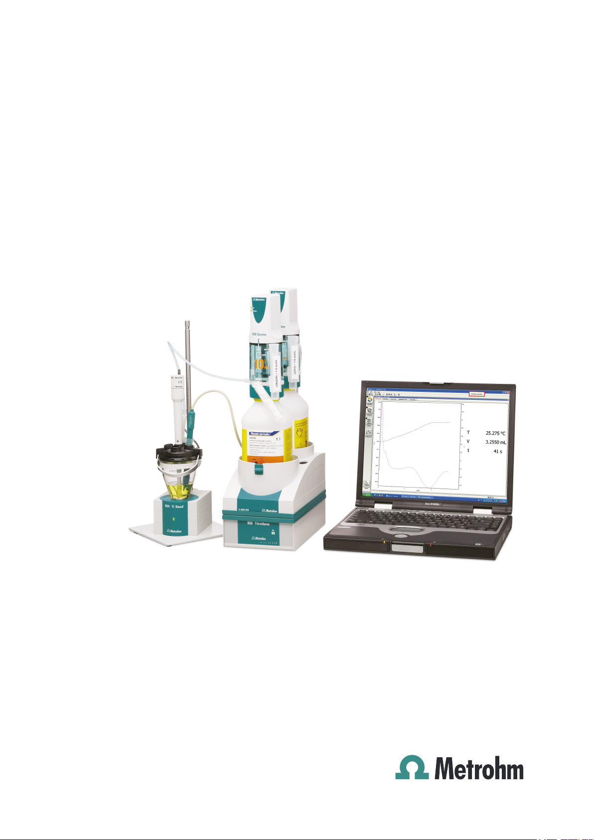
859 Titrotherm
Manual
8.859.8001EN
Page 2

Page 3

Metrohm AG
CH-9100 Herisau
Switzerland
Phone +41 71 353 85 85
Fax +41 71 353 89 01
info@metrohm.com
www.metrohm.com
859 Titrotherm
Manual
8.859.8001EN 12.2011 dm
Page 4

Teachware
Metrohm AG
CH-9100 Herisau
teachware@metrohm.com
This documentation is protected by copyright. All rights reserved.
Although all the information given in this documentation has been
checked with great care, errors cannot be entirely excluded. Should you
notice any mistakes please send us your comments using the address
given above.
Documentation in additional languages can be found on
http://products.metrohm.com under Literature/Technical documenta-
tion.
Page 5

■■■■■■■■■■■■■■■■■■■■■■
Table of contents
1 Introduction 1
1.1 The 859 Titrotherm in the Titrando system ....................... 1
1.2 Instrument description ......................................................... 3
1.2.1 Titration modes, dosing commands and other commands ....... 3
1.2.2 Intended use ........................................................................... 3
1.3 About the documentation ................................................... 4
1.3.1 Symbols and conventions ........................................................ 4
1.4 Safety instructions ................................................................ 5
1.4.1 General notes on safety ........................................................... 5
1.4.2 Electrical safety ........................................................................ 5
1.4.3 Working with liquids ................................................................ 6
1.4.4 Recycling and disposal ............................................................. 6
2 Overview of the instrument 7
Table of contents
3 Installation 9
3.1 Setting up the instrument .................................................... 9
3.1.1 Packaging ................................................................................ 9
3.1.2 Checks .................................................................................... 9
3.1.3 Location .................................................................................. 9
3.2 Connecting a computer ........................................................ 9
3.3 Connecting MSB devices .................................................... 11
3.3.1 Connecting a dosing device ................................................... 13
3.3.2 Connecting a stirrer or titration stand .................................... 13
3.3.3 Connecting a Remote Box ..................................................... 14
3.4 Connecting USB devices ..................................................... 15
3.5 Connecting a sensor ........................................................... 16
3.6 Setting up the titration cell ............................................... 17
4 Handling and maintenance 19
4.1 General notes ...................................................................... 19
4.1.1 Care ...................................................................................... 19
4.1.2 Maintenance by Metrohm Service .......................................... 19
4.2 Quality Management and validation with Metrohm ....... 20
859 Titrotherm
5 Troubleshooting 21
5.1 Problems ............................................................................. 21
■■■■■■■■
III
Page 6

Table of contents
■■■■■■■■■■■■■■■■■■■■■■
6 Appendix 22
6.1 Thermoprobes ..................................................................... 22
6.1.1 Various models ...................................................................... 22
6.1.2 Cleaning and storage ............................................................. 22
6.2 Maximum dosing and filling rate ...................................... 23
6.3 Remote interface ................................................................ 24
6.3.1 Pin assignment of the remote interface .................................. 24
7 Technical specifications 26
7.1 Measuring interface NTC 10 kOhm .................................. 26
7.2 Interfaces and connectors ................................................. 26
7.3 Mains connection ............................................................... 26
7.4 Safety specifications ........................................................... 27
7.5 Electromagnetic compatibility (EMC) ................................ 27
7.6 Ambient temperature ......................................................... 28
7.7 Reference conditions .......................................................... 28
7.8 Dimensions .......................................................................... 28
8 Warranty (guarantee) 29
9 Accessories 30
9.1 Scope of delivery 2.859.1010 ............................................ 30
9.2 Optional accessories ........................................................... 34
Index 37
■■■■■■■■
IV
859 Titrotherm
Page 7

■■■■■■■■■■■■■■■■■■■■■■
Table of figures
Figure 1 The 859 Titrotherm in the Titrando system ........................................ 2
Figure 2 Front 859 Titrotherm ......................................................................... 7
Figure 3 Rear 859 Titrotherm .......................................................................... 7
Figure 4 859 Titrotherm with titration accessories ........................................... 8
Figure 5 Connecting the computer ............................................................... 10
Figure 6 MSB connections ............................................................................ 12
Figure 7 Connecting a dosing device ............................................................. 13
Figure 8 Connecting an MSB stirrer ............................................................... 14
Figure 9 Propeller stirrer and titration stand ................................................... 14
Figure 10 Connecting a Remote Box ............................................................... 15
Figure 11 Connecting USB devices to the 859 Titrotherm ................................ 16
Figure 12 Positioning the Thermoprobe .......................................................... 18
Figure 13 Thermoprobes – two models ........................................................... 22
Figure 14 Connectors of the remote box ......................................................... 24
Figure 15 Pin assignment of the remote socket and plug ................................ 24
Table of figures
859 Titrotherm
■■■■■■■■
V
Page 8

Page 9

■■■■■■■■■■■■■■■■■■■■■■
1 Introduction
The 859 Titrotherm is a Metrohm titrator for thermometric titration. Thermometric titration can be utilized where potentiometric indication is either
not possible or possible only to a limited extent.
For the theory and application possibilities of thermometric titration, we
recommend the monograph: Thomas Smith, Practical thermometric
titrimetry, Metrohm AG, 2006 (Order No. 8.036.5003).
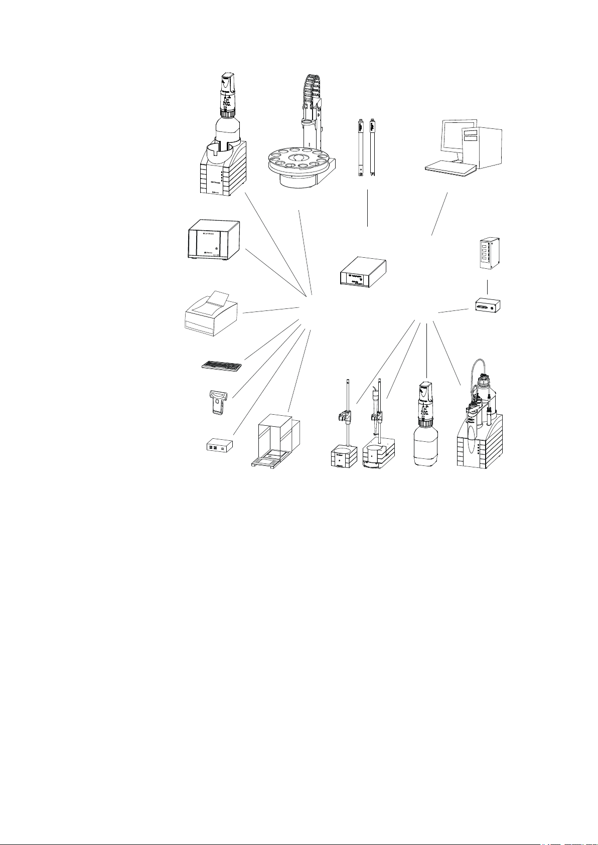
1.1 The 859 Titrotherm in the Titrando system
The 859 Titrotherm is a component of the modular Titrando system. Operation is carried out with a computer containing the software tiamo™
(starting with Version 2.2).
A Titrando system can contain numerous, various kinds of instruments.
The following figure provides an overview of the peripheral devices you
can connect to the 859 Titrotherm.
1 Introduction
859 Titrotherm
■■■■■■■■
1
Page 10
1.1 The 859 Titrotherm in the Titrando system
MSB
USB
Controller
T-Port 1 / 2
PC Keyboard
Barcode
Reader
USB Hub
Balance
USB Sample Processor
Robotic Titrosampler
Printer
Personal Computer
Relay Box
Remote Box
859 Titrotherm
Stirrer / Ti Stand Dosino Dosimat
USB/RS-232 Converter
867 pH Module
Titrando
On
■■■■■■■■■■■■■■■■■■■■■■
■■■■■■■■
2
Figure 1 The 859 Titrotherm in the Titrando system
You can request information on special applications in the "Application
Bulletins" and "Application Notes"; available free of charge via the
Metrohm representative responsible.
Updating the device software is described in the tiamo help.
859 Titrotherm
Page 11

■■■■■■■■■■■■■■■■■■■■■■
1.2 Instrument description
The 859 Titrotherm has the following characteristics:
■ Operation
Operation is carried out using the high-performance PC software
tiamo™, Version 2.2 or higher.
■ MSB connectors
Four MSB connectors (Metrohm Serial Bus) to control dosing devices
(Dosimat with exchange unit or Dosino with dosing unit), stirrer or
titration stand and Remote Boxes.
■ USB connectors
Two USB connectors, through which devices such as printers, PC keyboards, barcode readers or additional control devices (USB Sample Processor, Titrando, Dosing Interface, etc.) can be connected.
■ Measuring interface
Measuring interface with two connectors for two temperature sensors
(Thermoprobes).
1 Introduction
1.2.1 Titration modes, dosing commands and other commands
■ TET
Thermometric endpoint titration. The reagent addition takes place continuously at a constant dosing rate.
■ Dosing commands
The following commands for dosing can be selected:
– ADD (adding a predefined volume)
– PREP (rinsing the cylinder and tubings of an exchange or dosing
unit)
– EMPTY (for emptying cylinder and tubings)
– LQH (for executing complex dosing tasks)
■ Other commands
– STIR (stirrer control)
– SCAN (scanning remote signals)
– CTRL (setting remote signals)
1.2.2 Intended use
The 859 Titrotherm is designed for usage as a titrator in analytical laboratories. Its main area of application is the determination of ions in aqueous
and nonaqueous media. The 859 Titrotherm uses the method of thermometric titration.
859 Titrotherm
This instrument is suitable for processing chemicals and flammable samples. The usage of the 859 Titrotherm therefore requires that the user has
basic knowledge and experience in the handling of toxic and caustic sub-
■■■■■■■■
3
Page 12
1.3 About the documentation
stances. Knowledge with respect to the application of the fire prevention
measures prescribed for laboratories is also mandatory.
1.3 About the documentation
Caution
Please read through this documentation carefully before putting the
instrument into operation. The documentation contains information
and warnings which the user must follow in order to ensure safe operation of the instrument.
1.3.1 Symbols and conventions
The following symbols and formatting may appear in this documentation:
Cross-reference to figure legend
The first number refers to the figure number, the second to the instrument part in the figure.
■■■■■■■■■■■■■■■■■■■■■■
Instruction step
Carry out these steps in the sequence shown.
Method Dialog text, parameter in the software
File ▶ New
[Next] Button or key
Menu or menu item
Warning
This symbol draws attention to a possible life hazard
or risk of injury.
Warning
This symbol draws attention to a possible hazard due
to electrical current.
Warning
This symbol draws attention to a possible hazard due
to heat or hot instrument parts.
Warning
This symbol draws attention to a possible biological
hazard.
■■■■■■■■
4
859 Titrotherm
Page 13
■■■■■■■■■■■■■■■■■■■■■■
1.4 Safety instructions
1.4.1 General notes on safety
Warning
This instrument may only be operated in accordance with the specifications in this documentation.
This instrument has left the factory in a flawless state in terms of technical
safety. To maintain this state and ensure non-hazardous operation of the
instrument, the following instructions must be observed carefully.
1 Introduction
Caution
This symbol draws attention to a possible damage of
instruments or instrument parts.
Note
This symbol marks additional information and tips.
1.4.2 Electrical safety
The electrical safety when working with the instrument is ensured as part
of the international standard IEC 61010.
Only personnel qualified by Metrohm are authorized to carry out service
work on electronic components.
Never open the housing of the instrument. The instrument could be
damaged by this. There is also a risk of serious injury if live components
are touched.
There are no parts inside the housing which can be serviced or replaced
by the user.
Warning
Warning
859 Titrotherm
■■■■■■■■
5
Page 14
1.4 Safety instructions
■■■■■■■■■■■■■■■■■■■■■■
Mains voltage
Warning
An incorrect mains voltage can damage the instrument.
Only operate this instrument with a mains voltage specified for it (see
rear panel of the instrument).
Protection against electrostatic charges
Warning
Electronic components are sensitive to electrostatic charges and can be
destroyed by discharges.
Always pull the mains cable out of the mains connection socket before
connecting or disconnecting electrical appliances on the rear panel of
the instrument.
1.4.3 Working with liquids
Caution
Periodically check all system connections for leaks. Observe the relevant
regulations in respect to working with flammable and/or toxic fluids
and their disposal.
1.4.4 Recycling and disposal
This product is covered by European Directive 2002/96/EC, WEEE – Waste
from Electrical and Electronic Equipment.
The correct disposal of your old equipment will help to prevent negative
effects on the environment and public health.
More details about the disposal of your old equipment can be obtained
from your local authorities, from waste disposal companies or from your
local dealer.
■■■■■■■■
6
859 Titrotherm
Page 15

■■■■■■■■■■■■■■■■■■■■■■
1
1
2
3 4 5 6
2 Overview of the instrument
Figure 2 Front 859 Titrotherm
LED "On"
1
Lights up when the device and a computer
are connected to the mains and switched
on.
2 Overview of the instrument
Figure 3 Rear 859 Titrotherm
Measuring interface: T-Port 1 and 2
1
For connecting two Thermoprobes.
Controller connector (Controller)
3
Connector for a PC with installed PC software. Mini DIN, 9-pin.
Mains connection socket
5
859 Titrotherm
USB connector (USB 1 and USB 2)
2
USB ports (type A) for connecting printer,
keyboard, barcode reader, additional Titrandos, USB Sample Processor, etc.
MSB connector (MSB 1 to MSB 4)
4
Metrohm Serial Bus. For connecting external
dosing devices, stirrers or Remote Boxes.
Mini DIN, 9-pin.
Type plate
6
Contains specifications concerning mains
voltage, instrument type and serial number.
■■■■■■■■
7
Page 16

■■■■■■■■■■■■■■■■■■■■■■
1
2
3
4
5
6
Figure 4 859 Titrotherm with titration accessories
800 Dosino
1
Dosing drive for the titrant.
Bottle (6.1608.XXX)
3
Stacking frame (6.2065.000)
5
Dosing unit (6.3032.XXX)
2
With cylinder sizes 2, 5, 10, 20, 50 mL.
Bottle holder for Dosinos (6.2061.010)
4
859 Titrotherm
6
■■■■■■■■
8
859 Titrotherm
Page 17

■■■■■■■■■■■■■■■■■■■■■■
3 Installation
3.1 Setting up the instrument
3.1.1 Packaging
The instrument is supplied in highly protective special packaging together
with the separately packed accessories. Keep this packaging, as only this
ensures safe transportation of the instrument.
3.1.2 Checks
Immediately after receipt, check whether the shipment has arrived complete and without damage by comparing it with the delivery note.
3.1.3 Location
The instrument has been developed for operation indoors and may not be
used in explosive environments.
3 Installation
Place the instrument in a location of the laboratory which is suitable for
operation, free of vibrations, protected from corrosive atmosphere, and
contamination by chemicals.
The instrument should be protected against excessive temperature fluctuations and direct sunlight.
3.2 Connecting a computer
The 859 Titrotherm requires a USB connection to a computer in order to
be able to be controlled by a PC software. Using a 6.2151.000 controller
cable, the instrument can be connected directly, either to a USB socket on
a computer, to a connected USB hub or to a different Metrohm control
device.
You need administrator rights for the installation of the driver and software on your PC.
Cable connection and driver installation
A driver installation is required in order to ensure that the 859 Titrotherm
is recognized by the PC software. To accomplish this, you must comply
with the procedures specified. The following steps are necessary:
1
Install the software
■ Insert the PC software installation CD and carry out the installa-
tion program directions.
859 Titrotherm
■■■■■■■■
9
Page 18

3.2 Connecting a computer
6.2151.000
■■■■■■■■■■■■■■■■■■■■■■
■ Exit the program if you have started it after the installation.
2
Establish the cable connections
■ Connect all peripheral devices to the instrument .
■ Connect the 859 Titrotherm to the mains supply if you have not
already done this.
The "On" LED on the 859 Titrotherm is not yet illuminated!
■ Connect the instrument to a USB connector (Type A) of your com-
puter (see manual of your computer). The 6.2151.000 cable is
used for this purpose.
Figure 5 Connecting the computer
The instrument is recognized. The driver installation is carried out differently, depending on the version of the Windows operating system
used.
■ Either the required driver is installed automatically, or an installa-
tion wizard is started.
Follow the instructions of the installation wizard.
3
The "On" LED on the 859 Titrotherm lights up when the driver installation has been exited and the instrument is ready for operation.
If problems should occur during installation, contact your company's IT
supporter.
Note
The plug on the instrument end of the 6.2151.000 controller cable is
protected against accidental disconnection by means of a pull-out protection feature. If you wish to pull out the plug, you will first need to
pull back the outer plug sleeve marked with arrows.
■■■■■■■■
10
859 Titrotherm
Page 19

■■■■■■■■■■■■■■■■■■■■■■
Registering and configuring the instrument in the PC software
The instrument must be registered in the configuration of your PC software. Once that has been done, you can then configure it according to
your requirements. Proceed as follows:
1
Set up the instrument
■ Start the PC software.
The instrument is automatically recognized. The configuration dialog for the instrument is displayed.
■ Make configuration settings for the instrument and its connec-
tors.
More detailed information concerning the configuration of the
instrument can be found in the documentation for the respective PC
software.
3.3 Connecting MSB devices
3 Installation
In order to connect MSB devices, e.g. stirrers or dosing devices, Metrohm
instruments are equipped with up to four connectors on what is referred
to as the Metrohm Serial Bus (MSB). Various kinds of peripheral devices
can be connected in sequence (in series, as a «daisy chain») at a single
MSB connector (8-pin Mini DIN socket) and controlled simultaneously by
the respective control device. In addition to the connection cable, stirrers
and the Remote Box are each equipped with their own MSB socket for
this purpose.
The following figure provides an overview of the devices that can be connected to an MSB socket, along with a number of different cabling variations.
859 Titrotherm
■■■■■■■■
11
Page 20

3.3 Connecting MSB devices
MSB
Stirrer / Ti Stand
Dosino
Remote Box
Dosino
Dosino
Relay Box
Ti Stand / Stirrer
■■■■■■■■■■■■■■■■■■■■■■
Figure 6 MSB connections
The question of which peripheral devices are supported depends on the
control device.
Note
When connecting MSB devices together, the following must be
observed:
■ Only one device of the same type can be used at a single MSB con-
nector at one time.
■ Type 700 Dosino dosing devices cannot be connected together with
other MSB instruments on a shared connector. These dosing devices
must be connected separately.
Caution
Exit the control software before you plug MSB instruments in. When
the control device is switched on, it automatically recognizes which
instrument is connected at which MSB connector. The control software
enters the connected MSB devices into the system configuration (device
manager).
MSB connections can be extended with the 6.2151.010 cable. The maximum connection length permitted is 15 m.
12
■■■■■■■■
859 Titrotherm
Page 21

■■■■■■■■■■■■■■■■■■■■■■
3.3.1 Connecting a dosing device
Four dosing devices can be connected to the instrument (MSB 1 to MSB
4).
The types of dosing devices that are supported are:
■ 700 Dosino
■ 800 Dosino
■ 805 Dosimat
Proceed as follows:
1
Connect the dosing device
■ Exit the control software.
■ Connect the connection cable to one of the sockets marked with
MSB on the rear of the 859 Titrotherm.
■ Start the control software.
3 Installation
Figure 7 Connecting a dosing device
3.3.2 Connecting a stirrer or titration stand
You can use the magnetic stirrers 801 Stirrer or 803 Ti Stand (stirring
"from below") or the 804 Ti Stand with a propeller stirrer 802 Stirrer (stirring "from above").
Connect a stirrer or a titration stand as follows:
1
Connect the stirrer or titration stand
■ Exit the control software.
■ Connect the connection cable of the magnetic stirrer or of the
titration stand to one of the sockets marked with MSB on the
rear of the 859 Titrotherm.
859 Titrotherm
■■■■■■■■
13
Page 22

3.3 Connecting MSB devices
■■■■■■■■■■■■■■■■■■■■■■
■ If desired, connect the propeller stirrer to the stirrer socket (with
stirrer symbol) of the titration stand.
■ Start the control software.
Figure 8 Connecting an MSB stirrer
Figure 9 Propeller stirrer and titration stand
3.3.3 Connecting a Remote Box
Instruments that are controlled via remote lines and/or which send control
signals via remote lines can be connected using the 6.2148.010 Remote
Box. In addition to Metrohm, other instrument manufacturers also use
similar connectors that make it possible to connect different instruments
together. These interfaces are also frequently given the designations "TTL
Logic", "I/O Control" or "Relay Control" and generally have a signal level
of 5 volts.
Control signals are understood to be electrical line statuses or electrical
pulses (> 200 ms) which display the operating status of an instrument or
which trigger or report an event. Sequences on a variety of instruments
can thus be coordinated in a single complex automation system. No
exchange of data is possible, however.
Proceed as follows:
1
Connect the Remote Box
■ Exit the control software.
■■■■■■■■
14
859 Titrotherm
Page 23

■■■■■■■■■■■■■■■■■■■■■■
3 Installation
■ Connect the Remote Box connection cable to one of the sockets
marked with MSB on the rear of the control device.
■ Start the control software.
Figure 10 Connecting a Remote Box
You can, for example, connect an 849 Level Control (fill level monitoring
in a canister) or a 731 Relay Box (switch box for 230/110 volt alternating
current sockets and low-voltage direct current outlets). The Remote Box
also has an MSB socket at which a further MSB device, e.g. a dosing
device or a stirrer, can be connected.
You will find precise information concerning the pin assignment of the
interface on the Remote Box in the Appendix (see Chapter 6.3, page
24).
3.4 Connecting USB devices
Additional Metrohm devices, such as USB Sample Processors, Dosing
Interfaces, Titrandos, etc. can be connected to the 859 Titrotherm.
Proceed as follows:
Connect one 6.2151.000 connecting cable with one end (8-pin Mini
1
DIN plug) to the Controller connector of the Metrohm device.
Connect the other end of the connecting cable to the connector
2
USB1 or USB2 of the 859 Titrotherm.
859 Titrotherm
■■■■■■■■
15
Page 24

3.5 Connecting a sensor
6.2151.000
Figure 11 Connecting USB devices to the 859 Titrotherm
This way, several Metrohm devices can be connected with one another
and be controlled simultaneously from one PC software.
3.5 Connecting a sensor
Connect the Thermoprobe as follows:
■■■■■■■■■■■■■■■■■■■■■■
Plug the Thermoprobe plug into the T-Port 1 or T-Port 2 socket of
1
the 859 Titrotherm.
Note the orientation of the plug.
Connecting a Thermoprobe
In order to disconnect the sensor, the outer plug sleeve on the plug must
first be retracted.
Note
■■■■■■■■
16
Never use the cable to pull out the sensor!
859 Titrotherm
Page 25

■■■■■■■■■■■■■■■■■■■■■■
1
6
7
8
2
3
4
5
3.6 Setting up the titration cell
Install the titration cell in accordance with the following figure:
3 Installation
Propeller stirrer (802 Stirrer)
1
Connect the stirrer to the stirrer connector
on the rear of the titration stand.
SGJ sleeve (6.1236.050)
3
SGJ 14/12 mm Material: PE.
Stirring propeller (6.1909.010)
5
L= 96 mm, Material: PP.
Antidiffusion tip M6 (6.1543.200)
7
L=151 mm, Material: ETFE/FEP.
859 Titrotherm
Sensor Thermoprobe (6.9011.020 or
2
6.9011.040)
Connect the sensor at T-Port 1 (or T-Port 2)
to the rear side of the 859 Titrotherm.
SGJ intermediate cone (6.2727.010)
4
For the 802 Stirrer.
FEP tubing (6.1805.100)
6
Connect the tubing (40 cm) to Port 1 on the
dosing unit.
Link stopper (6.1446.030)
8
Material: ETFE.
■■■■■■■■
17
Page 26

3.6 Setting up the titration cell
1 mm 1 mm
■■■■■■■■■■■■■■■■■■■■■■
Figure 12 Positioning the Thermoprobe
The sensor should be installed in accordance with the above figure. A high
stirring rate is very important. Please ensure that there is a sufficient
amount of liquid in the vessel so that the sensor is immersed at least 1 cm,
even when the solution is being stirred at high speed. A visible stirring funnel must result.
■■■■■■■■
18
859 Titrotherm
Page 27

■■■■■■■■■■■■■■■■■■■■■■
4 Handling and maintenance
4.1 General notes
4.1.1 Care
The 859 Titrotherm requires appropriate care. Excess contamination of the
instrument may result in functional disruptions and a reduction in the lifetime of the sturdy mechanics and electronics.
Spilled chemicals and solvents should be removed immediately. Above all,
the plug connections on the rear of the instrument (in particular the mains
connection socket) should be protected from contamination.
Caution
Although this is extensively prevented by design measures, the mains
plug should be unplugged immediately if aggressive media has penetrated the inside of the instrument, so as to avoid serious damage to the
instrument electronics. In such cases, the Metrohm Service must be
informed.
4 Handling and maintenance
4.1.2 Maintenance by Metrohm Service
Maintenance of the 859 Titrotherm is best carried out as part of an annual
service performed by specialist personnel of the Metrohm company. If
working frequently with caustic and corrosive chemicals, a shorter maintenance interval could be necessary.
The Metrohm service department offers every form of technical advice for
maintenance and service of all Metrohm instruments.
859 Titrotherm
■■■■■■■■
19
Page 28

4.2 Quality Management and validation with Metrohm
■■■■■■■■■■■■■■■■■■■■■■
4.2 Quality Management and validation with Metrohm
Quality Management
Metrohm offers you comprehensive support in implementing quality management measures for instruments and software. Further information on
this can be found in the brochure «Quality Management with
Metrohm» available from your local Metrohm agent.
Validation
Please contact your local Metrohm agent for support in validating instruments and software. Here you can also obtain validation documentation
to provide help for carrying out the Installation Qualification (IQ) and
the Operational Qualification (OQ). IQ and OQ are also offered as a
service by the Metrohm agents. In addition, various application bulletins
are also available on the subject, which also contain Standard Operat-
ing Procedures (SOP) for testing analytical measuring instruments for
reproducibility and correctness.
Maintenance
Electronic and mechanical functional groups in Metrohm instruments can
and should be checked as part of regular maintenance by specialist personnel from Metrohm. Please ask your local Metrohm agent regarding the
precise terms and conditions involved in concluding a corresponding
maintenance agreement.
Note
You can find information on the subjects of quality management, validation and maintenance as well as an overview of the documents currently available at www.metrohm.com/com/ under Support.
■■■■■■■■
20
859 Titrotherm
Page 29

■■■■■■■■■■■■■■■■■■■■■■
5 Troubleshooting
5.1 Problems
Problem Cause Remedy
5 Troubleshooting
LED "On" is not illuminated although
the instrument is
connected to the
mains.
LED "Status" is
flashing fast.
The computer has not been
switched on yet or the
plugs are not correctly
plugged in.
The data of the dosing unit
cannot be read because
the data chip has been
damaged mechanically or
by chemicals.
The dosing drive is overloaded because the piston or
the valve disc is jammed.
Check the plug connections and switch on the
computer.
Have the data chip replaced by the Metrohm
Service. Until the data chip is being replaced
you can remove the data chip yourself in order
to be able to still use the dosing unit. The cylinder volume is automatically recognized nevertheless, but no data can be read from the
dosing unit or be saved on it anymore.
Exit tiamo™ and then restart it. The dosing
device will be initialized at this time. If the
error is not rectified by these actions, attempt
to remove the dosing drive.
If this is not possible, proceed as follows:
1. Exit tiamo™.
2. Press the locking button of the dosing unit
and remove the distributor. Turn it upside
down in its entirety.
3. Start tiamo™ and initiate 'Filling' in the
manual control. If the rotation of the stopcock is clearly audible, then the dosing
unit, with Dosino attached, can be reattached to the distributor.
4. Place the dosing unit with Dosino attached
upright on the distributor, align marking rib
to marking rib, and rotate the dosing unit
to the left until the spring clip snaps audibly
into place. Now you should be able to
remove the Dosino from the dosing unit.
859 Titrotherm
■■■■■■■■
21
Page 30

6.1 Thermoprobes
6.9011.020 6.9011.040
6 Appendix
6.1 Thermoprobes
6.1.1 Various models
The sensors for the 859 Titrotherm are called Thermoprobes. A Thermoprobe is a temperature sensor that is based on semiconductor technology
(thermistor). It has a short response time of 0.3 s and a high resolution of
10–5 K. This enables the precise recording of even the smallest of temperature changes that occur during a titration.
In contrast to potentiometric electrodes, Thermoprobes need not be calibrated!
■■■■■■■■■■■■■■■■■■■■■■
Figure 13 Thermoprobes – two models
Thermoprobe with glass shaft
(6.9011.020)
For titrations in aqueous and nonaqueous
media. Not HF-resistant.
6.1.2 Cleaning and storage
The sensor can be cleaned by rinsing or brief immersion in a suitable solvent. Immerse all openings in the case of the 6.9011.020.
The sensor shaft can be carefully cleaned with a cloth.
■■■■■■■■
22
Thermoprobe with shaft made of PP
(6.9011.040)
For titrations in aqueous media. HF-resistant.
Can also be used in acidic solutions containing fluoride.
859 Titrotherm
Page 31

■■■■■■■■■■■■■■■■■■■■■■
Warning
The temperature sensor is very sensitive and can be considerably damaged by contact with fingers or objects.
Warning
The PTFE protective sleeve of the 6.9011.020 cannot and must not be
dismantled.
The sensor must always be stored in a dry place. After each sample series,
rinse the sensor with water or other cleaning solutions.
6.2 Maximum dosing and filling rate
The maximum dosing rate and maximum filling rate for the dosing unit
depend on the cylinder volume:
6 Appendix
Cylinder volume Maximum rate
2 mL 6.67 mL/min
5 mL 16.67 mL/min
10 mL 33.33 mL/min
20 mL 66.67 mL/min
50 mL 166.00 mL/min
Independent of the cylinder volume, values ranging from 0.01 to 166.00
mL/min can always be entered. When the function is carried out the rate
will be, if necessary, decreased automatically to the highest possible value.
859 Titrotherm
■■■■■■■■
23
Page 32

6.3 Remote interface
1
2
3
13
1
14
25
1
13
14
25
+5 V
t
p
6.3 Remote interface
The 6.2148.010 remote box allows devices to be controlled which cannot
be connected directly to the MSB interface of the 859 Titrotherm.
Figure 14 Connectors of the remote box
■■■■■■■■■■■■■■■■■■■■■■
Cable
1
For connecting the 859 Titrotherm.
MSB connector
2
Metrohm Serial Bus. For connecting external
dosing devices or stirrers.
Remote connector
3
For connecting devices with a remote interface.
6.3.1 Pin assignment of the remote interface
Figure 15 Pin assignment of the remote socket and plug
The above presentation of the pin assignment of a Metrohm remote interface applies not only for the remote box, but also for all Metrohm devices
with 25-pin D-Sub remote connection.
Inputs
approx. 50 kΩ Pull-up
tp >20 ms
active = low, inactive = high
24
■■■■■■■■
859 Titrotherm
Page 33

■■■■■■■■■■■■■■■■■■■■■■
t
p
6 Appendix
The input lines can be scanned with the SCAN command.
Outputs
Open Collector
tp >200 ms
active = low, inactive = high
IC = 20 mA, V
CEO
= 40 V
+5 V: maximum load = 20 mA
The output lines can be set with the CONTROL command.
Table 1 Inputs and outputs of the remote interface
Assigment Pin No. Assigment Pin No.
Input 0 21 Output 0 5
Input 1 9 Output 1 18
Input 2 22 Output 2 4
Input 3 10 Output 3 17
Input 4 23 Output 4 3
Input 5 11 Output 5 16
Input 6 24 Output 6 1
Input 7 12 Output 7 2
0 volts / GND 14 Output 8 6
859 Titrotherm
+5 volts 15 Output 9 7
0 volts / GND 25 Output 10 8
Output 11 13
Output 12 19
Output 13 20
■■■■■■■■
25
Page 34

7.1 Measuring interface NTC 10 kOhm
7 Technical specifications
7.1 Measuring interface NTC 10 kOhm
■■■■■■■■■■■■■■■■■■■■■■
Measuring range
Resolution
Measuring cycle
Measurement
imprecision
–10…+50 °C
0.00001 °C
20 ms at 50 Hz mains frequency
±0.1 °C
7.2 Interfaces and connectors
Controller connector
MSB connectors
MSB1…MSB4
USB connectors
1/2
USB Upstream port (9-pin Mini DIN socket) for connecting a computer
for controlling the instrument.
Four 9-pin Mini DIN sockets for connecting dosing devices (Dosino/
Dosimat), stirrers, etc.
Two USB Downstream Ports (Type A sockets), each 500 mA, for connecting Metrohm instruments or USB peripheral devices of other manufacturers.
7.3 Mains connection
Voltage
Frequency
Power consumption
Fuse
100…240 V (±10 %)
50…60 Hz
maximum 45 W
Electronic overload protection
■■■■■■■■
26
859 Titrotherm
Page 35

■■■■■■■■■■■■■■■■■■■■■■
7.4 Safety specifications
This instrument fulfills the following electrical safety requirements:
CE designation in accordance with the EU directives:
■ 2006/95/EC (Low Voltage Directive, LVD)
■ 2004/108/EC (EMC Directive, EMC)
Federal Inspectorate for Heavy Current Installations ESTI (Accreditation
Number SCESp 033)
■ Safety mark for certification type 2 in accordance with NEV (type
testing with market monitoring, EMC conformity)
7 Technical specifications
Design and testing
According to EN/IEC 61010-1, UL 61010-1, CSA-C22.2 No. 61010-1,
degree of protection IP20, protection class I.
Safety instructions
This document contains safety instructions which have to be followed
by the user in order to ensure safe operation of the instrument.
7.5 Electromagnetic compatibility (EMC)
Emission
Immunity
Standards fulfilled:
■ EN/IEC 61326-1
■ EN/IEC 61000-6-3
■ EN 55022 / CISPR 22
Standards fulfilled:
■ EN/IEC 61326-1
■ EN/IEC 61000-6-2
■ EN/IEC 61000-4-2
■ EN/IEC 61000-4-3
■ EN/IEC 61000-4-4
■ EN/IEC 61000-4-5
■ EN/IEC 61000-4-6
■ EN/IEC 61000-4-11
■ EN/IEC 61000-4-14
859 Titrotherm
■■■■■■■■
27
Page 36

7.6 Ambient temperature
7.6 Ambient temperature
■■■■■■■■■■■■■■■■■■■■■■
Nominal function
range
Storage
Transport
+5…+45 °C
–20…+60 °C
–40…+60 °C
7.7 Reference conditions
Ambient temperature
Relative humidity
Instrument status
Validity of the
data
+25 °C (±3 °C)
≤ 60 %
Instrument in operation at least 30 min
After adjustment
7.8 Dimensions
Width
Height
142 mm
64 mm
Depth
Weight
Material
Housing
230 mm
2.0 kg
Metal housing, surface-treated
■■■■■■■■
28
859 Titrotherm
Page 37

■■■■■■■■■■■■■■■■■■■■■■
8 Warranty (guarantee)
Metrohm guarantees that the deliveries and services it provides are free
from material, design or manufacturing errors. The warranty period is 36
months from the day of delivery; for day and night operation it is 18
months. The warranty remains valid on condition that the service is provided by an authorized Metrohm service organization.
Glass breakage is excluded from the warranty for electrodes and other
glassware. The warranty for the accuracy corresponds to the technical
specifications given in this manual. For components from third parties that
make up a considerable part of our instrument, the manufacturer's warranty provisions apply. Warranty claims cannot be pursued if the Customer
has not complied with the obligations to make payment on time.
During the warranty period Metrohm undertakes, at its own choice, to
either repair at its own premises, free of charge, any instruments that can
be shown to be faulty or to replace them. Transport costs are to the Customer's account.
8 Warranty (guarantee)
Faults arising from circumstances that are not the responsibility of
Metrohm, such as improper storage or improper use, etc. are expressly
excluded from the warranty.
859 Titrotherm
■■■■■■■■
29
Page 38

9.1 Scope of delivery 2.859.1010
9 Accessories
Note
Subject to change without notice.
9.1 Scope of delivery 2.859.1010
Qty. Order no. Description
1 1.800.0010 800 Dosino
1 1.802.0010 802 Stirrer
■■■■■■■■■■■■■■■■■■■■■■
1 1.804.0010 804 Ti Stand
1 1.859.0010 859 Titrotherm
1 6.1414.010 Titration vessel lid with 5 openings
Material: PPS
SGJ size: A-14/15
1 6.1415.210 Titration vessel / 10-90 mL
Material: Clear glass
Height (mm): 80
Outer diameter (mm): 78
Volume (mL): 10 ... 90
■■■■■■■■
30
859 Titrotherm
Page 39

■■■■■■■■■■■■■■■■■■■■■■
Qty. Order no. Description
1 6.1546.030 Piston tongs
For the PTFE pistons of the dosing unit.
1 6.1909.010 Stirring propeller / 96 mm
Stirring propeller, fitting length from lower edge of the ground joint:
96 mm. For usage in beakers with 722, 802 propeller stirrer.
Material: PP
9 Accessories
1 6.2013.010 Clamping ring
For support rods with a diameter of 10 mm.
Material: Metal
Width (mm): 20
Height (mm): 16
1 6.2026.010 Stand plate with support rod
Complete, with support rod, total length 42 cm. For when using the
magnetic swivel stirrer 649, 728 alone (without Dosimat).
Width (mm): 166
Height (mm): 420
Outer diameter (mm): 10
Length (m): 166
859 Titrotherm
■■■■■■■■
31
Page 40

9.1 Scope of delivery 2.859.1010
Qty. Order no. Description
1 6.2036.000 Mounting ring for titration vessels
Material: Plastic
1 6.2151.000 Cable USB A – Mini DIN 8-pin
Controller cable.
Length (m): 1.8
1 6.2621.070 Hexagon key 5 mm
Length (mm): 80
■■■■■■■■■■■■■■■■■■■■■■
1 6.2621.130 Hexagon key 2 mm
2 mm.
■■■■■■■■
32
859 Titrotherm
Page 41

■■■■■■■■■■■■■■■■■■■■■■
Qty. Order no. Description
1 6.2727.010 SGJ intermediate cone
For reference and auxiliary electrodes in the measuring and titration
vessel with the lid 6.1414.010.
Material: PP
Outer diameter (mm): 18
Inner diameter (mm): 12
Length (mm): 25
1 6.3032.210 Dosing unit 10 mL
Dosing unit with integrated data chip with 10 mL glass cylinder and
light protection, mountable to a reagent bottle with ISO/DIN GL 45
glass thread. FEP tubing connection, antidiffusion buret tip.
Volume (mL): 10
1 6.6056.231 tiamo™ 2.3 Light CD: 1 license
9 Accessories
tiamo™ 2.3 light PC program for controlling a titration system. Up to
two devices can be connected, graphical method editor with numerous templates, layout manager for modifying the screen surface, professional database with reevaluation, powerful report generator, no
parallel titration, no data export, 1 license, dialog languages German,
English.
1 6.9011.020 Thermoprobe for 859 Titrotherm
Temperature sensor made of glass for thermometric titration with
the 859 Titrotherm for aqueous or nonaqueous solutions.
Shaft material: Glass
Shaft material addition: PTFE
Measuring range: 0 ... 60
Measuring unit: °C
Shaft diameter top (mm): 12
Shaft diameter bottom (mm): 12
Shaft length to head (mm): 125
Minimum immersion depth
(mm):
Electrode plug-in head: Fixed cable (l = 1.2 m) with 7-pin
1 6.2122.0x0 Mains cable with C13 line socket
IEC-60320-C13
20
Lemo plug
859 Titrotherm
Cable plug according to customer requirements.
Switzerland: Type SEV 12
6.2122.020
Germany, …: Type CEE(7), VII
■■■■■■■■
33
Page 42

9.2 Optional accessories
Qty. Order no. Description
6.2122.040
USA, …: Type NEMA/ASA
6.2122.070
1 8.859.8001DE 859 Titrotherm Manual
9.2 Optional accessories
Qty. Order no. Description
1 6.1450.210 PFA titration vessel / 10 to 90 mL
For ultratrace analysis and for solutions containing fluoride.
Material: PFA
Height (mm): 88
Outer diameter (mm): 77
Volume (mL): 10 ... 90
■■■■■■■■■■■■■■■■■■■■■■
1 6.1543.210 Stopper with three buret tips
Stopper with three buret tips for connecting three M6 tubes.
SGJ size: SGJ 14
1 6.1575.150 Dosing unit complete / 5 mL
For dosing solvents or solutions with Dosinos.
Material: ETFE
Note, Material: Cylinder
Material 2: PVDF
Note, Material 2: Housing
Volume (mL): 5
■■■■■■■■
34
859 Titrotherm
Page 43

■■■■■■■■■■■■■■■■■■■■■■
Qty. Order no. Description
1 6.2061.010 Bottle holder for Dosinos
Bottle holder for up to two Dosinos, mounted on 1 L reagent bottles.
1 6.2065.000 Stacking frame for 846 Dosing Interface,
856 Conductivity Module, 867 pH Module
For holding the Reagent Organizer on the Dosing Interface.
1 6.3032.120 Dosing unit 2 mL
Dosing unit with integrated data chip with 2 mL glass cylinder and
light protection, mountable to a reagent bottle with ISO/DIN GL 45
glass thread. FEP tubing connection, antidiffusion buret tip.
Volume (mL): 2
9 Accessories
1 6.3032.150 Dosing unit 5 mL
Dosing unit with integrated data chip with 5 mL glass cylinder and
light protection, mountable to a reagent bottle with ISO/DIN GL 45
glass thread. FEP tubing connection, antidiffusion buret tip.
Volume (mL): 5
1 6.3032.220 Dosing unit 20 mL
Dosing unit with integrated data chip with 20 mL glass cylinder and
light protection, mountable to a reagent bottle with ISO/DIN GL 45
glass thread. FEP tubing connection, antidiffusion buret tip.
Volume (mL): 20
1 6.3032.250 Dosing unit 50 mL
Dosing unit with integrated data chip with 50 mL glass cylinder and
light protection, mountable to a reagent bottle with ISO/DIN GL 45
glass thread. FEP tubing connection, antidiffusion buret tip.
Volume (mL): 50
859 Titrotherm
■■■■■■■■
35
Page 44

9.2 Optional accessories
Qty. Order no. Description
1 6.9011.040 HF Thermoprobe for 859 Titrotherm
Thermoprobe for the 859 Titrotherm for titration in media containing
HF.
Shaft material: PP
Shaft material addition: Epoxy
Measuring range: 0 ... 60
Measuring unit: °C
Shaft diameter top (mm): 12
Shaft diameter bottom (mm): 12
Shaft length to head (mm): 125
Minimum immersion depth
(mm):
Electrode plug-in head: Fixed cable (l = 1.2 m) with 7-pin
15
Lemo plug
■■■■■■■■■■■■■■■■■■■■■■
■■■■■■■■
36
859 Titrotherm
Page 45

■■■■■■■■■■■■■■■■■■■■■■
Index
Index
Numbers/Symbols
700 Dosino .............................. 13
800 Dosino .............................. 13
801 Stirrer ................................ 13
803 Ti Stand ............................. 13
804 Ti Stand ............................. 13
805 Dosimat ............................ 13
A
Antidiffusion tip ........................ 17
B
Bottle holder .............................. 8
C
Cleaning ................................... 22
Computer
Connect ............................... 9
Connect
Computer ............................. 9
Dosing device ..................... 13
MSB devices ....................... 11
Remote Box ........................ 14
Stirrer or titration stand ...... 13
Connector
Controller ............................. 7
MSB ................................. 3, 7
USB .................................. 3, 7
Controller cable 6.2151.000 ....... 9
Controller connector ................ 26
D
Data chip ................................. 21
Device software
Update ................................. 2
Dosing command ....................... 3
Dosing commands ...................... 3
Dosing device
Connect ............................. 13
Dosing rate
Maximum ........................... 23
Dosing unit ........................... 8, 21
Dosino ....................................... 8
Driver
Install ................................... 9
E
Electrostatic charge .................... 6
F
Filling rate
Maximum ........................... 23
G
Glass shaft ................................ 22
GLP .......................................... 20
Guarantee ................................ 29
H
HF-resistant .............................. 22
I
Installation
Driver ................................... 9
Instrument description ................ 3
Instrument type .......................... 7
Intended use .............................. 3
Intermediate cone .................... 17
L
LED
On ................................. 7, 21
Status ................................. 21
Link stopper ............................. 17
M
Magnetic stirrer
Connect ............................. 13
Mains connection ....................... 7
Mains voltage ............................. 6
Maintenance ............................ 19
Measuring interface .......... 3, 7, 26
Measuring range ...................... 26
Metrohm Serial Bus MSB, see also
"MSB" ...................................... 11
MSB
Connect devices ................. 11
MSB connector ..................... 3, 26
O
Overview of the instrument ........ 7
P
Pins .......................................... 24
Piston jammed ......................... 21
Propeller stirrer ......................... 17
Q
Quality Management ................ 20
R
Remote
Input .................................. 24
Interface ............................. 24
Output ............................... 25
Remote box
Pin assignment ................... 24
Remote Box
Connect ............................. 14
S
Safety instructions ...................... 5
Sensor ...................................... 17
Connect ............................. 16
Serial number ............................. 7
Service ....................................... 5
Service Agreement ................... 20
SGJ sleeve ................................ 17
Stacking frame ........................... 8
Stirrer ....................................... 17
Connect ............................. 13
Stirring propeller ....................... 17
Storage .................................... 22
T
TET ............................................. 3
Thermoprobe 16, 17, 18, 22
tiamo ......................................... 3
Titration cell
Set up ................................ 17
Titration mode ........................... 3
TET ....................................... 3
Titration stand .......................... 13
Connect ............................. 13
U
Update
Device software .................... 2
USB connector ............... 3, 15, 26
V
Validation ................................. 20
W
Warranty .................................. 29
859 Titrotherm
■■■■■■■■
37
 Loading...