

Page 1
845 Eluent Synthesizer
Handbuch
8.845.8001EN
Page 2

Page 3

Metrohm AG
CH-9100 Herisau
Switzerland
Phone +41 71 353 85 85
Fax +41 71 353 89 01
info@metrohm.com
www.metrohm.com
845 Eluent Synthesizer
8.845.8001EN
Handbuch
08.2008 zst
Page 4

Teachware
Metrohm AG
CH-9100 Herisau
teachware@metrohm.com
This documentation is protected by copyright. All rights reserved.
Although all the information given in this documentation has been
checked with great care, errors cannot be entirely excluded. Should you
notice any mistakes please send us your comments using the address
given above.
Documentation in additional languages can be found on
http://documents.metrohm.com.
Page 5

Contents
Table of contents
1 Introduction.................................................... 1
1.1 Instrument description ............................................................. 1
1.2 Parts and controls .................................................................... 1
1.2.1 Front of 2.845.0010 .......................................................................2
1.2.2 Front of 2.845.0020 .......................................................................3
1.2.3 Rear view .......................................................................................4
1.3 Information on the Instructions for Use .................................. 6
1.3.1 Organization ..................................................................................6
1.3.2 Notation and pictograms ..............................................................7
1.4 Safety information..................................................................... 8
1.4.1 Electrical safety..............................................................................8
1.4.2 General precautionary rules .......................................................... 8
2 Installation ..................................................... 9
2.1 Setting up the instrument ......................................................... 9
2.1.1 Packaging...................................................................................... 9
2.1.2 Check.............................................................................................9
2.1.3 Location ......................................................................................... 9
2.2 Mains connection...................................................................... 9
2.3 Connection to PC.................................................................... 10
2.4 Dosino(s)/Stirrer connections................................................ 11
2.5 Tubing connections ................................................................ 11
2.5.1 Instrument with tubing connections ............................................12
2.5.2 Connecting the drainage tubing .................................................13
2.5.3 Connections to bottle adapter ....................................................13
2.5.4 Connecting the components.......................................................13
2.6 pH Controller........................................................................... 14
2.6.1 Tubing connection for pH Controller........................................... 14
2.6.2 pH Controller cable connection ..................................................15
3 «Mix Control» software................................. 16
3.1 Introduction to the software ................................................... 16
3.1.1 The principle of «Mix Control» .....................................................16
3.1.2 Procedure after the first start of «Mix Control» ............................16
3.2 Main Window........................................................................... 16
3.2.1 Menus..........................................................................................16
3.2.2 Description of the symbols .........................................................19
3.3 Method..................................................................................... 20
3.3.1 General information about methods ...........................................20
3.3.2 Parameters ..................................................................................20
3.3.3 pH Adjustment.............................................................................21
3.3.4 Creating a method.......................................................................23
3.4 Configuration .......................................................................... 23
3.4.1 Depot ........................................................................................... 23
3.4.2 Components................................................................................25
3.4.3 System Settings........................................................................... 26
3.4.4 Report Configuration ...................................................................27
3.4.5 User Administration ..................................................................... 29
3.4.6 Rinse............................................................................................33
3.5 Extras....................................................................................... 36
3.5.1 Sign methods ..............................................................................36
845 Eluent Synthesizer / Instructions for Use 8.845.8001EM
I
Page 6

Contents
3.5.2 Audit trail...................................................................................... 37
3.5.3 Window "Report List" ................................................................... 39
3.5.4 GLP Manager .............................................................................. 41
3.5.5 Firmware Update......................................................................... 43
3.5.6 Login Service............................................................................... 44
4 Maintenance - Troubleshooting...................45
4.1 Care .........................................................................................45
4.1.1 Decommissioning .......................................................................45
4.2 Dosing units ............................................................................ 45
4.2.1 Deinstallation............................................................................... 45
4.2.2 Cleaning ...................................................................................... 46
4.2.3 Installation ...................................................................................47
4.3 Troubleshooting...................................................................... 49
5 Annex ............................................................50
5.1 Technical data......................................................................... 50
5.1.1 Interfaces..................................................................................... 50
5.1.2 Mains connection........................................................................ 50
5.1.3 Safety specifications ...................................................................50
5.1.4 Electromagnetic compatibility (EMC) .........................................50
5.1.5 Ambient temperature ..................................................................51
5.1.6 Dosing drive ................................................................................ 51
5.1.7 Dosing Unit.................................................................................. 51
5.1.8 Reference conditions .................................................................. 51
5.1.9 Dimensions ................................................................................. 51
5.2 Standard equipment ............................................................... 52
5.2.1 Standard equipment for 2.845.0010........................................... 52
5.2.2 Standard equipment for 2.845.0020........................................... 54
5.2.3 Accessories for pH adjustment (optional) .................................. 57
5.2.4 Optional accessories ..................................................................61
5.2.5 Producers of concentrates and standards ................................. 62
5.2.6 Systems for producing ultra pure water ..................................... 62
5.3 Warranty .................................................................................. 63
5.3.1 Warranty ......................................................................................63
5.3.2 Declaration of Conformity ...........................................................64
5.3.3 Quality Management Principles .................................................. 65
5.3.4 Index............................................................................................ 66
List of figures
Figure 1: Front of 2.845.0010 ....................................................................... 2
Figure 2: Front of 2.845.0020 ....................................................................... 3
Figure 3: Rear view of 845 Eluent Synthesizer ............................................. 4
Figure 4: Tubing connections..................................................................... 12
Figure 5: Dosing unit attachment ............................................................... 46
Figure 6: Connections with one Dosino ..................................................... 47
Figure 7: Connections with two Dosinos.................................................... 48
845 Eluent Synthesizer / Instructions for Use 8.845.8001EN
II
Page 7
1.1 Instrument description
1 Introduction
The 845 Eluent Synthesizer and its associated «Mix Control» software can be used for the fully automatic preparation of solutions and
mixtures such as eluents, mobile phases, buffer solutions or standards
with the required concentration and component ratios.
The 845 Eluent Synthesizer is based on the Dosino technology which
allows high-precision dosing to be carried out. Both aqueous (acidic or
basic) and organic mixtures can be prepared. The system (with an optional extension) can also be used to adjust the pH.
1.1 Instrument description
Two versions of the instrument are available :
• 2.845.0010 845 Eluent Synthesizer with one Dosino
• 2.845.0020 845 Eluent Synthesizer with two Dosinos
The 2.845.0010 Eluent Synthesizer with one Dosino can be used to mix
together three components (of which one is the main component).
The 2.845.0020 Eluent Synthesizer with two Dosinos can be used to
mix together five components (of which one is the main component).
Both versions contain a built-in magnetic stirrer The software «Mix Control» is supplied with the instrument.
The 2.702.0120 Eluent Synthesizer Package for the automatic pH adjustment is offered as an option. In addition to a 702 Titrino this also
contains an Aquatrode, a 10 mL exchange unit and a Remote Box (see
Section
The 845 Eluent Synthesizer is connected to a PC via a USB and operated with the «Mix Control» PC software provided. The operation of the
software is described in the online help and in Section
structions for Use.
5.2.3).
1.2 Parts and controls
3 of these In-
In this Section you will find the numbers and designations of the parts
and controls of the 845 Eluent Synthesizer. The numbering applies
throughout the Instructions for Use, i.e. bold numbers in the text (e.g.
3
) refer to the parts and controls illustrated here.
845 Eluent Synthesizer / Instructions for Use 8.845. 8001EN
1
Page 8
1 Introduction
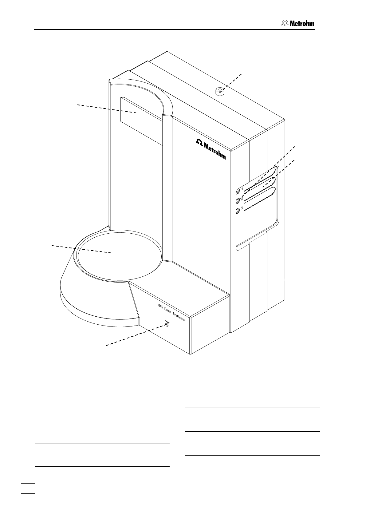
1.2.1 Front of 2.845.0010
4
3
5
6
2
1
Figure 1: Front of 2.845.0010
LED "Power"
1
Lights up green when the instrument is
switched on.
Place for eluent bottle
2
To place the eluent bottle while preparing the mixture. There is a built-in
magnetic stirrer beneath it.
Holder for bottle adapter
3
Holder for bottle adapter
21.
Dosino 1 outlet
4
Outlet for the components from Dosino
1.
Connections for components
5
Connections for components 1 - 3.
Recesses for magnetic labels
6
For identifying components 1 - 3.
2
845 Eluent Synthesizer / Instructions for Use 8.845. 8001EN
Page 9
1.2 Parts and controls
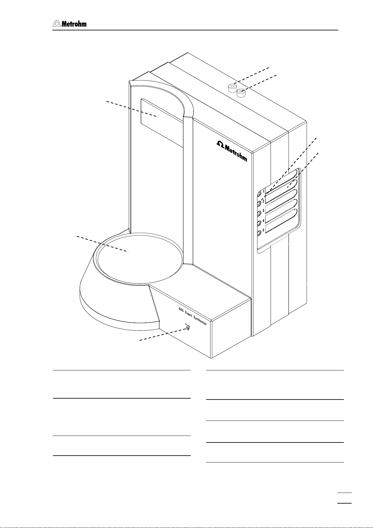
1.2.2 Front of 2.845.0020
7
4
3
5
6
2
1
Figure 2: Front of 2.845.0020
1 LED "Power"
Lights up green when the instrument is
switched on.
2 Place for eluent bottle
The eluent bottle is placed here for
preparing the mixture. There is a builtin magnetic stirrer beneath it.
3 Holder for bottle adapter
Holder for bottle adapter
21.
4 Dosino 1 outlet
Outlet for the components from Dosino
1.
5 Connections for components
Connections for components 1 - 5.
6 Recesses for magnetic labels
For identifying components 1 - 5.
Dosino 2 outlet
7
Outlet for components from Dosino 2.
845 Eluent Synthesizer / Instructions for Use 8.845. 8001EN
3
Page 10
1 Introduction
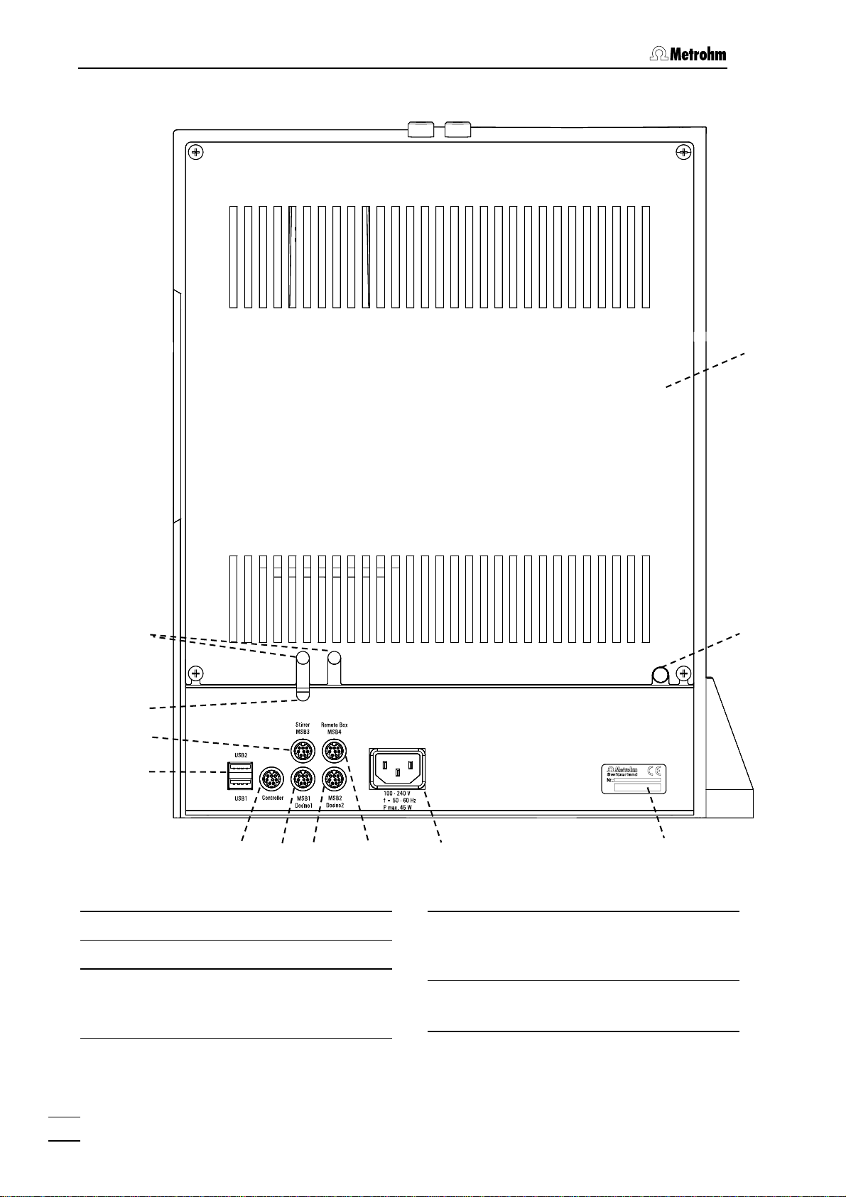
1.2.3 Rear view
19
8
9
10
11
12
13
14
Figure 3: Rear view of 845 Eluent Synthesizer
Lead-throughs for Dosino cables
8
Lead-through for stirrer cable
9
Connection "Stirrer / MSB3"
10
For connecting a stirrer (cable marked
with "Stirrer").
15
16
USB-connections USB1 and USB2
11
USB-ports (type A) for connecting devices with a USB cable.
Controller connection
12
For connecting to a PC.
18
17
4
845 Eluent Synthesizer / Instructions for Use 8.845. 8001EN
Page 11

1.2 Parts and controls
Connection "MSB1 / Dosino 1"
13
For connecting Dosino 1 (cable
marked with "Dosino 1").
Connection "MSB2 / Dosino 2"
14
For connecting Dosino 2 (cable
marked with "Dosino 2") (only for version 2.845.0020).
Connection "Remote Box / MSB4"
15
For connecting the Remote-Box for pH
adjustment with Titrino(s) (see Section
2.6.2).
Mains connection socket
16
Mains connection (see Section
Device type and serial number
17
Connection for drainage tubing
18
For draining off any liquid that has escaped inside the instrument (see Sec-
2.5.2).
tion
Rear panel
19
2.2).
845 Eluent Synthesizer / Instructions for Use 8.845. 8001EN
5
Page 12
1 Introduction
1.3 Information on the Instructions for Use
Please read through these Instructions for Use carefully before you put
the 845 Eluent Synthesizer into operation. The Instructions for Use
contain information and warnings to which the user must pay attention
in order to assure safe operation of the instrument.
1.3.1 Organization
These Instructions for Use 8.845.1003 for the 845 Eluent Synthesizer
provide a comprehensive overview of installation, operation, maintenance, fault rectification and technical specifications of this instrument.
The Instructions for Use are organized as follows:
Sect.
1 Introduction
General description of instrument, parts and controls
and safety notes.
Sect.
2 Installation
Installation of the instrument, mains connection, connection to PC, connection of Dosino(s)/stirrer, pH
controller.
3 «Mix Control» software
Sect.
Explanation of how to use the «Mix Control» software.
Sect.
4 Maintenance - Troubleshooting
Care, cleaning the dosing units, troubleshooting.
Sect.
5 Annex
Technical data, standard equipment, options, warranty, conformity declarations, index.
To find the required information on the instruments, use either the Ta-
ble of contents or the Index at the back.
6
845 Eluent Synthesizer / Instructions for Use 8.845. 8001EN
Page 13
1.3 Information on the Instructions for Use
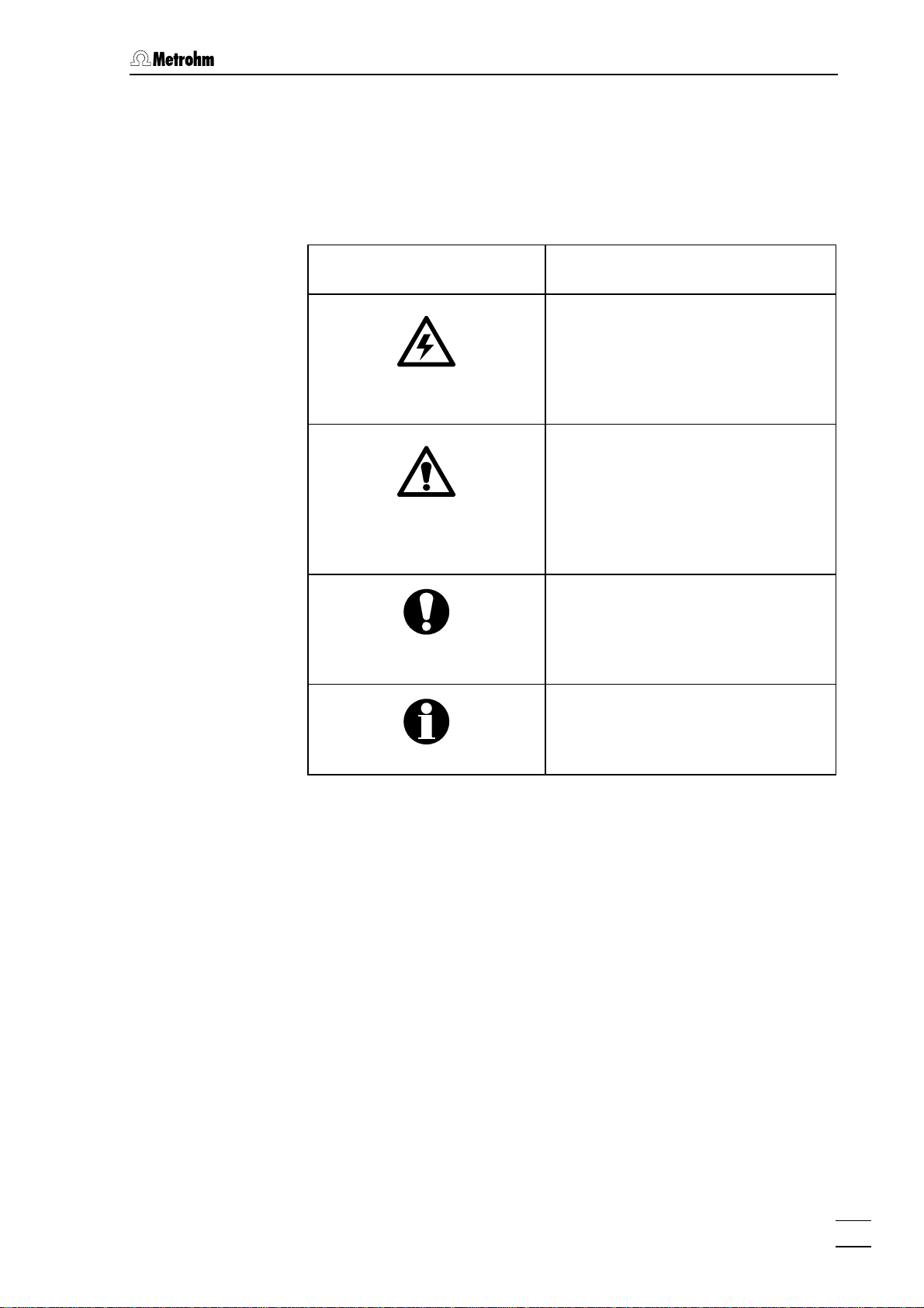
1.3.2 Notation and pictograms
The following notations and pictograms (symbols) are used in these Instructions for Use:
12 Part or control
Hazard
This symbol draws attention to a
possible danger to life or of injury if
the associated directions are not
followed correctly.
Warning
This symbol draws attention to
possible damage to instruments or
instrument parts if the associated
directions are not followed correctly.
Caution
This symbol marks important information. First read the associated
directions before you continue.
Comment
This symbol marks additional information and tips.
845 Eluent Synthesizer / Instructions for Use 8.845. 8001EN
7
Page 14
1 Introduction
1.4 Safety information
This instrument must only be operated in accordance with the information provided in these Instructions for Use.
1.4.1 Electrical safety
While electrical safety in the handling of the 845 Eluent Synthesizer is
assured in the context of the specifications EN / IEC 61010-1, the following points should be noted:
• Electronic parts
Only qualified Metrohm technicians should carry out service work on
electronic components.
• Protection against electrostatic charges
Electronic components are sensitive to electrostatic charges and can
be destroyed by a discharge.
1.4.2 General precautionary rules
• Handling of solvents
Check all lines of the IC system periodically for possible leaks. Follow
the relevant instructions regarding the handling of flammable and/or
toxic solvents and their disposal.
8
845 Eluent Synthesizer / Instructions for Use 8.845. 8001EN
Page 15
2.1 Setting up the instrument
2 Installation
2.1 Setting up the instrument
2.1.1 Packaging
The 845 Eluent Synthesizer is supplied together with the separately
packed accessories in special packagings containing shock-absorbing
foam linings designed to provide excellent protection. Please store all
these special packagings as only they assure transport of the
instrument free from damage.
2.1.2 Check
After receipt, immediately check whether the shipment is complete and
has arrived without damage (compare with delivery note and list of
accessories in Section
structions in Section
5.2). In the case of transport damage, see in-
5.3.1 "Warranty".
2.1.3 Location
This instrument was developed for internal laboratory use; it should not
be used in explosion-endangered locations.
Place the instrument on a suitable vibration-free laboratory bench, protected as much as possible from corrosive atmospheres and contact
with chemicals. Choose a location where the temperature is usually between +5°C and +45°C. The instrument should be protected against
excessive variations in temperature and direct sunlight.
2.2 Mains connection
Mains cable
The instrument is supplied with one of three mains cables
• 6.2122.020 with plug SEV 12 (Switzerland, …)
• 6.2122.040 with plug CEE(7), VII (Germany, …)
• 6.2122.070 with plug NEMA 5-15 (USA, …)
which are three-cored and fitted with a plug with a grounding pin. If a
different plug has to be fitted, the yellow/green lead (IEC standard)
must be connected to protective ground (protection class 1).
Any break in the grounding inside or outside the instrument can make
it a hazard!
Mains connection
Plug the mains cable into mains connection plug
Synthesizer.
845 Eluent Synthesizer / Instructions for Use 8.845. 8001EN
16 of the 845 Eluent
9
Page 16
2 Installation
2.3 Connection to PC
The 845 Eluent Synthesizer is controlled by the «Mix Control» PC software (see Section
System requirements
• Processor: Pentium III
• Main memory: 256 MB RAM
• Free memory space: 100 MB for program files
• CD-ROM drive
• Connection: one free USB slot (type A)
Microsoft Windows
must be used as the operating system.
Installation
To connect the instrument and install the software proceed as follows:
3).
TM
2000 or WindowsTM XP or WindowsTM Vista
1 Installing the «Mix Control» program
• Insert installation CD in CD disk drive.
• If autostart has not
<Start> and Run. Search for the Setup.exe file on the in-
stallation CD and click on
• Click on "
Mix Control" and follow the instructions of the
been activated for the CD drive: select
<OK>.
setup program.
2 Connection 845 - PC
• Connect the 845 Eluent Synthesizer (socket "Controller" 12)
to a USB connection (type A) of your computer with the
6.2151.000 Cable (see the instruction manual for your
computer).
• A system test will automatically be carried out on the 845
Eluent Synthesizer.
• The LED "Power"
1 lights up when the system test has been
completed and the instrument is ready for use.
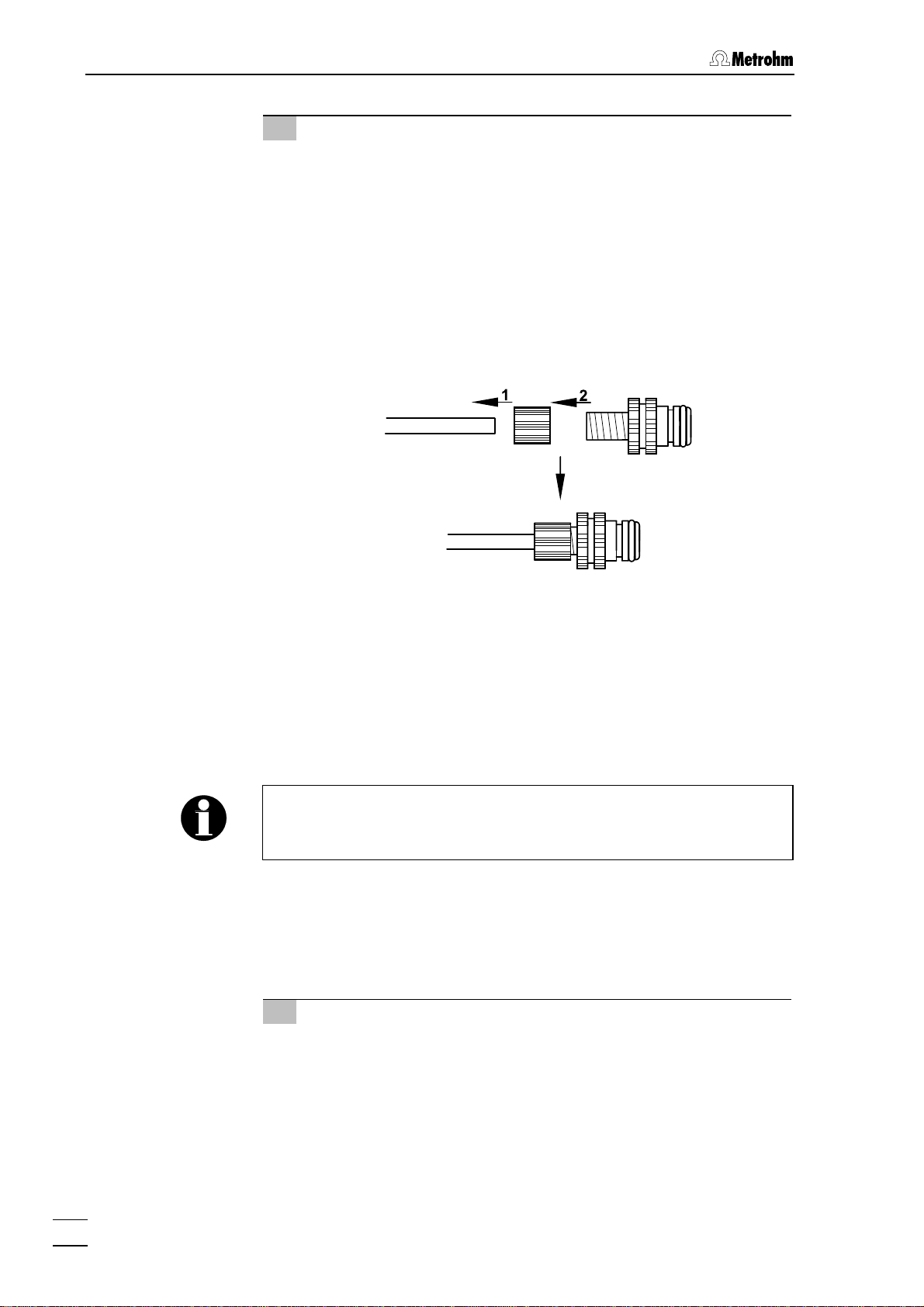
The plug for connection of the 845 Eluent Synthesizer is fitted with a
"pull-out protection device" which prevents the cable from being
pulled out accidentally. When you wish to insert or remove the plug
you must first pull back the outer plug sleeves (marked with arrows).
You can extend the connection with a commercially available USB extension cable (type A/m – type A/f). The length of the connection
should not exceed 5 m. If you require a longer connection then you
must use a USB signal amplifier. Up to five USB signal amplifiers can
be connected in series; this allows a maximum extension of 25 m.
10
845 Eluent Synthesizer / Instructions for Use 8.845. 8001EN
Page 17
2.4 Dosino(s)/Stirrer connections
3 Start the «Mix Control» program
• Double click on the icon of the «Mix Control» software.
• The device is recognized automatically.
2.4 Dosino(s)/Stirrer connections
Dosino(s) and stirrer are part of the instrument. The instrument is supplied with them already connected up; these connections should not be
altered.
Correct connection:
Cable markings Connection markings
Dosino 1
Dosino 2
Stirrer
2.5 Tubing connections
The drainage tubing (Section 2.5.2) and the component inlets and outlets (Sections
2.5.3/2.5.4) must be connected.
MSB1
Dosino 1
MSB2
Dosino 2
Stirrer
MSB3
845 Eluent Synthesizer / Instructions for Use 8.845. 8001EN
11
Page 18
2 Installation
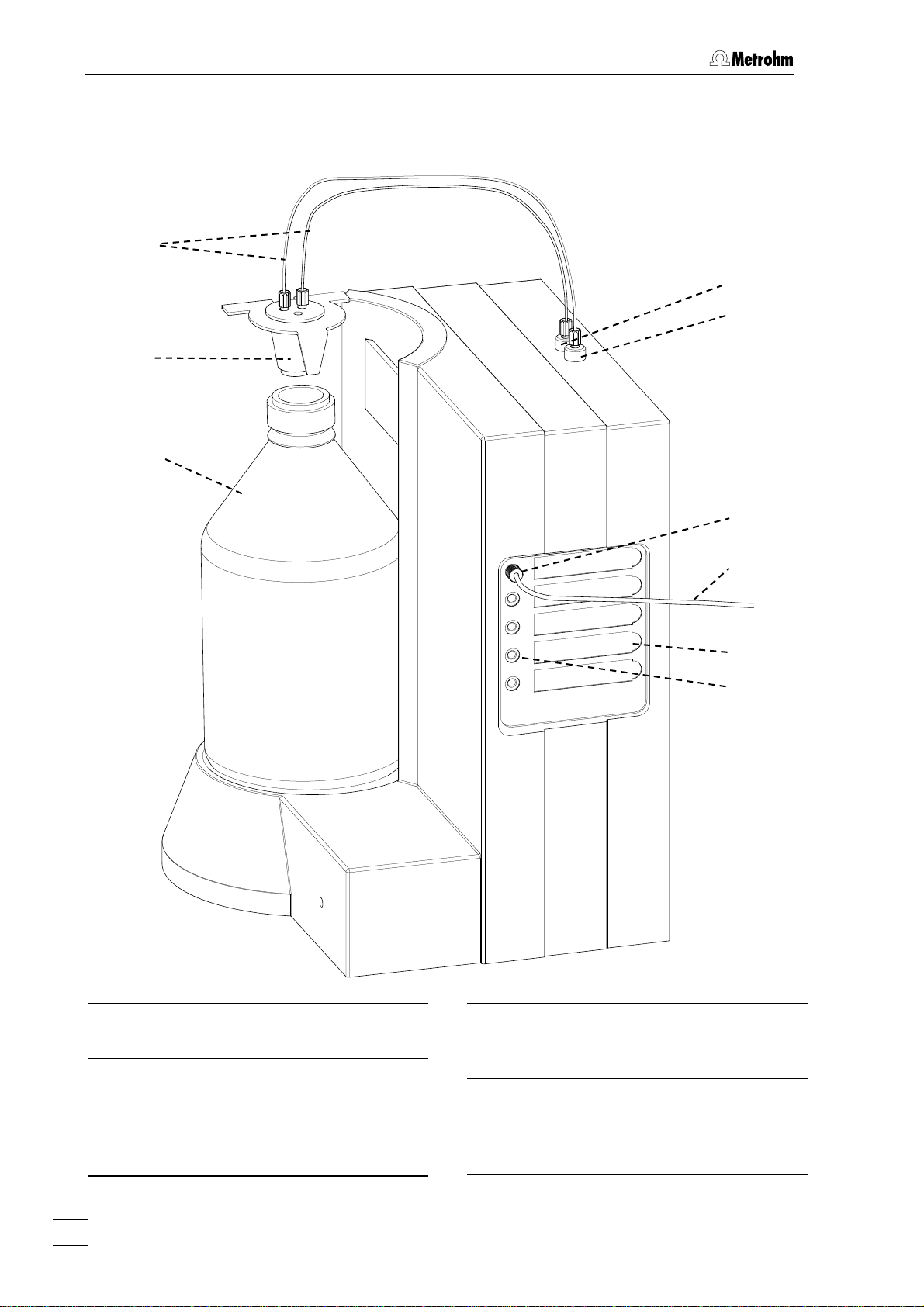
2.5.1 Instrument with tubing connections
20
7
4
21
22
23
24
6
5
Figure 4: Tubing connections
4 Dosino 1 outlet
Outlet for components from Dosino 1.
5 Connections for components
Connections for components 1 - 5.
7 Dosino 2 outlet
Outlet for components from Dosino 2
(only for version 2.845.0020).
FEP tubing connection
20
6.1838.000 Tubing connections for
6 Recesses for magnetic labels
For identifying components 1 - 5.
12
845 Eluent Synthesizer / Instructions for Use 8.845. 8001EN
connecting "Dosino 1 outlet"
ino 2" outlet
7 to the bottle adapter 21.
4 / "Dos-
Page 19
2.5 Tubing connections
Bottle adapter
21
6.1602.180 Bottle adapter as connection piece between eluent bottle
and tubing connection
Eluent bottle
22
6.1608.070 Clear glass bottle for the
mixed eluent.
20.
22
23
24
2.5.2 Connecting the drainage tubing
Connect 6.1816.020 Silicone tubing to connection 18 on the rear panel
of the 845 Eluent Synthesizer and place the other end in a waste bottle.
2.5.3 Connections to bottle adapter
The tubing should not dip into the produced mixture. Make sure that
the FEP- Tubing Connection 6.1838.000
into the bottle.
2.845.0010:
Connect 6.1838.000 FEP Tubing connection
Bottle adapter and to Dosino outlet
the Eluent bottle 6.1608.070.
Pressure screw
6.2744.170 Pressure screw for connecting component capillary
component connection
PTFE capillary
6.1803.130 Capillary for connecting the
components.
20
does not loom too deep
20 to the 6.1602.180 21
4. Then, attach the Bottle adapter to
24 to
5.
2.845.0020:
Connect two 6.1838.000 FEP Tubing connections
21 Bottle adapter and to Dosino outlets 4 and 7. Then, attach the Bottle
adapter to the Eluent bottle 6.1608.070.
2.5.4 Connecting the components
The main component (e.g. water) must be connected to the component connection with the number 1 (see Section
component is used (at the end of the mixing process) to make the
volume up to the total volume given in the method (see Section
3.3).
Proceed as follows to connect the various components:
1 Connect capillary to 845
Connect 6.1803.130 PTFE capillary 24 with 6.2744.170 Pressure
screw 23 to component connection 5.
20 to the 6.1602.180
3.4.2). The main
845 Eluent Synthesizer / Instructions for Use 8.845. 8001EN
13
Page 20
2 Installation
2 Connect capillary to the components
Components from a bottle:
• Insert 6.1803.130 PTFE tubing
ment into the component bottle (e.g. the combination
6.1602.160 bottle attachment GL 45 and 6.1608.030 bottle;
see Optional accessories section 5.2.4).
Components from an MPak (from Chata Biosystems, see section
5.2.5):
• Push the 6.1808.200 MPak coupling onto 6.1803.130 PTFE
tubing 24 by loosening the screw cap from the coupling
and pushing the smaller opening over the tubing. Then
screw the coupling into the cap:
24 through the bottle attach-
• Click the 6.1808.200 MPak coupling onto the lower outlet of
the MPak.
2.6 pH Controller
The pH of the prepared mixture can, if necessary, be adjusted automatically by using the (optional) extension kit. If the pH is to be adjusted
from one side then one pH Controller is required, adjustment from both
sides (without changing the titrant solution) requires two pH Controllers.
We recommend the use of 702 Titrinos as pH Controllers (for supply
package see Section
package for required accessories see Section
2.6.1 Tubing connection for pH Controller
If the pH is to be adjusted automatically after the mixing process then
adaptations are required to the tubing connections to the 845 Eluent
Synthesizer.
5.2.3). Other Titrinos can also be used (supply
5.2.3).
1 Replace bottle adapter 21
6.1602.180 Bottle adapter 21 must be replaced by 6.1602.190
Eluent bottle head.
• Screw off the 6.1838.000 FEP tubing connection(s)
6.1602.180 Bottle adapter 21.
• Screw the 6.1838.000 FEP tubing connection(s)
thread(s) of 6.1602.190 Eluent bottle head.
14
845 Eluent Synthesizer / Instructions for Use 8.845. 8001EN
20 from
20 to M6
Page 21
2.6 pH Controller
2 Install tubing connection to pH Controller
6.1838.010 FEP tubing connection should be used to make
the tubing connection to the pH Controller.
• Insert the black O-ring belonging to the 6.1838.010 FEP
tubing connection into an M6 thread of 6.1602.190 Eluent
bottle head.
• Then push the tip of the 6.1838.010 FEP tubing connection
through the O-Ring and M6 thread.
• Attach the 6.2726.090 Antidiffusion micro-valve to the tip of
the 6.1838.010 FEP tubing connection.
• Connect the other end of the 6.1838.010 FEP tubing connection to the pH Controller (see Instructions for Use –
Exchange Unit).
3 Screw on bottle adapter
• Now screw 6.1602.190 Eluent bottle head onto eluent bottle
22.
806
4 Insert the Aquatrode in the Eluent bottle head
• Insert 6.0257.020 Aquatrode into the large opening of the
6.1602.190 Eluent bottle head. Watch out, that the Aquatrode looms deep enough into the mixture when the pH is
measured.
2.6.2 pH Controller cable connection
The methods at the pH Controller are started via a remote signal from
the 845 Eluent Synthesizer (see Section
ler to the 845 Eluent Synthesizer as follows:
1 Connect Remote Box
• Connect the 6.2148.010 Remote Box to connection "Remote Box / MSB4"
2 Connect pH Controller
• Connect 6.2141.210 Cable to the remote output of
6.2148.010 Remote Box.
• Connect the end of the 6.2141.210 Cable marked A
remote input of the pH Controller.
• Connect the end of the 6.2141.210 Cable marked B
remote input of the second pH Controller.
The Metrohm 702 Titrino can be used with the SET method to set the
pH to a defined value (see the Instructions for Use of the corresponding Titrino).
3.3.3). Connect the pH Control-
15.
to the
to the
The method for the pH-adjustment and the corresponding parameters
have to be defined on the pH-Controller. The pH-adjustment is started
by a remote signal sent from the 845 Eluent Synthesizer to the pHController. For the installation and operation of the pH Controllers
please refer to the corresponding Instructions for Use.
845 Eluent Synthesizer / Instructions for Use 8.845. 8001EN
15
Page 22
3 «Mix Control» software
3 «Mix Control» software
The 845 Eluent Synthesizer is controlled with the «Mix Control» PC
software provided. This section explains the ideas behind the software
and how to use it. For further information please consult the online help
of the software.
3.1 Introduction to the software
3.1.1 The principle of «Mix Control»
What and how much is to be mixed in which ratio is defined via Depot
(see section
Components (see section
specified. The Method is the recipe for preparing the mixture.
3.1.2 Procedure after the first start of «Mix Control»
3.4.1) and Method (see section 3.3). In the Depot the
3.4.2) connected to the instrument are
1. Define the Users (see section 3.4.5).
2. Draw up and save the configuration for the Depot (see section
3.4.1).
3. Draw up and save a Method (see section
After carrying out these steps you can already start mixing processes
(with
In the next step you should define the settings for Directories, Re-
ports, Rinsing and GLP.
).
3.2 Main Window
3.2.1 Menus
Menu File
New... Method /
For creating and configuring a new Method. The parameters of the Method are set to the default values.
3.3).
New... Depot
For creating and configuring a new Depot. The DEPOT
window opens.
Save Method /
For saving the current Method under a new name.
Save Method as...
For saving the current Method under a new name.
16
845 Eluent Synthesizer / Instructions for Use 8.845. 8001EN
Page 23

3.2 Main Window
Open... Method /
For opening a saved Method (see section 3.3).
Open... Depot
For opening a saved Depot.
Print... /
For printing the current Method. The sections selected
in the
REPORT CONFIGURATION window (without the
Produced Composition section) get printed. No preview
is shown.
Print Preview...
Opens the print preview for the current Method (without the Produced Composition section). A printout can
be made directly from the preview.
Printer Configuration...
Opens the PRINTER window. In the PRINTER window
the printer settings can be adapted.
A Report of a previous mixing process can be printed
out via the
Logout... /
Logs out the User. The LOGIN window opens so that a
(active) User can log in.
Quit...
Closes the software.
Menu Configuration
Depot...
Opens the DEPOT window (see section 3.4.1).
System...
Opens the SYSTEM SETTINGS window (see section
3.4.3).
Report...
REPORT LIST window.
Opens the REPORT CONFIGURATION window (see sec-
3.4.4).
tion
User Admin...
Opens the USER ADMINISTRATION window (see section
3.4.5).
Rinsing...
Opens the RINSE window (see section 3.4.6).
845 Eluent Synthesizer / Instructions for Use 8.845. 8001EN
17
Page 24

3 «Mix Control» software
Menu Extras
Sign Method...
Opens the SIGNATURE window (see section 3.5.1).
Audit trail...
Opens the AUDIT TRAIL window (see section 3.5.2).
Report...
Opens the REPORT LIST window (see section 3.5.3).
GLP Manager
Opens the GLP MANAGER window (see section 3.5.4).
Firmware Update
Opens the FIRMWARE UPDATE window (see section
3.5.5).
Service
Opens the LOGIN SERVICE window (see section 3.5.6).
Menu Help...
Help Topics...
Info
Opens the Online Help.
Opens the ABOUT window.
18
845 Eluent Synthesizer / Instructions for Use 8.845. 8001EN
Page 25

3.2 Main Window
3.2.2 Description of the symbols
/ New... Method
For creating and configuring a new Method. The parameters of the Method (see section
default values.
/ Open... Method
For opening a saved Method.
/ Save Method
Saves the current Method.
/ Print...
For printing the current Method. The sections selected
in the
REPORT CONFIGURATION window (without the
Produced Composition section) get printed. No preview
is shown.
3.3) are set to the
845 Eluent Synthesizer / Instructions for Use 8.845. 8001EN
19
Page 26

3 «Mix Control» software
/ Logout...
Logs out the user. The LOGIN window opens so that an
(active) User can log in.
/ Start
Starts the mixing process.
/ Stop
Stops all actions.
/ Rinse
Starts the rinsing process.
To move the symbol strip, click on the dotted bar and move it to the
desired position. The position is saved.
3.3 Method
3.3.1 General information about methods
The method is configured and shown on the Main Page.
The method is the recipe for preparing the mixture. The amounts/concentrations and the
fined and saved in the method. The
the pH-adjustment are also saved with the method.
Number, names and units of the Components are specified in the
Depot.
The calculated volumes of the Components (except for Component 1
see section
used to fill up to the
3.3.2 Parameters
Current Method [ ]
Description [ ]
3.4.2) are added in succession. At the end Component 1 is
Total Volume of the mixture to be produced are de-
Total Volume.
Name of the currently loaded method.
Stirrer Speed and the settings for
Notes about the currently loaded method.
Component X [ ]
Components (see section 3.4.2) with names and units
(they correspond to the Components specified in the
loaded Depot).
20
845 Eluent Synthesizer / Instructions for Use 8.845. 8001EN
Page 27

3.3 Method
Total Volume mL [ 200...5000 ; 200 ]
Volume (in mL) to be prepared in the course of a mixing
process.
Changing the Total Volume does not affect the ratio
of the Components mixed. The numerical values of
the Components given with the (absolute) unit mL are
adapted automatically.
Stirrer Speed [ -15...15 ; 4 ]
Speed of the stirrer.
/
Switch on / switch off stirrer.
3.3.3 pH Adjustment
General information about pH adjustment
pH adjustment is always carried out after the main component has
been added (i.e. at the end of the mixing process).
For automatic pH adjustment 702 Titrinos from Metrohm are intended
for use. If the pH needs to be adjusted from both sides (without
changing the pH-Controller liquid), two 702 Titrinos are required as
pH-Controllers.
In the fields pH-Adjustment and pH-Controller define whether and how
the pH is to be adjusted.
If autonomous is selected for pH-Adjustment then none must not
be selected for pH-Controller. For autonomous a pH-Controller
must be used.
When starting the mixing process (by clicking on
the stirrer is always switched on.
Opens the window PH-ADJUSTMENT CONFIGURATION.
)
Window "pH-Adjustment Configuration"
The dialog window
by clicking on the button
In the
PH-ADJUSTMENT CONFIGURATION window the pH adjustment
PH-ADJUSTMENT CONFIGURATION can be opened
in the Main Window.
procedure can be defined.
845 Eluent Synthesizer / Instructions for Use 8.845. 8001EN
21
Page 28

3 «Mix Control» software
No [ 1 ; display only ]
Number of the Component (see section 3.4.2).
Component
Name of the Component.
pH-Adjustment
none
No pH adjustment will take place.
with request
pH adjustment will take place. It can be carried out
manually or automatically (702 Titrinos from Metrohm
are recommended). After pH adjustment the
PLAY
window opens in which the volume added for pH
LIVE DIS-
adjustment should be entered. This added volume is
taken into account in the volume calculations of the
mixing process.
The titration volume should be below 10 mL. Titration
volumes above 10 mL result in an increased Total
Volume.
autonomous
pH adjustment will take place. It will be carried out
automatically (702 Titrinos from Metrohm are recommended). A pH-Controller must be selected. The
added volume will not be taken into account in the
volume calculations of the mixing process.
pH-Controller (see section 2.6)
none
pH adjustment is carried out manually (must not be selected if
ment
pH-Controller A
autonomous has been selected for pH-Adjust-
).
The pH is adjusted with the instrument that is connected
with the cable end marked A (of the two-headed
6.2141.210 Cable).
pH-Controller B
The pH is adjusted with the instrument that is connected
with the cable end marked B (of the two-headed
6.2141.210 Cable).
22
845 Eluent Synthesizer / Instructions for Use 8.845. 8001EN
Page 29

3.4 Configuration
Details Of pH-Adjustment
Field for notes about the pH adjustment that can be included in the report (see section
3.4.4), e.g. set pH
value, solution used, etc.
3.3.4 Creating a method
There are 2 ways of creating a method:
• Editing an existing method and saving it under a new name
• Creating a completely new method (by clicking on
menu
File, New... Method)
Procedure for configuring a method:
1. Enter the
Total Volume to be produced.
2. For all Components (except for
3.4.2) enter the desired amount/concentration.
3. Enter the
Stirrer Speed.
4. If you want to adjust the pH: configure the pH-adjustment.
5. Save the method.
3.4 Configuration
3.4.1 Depot
General information about Depot
The dialog window
The Components (see section
need to be defined in the Depot. The numbers correspond to the numbers of the Component connections
or via the
Component 1, see section
DEPOT can be opened via Configuration, Depot....
3.4.2) connected to the instrument
5 on the instrument.
Window "Depot"
Define and describe each Component connected to the instrument
under the corresponding number. Save the Depot you have drawn up
as a
.meco file. The settings in the Depot must always be edited when
alterations are made to the connected Components.
The Methods (see section
loaded when they were drawn up. This means that overwriting an existing Depot influences the Methods that are based on this Depot.
In order for the mixing process to supply the desired result, the Com-
ponents specified in the Depot must correspond to the Components physically connected to the instrument. The concentrations/-
amounts defined in the Depot will be used for the volume calculations
in the Method.
845 Eluent Synthesizer / Instructions for Use 8.845. 8001EN
3.3) are based on the Depot that was
23
Page 30

3 «Mix Control» software
No. [ 1...5 ; display only ]
Number of the Component.
The number under which the components are defined here must be the same as that of the connection
(
5
) which the components are connected to.
Component [ Component name ]
Name of the Component (see section 3.4.2). You can
choose it from a selection list or enter it yourself.
Only Components with a defined Component name
are displayed in the Method part of the Main Window
(see section
3.3). If the Component name is deleted,
the Component is not displayed in the Method part
of the Main Window anymore (that does not apply for
Component 1, which can not be deleted ).
Concentration [ 1...20000 ; 0.0 ] (for unit mmol/L) ; [ 1...800000 ; 0.0 ]
(for unit mg/L)
Numerical value for concentration.
Unit [ mmol/L, mg/L, %, mL ;mmol/L ]
Unit for the given concentration/amount. This Component's unit will also be adopted in the Main Window.
Manufacturer [ Name of manufacturer ]
Name of the manufacturer of the Component. You can
choose it from a selection list or enter it yourself.
Date Of Expiry [ Date ; current date ]
Expiry date of the Component. If you click on the field
the Date window opens, in which you can select the required date. If the current date is later than one of the
defined expiry dates then a message will be shown at
the start of a mixing process.
Date Of First Use [ Date ; current date ]
Date of the first use of the Component. If you click on
the field the Date window opens, in which you can select
the required date.
24
845 Eluent Synthesizer / Instructions for Use 8.845. 8001EN
Page 31

3.4 Configuration
Note [ empty ]
Notes field for the Component (e.g. for pH information).
Max. 254 characters.
3.4.2 Components
General information about components
Components are defined in the Depot (see section
3.4.1) .
Components as related to the «Mix Control» software are the liquids
which are connected to the instrument.
Relationship Dosinos - Components
Dosinos form part of the instrument and are responsible for the accurate delivery of the particular volumes of the Components. They are attached to 50 mL Dosing Units.
Whether your instrument is equipped with one or two Dosinos depends
on the particular instrument version. Version 2.845.0010 has one Dosi-
no, Version 2.845.0020 two Dosinos.
The Component connected to connection 1 ("Component 1") is the
Main Component (in the case of two Dosinos, it is the Main Component for both Dosinos). After the end of an action (mixing or rinsing) the
Dosino is always filled with the Main Component (except after a rinsing process "Empty components" with activated Main Component:
the Dosino is then empty).
Dosino 1 Dosino 2
Main Component Component 1 Component 1
Further Components
Component 2 Component 4
Component 3 Component 5
The number of the component correspond to the number of the component connection
5.
For the work with version 2.845.0020:
If two Components - in addition to the Main Component - are used,
it is recommended to connect these two Components to the same
Dosino (Connections 2 and 3, or 4 and 5).
Main Component (Component 1)
The following conditions apply for the Main Component:
• In the Depot the
Component 1 must always be defined as it is
used (at the end of each mixing process) to fill to the
given in the Method (see section
• The volume calculated in the Method for
least 70 mL if one Dosino is used; with two Dosinos it must be at
least 140 mL.
3.3).
Component 1 must be at
Total Volume
845 Eluent Synthesizer / Instructions for Use 8.845. 8001EN
25
Page 32

3 «Mix Control» software
3.4.3 System Settings
General information about system settings
Check the default folders. If you wish to use different folders then, in order to save the file in the required folder, enter the Depot (
Method (
format for exporting Reports (
.meme), the raw data of the prepared mixture (.meda) and the
.pdf or .xml). You can search through the
.meco), the
workplace by clicking on the
button.
Window "System Settings"
The dialog window
tion, System...
In the
SYSTEM SETTINGS window the directories are defined in which
SYSTEM SETTINGS can be opened via Configura-
.
the generated files are to be saved. The software
also set here.
dialog language is
Depot Directory [ ]
Directory for saving a Depot (see section 3.4.1).
Method Directory [ ]
Directory for saving a Method (see section 3.3).
Raw Data Directory [ ]
Directory for saving the data of a mixing process.
Export Directory [ ]
Directory for the Export of a Report (see section 3.5.3).
Dialog language [ English, German ]
Selects the language for the software interface. Any alteration to the language will only become effective for
the Main Window after the software has been restarted.
26
845 Eluent Synthesizer / Instructions for Use 8.845. 8001EN
Page 33

3.4 Configuration
3.4.4 Report Configuration
General information about report configuration
In the
REPORT CONFIGURATION window the settings for generating
the reports are defined.
Select everything that is to appear in the report. There are two predefined presentations (
Standard / Full Report). If you want to create your
report differently you can also select the sections individually (
ized
).
You should also define what is to be done with the data when the mixture has been prepared. You can print out the data automatically or ex-
port it as a PDF- or XML-file.
Window "Report Configuration"
The dialog window
figuration, Report...
REPORT CONFIGURATION can be opened via Con-
.
Custom-
Selection box [ Standard, Full Report, Customized ]
Standard
The sections
duced Composition
Full Report
Identification, Method, Depot and Pro-
are shown in the report.
All sections are shown in the report.
845 Eluent Synthesizer / Instructions for Use 8.845. 8001EN
27
Page 34

3 «Mix Control» software
Customized
The activated sections are shown in the report.
Identification
Information about User, report and program version.
Depot
Information about the Depot used (see section 3.4.1).
Method
Information about Method (see section 3.3), method parameters, concentrations/amounts.
Produced Composition
Information about the mixing process.
Hardware
Information about the hardware used.
GLP Data
Logo
Print Report
Preview
Information about GLP tests and service work to be
carried out (see section
3.5.4).
The selected logo will be shown at the top right of the
report.
Selects the logo graphics (possible file formats: .jpeg or
.gif). Clicking opens the OPEN window, in which the
workplace can be searched. After selection the logo will
be shown to the left of the button.
The report is printed out on the defined default-printer
(Windows: Start/Settings/Printer) as soon as the mixture
has been prepared (if Preview has been activated a
preview
is shown before printing takes place).
print
A print preview is shown before printing takes place.
Export Report As PDF
The report is exported as soon as the mixture has been
prepared as a PDF-file into the directory chosen below.
Export Report As XML
The report is exported as soon as the mixture has been
prepared as an XML-file into the directory chosen below.
28
845 Eluent Synthesizer / Instructions for Use 8.845. 8001EN
Page 35

3.4 Configuration
After the mixture has been prepared the mixture data is saved automatically as a .meda-file in the Raw data folder. If Export Report As
PDF/XML has been activated then it will also be saved in the corresponding file format in the Export Directory selected in the window
SYSTEM SETTINGS.
If you have not activated Print Report or Export Report As
PDF/XML the reports can still be printed out or exported as a PDF- or
XML-file later via the
REPORT LIST window (see section 3.5.3).
3.4.5 User Administration
Window "User Administration"
The dialog window
guration, User Admin...
In the
USER ADMINISTRATION window the users are defined and
USER ADMINISTRATION can be opened via Confi-
.
managed.
As long as no user has been defined the software can be opened
without Login. We recommend that the users are defined immediately after the software has been opened for the first time.
User
Short name of the user. This short name is always to
be entered when the User logs in.
Full Name
First or given name and last or family name of the user.
845 Eluent Synthesizer / Instructions for Use 8.845. 8001EN
29
Page 36

3 «Mix Control» software
Active
Only users set to "active" can log in.
Admin.-rights
Only Administrators have the following rights:
• Depot editing (see section
• System Settings editing (see section
• Report Configuration editing (see section
3.4.1)
3.4.3)
3.4.4)
• User administration
• Drawing up and saving methods (see section
3.4.6)
• Signing methods (see section
• Audit trail opening (see section
• GLP Manager opening (see section
• Firmware update (see section
3.5.1)
3.5.2)
3.5.4)
3.5.5)
Inserts a new line in the user table in which a new user
can be defined.
Prints a list with the selected (blue highlighted) users.
Opens the
PASSWORD window.
The button Password is only active, if at least one user with Administrator rights is defined and active.
Define user
After the software has been opened for the first time define an Administrator as the first user:
1. Click on
2. Enter the
3. Activate
4. Click on [OK]. The
User and Full name.
Active and Admin.-rights.
LOGIN window opens.
5. Enter the previously defined User. Leave the
. A new line will be shown.
Password field
empty.
6. Now edit the password. Click on
PASSWORD
window opens.
. The CHANGE
7. Leave the
word under
[OK]. A return is now made to the
30
845 Eluent Synthesizer / Instructions for Use 8.845. 8001EN
Old Password field empty. Enter the required pass-
New Password and Confirm Passw..., and click on
LOGIN window.
Page 37

3.4 Configuration
8. Enter the previously selected password under Password and click
on [OK].
After the definition of the first user there must always be at least one
user with Administrator rights who is active.
Now (or later as necessary) define new users (with or without Administrator rights).
1. Open the
USER ADMINISTRATION window.
2. Click on
3. Enter the
User and Full Name.
4. When necessary, activate
5. Click on [OK].
The defined users can set their Passwords after they log in for the
first time.
Define if a password is required for login.
1. Click on
PASSWORD window appears.
The
2. Define if a password is required for login.
3. Define password expiry period.
Password
. A new line will be shown.
Active and Admin.-rights.
.
In the
PASSWORD window, the administrator defines whether a pass-
word is required for login.
Additionally, if a password is required for login, the administrator can
set an expiry period for the password.
This setting applies to all users and administrators.
Login with password
Login is only possible with a valid password.
At next login, a password must be created in the
CHANGE PASSWORD window.
845 Eluent Synthesizer / Instructions for Use 8.845. 8001EN
31
Page 38

3 «Mix Control» software
Password expires every ... days
Password expires every [365] days.
Selection box
1...[365]...999
Expiry period of the password.
If the password expires, the user/administrator will receive a message
reminding him to change the password.
Login
The
LOGIN window appears when the software is started (provided that
at least one User has already been defined), as well as for the definition of the first User (the first defined user must be an Administrator).
Login:
Enter the
User and Password and click on [OK].
Change password:
Click on
32
845 Eluent Synthesizer / Instructions for Use 8.845. 8001EN
. The CHANGE PASSWORD window opens.
Page 39

3.4 Configuration
Change Password
The
CHANGE PASSWORD window opens when the but-
ton is clicked on in the
LOGIN window.
Proceed as follows to change the password:
3.4.6 Rinse
General information about rinse
Window "Rinse"
1. Enter your password under
Old Password.
2. Enter your new password under
Password
.
3. Click on [OK].
In the
RINSE window the rinsing process is defined (the rinsing pro-
cess is triggered by clicking on the
Decide which
components
mode is to be used - Prepare components or Empty
- and for which Component(s) the rinsing process is to
be carried out.
The dialog window
RINSE can be opened via Configuration, Rinsing....
New Password and Confirm
button in the Main Window).
845 Eluent Synthesizer / Instructions for Use 8.845. 8001EN
33
Page 40

3 «Mix Control» software
Mode
Economy
Component X
Prepare components
The
mode "Prepare components" is used in the rinsing
process.
Empty components
The
mode "Empty components" is used in the rinsing
process.
If Economy has been activated then the Dosino contents
(is always the Main Component, after an action has
been completed) will be ejected into the component
container at the start of the rinsing process. If
my
has not been activated then the Dosino contents will
Econo-
be ejected in the usual way and can be collected in a
waste container.
Economy is intended for circumstances in which the
Main Component has to be used very sparingly.
The Components (see section 3.4.2) configured in the
Depot (see section
3.4.1) are listed. The rinsing process
is always carried out for those Component(s) that have
been set as
active.
Rinsing Mode "Empty components""
The rinsing mode "
window under the parameter
What effect has a rinsing process with
34
845 Eluent Synthesizer / Instructions for Use 8.845. 8001EN
Empty components" can be selected in the RINSE
Mode.
Mode "Empty components"?
Page 41

3.4 Configuration
Dosino(s) and component tubing (of the activated
Components) are emptied.
When should a rinsing process with
Mode "Empty components" be
carried out?
• When the instrument is not to be used for a long time (in
this case: activate all Components).
• When a Component is to be removed (in this case: only
activate the particular Component).
How is a rinsing process with
Mode "Empty components" trig-
gered?
1. Configure: in the Rinse window set the parameter
to
Empty components. Select the Components whose
tubing is to be emptied.
2. Start: the rinsing process is started in the Main Window
by clicking on the
button.
What happens during a rinsing process with
nents
"?
Before the start of the rinsing process disconnect all
24
Component connections
Component) from the instrument.
(except those of the Main
Mode
Mode "Empty compo-
1. The cylinder(s) of the Dosino(s) is/are completely emptied.
If in the
RINSE window the parameter Economy has
been activated then the Dosino contents will be
ejected into the component container of the Main
Component.
2. For each of the activated Components (except the
Main Component(s)) 10 mL air will be drawn in and the
Dosing unit emptied. That is done in order to empty the
tubing connections inside the instrument.
3. The Dosino(s) is/are rinsed with the Main Component.
If you have also activated the Main Component:
4. Disconnect the Main Component from the instrument.
5. From the Main Component 10 mL (per Dosino) will be
drawn in and the Dosing unit emptied. That is done in
order to empty the tubing connections inside the instrument.
"Rinsing Mode "Prepare components"
The rinsing mode "
window under the parameter
845 Eluent Synthesizer / Instructions for Use 8.845. 8001EN
Prepare components" can be selected in the RINSE
Mode.
35
Page 42

3 «Mix Control» software
What effect has a rinsing process with Mode "Prepare compo-
nents
"?
Air bubbles are removed by rinsing Dosino(s) and
component tubing (from the activated Components)
(see section
3.4.2).
When should a rinsing process with
be carried out?
We recommend that such a rinsing process is carried
out at least once per day, as well as each time that a
new Component has been added. Removal of air
bubbles increases the mixing accuracy.
How is a rinsing process with
Modus "Prepare components" trig-
gered?
1. Configure: in the
Prepare components. Select the Components to be
to
RINSE window set the parameter Mode
"prepared".
2. Start: the rinsing process is started in the Main Win-
dow by clicking on the
How does a rinsing process with
proceed?
1. The cylinder(s) of the Dosino(s) is/are completely emp-
tied.
If in the
RINSE window the parameter Economy is ac-
tivated then the Dosino contents will be ejected into
the component container of the Main Component.
Modus "Prepare components"
button.
Modus "Prepare components"
3.5 Extras
3.5.1 Sign methods
The dialog window SIGNATURE can be opened via Extras, Sign
Method...
In the
Enter your
reason for signing the method and click on [OK].
(only when you are logged in as Administrator).
SIGNATURE window the current Method can be signed.
2. From each of the activated Components 10 mL will be
drawn in and ejected in succession.
3. At the end the Dosino(s) will be refilled with the Main
Component.
user name and your password (see section 3.4.5), select a
36
845 Eluent Synthesizer / Instructions for Use 8.845. 8001EN
Page 43

3.5 Extras
User
Enter User name. You can also enter a user name that is
different from the currently logged in User. Prerequirement: the user is active and has Administrator rights.
Password
Reason [ Selection of standard reasons ]
Comment [ 255 Characters ]
If you change a method and save it, the signature is deleted.
3.5.2 Audit trail
The term Audit trail is used for the protocol of all user actions that
generate, edit or delete data. Each of these actions is saved as a line in
the Audit trail table together with the date, time and name of the
logged-in user.
Window "Audit trail"
AUDIT TRAIL window can be opened via Extras, Audit trail....
The
Enter the password.
Give the reason for signing the method.
Notes about the signature.
845 Eluent Synthesizer / Instructions for Use 8.845. 8001EN
37
Page 44

3 «Mix Control» software
Table headers:
No
Icon
Date
User
Number of the Audit trail entry.
Information about an action that is neither safety-relevant
nor altered any data.
Information about an action that is safety-relevant or with
which data has been altered.
Information about a fault or incorrect action.
Date and time of the action.
Short name of logged-in user.
Category
Program part to which the action belongs.
Action
Short description of the action.
Details
Detailed information about the action.
38
845 Eluent Synthesizer / Instructions for Use 8.845. 8001EN
Page 45

3.5 Extras
Available operations:
File, Export
Exports the Audit trail entries. The folder into which the
Audit trail entries are to be exported can be entered in
the Export window that now opens. With a search of
the workplace can be made.
File, Open
Views an Audit trail file (Log.madt).
In order to save the Audit trail file (Log.madt) a copy
must be generated via a Windows Explorer (..\Mix Control\Data).
File, Delete
Deletes all entries in the Audit trail table. Can only be
carried out when no new entries have been added after
the last Export.
File, Exit
Closes the Audit trail window.
Filter, Quick filter /
Filters the Audit trail table according to selectable criteria.
Select filter criteria:
1. Use the left-hand mouse key to click in a field
whose entry you want to use as a filter criterion,
e.g. "System":
2. Click on
The quick filter can be used again within the filtered
table so that the number of entries can be reduced
step by step.
Filter, Show all /
.
.
Cancels the Quick filter function. All Audit trail entries
are shown.
3.5.3 Window "Report List"
The REPORT LIST window can be opened via Extras, Report List....
REPORT LIST window the data of all prepared mixtures is shown.
In the
845 Eluent Synthesizer / Instructions for Use 8.845. 8001EN
39
Page 46

3 «Mix Control» software
Date/Time
Method
Depot
Description
User
Date and time at which the mixture was prepared.
Name of the Method used for preparing the mixture (see
section
3.3).
Name of the Depot used for preparing the mixture (see
section
3.4.1).
Text that was entered in the Description field in the Main
Page when the mixture was prepared.
Short name of the User logged in when the mixture was
prepared.
Prints out the marked, or all (if none have been marked)
entries in the
report list.
Prints the marked Reports.
40
845 Eluent Synthesizer / Instructions for Use 8.845. 8001EN
Page 47

3.5 Extras
Exports the marked Reports as Pdf-files to the directory
defined in the
Export Directory, see section 3.4.3.
SYSTEM SETTINGS window (parameter
Exports marked Reports as XML-files to the directory defined in the
port Directory
SYSTEM SETTINGS window (parameter Ex-
).
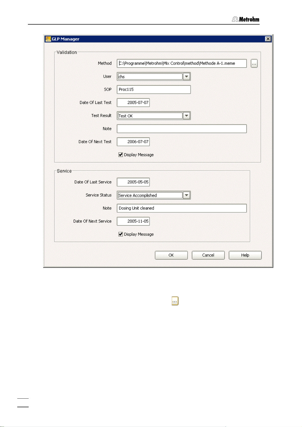
3.5.4 GLP Manager
The dialog window GLP MANAGER can be opened via Extras, GLP
Manager
GLP validations and service work that have been carried out are en-
tered in the
The date of each validation/service work should be entered in the
GLP MANAGER window. In addition, the date for the next validation or
next service should also be entered.
.
GLP MANAGER window.
845 Eluent Synthesizer / Instructions for Use 8.845. 8001EN
41
Page 48
3 «Mix Control» software
Validation:
Method
Information about the Method (see section 3.3) used for
the validation. With
the workplace can be searched
through for Methods.
User
Information about the logged-in User when validation
was carried out.
SOP
Possibility of entering an SOP (Standard Operation
Procedure) name or number.
Date Of Last Test
Date of last validation.
42
845 Eluent Synthesizer / Instructions for Use 8.845. 8001EN
Page 49

3.5 Extras
Test Result [ No Test Accomplished Yet, Test OK, Test not OK ]
Information about the result of the last validation.
Note
Notes about the last validation.
Date Of Next Test
Date for the next validation.
Display Message
If activated: if the current date is later than the date given
for
Date Of Next Test then a message will be shown at
the start of a mixing process.
Service:
Date Of Last Service
Information about date of last service.
Service-Status [No Service Accomplished Yet, Service Accomplished]
Shows whether a service has been carried out.
Note
Notes about the last service.
Date Of Next Service
Date for the next service.
Display Message
If activated: if the current date is later than the date given
for the
shown at the start of a mixing process.
3.5.5 Firmware Update
The FIRMWARE UPDATE window can be opened via Extras, Firmware
Update
Via the
copied to the instrument.
.
FIRMWARE UPDATE window a current Firmware version can be
Date Of Next Service then a message will be
In order to update the instrument Firmware you should first select the
file for the
845 Eluent Synthesizer / Instructions for Use 8.845. 8001EN
Binary-File Path parameter that contains the current Firm-
43
Page 50

3 «Mix Control» software
ware. With you can search through the workplace. Then click on
in order to start Firmware updating.
3.5.6 Login Service
The service section of the software can be accessed via the LOGIN
SERVICE
should carry out work in the service section. It is protected by a special
service password.
window. Only service technicians from a Metrohm agency
44
845 Eluent Synthesizer / Instructions for Use 8.845. 8001EN
Page 51

4.1 Care
4 Maintenance - Troubleshooting
4.1 Care
The 845 Eluent Synthesizer requires adequate care. If it becomes excessively dirty then this could interfere with its functions and shorten the
working life of its robust mechanism and electronics.
Spilt chemicals and solvents must be wiped up immediately. The electrical connections on the rear panel of the instrument should be protected against contamination.
If aggressive media penetrate into the interior of the instrument the
mains plug should be pulled out immediately to prevent massive
damage to the electronics. If such damage does occur then please
contact Metrohm Service.
4.1.1 Decommissioning
Proceed as follows, if the instrument is not to be used for a long time:
1. Connect water to all component connections (
2. Carry out a rinsing process in the "
components should be activated for the rinsing process (see Section
3.4.6).
4.2 Dosing units
Depending on the version, the 845 Eluent Synthesizer has either one
(Version 2.845.0010) or two (Version 2.845.0020) 807 Dosing units
(each with a 50 mL glass cylinder). These are located inside the instrument, screwed onto a pull-out drawer. Each dosing unit is controlled by
an 800 Dosino.
Depending on the solutions used, the dosing units should be cleaned
every 6 to 12 months.
4.2.1 Deinstallation
In order to clean a Dosino it must first be removed from the 845 Eluent
Synthesizer.
5).
Empty components" mode. All
The procedure for deinstallation of the Dosino is as follows:
1 Empty instrument
• Use the «Mix Control» software to carry out a rinsing process in the "Empty components" mode (make sure that all
components have been activated in the RINSE window, see
Section 3.4.6).
2 Remove rear panel
• Remove rear panel 19 by using a screwdriver.
845 Eluent Synthesizer / Instructions for Use 8.845. 8001EN
45
Page 52

4 Maintenance - Troubleshooting
3 Screw off tubing connections
• Screw off all tubing connections from the dosing unit.
4 Loosen attachment
• Loosen thread adapter 26 while holding the dosing unit/Dosino in your other hand.
• Also remove holder plate
27.
25
26
27
28
Figure 5: Dosing unit attachment
Distance ring
25
Thread adapter
26
Holder plate
27
For attaching the tubing connections to
port 2 and 4
4.2.2 Cleaning
Cleaning the 807 Dosing unit is described in the 8.807.1008 Instructions
for Use – 807 Dosing unit, Section 6.
Slip-on nipple
28
For connecting component 1 to port 4
46
845 Eluent Synthesizer / Instructions for Use 8.845. 8001EN
Page 53

4.2 Dosing units
4.2.3 Installation
After cleaning the dosing units should be reinstalled together with the
Dosinos.
Diagram showing connections with one Dosino:
(Dosing unit seen from below)
4
29
30
Figure 6: Connections with one Dosino
Component connection strip
29
Dosing unit (from below)
30
4 Dosino 1 outlet
Outlet for component to be added
(from Dosino 1).
845 Eluent Synthesizer / Instructions for Use 8.845. 8001EN
47
Page 54

4 Maintenance - Troubleshooting
Diagram showing connections with two Dosinos:
(Dosing units seen from below)
Figure 7: Connections with two Dosinos
29 Component connection strip
30 Dosing unit from Dosino 1 (from
below)
Dosing unit from Dosino 2 (from
31
below)
T-piece for component 1
32
For connecting the main component
(see Section
3.4.2)
4 Dosino 1 outlet
Outlet for the component to be added
from Dosino 1.
7 Dosino 2 outlet
Outlet for the component to be added
from Dosino 2.
48
845 Eluent Synthesizer / Instructions for Use 8.845. 8001EN
Page 55

4.3 Troubleshooting
4.3 Troubleshooting
Problem Cause Remedy
Liquids escaping from
drainage tubing or
from bottom of rear
panel.
Components are not
aspirated.
LED "Power" (1) does
not light up when instrument is connected.
Instrument not recognized at software startup (LED "Power" (
lights up)
1)
• Leaking connections
• Leak in instrument
• Leaking or blocked con-
nections
• Dosing units/Dosinos
defect
• Mains cable defect
• Internal power supply
defect
• Instrument not connected to USB
• USB cable defect
1. Stop the current process
2. Remove rear panel
check the connections and dosing units (see Section
1. Stop the current process
2. Check the connections outside
the instrument
3. Remove rear panel
check the connections and Dosinos/Dosing units (see Section
4.2)
• Replace the mains cable
• Contact Metrohm Service
• Connect instrument to USB of
the PC (see Section
• Replace USB cable
19 and
4.2)
19 and
2.3)
845 Eluent Synthesizer / Instructions for Use 8.845. 8001EN
49
Page 56

5 Annex
5 Annex
5.1 Technical data
5.1.1 Interfaces
USB-connections
USB ports 2 USB downstream ports (type A sockets), each 500
mA, for connecting USB devices.
Controller connection
Controller port USB upstream port with additional signals (mini-DIN
socket) for connecting a computer to control the instrument (with 6.2151.000 Cable).
MSB-connections (MSB = Metrohm Serial Bus)
MSB1 Dosino For connecting Dosino 1
MSB2 Dosino For connecting Dosino 2 (if present)
MSB3 Stirrer Connection for built-in stirrer
Stirrer control: switched on/off via «Mix Control» software
(manual or in method).
Selectable speed (15 steps) and direction of rotation.
MSB4 Remote Box For connecting 6.2148.010 Remote-Box for automatic
pH adjustment (see Section
Remote boxes are used to address and control external
devices.
5.1.2 Mains connection
Voltage
Frequency
Power consumption
Fuse
100...240 V (± 10%)
50...60 Hz
max. 45 W
electronic overload protection
5.1.3 Safety specifications
Construction and testing As per EN/IEC/UL 61010-1, CSA 22.2 No. 61010-1 pro-
tection class 1
Safety information These instructions contain safety information that must
be observed by the user in order to guarantee the safe
operation of the instrument.
2.6).
5.1.4 Electromagnetic compatibility (EMC)
Emission Standards complied with:
- EN/IEC 61326
- EN 55022 / CISPR 22
Immunity Standards complied with:
- EN/IEC 61326
845 Eluent Synthesizer / Instructions for Use 8.845.1003
50
Page 57

5.1 Technical data
- EN/IEC 61000-4-2
- EN/IEC 61000-4-3
- EN/IEC 61000-4-4
- EN/IEC 61000-4-5
- EN/IEC 61000-4-6
- EN/IEC 61000-4-11
- EN/IEC 61000-4-14
5.1.5 Ambient temperature
Nominal working range
Automatic inner temperature
monitoring
Storage
Transport
5.1.6 Dosing drive
Resolution
Dosing/Filling rates
5.1.7 Dosing Unit
Volumes of cylinders
Chemical resistance of the
PETG housing
+5 C...+45 C (at max. 85% relative humidity)
> 70°C initial alarm
> 75°C alarm
–20°C...+60 °C
–40°C...+60 °C
10'000 increments per cylinder volume
18 seconds each per cylinder volume
50 mL
Good resistance to:
aqueous solutions, dilute acids, alcohols and hydrocarbons
Limited resistance to:
conc. organic acids, dilute aqueous alkalis (stress
cracks), acetone, isopropanol, tetrahydrofuran, hot
water
Not resistant to:
concentrated inorganic acids and bases, bromine,
chlorinated solvents, phenol, water vapor >100 °C
5.1.8 Reference conditions
Ambient temperature
Relative humidity
Instrument status
+25 °C (±3 °C)
≤ 60%
In operation for at least 30 min
5.1.9 Dimensions
Housing material Polyurethane
Width
Height
Depth
Weight
2.844.0010
2.844.0020
845 Eluent Synthesizer / Instructions for Use 8.845. 8001EN
314 mm
378 mm
280mm
6920 g
7639 g
51
Page 58

5 Annex
5.2 Standard equipment
Subject to changes!
All dimensions are given in mm.
The 845 Eluent Synthesizer is available in the following versions:
• 2.845.0010 845 Eluent Synthesizer with 1 Dosino
• 2.845.0020 845 Eluent Synthesizer with 2 Dosinos
5.2.1 Standard equipment for 2.845.0010
The following parts are supplied under the order number 2.845.0010:
Quantity Order no. Description
1 1.845.0010 Eluent Synthesizer with 1 Dosino
1 6.1546.030 Piston rod
For PTFE piston of Dosing Unit
1 6.1602.180 Bottle Adaptor to 845
Adaptor to the eluent bottle of the Eluent Synthesizer without pH adjustment
1 6.1608.070 Eluent bottle / 2 L / GL 45
Material Clear glass
Height (mm) 262
Volume in mL 2000
3 6.1803.130 Capillary 1/8 in. / 1/16 in. i.d. / 1.5 m
Connecting capillary from the component containers to the Eluent Synthesizer
Material PTFE
Outer diameter in
inches
Inner diameter in
inches
1/8
1/16
845 Eluent Synthesizer / Instructions for Use 8.845.1003
52
Page 59

5.2 Standard equipment
Quantity Order no. Description
1 6.1808.200 Connectors to MPak, set of 3
1 6.1816.020 Silicone tubing 6 mm i.d., 1 m
Drainage tube
Material Silicone rubber
Outer diameter in mm 9
Inner diameter in mm 6
1 6.1838.000 FEP Tubing Connection to 845, 1 x
M6 / 45 cm
Tubing connection from Eluent Synthesizer to eluent bottle adaptor
1 6.1903.060 Teflon Stirring bar 30 mm
Stirring Bar with magnetic core, PTFE
coated, length 30 mm. For Eluent Synthesizer.
1 6.2122.0X0 Mains cable
to customer's specifications:
Cable socket
Type IEC 320/C 13 Type SEV 12 (CH…) 6.2122.020
Type IEC 320/C 13 Type CEE (7), VII (D…) 6.2122.040
Type CEE (22), V Type NEMA 5-15 (USA…) 6.2122.070
Cable connector
1 6.2151.000 Cable USB A - mini-DIN 8P
Cable for connecting the Eluent Synthesizer to the PC (USB connection,
type A)
1 6.2248.010 Magnetic shield , 15 x 68 mm, 3
pieces
1 6.2739.000 Wrench
For tightening nipples.
1 6.2744.170 Pressure screw PEEK UNF 1/4-28, 3
pieces
Fixing connecting capillaries from the
component containers to the Eluent
Synthesizer.
Material PEEK
845 Eluent Synthesizer / Instructions for Use 8.845. 8001EN
53
Page 60

5 Annex
Quantity Order no. Description
1 6.2803.010 Grease (2 g)
Special quality (without silicone). For
grease-free ground joint connections.
1 6.6057.000 845 PC Software Mix Control 1.0 CD
Software for the 845 Eluent Synthesizer.
1 8.800.1003 Instructions for Use 800 Dosino (e)
1 8.807.1008 Instructions for Use 807 Dosing Unit (g, e, f, s)
1 8.845.1003 Instructions for Use 845 Eluent Synthesizer (e)
5.2.2 Standard equipment for 2.845.0020
The following parts are supplied under the order number 2.845.0020:
Quantity Order no. Description
1 1.845.0020 Eluent Synthesizer with 2 Dosinos
1 6.1546.030 Piston rod
For PTFE piston of Dosing Unit
1 6.1602.180 Bottle Adaptor to 845
Adaptor to the eluent bottle of the Eluent Synthesizer without pH adjustment
845 Eluent Synthesizer / Instructions for Use 8.845.1003
54
Page 61

5.2 Standard equipment
Quantity Order no. Description
1 6.1608.070 Eluent bottle / 2 L / GL 45
Material Clear glass
Height (mm) 262
Volume in mL 2000
5 6.1803.130 Capillary 1/8 in. / 1/16 in. i.d. / 1.5 m
Connecting capillary from the component containers to the Eluent Synthesizer
Material PTFE
Outer diameter in
inches
Inner diameter in
inches
2 6.1808.200 Connectors to MPak, set of 3
1/8
1/16
1 6.1816.020 Silicone tubing 6 mm i.d., 1 m
Drainage tube
Material Silicone rubber
Outer diameter in mm 9
Inner diameter in mm 6
2 6.1838.000 FEP Tubing Connection to 845, 1 x
M6 / 45 cm
Tubing connection from Eluent Synthesizer to eluent bottle adaptor
1 6.1903.060 Teflon Stirring bar 30 mm
Stirring Bar with magnetic core, PTFE
coated, length 30 mm. For Eluent Synthesizer
1 6.2122.0X0 Mains cable
to customer's specifications:
Cable socket
Type IEC 320/C 13 Type SEV 12 (CH…) 6.2122.020
Type IEC 320/C 13 Type CEE (7), VII (D…) 6.2122.040
Type CEE (22), V Type NEMA 5-15 (USA…) 6.2122.070
Cable connector
845 Eluent Synthesizer / Instructions for Use 8.845. 8001EN
55
Page 62

5 Annex
Quantity Order no. Description
1 6.2151.000 Cable USB A - mini-DIN 8P
Cable for connecting the Eluent Synthesizer to the PC (USB connection,
type A)
2 6.2248.010 Magnetic shield , 15 x 68 mm, 3
pieces
1 6.2739.000 Wrench
For tightening nipples.
2 6.2744.170 Pressure screw PEEK UNF 1/4-28, 3
pieces
Fixing connecting capillaries from the
component containers to the Eluent
Synthesizer.
Material PEEK
1 6.2803.010 Grease (2 g)
Special quality (without silicone). For
grease-free ground joint connections.
1 6.6057.000 845 PC Software Mix Control 1.0 CD
Software for the 845 Eluent Synthesizer.
1 8.800.1003 Instructions for Use 800 Dosino (e)
1 8.807.1008 Instructions for Use 807 Dosing Unit (g, e, f, s)
1 8.845.1003 Instructions for Use 845 Eluent Synthesizer (e)
845 Eluent Synthesizer / Instructions for Use 8.845.1003
56
Page 63

5.2 Standard equipment
5.2.3 Accessories for pH adjustment (optional)
The following accessory packages are offered under their own order
numbers as an extension to the 845 Eluent Synthesizer for automatic
pH adjustment:
• 2.702.0120 with 702 Titrino
• 6.5329.000 without Titrino
The following parts are supplied under the order number 2.702.0120:
Quantity Order no. Description
1 1.140.0200 Impact printer CUSTOM DP40-S4N
1 1.702.0020 SM Titrino
1 6.0257.020 Aquatrode Plus (30 cm) with Pt 1000
For pH adjustment of eluents at the Eluent Synthesizer.
1 6.1446.000 SGJ stopper / B-14/(15)
Material PP
Height (mm) 30.5
SGJ size B-14/(15)
2 6.1446.040 Thread stopper M6
Material PVDF
Height (mm) 21.5
Outer diameter in mm 4.9
1 6.1602.190 Eluent Bottle Head, 1 x NS 14, 4 x
M6
Eluent bottle head to connect up to 4
tubings with M6 connectors. For eluent
bottle of the Eluent synthesizer.
1 6.1838.010 Connecting Tubing to 845, 85 cm
Connection eluent bottle at the eluent
Synthesizer - Titrino
Material FEP
845 Eluent Synthesizer / Instructions for Use 8.845. 8001EN
57
Page 64

5 Annex
Quantity Order no. Description
1 6.2125.130 Cable RS232, DB25 f / DB9 m
For connecting RS232 interface - printer
1 6.2132.120 Keypad for 702
1 6.2141.210 Cable Remote Box MSB-2 x Titrino
For the connection of up to two Titrinos
to 845
1 6.2148.010 Remote Box MSB
Remote interface for the connection of
Titrinos (via 6.2141.210 Cable).
1 6.2307.230 Buffer solutions pH 4/7/9
Mixed buffer solutions pH
4.00/7.00/9.00 (25 °C) in single use sachets, colorless, box of 3 X 10 x 30 mL
1 6.2308.050 KCl Solution 3 mol/L (50 mL)
845 Eluent Synthesizer / Instructions for Use 8.845.1003
58
Page 65

5.2 Standard equipment
Quantity Order no. Description
1 6.2323.000 Storage solution
Storage solution for all combined pH
glass electrodes with reference electrolyte c(KCl) = 3 mol/L
1 6.2726.090 Antidiffusion valve
For 6.1541.XXX and 6.1543.130,
6.1543.140, 6.1543.150, 6.1543.160,
6.1543.200 antidiffusion buret tips
1 6.2739.010 Wrench
For 6.3011.XXX ... 6.3014.XXX exchange units
1 6.3026.210 Exchange Unit 10 mL
Intelligent dosing unit with 10 mL glass
cylinder and light protection.
PCTFE/PTFE flat stopcock, FEP tubing
connection, antidiffusion buret tip and
standard amber glass reagent bottle
Volume in mL 10
845 Eluent Synthesizer / Instructions for Use 8.845. 8001EN
59
Page 66

5 Annex
The following parts are supplied under the order number 6.5329.000
(for pH-adjustment, no Titrino included):
Quantity Order no. Description
1 6.0257.020 Aquatrode Plus (30 cm) with Pt 1000
For pH adjustment of eluents at the Eluent Synthesizer.
1 6.1446.000 SGJ stopper / B-14/(15)
Material PP
Height (mm) 30.5
SGJ size B-14/(15)
2 6.1446.040 Thread stopper M6
Material PVDF
Height (mm) 21.5
Outer diameter in mm 4.9
1 6.1602.190 Eluent Bottle Head, 1 x NS 14, 4 x
M6
Eluent bottle head to connect up to 4
tubings with M6 connectors. For eluent
bottle of the Eluent synthesizer.
1 6.1838.010 Connecting Tubing to 845, 85 cm
Connection eluent bottle at the eluent
Synthesizer - Titrino
Material FEP
1 6.2141.210 Cable Remote Box MSB-2 x Titrino
For the connection of up to two Titrinos
to 845
1 6.2148.010 Remote Box MSB
Remote interface for the connection of
Titrinos (via 6.2141.210 Cable).
845 Eluent Synthesizer / Instructions for Use 8.845.1003
60
Page 67
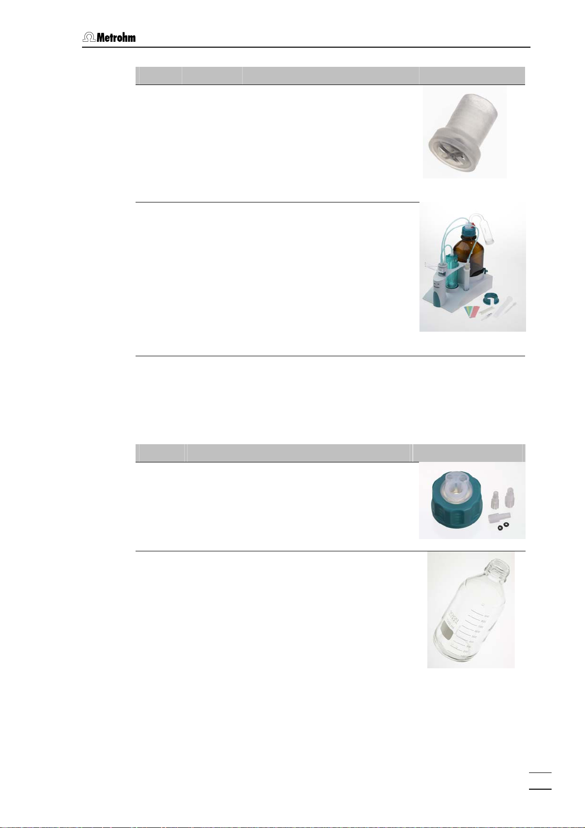
5.2 Standard equipment
Quantity Order no. Description
1 6.2726.090 Antidiffusion valve
For 6.1541.XXX and 6.1543.130,
6.1543.140, 6.1543.150, 6.1543.160,
6.1543.200 antidiffusion buret tips
1 6.3026.210 Exchange Unit 10 mL
Intelligent dosing unit with 10 mL glass
cylinder and light protection.
PCTFE/PTFE flat stopcock, FEP tubing
connection, antidiffusion buret tip and
standard amber glass reagent bottle
Volume in mL 10
5.2.4 Optional accessories
Order no. Description
6.1602.160 Eluent bottle attachment GL 45
For eluent bottles, with connections for absorber
tube and aspiration tubing.
Opening ground joint A-14/15
6.1608.030 Bottle / 1000 mL / GL 45
To Exchange Units.
Material Clear glass
Width (mm) 96
Height (mm) 223
Volume in mL 1000
845 Eluent Synthesizer / Instructions for Use 8.845. 8001EN
61
Page 68

5 Annex
Order no. Description
6.1609.000 Drying tube, large and bent
For Exchange Units and eluent bottle.
Material Glass
Height (mm) 129
Inner diameter in mm 32
SGJ size B-14/15
6.2023.020 SGJ clip
Clip for SGJ 14/16
Material POM
6.2062.000 MPak cabinet
Holder for three MPak eluent bag
5.2.5 Producers of concentrates and standards
This list is not exhaustive.
Producer Internet address
J.T. Baker http://www.jtbaker.com
Chata Biosystems (MPak Reagents) http://www.chatabiosystems.com
Merck http://www.merck.de
Reagecon http://www.reagecon.com
Sigma Aldrich (Fluka, Riedel-de Haën) http://www.sigmaaldrich.com
5.2.6 Systems for producing ultra pure water
Several manufacturers offer systems for producing ultra pure water.
This list is not exhaustive.
Producer Internet address
Millipore http://www.millipore.com
ELGA http://www.elgalabwater.com
Barnsted http://www.barnsteadthermolyne.com/index.cfm
845 Eluent Synthesizer / Instructions for Use 8.845.1003
62
Page 69

5.3 Warranty
5.3 Warranty
5.3.1 Warranty
The warranty on our products is limited to defects that are traceable to
material, construction or manufacturing error which occur within 12
months from the day of delivery. In this case, the defects will be rectified in our workshops free of charge. Transport costs are to be paid by
the customer.
For day and night operation, the warranty is limited to 6 months.
Glass breakage in the case of electrodes or other parts is not covered
by the warranty. Checks which are not a result of material or manufacturing faults are also charged during the warranty period. For parts of
outside manufacture insofar as these constitute an appreciable part of
our instrument, the warranty stipulations of the manufacturer in question
apply.
With the regard to the guarantee of accuracy, the technical specifications in the instruction manual are authoritative.
Concerning defects in material, construction or design as well as the
absence of guaranteed features, the orderer has no rights or claims except those mentioned above.
If damage of the packaging is evident on receipt of a consignment or if
the goods show signs of transport damage after unpacking, the carrier
must be informed immediately and a written damage report demanded.
lack of an official damage report releases Metrohm from any liability to
pay compensation.
If any instruments and parts have to be returned, the original packaging
should be used if at all possible. This applies above all to instruments,
electrodes, burette cylinders and PTFE pistons. Before embedment in
wood shavings or similar material, the parts must be packed in a dustproof package (for instruments, use of a plastic bag is imperative). If
open assemblies are enclosed in the scope of delivery that are sensitive to electromagnetic voltages (e.g. data interfaces etc.) these must
be returned in the associated original protective packaging (e.g. conductive protective bag). (Exception: assemblies with built-in voltage
source belong in a non-conductive protective packaging).
No warranty responsibility whatsoever will be accepted by Metrohm for
damage which arises as a result of non-compliance with these instructions.
845 Eluent Synthesizer / Instructions for Use 8.845. 8001EN
63
Page 70

5 Annex
5.3.2 Declaration of Conformity
This is to certify the conformity to the standard specifications for electrical appliances and accessories, as well as to the standard specifications for security and to system validation issued by the manufacturing
company.
Name of commodity
845 Eluent Synthesizer
Description The 845 Eluent Synthesizer is a device to produce mixtures like eluents, mobile phases
or standards automatically.
This instrument has been built and has undergone final type testing according to the standards:
Electromagnetic compatibility: Emission
IEC 61326, EN 55022/CISPR 22
Electromagnetic compatibility: Immunity
IEC 61326, IEC 61000-4-2, IEC 61000-4-3, IEC 61000-4-4, IEC 61000-4-5, IEC 61000-4-6,
IEC 61000-4-11, IEC 61000-4-14
CH-9101 Herisau/Switzerland
E-Mail info@metrohm.com
www.metrohm.com
Safety specifications
IEC 61010-1, UL61010-1, CSA 22.2 No. 61010-1
It has also been certified by ElectroSuisse, a member of the International Certification Body (CB/IEC).
The instrument meets the requirements of the CE mark as contained in the EU directives 89/336/EEC and 73/23/EEC and fulfils the following specifications:
EN 61326 Electrical equipment for measurement, control and laboratory use – EMC requirements
EN 61010-1 Safety requirements for electrical equipment for measurement, control and laboratory
use
Metrohm Ltd. is holder of the SQS-certificate of the quality system ISO 9001 for quality assurance in
design/development, production, installation and servicing.
The system software, stored in Read Only Memories (ROMs) has been validated in connection with
standard operating procedures in respect to functionality and performance.
The technical specifications are documented in the instruction manual.
Herisau, October 5, 2005
D. Strohm Ch. Buchmann
Vice President Vice President
Head of R&D Head of Production
Responsible for Quality Assurance
845 Eluent Synthesizer / Instructions for Use 8.845.1003
64
Page 71

5.3 Warranty
5.3.3 Quality Management Principles
Metrohm Ltd., CH-9101 Herisau, Switzerland
CH-9101 Herisau/Switzerland
E-Mail info@metrohm.com
Internet www.metrohm.com
Metrohm Ltd. holds the ISO 9001 Certificate, registration number 10872-02, issued by
SQS (Swiss Association for Quality and Management Systems). Internal and external audits are carried out periodically to assure that the standards defined by Metrohm’s QM
Manual are maintained.
The steps involved in the design, manufacture and servicing of instruments are fully documented and the resulting reports are archived for ten years. The development of software
for PCs and instruments is also duly documented and the documents and source codes
are archived. Both remain the possession of Metrohm. A non-disclosure agreement may
be asked to be provided by those requiring access to them.
The implementation of the ISO 9001
quality system is described in Metrohm’s
QM Manual, which comprises detailed
instructions on the following fields of
activity:
Instrument development
The organization of the instrument design, its planning and the intermediate
controls are fully documented and traceable. Laboratory testing accompanies all
phases of instrument development.
Software development
Software development occurs in terms of
the software life cycle. Tests are performed to detect programming errors
and to assess the program’s functionality in a laboratory environment.
Components
All components used in the Metrohm
instruments have to satisfy the quality
standards that are defined and implemented for our products. Suppliers of
components are audited by Metrohm as
the need arises.
Manufacture
The measures put into practice in the
production of our instruments guarantee
a constant quality standard. Production
planning and manufacturing procedures,
maintenance of production means and
testing of components, intermediate and
finished products are prescribed.
Customer support and service
Customer support involves all phases of
instrument acquisition and use by the
customer, i.e. consulting to define the
adequate equipment for the analytical
problem at hand, delivery of the equipment, user manuals, training, after-sales
service and processing of customer
complaints. The Metrohm service organization is equipped to support customers in implementing standards such
as GLP, GMP, ISO 900X, in performing
Operational Qualification and Performance Verification of the system components or in carrying out the System Validation for the quantitative determination
of a substance in a given matrix.
845 Eluent Synthesizer / Instructions for Use 8.845. 8001EN
65
Page 72

5 Annex
5.3.4 Index
.meco .............................................26
.meda ............................................. 26
.meme ............................................ 26
702 Titrinos.....................................14
Active
User............................................ 30
Admin.-rights
User............................................ 30
Ambient temperature ..................... 50
Annex .............................................49
Audit trail ........................................36
autonomous...................................22
Bottle .............................................. 13
Bottle adapter ................................13
Care................................................44
Caution.............................................7
Change password .........................32
Check ............................................... 9
Cleaning
Dosing unit.................................45
Comment .........................................7
Component .............................. 46, 47
Component 1 ................................. 25
Components ..................................25
Connection................................. 13
Depot .........................................23
Concentration
Components ..............................24
Configuration .................................23
Report ........................................27
Connection................................... 4, 5
to PC ..........................................10
Connection 18
Illustration.....................................5
Connection 845 - PC .....................10
Connections...........................2, 3, 12
Connections with one Dosino ....... 46
Connections with two Dosinos ......47
Controller.................................... 4, 49
Controller connection .................... 49
Creating a method ......................... 23
Customized....................................28
Date Of Expiry
Components ..............................24
Date Of First Use
Components ..............................24
Declaration of Conformity..............63
Decommissioning .......................... 44
Depot .............................................23
Device ..............................................5
Dialog language ............................26
Dimensions ....................................50
Directory
Depot .........................................26
Method .......................................26
Raw Data....................................26
Disposal ...........................................8
Distance .........................................45
Dosing unit
Cleaning .....................................45
Dosing unit attachment .................45
Dosing units ................................... 44
Dosino ........................2, 3, 12, 46, 47
Dosino(s)/Stirrer connections ........11
Drainage tubing .............................13
Economy ........................................33
Electrical safety ................................8
Electromagnetic compatibility .......49
Electronic parts ................................8
Electrostatic charges .......................8
Eluent..............................................13
EMC................................................49
Empty components
Rinsing........................................33
Export
Folder for reports .......................26
Export Report As PDF ....................28
Export Report As XML....................28
Extras..............................................35
FEP .................................................12
Filling rates .....................................50
Filter
Audit trail ....................................38
Firmware Update ...........................42
Folders ...........................................26
Front 2.845.0010 ..............................2
Front 2.845.0020 ..............................3
Full Report ......................................27
General precautionary rules ............8
GLP.................................................64
GLP Data
Report.........................................28
GLP Manager .................................40
GMP................................................64
Handling of solvents ........................8
Hazard..............................................7
Holder.................................... 2, 3, 45
Identification ...................................28
Information on the Instructions for
Use ...................................................6
Installation ........................................9
Dosing unit .................................46
Instructions for Use 8.845.1003.......6
Instrument description .....................1
Instrument versions ..........................1
Interfaces........................................49
Introduction ......................................1
ISO 9001.........................................63
Language
Software .....................................26
Lead-throughs..................................4
Leaks ......................................... 8, 48
LED
On...............................................10
LED...............................................2, 3
List of figures ....................................II
Location............................................9
Login........................................ 31, 32
Login Service..................................43
Logo
Report.........................................28
Main Window..................................16
Mains ................................................5
Mains cable
Connection .................................. 9
Mains connection .......................... 49
Procedure .................................... 9
Mains connection plug 16
Connection of mains cable ......... 9
Maintenance .............................. 6, 44
Manufacturer
Components.............................. 24
Menu Configuration....................... 17
Menu Extras................................... 18
Menu File .......................................16
Menu Help ..................................... 18
Menus ............................................ 16
Method........................................... 20
Methods
Sign............................................ 35
Metrohm Serial Bus ....................... 49
Mix Control..................................... 16
Mode
Rinsing....................................... 33
MPak coupling............................... 14
MSB ............................................... 49
Connection ................................ 49
Nominal volume ............................ 50
Notation ........................................... 7
Packaging........................................ 9
Parts and controls ........................... 1
Passwort
new ............................................ 32
PC software ................................... 16
pH Adjustment............................... 14
Configuration ............................. 21
pH Controller ........................... 14, 22
Connection ................................ 15
Pictograms ...................................... 7
Place ............................................ 2, 3
Precautionary rules.......................... 8
Prepare components
Rinsing................................. 33, 34
Pressure......................................... 13
Print................................................ 17
Print Preview ............................ 17, 28
Print Report.................................... 28
Protection class ............................... 9
Protective ground ............................9
protocol.......................................... 36
PTFE .............................................. 13
Quality Management ..................... 64
Quick filter
Audit trail.................................... 38
Raw data........................................ 28
Rear panel 19
Illustration .................................... 5
Rear view ......................................... 4
Recesses ............................... 2, 3, 12
Remote Box ................................... 49
Report
Configuration ............................. 27
Report configuration...................... 27
Rinse........................................ 20, 32
Rinsing
Mode.......................................... 33
845 Eluent Synthesizer / Instructions for Use 8.845.1003
66
Page 73

5.3 Warranty
Room temperature .......................... 9
Safety information ........................... 8
Safety specifications ..................... 49
Save Method ................................. 16
Service ........................................... 40
Login.......................................... 43
Setting up the instrument ................ 9
Sign methods ................................ 35
Signature ....................................... 35
Slip-on ........................................... 45
Software......................................... 16
SOP................................................ 41
Spilt chemicals .............................. 44
Standard ........................................ 27
Standard equipment ..................... 51
Start ............................................... 20
Stirrer ............................................. 49
Switch on/off .............................. 21
Stirrer Speed.................................. 21
Stop................................................ 20
Symbols
Software..................................... 19
System requirements..................... 10
System Settings ............................. 26
System test ....................................10
Table of contents .............................. I
Technical data ...............................49
Thread adapter 26
Illustration................................... 45
Titrinos ........................................... 14
Total Volume .................................. 21
T-piece for component 1 31
Illustration................................... 47
Transport.......................................... 9
Transport damage .........................62
Troubleshooting .............................48
Tubing connections .......................12
Unit
Components ..............................24
USB ................................................49
Connection...........................10, 49
USB-connections USB1 and USB2
Illustration .....................................4
User
Administration ............................29
define .........................................30
validation ........................................40
Warning ............................................ 7
Warranty ......................................... 62
with request.................................... 22
845 Eluent Synthesizer / Instructions for Use 8.845. 8001EN
67
 Loading...