

Page 1
844 UV/VIS Compact IC
Manual
8.844.1053
Page 2

Page 3

Metrohm AG
CH-9101 Herisau
Switzerland
Phone +41 71 353 85 85
Fax +41 71 353 89 01
info@metrohm.com
www.metrohm.com
844 UV/VIS Compact IC
Manual
8.844.1053 03.2008 chs
Page 4

Teachware
Metrohm AG
CH-9101 Herisau
teachware@metrohm.com
This documentation is protected by copyright. All rights reserved.
Although all the information given in this documentation has been
checked with great care, errors cannot be entirely excluded. Should you
notice any mistakes please send us your comments using the address
given above.
Documentation in additional languages can be found on
http://products.metrohm.com under Literature/Technical documenta-
tion.
Page 5

Table of contents
Table of contents
1 Introduction ................................................................ 1
1.1 Instrument description ................................................................................1
1.2 Parts and controls .......................................................................................3
1.2.1 Front.................................................................................................................... 3
1.2.2 Rear panel .......................................................................................................... 5
1.2.3 Interior PEEK versions ........................................................................................ 7
1.2.4 Interior Steel versions .........................................................................................9
1.3 Information on the Instructions for Use ...................................................11
1.3.1 Organization .....................................................................................................11
1.3.2 Notation and pictograms.................................................................................. 12
1.4 Safety notes ...............................................................................................13
1.4.1 Electrical safety................................................................................................. 13
1.4.2 General precautionary rules ............................................................................. 13
1.4.3 Recycling and disposal .................................................................................... 13
2 Installation ............................................................... 14
2.1 Overview ....................................................................................................14
2.1.1 Flow chart ......................................................................................................... 14
2.1.2 Connections in the 844 UV/VIS Compact IC.................................................... 15
2.2 Setting up the instrument..........................................................................20
2.2.1 Packaging.........................................................................................................20
2.2.2 Check................................................................................................................ 20
2.2.3 Location ............................................................................................................ 21
2.3 Attaching the accessories.........................................................................21
2.3.1 Connecting the syringe and aspirating tubing................................................. 21
2.3.2 Connecting the drainage tubing for the inner compartment ........................... 21
2.3.3 Connecting PEEK capillaries............................................................................ 21
2.3.4 Connecting Steel capillaries.............................................................................22
2.3.5 Filter unit PEEK ................................................................................................. 23
2.3.6 Filter unit Steel .................................................................................................. 24
2.4 Mains connection ......................................................................................25
2.4.1 Setting the mains voltage................................................................................. 25
2.4.2 Fuses ................................................................................................................ 26
2.4.3 Mains cable and mains connection ................................................................. 26
2.4.4 On/off switching of the instrument ...................................................................27
2.5 Connection to PC ......................................................................................27
2.5.1 Connecting cable .............................................................................................27
2.5.2 Software installation.......................................................................................... 27
2.5.3 First Login ......................................................................................................... 28
2.5.4 Create a system ............................................................................................... 28
2.6 High-pressure pump .................................................................................29
2.6.1 Removing the transport security screws.......................................................... 29
2.6.2 Installing the pulsation dampener.................................................................... 29
2.6.3 Connecting the eluent bottle ............................................................................ 31
2.6.4 Deaerating the pump and rinsing the pulsation dampener............................. 32
2.7 Post column reactor ..................................................................................34
2.7.1 Preparing the peristaltic pump......................................................................... 34
2.7.2 Installation of the post column reactor............................................................. 36
2.7.3 Post column reactor tubing connections ......................................................... 37
2.7.4 Reagent bottle connection ............................................................................... 38
2.8 Columns.....................................................................................................39
844 UV/VIS Compact IC / Gebrauchsanweisung 8.844.1051
I
Page 6

Table of contents
2.8.1 Precolumns ...................................................................................................... 39
2.8.2 General information on separating columns ................................................... 40
2.8.3 Connecting the separating column (installation without column heating) ...... 41
2.8.4 Connecting the separating column (installation with column heating) ........... 43
2.9 Detector......................................................................................................48
2.9.1 Installing the flow-through cell ......................................................................... 48
2.9.2 Connect the lamps........................................................................................... 49
2.9.3 Flow-through cell tubing connections.............................................................. 49
2.10 Putting into operation................................................................................50
2.10.1 Putting into operation without post column reactor......................................... 50
2.10.2 Putting into operation with post column reactor.............................................. 52
2.11 Connection of external devices ................................................................55
2.11.1 Connection of the 838 Advanced Sample Processor ..................................... 55
2.11.2 Connection of the 813 Compact Autosampler ................................................ 57
3 Operation .................................................................. 59
3.1 «IC Net» - Terms.........................................................................................59
3.2 Measuring operation .................................................................................59
3.2.1 Opening a system ............................................................................................ 59
3.2.2 Defining measuring channels .......................................................................... 60
3.2.3 Connect a system ............................................................................................ 61
3.2.4 Instrument icon................................................................................................. 62
3.2.5 Hardware start/stop and baseline recording ................................................... 62
3.2.6 Determination start/stop................................................................................... 62
3.3 Settings ......................................................................................................63
3.3.1 Instrument control for connected system ........................................................ 63
3.3.2 Hardware settings ............................................................................................ 70
3.3.3 Spectrum window............................................................................................. 74
4 Notes - Maintenance - Faults ................................... 77
4.1 Practical notes on ion chromatography ...................................................77
4.1.1 Separating columns ......................................................................................... 77
4.1.2 High-pressure pump ........................................................................................ 78
4.1.3 Eluents.............................................................................................................. 78
4.1.4 Peristaltic pump................................................................................................ 79
4.1.5 Connections ..................................................................................................... 79
4.2 Maintenance and servicing .......................................................................80
4.2.1 General information.......................................................................................... 80
4.2.2 Shutdown ......................................................................................................... 80
4.2.3 Changing separating columns......................................................................... 80
4.2.4 Maintenance work at the pump head .............................................................. 82
4.2.5 Replacing the pump tubing ............................................................................. 86
4.2.6 Replacing the UV lamp .................................................................................... 87
4.3 Faults and malfunctions............................................................................89
4.3.1 Error messages ................................................................................................ 89
4.3.2 Malfunctions and their rectification .................................................................. 89
4.4 Quality Management and validation with Metrohm .................................91
5 Appendix ................................................................... 92
5.1 Technical data............................................................................................92
5.1.1 UV/VIS Detector................................................................................................ 92
5.1.2 Injection valve................................................................................................... 93
5.1.3 High-pressure pump ........................................................................................ 93
5.1.4 Peristaltic pump................................................................................................ 94
5.1.5 Leak detector ................................................................................................... 94
Page 7

Table of contents
5.1.6 Gas Sensor....................................................................................................... 94
5.1.7 RS232 interface ................................................................................................ 94
5.1.8 Remote interface .............................................................................................. 95
5.1.9 Mains connection ............................................................................................. 95
5.1.10 Analog output ...................................................................................................96
5.1.11 Control input .....................................................................................................96
5.1.12 Safety specifications......................................................................................... 96
5.1.13 Electromagnetic compatibility (EMC)............................................................... 96
5.1.14 Temperature control column heating ............................................................... 97
5.1.15 Ambient temperature........................................................................................ 97
5.1.16 Housing ............................................................................................................ 97
5.2 Standard equipment..................................................................................98
5.2.1 PEEK versions .................................................................................................. 98
5.2.2 Steel versions ................................................................................................. 103
5.3 Optional accessories ..............................................................................107
5.3.1 General accessories....................................................................................... 107
5.3.2 High-pressure pump ...................................................................................... 108
5.3.3 High-pressure pump Steel ............................................................................. 109
5.3.4 Separating columns and precolumns............................................................ 110
5.3.5 Communication .............................................................................................. 111
5.3.6 Lamps............................................................................................................. 111
5.4 Warranty and Conformity........................................................................112
5.4.1 Warranty (guarantee)...................................................................................... 112
5.4.2 Declaration of Conformity............................................................................... 113
5.4.3 Quality Management Principles ..................................................................... 114
5.5 Index.........................................................................................................115
844 UV/VIS Compact IC / Gebrauchsanweisung 8.844.1051
III
Page 8

Table of contents
List of figures
Figure 1: Front 844 UV/VIS Compact IC................................................................... 3
Figure 2: Rear 844 UV/VIS Compact IC.................................................................... 5
Figure 3: Interior PEEK versions ............................................................................... 7
Figure 4: Interior Steel Versions................................................................................ 9
Figure 5: Connecting diagram for 844 UV/VIS Compact IC 2.844.0010 ................ 15
Figure 6: Connecting diagram for 844 UV/VIS Compact IC 2.844.0020 with
Post column reactor ................................................................................
Figure 7: Connecting diagram for 844 UV/VIS Compact IC 2.844.0030 ................ 17
Figure 8: Connecting diagram for 844 UV/VIS Compact IC 2.844.0110 with
Column heating .......................................................................................
Figure 9: Connecting diagram for 844 UV/VIS Compact IC 2.844.0120 with
Post column reactor and Column heating ..............................................
Figure 10: Connecting diagram for 844 UV/VIS Compact IC 2.844.0130 with
Column heating .......................................................................................
Figure 11: Connectors for Steel capillaries............................................................... 23
Figure 12: 6.2821.120 Filter unit PEEK ..................................................................... 24
Figure 13: 6.2620.180 Filter unit Steel ...................................................................... 24
Figure 14: Setting the mains voltage........................................................................ 26
Figure 15: Connection of the pulsation dampener................................................... 30
Figure 16: Connection of eluent bottle ..................................................................... 32
Figure 17: Installing pump tubings ........................................................................... 35
Figure 18: Attaching the post column reactor .......................................................... 37
Figure 19: Post column reactor ................................................................................ 38
Figure 20: Connection of reagent............................................................................. 39
Figure 21: Column connection without column heating........................................... 42
Figure 22: Column heating (closed) ......................................................................... 43
Figure 23: Diagram showing separating column in column heating........................ 44
Figure 24: Installing the column heating................................................................... 47
Figure 25: Flow-through cell installation................................................................... 48
Figure 26: Components of the pump head .............................................................. 83
Figure 27: Replacement of the piston seal 140 ....................................................... 84
Figure 28: Components of inlet valve 141 and outlet valve 142............................. 86
Figure 29: UV lamp (deuterium) ............................................................................... 88
Figure 30: Lamp connections (at the back of the 844 UV/VIS Compact IC) ............ 88
16
18
19
20
Page 9

Table of contents
List of numbered parts and controls
1 Door to inner compartment
34 Filter unit PEEK
2 Feedthrough
3 LED "Power"
4 LED "UV"
5 LED "VIS"
6 Connection purge valve
7 Connection for syringe
8 Feedthrough
9 Lamp cooling housing
10 VIS lamp connection
11 UV lamp connection cable
12 UV lamp connection
13 VIS lamp connection cable
14 Analog output
15 Control input
16 USB-B connection
17 USB-A connection
18 RS232 interface
19 Transport security screws
20 Mains switch
21 Mains connection plug
22 Fuse holder
23 Remote interface
24 Connection capillary
25 Connection capillary
26 Magnetic mounting rail for column
heating
27 Pump head
28 Fastening screws
29 Connection capillary
30 Aspirating capillary
31 Connection capillary purge valve
32 Purge valve
33 Connection capillary to syringe
35 Connection capillary
36 Pulsation dampener
37 Leak detector
38 Inlet capillary
39 Drainage tubing connection
40 Mounting pin
41 Aspirating tubing
42 Flow-through cell
43 UV/VIS detector
44 Mounting rail
45 Sample loop
46 Injection valve
47 Column inlet capillary without column
heating
48 Column inlet capillary with column
heating
49 Peristaltic pump
50 Snap-action lever
51 Pump drive
52 Connection capillary steel
53 Connection capillary steel
54 Pump heard steel 6.2824.040
55 Fastening screws steel
56 Connection capillary steel 6.2620.020
57 Purge valve steel
58 Filter unit steel 6.2620.180
59 Connection capillary steel 6.2620.020
60 Injection valve steel
61 UV/VIS detector steel
62 Flow-through cell steel 6.2839.100
63 Sample loop steel 6.2620.110
64 Compression fitting 6.2744.010
65 Compression fitting 6.2744.070
844 UV/VIS Compact IC / Gebrauchsanweisung 8.844.1051
V
Page 10

Table of contents
66 Capillary
67 Ferrule (6.2620.010)
68 Ferrule (6.2620.270)
69 Pressure screw (6.2620.000)
70 Steel capillary (6.2620.020)
71 Filter screw of filter unit
72 Filter 6.2821.130
73 Filter housing
74 Steel connection capillary 6.2620.020
75 Steel filter unit 6.2620.180
76 Filter screw of filter unit
77 Filter 6.2620.190
78 Filter housing of filter unit
79 Steel connection capillary 6.2620.020
80 Connection to purge valve
81 Connection to injection valve
82 Aspirating tubing
83 Tubing nipple
84 Threaded stopper
85 Bottle attachment
86 Eluent bottle
87 Aspirating filter
88 CO2 absorber
89 Cotton wool
90 SGJ clip
91 Absorber tube
92 Aspirating tubing for reagent
93 PEEK coupling
94 Pump tubing
95 Stopper (orange-yellow)
96 Tubing cartridge
97 Contact pressure lever
98 Snap-action lever
99 PEEK coupling with filter and tubing
security device
102 PCR holder
103 Connection capillary
104 Post column reactor inlet "eluent in"
105 Post column reactor outlet "to detector"
106 Post column reactor inlet "reagent in"
107 Connection capillary
108 Bottle attachment
109 Supply bottle
110 Steel column inlet capillary
6.2620.160
111 Connection capillary 6.1831.110
112 Steel connection capillary 6.2620.160
113 Separating column
114 Column holder 6.2027.0X0
115 Feedthrough
116 Knurled screw
117 Cover of column heating
118 Connection to 844
119 Magnetic holder
120 Model plate with serial number
121 Feedthrough
122 Connection capillary
123 Connection capillary
124 Steel Connection capillary 6.2620.160
125 Holder plate
126 Capillary prewarming
127 IC Column heating
128 Column heater connection
129 Optical bank
130 Flow-through cell outlet "OUT"
131 Flow-through cell inlet "IN"
132 Knurled screws
133 Screw for piston cartridge
134 Zirconium piston
135 Spring retainer
100 Connection capillary
101 Post column reactor
136 Spring
137 Piston cartridge
Page 11

Table of contents
138 Piston guide sleeve (4.709.4380)
139 Piston guide sleeve (4.709.4370)
140 Piston seal
141 Inlet valve
142 Outlet valve
143 Screw holder
144 Special tool
145 Special tool
146 Valve housing
147 Sealing ring
148 Sleeve
149 Sapphire sleeve
150 Sapphire sphere
151 Ceramic holder for sapphire sphere
152 Seal
153 UV lamp
154 UV lamp attachment ring
155 Opening for UV lamp
156 Opening for VIS lamp
844 UV/VIS Compact IC / Gebrauchsanweisung 8.844.1051
VII
Page 12

Page 13

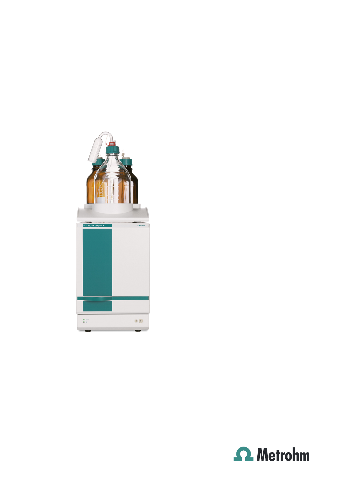
1.1 Instrument description
1 Introduction
1.1 Instrument description
The 844 UV/VIS Compact IC is a PC-controlled instrument for
chromatographic analysis that is available in the six following versions:
• 2.844.0010 UV/VIS Compact IC
• 2.844.0020 UV/VIS Compact IC with post column reactor
• 2.844.0030 UV/VIS Compact IC 844: Steel
• 2.844.0110 UV/VIS Compact IC with column heating
• 2.844.0120 UV/VIS Compact IC with post column reactor
and column heating
• 2.844.0130 UV/VIS Compact IC 844 with column heating:
Steel
All the necessary components for chromatography with UV/VIS
detection are contained in the extremely compact housing of the 844
UV/VIS Compact IC:
• Injection valve – for single injections or for use with a sample
changer, e.g. the 838 Advanced Sample Processor.
• High-pressure pump – extremely low pulsation double-piston
pump with a flow range of 0.2 … 2.5 mL/min and a maximum
pressure of 35 MPa (350 bar).
• Pulsation dampener – the pulsation dampener reliably protects
the columns from damage, even with low-level pressure variations
(not necessairy with versions 2.844.0030 and 2.844.0130).
• Column heating – the perfect insulation of the housing creates
thermally stable conditions for the columns (with Versions
2.844.0110, 2.844.0120 and 2.844.0130).
• Columns – whether anion columns, cation columns or separating
columns for organic acids – they all find space in the column
compartment of the 844 UV/VIS Compact IC.
• Post column reactor – in the post column reactor the eluate from
the column and a reagent delivered by a peristaltic pump are
mixed and transported to the detector. In this way ions that cannot
be detected are converted into (optically) detectable species (with
Versions 2.844.0020 and 2.844.0120).
• UV/VIS detector – for the determination of transitional metals with
post column derivation, chromate, bromate, nitrite and nitrate in
strongly polluted waters, as well as various organic ions.
844 UV/VIS Compact IC / Gebrauchsanweisung 8.844.1051
1
Page 14

Table of contents
The two steel versions 2.844.0030 and 2.844.0130 are used for HPLC
applications. There is an addittional componet of stel versions:.
• Gas-Sensor – the gas-sensor disrupts power supply, whenever
sovent concentration gets too high.
The operation of the 844 UV/VIS Compact IC takes place via a PC
connected to the RS232 interface with the help of the «IC Net» control
and evaluation program. This PC program can be used to create
systems for recording and evaluating chromatograms. Time programs
can also be created in which a large number of instrument functions
can be triggered for each program step. It is also possible to use programmable signals to control external instruments via the remote
interface.
The «IC Net» operating software meets all the requirements you could
place today on a modern integration software: single or multi-point
calibration, internal or external standard, selectable algorithms for nonlinear calibration, various integration modes with integration parameters
and integration events, different methods for peak recognition, peak
editor, free scaling, superimposing several chromatograms, use of
sample tables and batch reprocessing; a powerful and GLP-conform
report generator with output interfaces for monitor, printer and external
databases.
The independent «Autodatabase» PC program supplied can be used to
save and handle results and chromatograms produced by the «IC Net»
program in a database. With «Autodatabase» data can be sorted,
filtered and searched with the help of different criteria. In addition, data
and curves can be printed out according to user-defined report
templates.
The «IC Net» software can be configured and used in order to comply
with the Electronic Records and Signatures Rule, known as 21 CFR
Part 11, established by the U.S. Food and Drug Administration (FDA).
For this purpose the program contains password protection, user administration, electronic signatures, audit trail and administration of methods and results in databases. To use the 21 CFR Part 11 features of
«IC Net» the operating system Windows 2000 or Windows XP with
NTFS file system is required.
Page 15
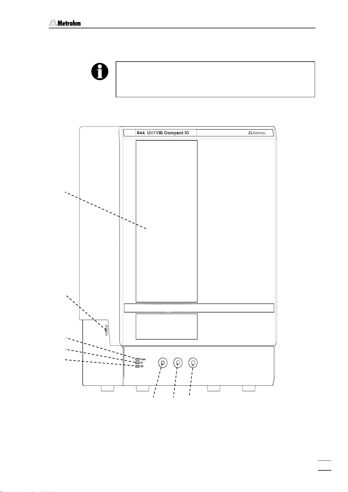
1.2 Parts and controls
8
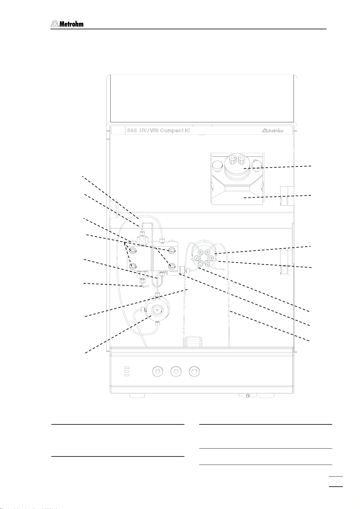
1.2 Parts and controls
In this Section you will find the numbers and designations of the parts
and controls of the 844 UV/VIS Compact IC. The numbering applies
throughout the Instructions for Use, i.e. bold numbers in the text (e.g.
4
) refer to the parts and controls illustrated here.
1.2.1 Front
1
2
3
4
5
6
Figure 1: Front 844 UV/VIS Compact IC
7
844 UV/VIS Compact IC / Gebrauchsanweisung 8.844.1051
3
Page 16

Table of contents
Door to inner compartment
1
Feedthrough
2
for eluent, sample, waste, reagent...
LED "Power"
3
lights up when the instrument is
switched on.
LED "UV"
4
lights up when the UV lamp is on.
LED "VIS"
5
lights up when the VIS lamp is on.
Connection purge valve
6
Connection for 6.2816.020 syringe
7
for aspiration of the sample
Feedthrough
8
for eluent, sample, waste, reagent...
Page 17
1.2 Parts and controls
20 19 14
17
1.2.2 Rear panel
15
16
18
9
10
11
12
13
2
21
22
23
Figure 2: Rear 844 UV/VIS Compact IC
2 Feedthrough
for eluent, sample, waste, reagent...
Lamp cooling housing
9
VIS lamp connection
10
for VIS lamp connection cable
UV lamp connection cable
11
13
UV lamp connection
12
for UV lamp connection cable
VIS lamp connection cable
13
Analog output
14
output for analog signal
Control input
15
11
for control by other instruments
844 UV/VIS Compact IC / Gebrauchsanweisung 8.844.1051
5
Page 18

Table of contents
USB-B connection
16
USB-A connection
17
RS232 interface
18
PC connection
Transport security screws
19
to secure the pump head when the
instrument is transported
Mains switch
20
to switch instrument on and off:
I = ON 0 = OFF
Mains connection plug
21
Mains connection, see Section
Fuse holder
22
Changing the fuses, see Section
Remote interface
23
Remote-I/O lines for connection of
external devices
2.4
2.4
Page 19
1.2 Parts and controls
44
43
51
1.2.3 Interior PEEK versions
42
24
25
26
27
28
29
26
30
31
32
45
44
46
47/48
49
50
34
33
35
36
37
38
39
40
41
Figure 3: Interior PEEK versions
844 UV/VIS Compact IC / Gebrauchsanweisung 8.844.1051
7
Page 20

Table of contents
Connection capillary
24
Connection pump head – purge
valve, fixed mounting
Connection capillary
25
in pump head, fixed mounting
Magnetic mounting rail for co-
26
lumn heating
Pump head (6.2824.100)
27
Fastening screws
28
for pump head
Connection capillary
29
27
from purge valve to Filter unit PEEK.
6.1831.010 PEEK capillary,
length L = 13 cm
Aspirating capillary
30
Connection for 6.1834.010 aspirating
tubing
Connection capillary
31
from purge valve to connection
6
Mounting pin
40
for attaching the tubing cartridges
Aspirating tubing
41
for sample;
PTFE-tubing 6.1803.020
Flow-through cell PEEK
42
6.2839.130
UV/VIS detector
43
Mounting rail
44
for 6.2027.0X0 Column holder, and
6.2057.050 PCR holder
Sample loop
45
PEEK sample loop
Injection valve
46
6.1831.110 Column inlet capillary
47
for column connection without column heating.
6.1831.110 PEEK capillary,
length L = 30 cm
Purge valve
32
Connection capillary to syringe
33
(with manual injection)
6.1803.020 PTFE tubing,
length L = 30 cm
Filter unit PEEK (6.2821.120)
34
Connection capillary
35
from Filter unit PEEK to Pulsation
dampener.
6.1831.010 PEEK capillary,
length L = 13 cm
Pulsation dampener (6.2620.150)
36
Leak detector
37
Inlet capillary for injection valve
38
PEEK capillary 6.1831.010,
length L = 24 cm
6.1831.100 Column inlet capillary
48
for column connection with column
heating.
6.1831.100 PEEK capillary,
length L = 1 m
Peristaltic pump
49
for operating the post column reactor
Holding clamp
50
for locking the tubing cartridge into
place
Pump drive
51
roller head with contact rollers
Connection for drainage tubing
39
for draining off escaped liquid
Page 21
1.2 Parts and controls
61 41
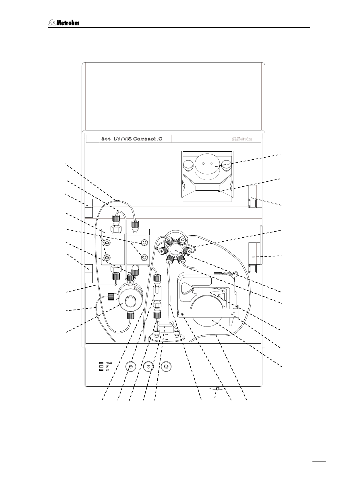
1.2.4 Interior Steel versions
62
52
53
54
55
56
30
33
57
60
63
59
58
Figure 4: Interior Steel Versions
Steel connection capillary
52
Connection steel pump head – steel
Steel connection capillary
53
in pump head, fixed mounting
purge valve, fixed mounting
Steel pump head 6.2824.040
54
844 UV/VIS Compact IC / Gebrauchsanweisung 8.844.1051
9
Page 22

Table of contents
Steel fastening screws
55
for steel pump head
Steel connection capillary
56
54
Steel capillary 6.2620.020 from steel
purge valve to steel filter unit.
Steel purge valve
57
Steel filter unit 6.2620.180
58
Steel connection capillary
59
Steel capillary 6.2620.020 from Steel
filter unit to steel injection valve.
Steel Injection valve
60
Steel UV/VIS detector
61
Steel flow-through cell 6.2839.100
62
Steel sample loop 6.2620.110
63
Page 23

1.3 Information on the Instructions for Use
1.3 Information on the Instructions for Use
Please read through these Instructions for Use carefully before you put
the 844 UV/VIS Compact IC into operation. The Instructions for Use
contain information and warnings to which the user must pay attention
in order to assure safe operation of the instrument.
1.3.1 Organization
These Instructions for Use 8.844.1053 for the 844 UV/VIS Compact
IC provide a comprehensive overview of installation, startup procedure,
operation, fault rectification and technical specifications of this
instrument. The Instructions for Use are organized as follows:
Sect.
1 Introduction
General description of instrument, parts and controls and
safety notes
2 Installation
Sect.
Installation of instrument, accessories, external devices
and software
3 Operation
Sect.
Introduction to the operation
4 Notes - Maintenance - Faults
Sect.
Notes on ion chromatography, maintenance, fault
rectification, diagnostic tests, validation
Sect.
5 Appendix
Technical data, standard equipment, options, warranty,
declarations of conformity, index
To find the required information on the instruments, use either the
Table of contents or the Index at the back.
As a supplement to the Instructions for Use, the Metrohm Monograph
8.792.5003 "Practical Ion Chromatography" is also supplied. This
provides an introduction to the theoretical fundamentals and general
information about determinations.
844 UV/VIS Compact IC / Gebrauchsanweisung 8.844.1051
11
Page 24
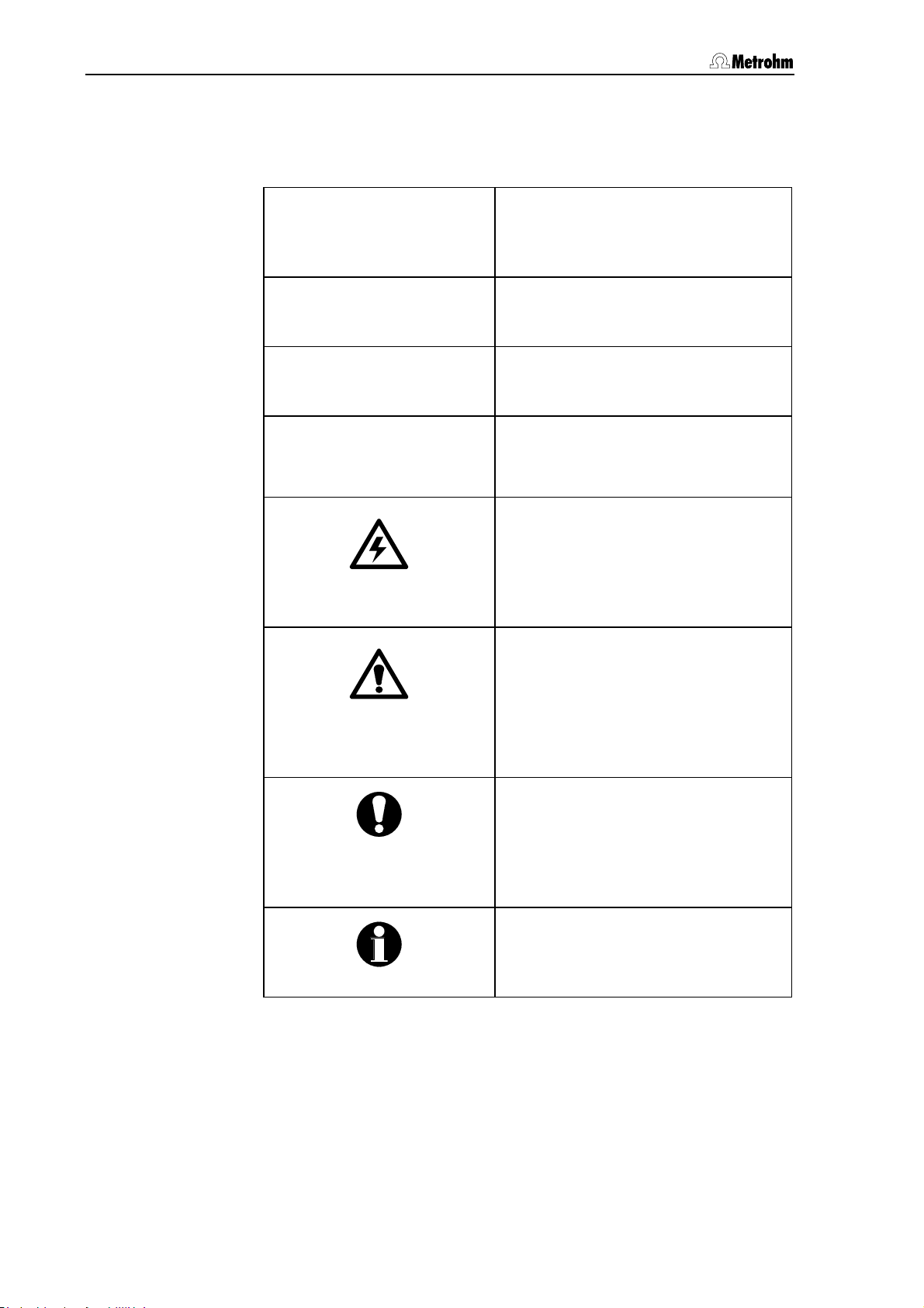
Table of contents
1.3.2 Notation and pictograms
The following notations and pictograms (symbols) are used in these
Instructions for Use:
Fill Menu item, parameter or entry
value
in the software
SYSTEM STATE Program window
in the software
<OK> Button
in the software
26
Part or control of 844
Hazard
This symbol draws attention to a
possible danger to life or of injury if
the associated directions are not
followed correctly.
Warning
This symbol draws attention to
possible damage to instruments or
instrument parts if the associated
directions are not followed
correctly.
Caution
This symbol marks important
information. First read the
associated directions before you
continue.
Comment
This symbol marks additional
information and tips.
Page 25
1.4 Safety notes
1.4 Safety notes
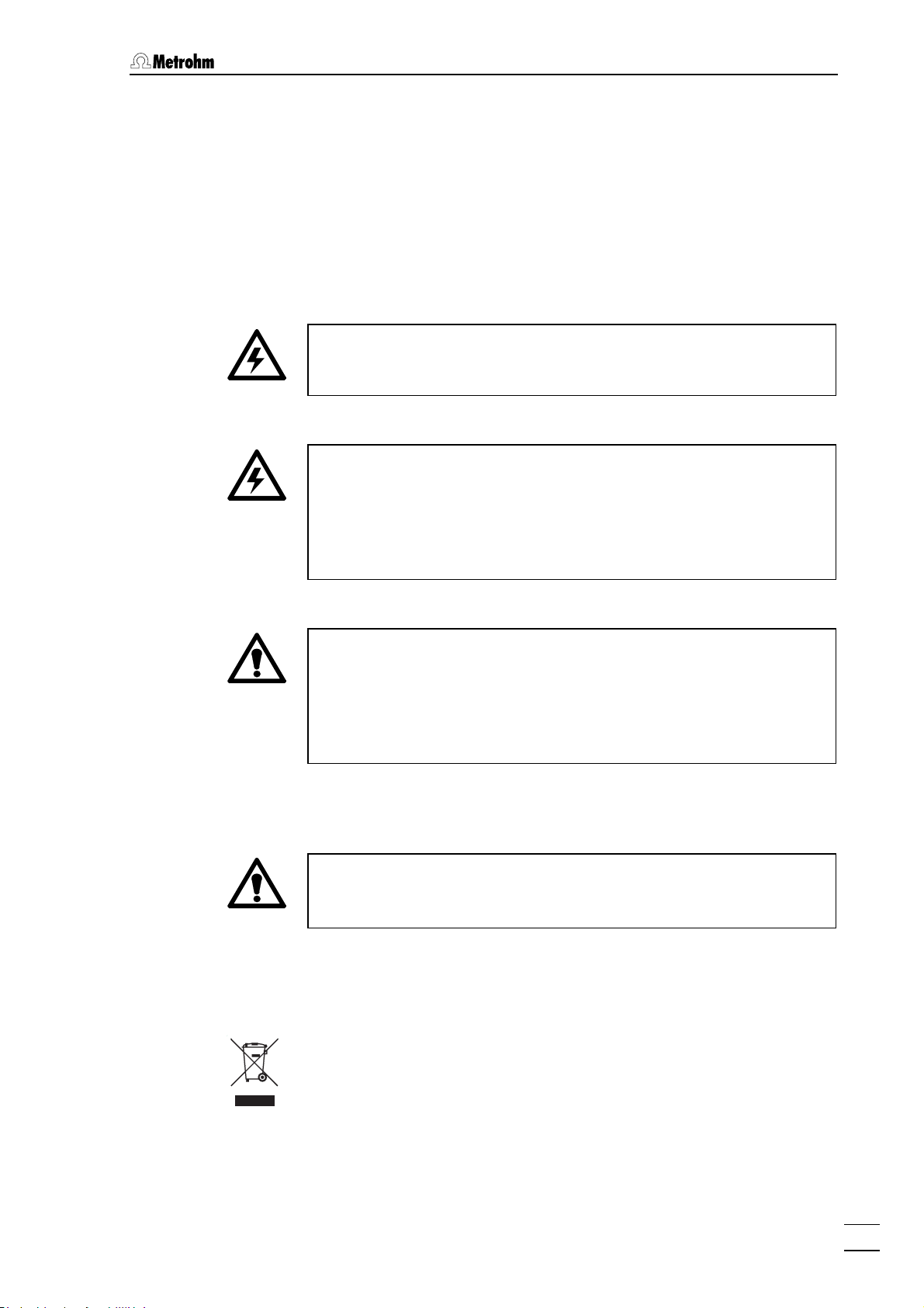
1.4.1 Electrical safety
While electrical safety in the handling of the 844 UV/VIS Compact IC is
assured in the context of the specifications EN / IEC 61010-1
(protection class
should be noted:
• Mains connection
Setting of the mains voltage, checking the mains fuse and the
mains connection must be effected in accordance with the
instructions in Section
• Opening the 844 UV/VIS Compact IC
If the 844 UV/VIS Compact IC is connected to the power supply, the
instrument must not be opened nor must parts be removed from it,
otherwise there is a danger of coming into contact with components
which are live. Therefore always disconnect the instrument from all
voltage sources before you open it and ensure that the mains cable
is disconnected from mains connection
I, degree of protection IP40), the following points
2.4.
21 !
• Protection against static charges
Electronic components are sensitive to static charging and can be
destroyed by discharges. Before you touch any of the components
inside the 844 UV/VIS Compact IC, you should ground yourself and
any tools you are using by touching a grounded object (e.g. housing
of the instrument or a radiator) to eliminate any static charges which
exist.
1.4.2 General precautionary rules
• Handling of solvents
Check all lines of the IC system periodically for possible leaks. Follow
the relevant instructions regarding the handling of flammable and/or
toxic solvents and their disposal.
1.4.3 Recycling and disposal
This product is covered by European Directive 2002/96/EC, WEEE –
Waste from Electrical and Electronic Equipment.
The correct disposal of your old equipment will help to prevent negative
effects on the environment and public health.
More details about the disposal of your old equipment can be obtained
from your local authorities, from waste disposal companies or from your
local dealer.
844 UV/VIS Compact IC / Gebrauchsanweisung 8.844.1051
13
Page 26
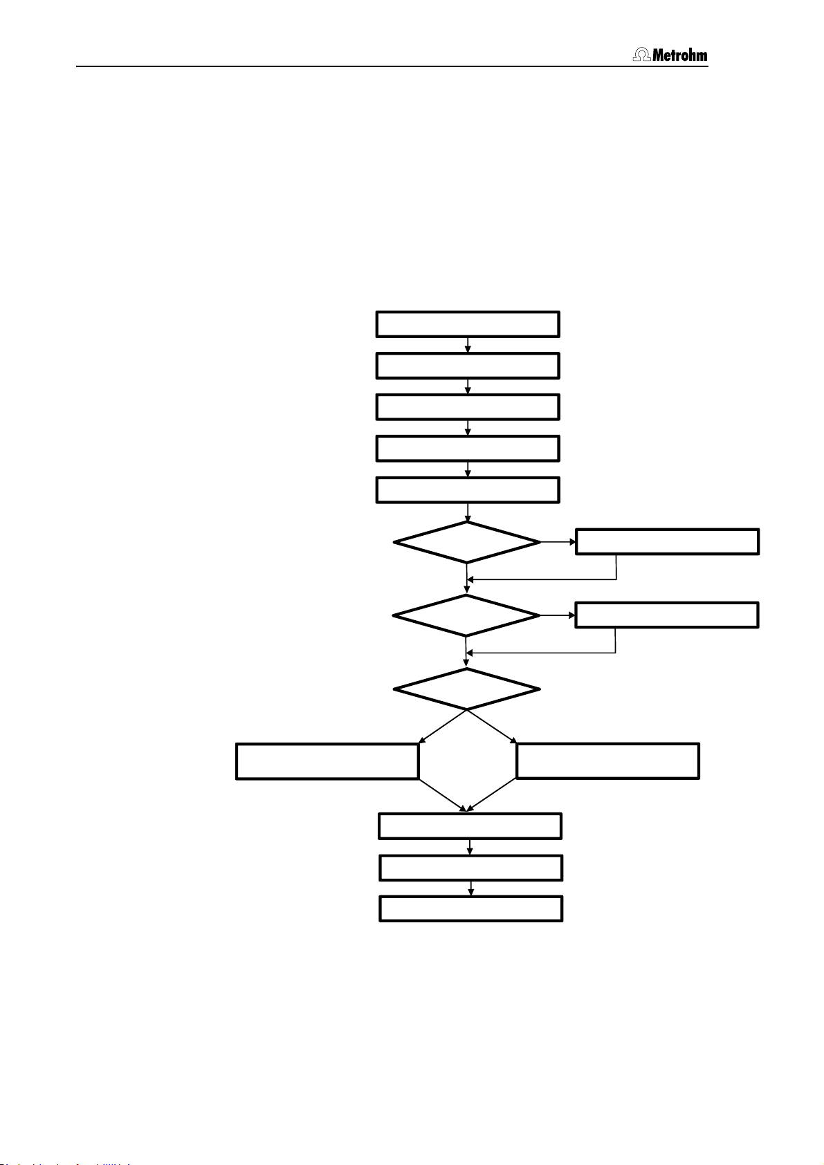
Table of contents
2 Installation
2.1 Overview
2.1.1 Flow chart
The following flow chart provides an overview of all installation work.
You will find more detailed information in the relevant Sections.
Setting up sect. 2.2
Installing accessories sect. 2.3
Mains connection sect. 2.4
Connectting PC sect. 2.5
Connecting column
Connecting high press. pump sect. 2.6
Post column reactor?
No
Precolumn?
No
Column heating?
No
sect. 2.8.3
Connecting of the detector sect. 2.9
Conditioning sect. 2.10
Yes
Yes
Install post column reactor
Yes
Connecting precolumn sect. 2.8.1
Connecting column and
column heating
sect. 2.7
sect. 2.8.4
Connecting external devices sect. 2.11
Page 27
2.1 Overview
35 36 38 33 41
45
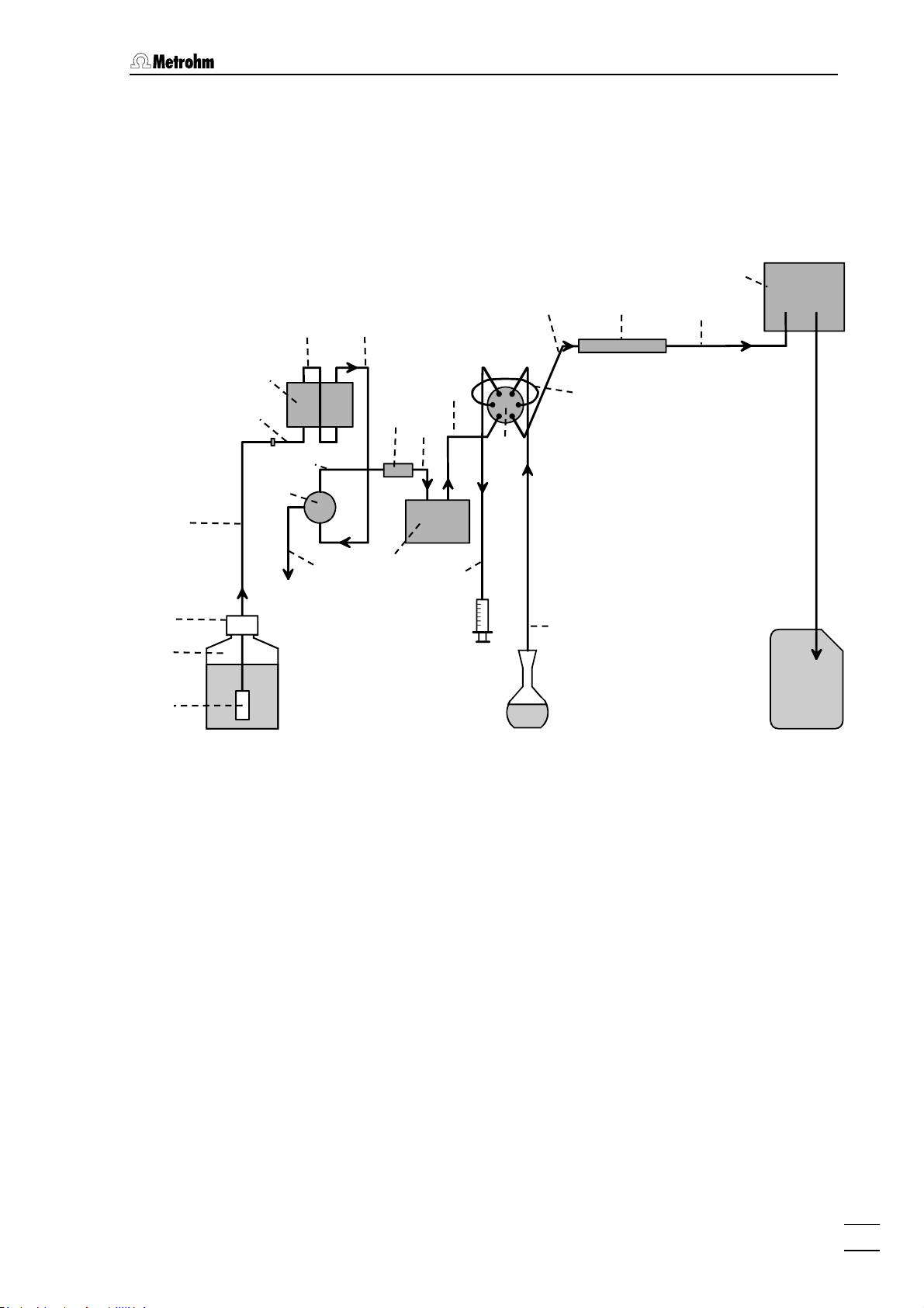
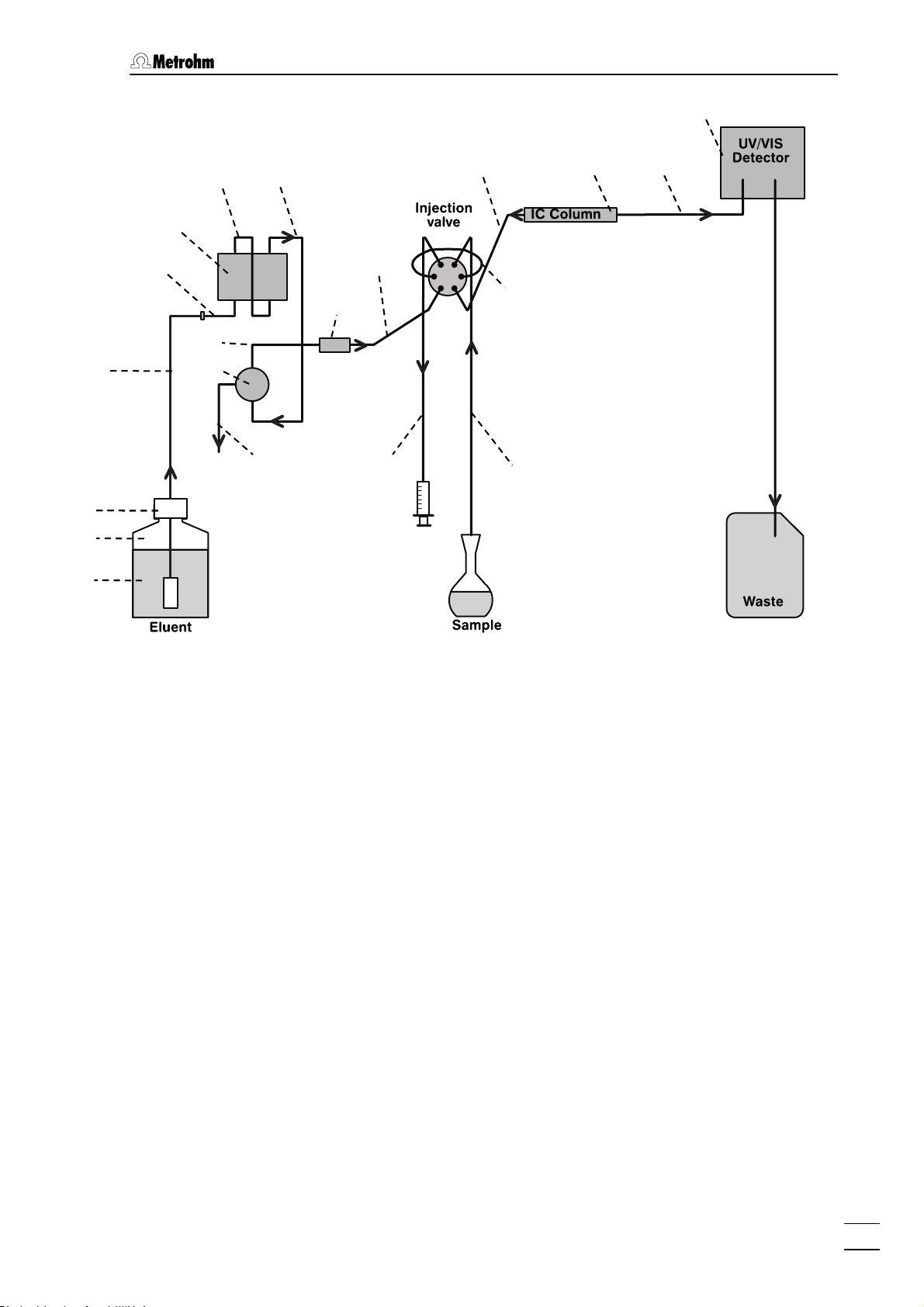
2.1.2 Connections in the 844 UV/VIS Compact IC
The following illustrations show the internal connections in the 844
UV/VIS Compact IC in schematic form. The meanings of the various
numbered components are given in the detailed illustrations and
descriptions in Sections
2.2 – 2.11.
25
24
Injection valve
47
113
IC Column
43
112
UV/VIS
Detector
27
30
29
34
46
32
82
31
85
86
87
Eluent
Sample
Waste
Figure 5: Connecting diagram for 844 UV/VIS Compact IC 2.844.0010
844 UV/VIS Compact IC / Gebrauchsanweisung 8.844.1051
15
Page 28
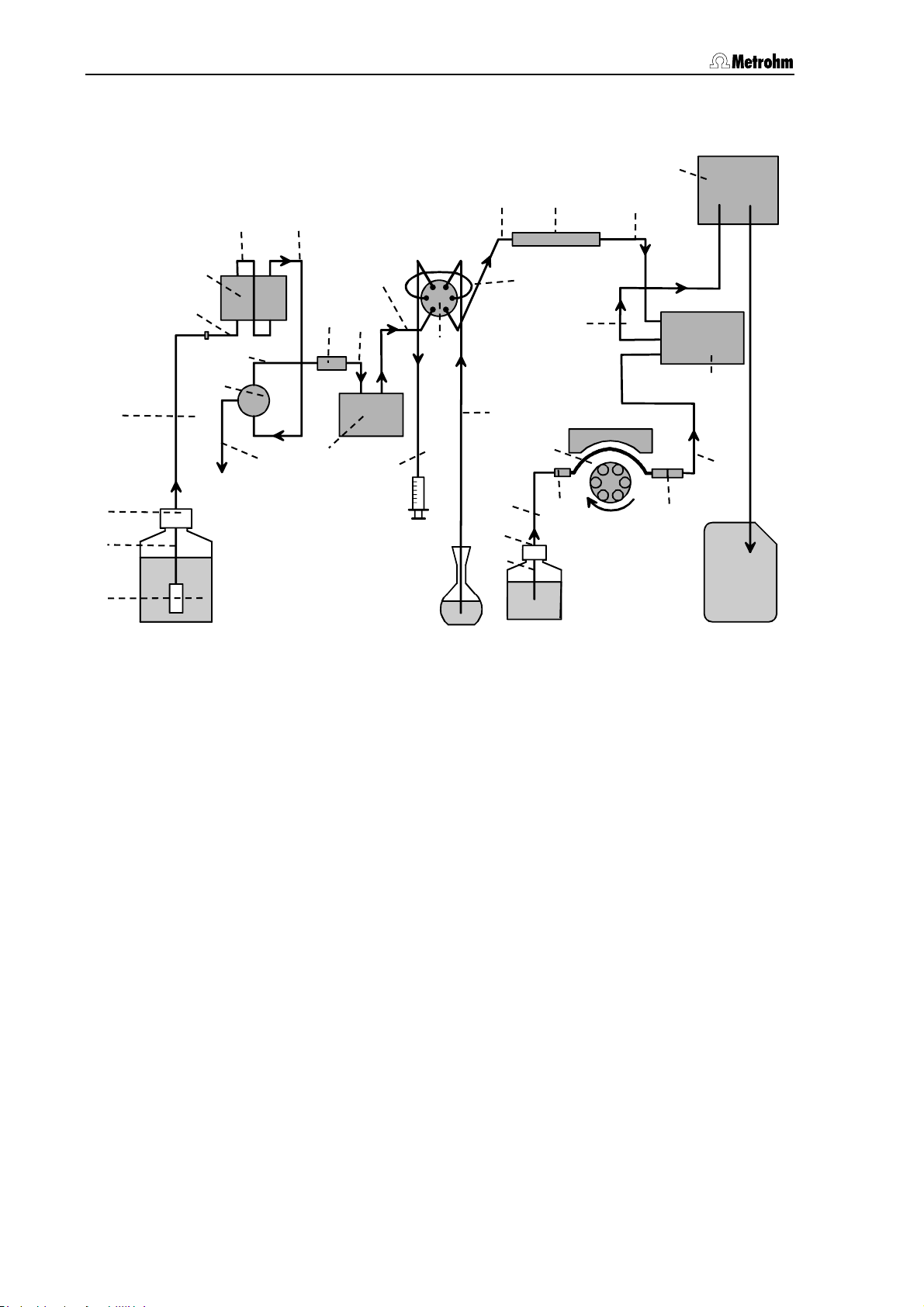
Table of contents
47
94 93
41
85
86
87
82
27
30
Eluent
32
25
29
31
24
34
36
35
33
Injection
valve
46
Sample
92
108
109
47
IC Column
45
Reagent
113
103
43
107
99
UV/VIS
Detector
Post column
reactor
101
100
Waste
Figure 6: Connecting diagram for 844 UV/VIS Compact IC 2.844.0020 with
Post column reactor
Page 29
2.1 Overview
63
61
85
Fehl
86
87
82
30
54
53
56
57
52
31
59
58
33
110 113 112
41
Figure 7: Connecting diagram for 844 UV/VIS Compact IC 2.844.0030
844 UV/VIS Compact IC / Gebrauchsanweisung 8.844.1051
17
Page 30
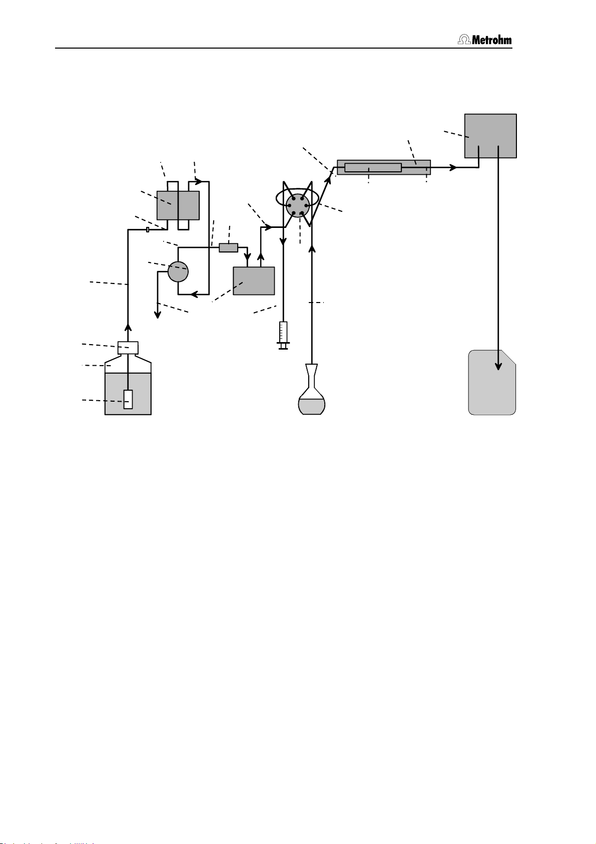
Table of contents
46 45
85
86
87
82
27
30
25
24
34
35
47
48
Injection
valve
127
Column heating
IC Column
113
43
122
UV/VIS
Detector
29
32
41
31
Eluent
36
33
Waste
Sample
Figure 8: Connecting diagram for 844 UV/VIS Compact IC 2.844.0110 with
Column heating
Page 31

2.1 Overview
35 36 33 46 48
85
86
87
82
43
UV/VIS
Detector
127
Column heating
IC Column
113
45
105
104
Post column
reactor
27
30
25
24
Injection
valve
47
34
29
32
31
41
94
101
107
92
108
93
99
109
Waste
Eluent
Sample
Reagent
Figure 9: Connecting diagram for 844 UV/VIS Compact IC 2.844.0120 with
Post column reactor and Column heating
844 UV/VIS Compact IC / Gebrauchsanweisung 8.844.1051
19
Page 32

Table of contents
63
61
85
Fehl
86
87
82
30
54
53
56
57
52
31
58
59
33
110
Column heating
Column heating
IC Column
IC Column
41
113
112
127
Eluent
Sample
Figure 10: Connecting diagram for 844 UV/VIS Compact IC
2.844.0130 with Column heating
2.2 Setting up the instrument
2.2.1 Packaging
The 844 UV/VIS Compact IC is supplied together with the separately
packed accessories in special packagings containing shock-absorbing
foam linings designed to provide excellent protection. The instrument
itself is packed in an evacuated polyethylene bag to prevent the ingress
of dust. Please store all these special packagings as only they assure
transport of the instrument free from damage.
2.2.2 Check
After receipt, immediately check whether the shipment is complete and
has arrived without damage (compare with delivery note and list of
accessories in Section
structions in Section
5.2). In the case of transport damage, see in-
5.4.1 "Warranty".
Page 33

2.3 Attaching the accessories
2.2.3 Location
Position the instrument in the laboratory at a location convenient for
operation, free from vibrations and protected against a corrosive atmosphere and contamination by chemicals.
To avoid disturbing temperature influences on the insulated column
compartment, the instrument must be protected against direct sunlight.
2.3 Attaching the accessories
2.3.1 Connecting the syringe and aspirating tubing
For the manual filling of sample loop 45/63 mounted at the injection
valve the 6.2816.020 Syringe and PTFE aspirating tubing
connected to the injection valve) are required. These accessories are
attached and adjusted as follows:
1 Connecting the syringe
• Remove the plastic stopper from connection 7 on the front
panel of the 844 UV/VIS Compact IC.
• Push 6.2816.020 Syringe(without needle) into connection
until it reaches the stop.
2 Pull out the aspirating tubing
• Pull the PTFE aspirating tubing 41 connected to injection
46/61 through feedthrough 7 by hand as far as
valve
required.
41 (already
7
2.3.2 Connecting the drainage tubing for the inner compartment
The 844 UV/VIS Compact IC has a connection 39 on its front panel to
allow any escaped liquid to be drained off from the inner compartment.
A piece of drainage tubing can be attached to it. Proceed as follows:
1 Connecting the drainage tubing
• Push 6.1816.060 Silicone tubing onto the connection nipple
at the bottom right-hand side of the front panel.
2 Lead the drainage tubing into a drain
• Lead the other end of the drainage tubing into a drain and fix
it in position.
2.3.3 Connecting PEEK capillaries
With the versions 2.844.0010, 2.844.0020, 2.844.0110 and 2.844.0120,
the connections from the high-pressure pump to the detector consist of
6.1831.010 PEEK capillaries (i.d. = 0.25 mm, o.d. = 1/16"), which are
connected with either 6.2744.010 PEEK compression fitting (long) or
844 UV/VIS Compact IC / Gebrauchsanweisung 8.844.1051
21
Page 34

Table of contents
6.2744.070 PEEK compression fitting (short). The connection pieces
are mounted on the capillaries as follows:
PEEK capillaries that are to be provided with new connection pieces
must have a perfectly flat cut surface. This is best achieved by using
the 6.2621.080 Capillary cutter available as an option.
1 Mounting the compression fitting
• At the end of capillary Fehler! Verweisquelle konnte nicht
gefunden werden. that is to be attached push either a
compression fitting Fehler! Verweisquelle konnte nicht
gefunden werden. (6.2744.010) or compression fitting Fehler!
Verweisquelle konnte nicht gefunden werden. (6.2744.070)
over the capillary as shown in Fehler! Verweisquelle konnte
nicht gefunden werden..
2 Lead the capillary into the connection
• Push the capillary end into the corresponding connection
until it reaches the stop (in order to avoid dead volume).
3 Tighten up compression fitting
• Tighten up compression fitting Fehler! Verweisquelle konnte
nicht gefunden werden. or Fehler! Verweisquelle konnte nicht
gefunden werden. by hand (do not use any tools).
64
66
65
Figure 11: Connectors for PEEK capillaries
2.3.4 Connecting Steel capillaries
With the versions 2.844.0030 and 2.844.0130, the connections from
the high-pressure pump to the detector consist of 6.2620.020 Steel
capillaries (i.d. = 0.25 mm, e.d. =
connected with the steel connectors 6.2620.010 Ferrule and
6.2620.000 Pressure screw available as an option. The connection
pieces are mounted on the capillaries as follows:
Compression fitting
64
(6.2744.010)
Compression fitting
65
(6.2744.070)
Capillary 6.1831.XXX PEEK
66
capillary
1
/16", length = 3 m), which are
Steel capillaries fitted with new connectors must have a perfectly flat
cut surface. This is best achieved by using the 6.2621.040 Capillary
tubing cutter available as an option.
Page 35

2.3 Attaching the accessories
70
1 Mount connectors
Slide a pressure screw 69 (6.2620.000) and a ferrule 68
(6.2620.010) over the end of the capillary
2 Insert capillary in connection
Push capillary end into the corresponding connection as far as it
will go (to avoid dead volume).
3 Tighten pressure screw
Tighten pressure screw 69 with the open-end spanner 1/4"
(6.2621.010) supplied.
70 to be fastened.
67
68
Figure 11: Connectors for Steel capillaries
69
70
2.3.5 Filter unit PEEK
With the versions 2.844.0010, 2.844.0020, 2.844.0110 and
2.844.0120, there is a 6.2821.120 PEEK filter unit mounted between
the high-pressure pump and injection valve
against particles.
PEEK filter unit
New filters
6.2821.130 (10 pieces).
34 consists of housing 73, filter screw 71 and filter 72.
72 are available as an option under ordering number
Ferrule (6.2620.010)
67
used in pre-installed
components only
Ferrule (6.2620.270)
68
Pressure screw (6.2620.000)
69
Capillary
6.2620.020 Steel capillary
46. It protects the valve
When connecting the filter unit please note the flow direction arrow
printed on the housing.
844 UV/VIS Compact IC / Gebrauchsanweisung 8.844.1051
23
Page 36

Table of contents
71 72 73
34
35
64
Figure 12: 6.2821.120 Filter unit PEEK
29 Connection capillary
6.1831.010 PEEK capillary,
length L = 13 cm
34 Filter unit PEEK (6.2821.120)
35 Connection capillary
6.1831.010 PEEK capillary,
length L = 13 cm
2.3.6 Filter unit Steel
With the versions 2.844.0030 and 2.844.0130, there is a Steel filter
unit 6.2620.180 mounted between the high-pressure pump and
injection valve. It protects the valve against particles.
The Steel filter unit consists of housing
New filters
6.2821.130 (10 pieces).
29
Filter screw of filter unit
71
64
Part of 6.2821.120 Filter unit
Filter 6.2821.130
72
Part of 6.2821.120 Filter unit
Filter housing of filter unit
73
Part of 6.2821.120 Filter unit
78, filter screw 76 and filter 77.
77 are available as an option under ordering number
When connecting the filter unit please note the flow direction arrow
printed on the housing.
75
74
69
67
78
77
76
67
69
79
Figure 13: 6.2620.180 Filter unit Steel
Page 37

2.4 Mains connection
Steel connection capillary
74
6.2620.020
from steel purge valve to steel filter
unit.
Steel filter unit 6.2620.180
75
Filter screw of filter unit
76
Part of 6.2620.180 Filter unit
Filter 6.2620.190
77
Part of 6.2620.180 Filter unit
2.4 Mains connection
Follow the instructions below for connecting to the power supply. If the
instrument is operated with a mains voltage set wrongly and/or wrong
mains fuse, there is a danger of fire!
Filter housing of filter unit
78
Part of 6.2620.180 Filter unit
Steel connection capillary
79
6.2620.020
from steel filter unit to steel pulsation
dampener
2.4.1 Setting the mains voltage
Before switching on the 844 UV/VIS Compact IC for the first time, check
that the mains voltage set on the instrument matches the local mains
voltage. If this is not
instrument as follows:
1 Disconnect mains cable
Disconnect mains cable from mains connection plug 21 of the
844 UV/VIS Compact IC.
2 Disconnect mains cable
Using a screwdriver, loosen fuse holder 22 below the mains
connection plug
3 Check and change fuse if necessary
Carefully take the fuse installed for the desired mains voltage out
of fuse holder
fuse in the fuse holder is marked by the white arrow imprinted
next to the mains voltage range):
100…120 V 1.6 A (slow-blow)
the case, you must reset the mains voltage on the
21 and take out completely.
22 and check its specifications (the position of the
220…240 V 0.8 A (slow-blow)
4 Insert fuse
Change fuse if necessary and reinsert in fuse holder 22.
5 Install fuse holder
Depending on the desired mains voltage, insert fuse holder 22
in the 844 UV/VIS Compact IC so that the corresponding mains
844 UV/VIS Compact IC / Gebrauchsanweisung 8.844.1051
25
Page 38

Table of contents
V
voltage range can be read normally and the adjacent white
arrow points to the white bar imprinted below the fuse holder.
220 – 240 V
20
21
-
100
120 V
22
220 - 240 V
Figure 14: Setting the mains voltage
2.4.2 Fuses
100 – 120
20 Mains switch
to switch instrument on and off:
I = ON 0 = OFF
21 Mains connection plug
2.4.3
100 - 120 V
-
220
240 V
Mains connection, see Section
22 Fuse holder
One of the two fuses 1.6 A/slow-blow for 100…120 V or 0.8 A/slow-blow
for 220…240 V is installed in fuse holder
22 of the 844 UV/VIS Compact
IC as standard.
Ensure that the instrument is never put into operation with fuses of
another type, otherwise there is danger of fire!
When checking or changing fuses proceed as described in Section
2.4.1.
2.4.3 Mains cable and mains connection
Mains cable
The instrument is supplied with one of three mains cables
• 6.2122.020 with plug SEV 12 (Switzerland, …)
• 6.2122.040 with plug CEE(7), VII (Germany, …)
• 6.2133.070 with plug NEMA 5-15 (USA, …)
which are three-cored and fitted with a plug with a grounding pin. If a
different plug has to be fitted, the yellow/green lead (IEC standard)
must be connected to protective ground (protection class 1).
Any break in the grounding inside or outside the instrument can make
it a hazard!
Mains connection
Plug the mains cable into mains connection plug
Compact IC.
21 of the 844 UV/VIS
Page 39

2.5 Connection to PC
2.4.4 On/off switching of the instrument
The 844 UV/VIS Compact IC is switched on and off using mains switch
20. When the instrument is switched on, the mains pilot lamp 3 lights
up.
2.5 Connection to PC
2.5.1 Connecting cable
Always switch off 844 UV/VIS Compact IC and PC before you connect
the two instruments with the 6.2134.100 Cable.
Connect the RS232 interface
serial COM port at the PC using the 6.2134.100 Cable (9-pin/9-pin). If
only a 25-pin COM interface is available on the PC then the 6.2125.110
Adapter cable or a commercially available adapter must be used.
18 at the 844 UV/VIS Compact IC to a
2.5.2 Software installation
The PC program «IC Net» (from Version 2.3 SR2) is required for operating the 844 UV/VIS Compact IC; this is included in the standard
equipment on CD 6.6034.033. This program runs under the operating
systems Windows 2000 and Windows XP and is installed as follows:
1 Install program
• Insert the installation CD 6.6034.033 into your CD-ROM drive.
• If the autorun option for the CD drive is disabled, select
<Start> and Run. Browse for the Setup.exe file on the
installation CD and click on
• Click "
2 Files
• The installation program copies the files from the
installation CD into the folder entered by you and generates the
subfolders IC Net and Autodatabase. The following subfolders are
also generated, among others:
IC Net" and follow the on-screen prompts of the Setup
program (see Instructions for Use «IC Net», Section 1.5 for a
more detailed description).
Data Folder for storage of chromatogram files
Devices Folder for storage of device files (*.dev)
Excelreport Folder for Excel reports (*.xls)
Methods Folder for storage of method files (*.mtw)
Reports Folder for storage of report files (*.txt)
Systems Folder with subfolders with system files
<OK>.
*.chw) and batch reprocessing files (*.bar)
(
and graphic files (
(
*.smt) and sample queue files (*.que).
*.wmf)
844 UV/VIS Compact IC / Gebrauchsanweisung 8.844.1051
27
Page 40

Table of contents
The installed files (incl. system and method files) are generally not
write-protected. To prevent these files from being deleted by mistake,
switch on the write-protection or make a backup copy in another
directory.
2.5.3 First Login
Starting and closing of the Software is described in the provided
Software Instructions for Use «IC Net», Section 2.
The
Add User window (see below) opens the first time you launch the
program after installing the software and a user with Administrator
access rights is created.
2.5.4 Create a system
Create in «IC Net» a system to control the 844 UV/VIS Compact IC.
Proceed as described in Section 4.4.1 of the Software Instructions for
Use «IC Net»: System wizard. Add your version of the 844 UV/VIS
Compact IC (they are listed under "Metrohm Detectors") to the system,
and choose the port to which it is connected.
Page 41

2.6 High-pressure pump
2.6 High-pressure pump
In order to avoid damage to the pump it must never be operated dry.
Each time that the pump is switched on always first check that the
eluent supply has been connected up correctly and that sufficient
eluent is present in the eluent bottle.
2.6.1 Removing the transport security screws
In order to prevent the pump drive from being damaged during
transport the pump head is fitted with three transport security screws
19. These transport security screws must be removed before the highpressure pump is started up. Also remove the red sticker attached to
the pump head
In order to avoid damage to the pump head these three security
screws should be attached to the pump head each time that the 844
UV/VIS Compact IC is to be transported.
27/54.
2.6.2 Installing the pulsation dampener
With the PEEK versions 2.844.0010, 2.844.0020, 2.844.0110 and
2.844.0120, the 6.2620.150 Pulsation dampener MF has to be
installed between the high-pressure pump and the injection valve of the
844 UV/VIS Compact IC, to protect the column material against
pressure drops caused by the injection valve. Proceed as follows:
1 Install pulsation dampener
• Position the pulsation dampener 36 in the interior of the Com-
pact IC on the base.
2 Connection to the pump
• Unscrew PEEK capillary 35 of coupling and attach it to
connection
3 Connection to injection valve
• Unscrew PEEK capillary 38 of coupling and attach it to
connection
The pulsation dampener is filled with isopropanol and must be rinsed
with eluent before connection to a separating column (see Section
2.6.4).
80 of the pulsation dampener 36.
81 of the pulsation dampener 36.
The 6.2620.150 Pulsation dampener can be operated in both
directions.
The two steel versions 2.844.0030 and 2.844.0130 are operated
without Pulsation dampener.
844 UV/VIS Compact IC / Gebrauchsanweisung 8.844.1051
29
Page 42

Table of contents
38
46
35
29
32
34
Figure 15: Connection of the pulsation dampener
29 Connection capillary
6.1831.010 PEEK capillary,
length L = 13 cm
32 Purge valve
34 Filter unit PEEK (6.2821.120)
35 Connection capillary
from Filter unit PEEK to Pulsation
dampener.
6.1831.010 PEEK capillary,
length L = 13 cm
36 Pulsation dampener (6.2620.150)
80 81
36
38 Inlet capillary for injection valve
PEEK capillary 6.1831.010,
length L = 24 cm
46 Injection valve
Connection to purge valve
80
Connection to injection valve
81
Page 43

2.6 High-pressure pump
2.6.3 Connecting the eluent bottle
The eluent supply line from the storage bottle to the high-pressure
pump is connected as follows:
Only degassed (with N
, He or vacuum) and microfiltered (0.45 μm
2
filter) eluents should be used!
The 6.1608.070 Eluent bottle (2 L) supplied is not suitable for vacu-
um degassing. Use a pressure-resistant container for this.
Care must be taken that the eluent used is freely miscible with any
solvent remaining in the pump head (the pump head leaves the
factory filled with either isopropanol or methanol/water). If this is not
the case then the pump must first be rinsed with a solvent which is
miscible with both the previous eluent and the following eluent (e.g.
acetone).
1 Prepare eluent bottle
• Prepare, microfilter (0.45 μm microfilter) and degas (with N2,
He, or vacuum) the suitable eluent for the required
application and separating column.
• Fill eluent into eluent vessel
86(clear glass, 2 L).
2 Install bottle attachment
• Firmly screw threaded stopper 84 (6.1446.040; part of
6.1602.160) into the smaller threaded opening (M6) of bottle
attachment
• Firmly screw aspirating filter
• Pull the other end of aspirating tubing
threaded opening (M8) of bottle attachment
85 (6.1602.105; part of 6.1602.160).
87 onto aspirating tubing 82.
82. through the larger
85 from below.
• Push O-ring (E.301.0021; part of 6.1602.160) over the free
end of aspirating tubing
attachment
85.
• Push tubing nipple
the free end of aspirating tubing
red towards bottle attachment
larger opening of bottle attachment
• Insert aspirating tubing
82. and move it towards bottle
83 (4.420.4300; part of 6.1602.160) over
82., move it as far as requi-
85 and screw it loosely in the
85.
82. with screwed-on aspirating filter
87 into eluent bottle 86 and screw bottle attachment 85 onto
eluent bottle
• Pull aspirating tubing
86.
82. so far through the opening of tubing
nipple 83 that aspirating filter 87 is touching the bottom of
eluent bottle
• Fix aspirating tubing
nipple
86.
82. in place by screwing shut tubing
83.
844 UV/VIS Compact IC / Gebrauchsanweisung 8.844.1051
31
Page 44

Table of contents
84 85 86
3 Mount CO2 absorber tube
• First place a piece of cotton wool 89 followed by CO2
absorber
6839.1000) in the large opening of absorber tube
88 (e.g. Merck soda lime pellets with indicator, no.
91 and then
close it with the plastic lid.
• Fasten absorber tube
of SGJ clip
90.
91 to bottle attachment 85 with the aid
4 Connect aspirating tubing to pump
• Lead the free end of aspirating tubing 82. through opening 2
into the inner compartment of the 844 UV/VIS Compact IC.
• Pull aspirating tubing
82 sufficiently far into the interior of the
844 UV/VIS Compact IC, cut off to the required length and
push at least 5 mm of it onto aspirating capillary
30 of the
high-pressure pump (it may be necessary to use emery
paper).
• If necessary, fix aspirating tubing
82 in the required position
in the interior with the aid of the Y.107.0150 self-adhesive
strap.
Aspirating tubing (6.1834.010)
82
91
Tubing nipple (4.420.4300; M8)
83
with E.301.0021 O-ring
Threaded stopper (6.1446.040; M6)
84
90
82
83
89
Bottle attachment (6.1602.105)
85
88
Eluent bottle (6.1608.070)
86
Aspirating filter (6.2821.090)
87
CO2 absorber
88
Cotton wool
89
87
SGJ clip (6.2023.020)
90
Absorber tube (6.1609.000)
91
Figure 16: Connection of eluent bottle
2.6.4 Deaerating the pump and rinsing the pulsation dampener
The first time that it is started up the high-pressure pump must be deaerated. Proceed as follows:
1 Prepare for deaeration
• Open the rotary knob on purge valve 32 by approx. ½ turn in
the counterclockwise direction.
• Remove the plastic stopper from connection
6 on the front
panel of 844 UV/VIS Compact IC.
• Push 6.2816.020 Syringe (without needle) into connection
6
until the stop is reached.
Page 45

2.6 High-pressure pump
2 Open and connect system
• Start the «IC Net» PC program, if it has not already been
started (see Section
• Select
File / Open / System in the main window. Select the
system created in Section
2.5.3).
2.5.4, and click on <Open>.
• Select the
Connect to workplace item of the Control menu in this
window.
3 Set flow rate to 2 mL/min
• Double-click the 844 icon in the system window to open the
window for manual control of the 844 UV/VIS Compact IC
(see below).
• Set the flow rate to
• Click to
<Set> to send this value to the 844 UV/VIS Compact
2 mL/min in the Flow field.
IC.
844 UV/VIS Compact IC / Gebrauchsanweisung 8.844.1051
33
Page 46

Table of contents
4 Deaerate pump
• Make sure that the aspirating tubing 82 for the high-pressure
pump has been immersed into the eluent.
• Click the
<On> button for IC pump to switch on the high-pres-
sure pump.
• Use the syringe inserted into connection
6 to aspirate air until
eluent flows bubble-free into the syringe.
• Click the
<Off> button for IC pump to switch off the high-pres-
sure pump.
• Close the rotary knob on purge valve
32 by turning it in a
clockwise direction.
• Remove the syringe from connection
6.
5 Rinse pulsation dampener
• Place a beaker beneath the column connection capillary 47.
• Click the
pressure pump and rinse the pulsation dampener
<On> button for IC pump to switch on the high-
36 filled
with isopropanol for approx. 10 min with eluent.
• Click the
<Off> button for IC pump to switch off the high-pres-
sure pump.
6 Reduce flow rate
• Reset the original flow rate under Flow (e.g. 0.5 mL/min).
• Click
<Set> to send this value to the 844 UV/VIS Compact IC.
• Click <Save> to save the values.
2.7 Post column reactor
This chapter covers the two versions 2.844.0020 and
2.844.0120.
With versions 2.844.0010, 2.844.0030, 2.844.0110 or
2.844.0130 you can skip this chapter and go directly to Section
2.8.
Instrument versions 2.844.0020 and 2.844.0120 of the 844 UV/VIS
Compact IC contain the 6.2836.000 Post column reactor (see
Instructions for Use 8.108.1031 Post column reactor).
2.7.1 Preparing the peristaltic pump
Before it is started up, the accessories must be mounted on the
peristaltic pump built into the 844 UV/VIS Compact IC Proceed as
follows:
1 Remove the tubing cartridge
• Loosen tubing cartridge 96 mounted above pump drive 51 by
pressing down snap-action lever 98 from holder clip 50 and
remove it from mounting pin
40.
Page 47

2.7 Post column reactor
95
2 Attach coupling 93
• At the left-hand end of pump tubing 94 6.1826.320 push on a
coupling
93 6.2744.030. Slightly moistening the Tipp of the
coupling makes this easier.
• Fix "Aspirating tubing for reagent"
compression fitting
64 (6.2744.010).
92 to coupling 93 using
3 Attach "Coupling with filter and tubing security
device" 99
• To the right-hand end of pump tubing
94 6.1826.320
attach a "coupling with filter and tubing security device" 99
6.2744.180:
• Dismantle the tubing security device and first push the
union nut and compression piece onto the tubing.
• Push the tubing onto the coupling and screw the union
nut onto the coupling to secure the tubing.
4 Insert the pump tubing
• Insert the fitted-out pump tubing 94 into the tubing cartridge.
The middle stopper
95 should click into position in the
corresponding holder on left-hand side of the tubing
cartridge.
92
64
93
94
95
5 Reinsert the tubing cartridge
• Insert the tubing cartridge with pump tubing 94 into the front
of the holding clip. Insert the left-hand side first, then press
down the right-hand side until snap-action lever
position. Make sure that the pump tubing has no kinks.
96
98
97
99
64
98 clicks into
72
100
Figure 17: Installing pump tubings
64 Compression fitting (6.2744.010)
Aspirating tubing for reagent
92
6.1803.020 PTFE tubing
72 Filter 6.2821.130
Coupling (6.2744.030)
93
844 UV/VIS Compact IC / Gebrauchsanweisung 8.844.1051
35
Page 48

Table of contents
Pump tubing 6.1826.320
94
for reagent
Stopper (orange-yellow)
95
Snap-action lever
98
for releasing the tubing cartridge
PEEK coupling with filter and
99
tubing security device 6.2744.180
Tubing cartridge (6.2755.000)
96
Connection capillary
100
Contact pressure lever
97
for adjusting the contact pressure
PTFE Capillary 6.1803.150,
length L = 20 cm
2.7.2 Installation of the post column reactor
The installation procedure is as follows:
1 Attach PCR holder 102
• Push the PCR holder with the strip on its rear panel onto
lower mounting rail
2 Insert post column reactor 101 in PCR holder 102
• Insert post column reactor 101 into PCR holder 102 with its
tubing connections facing upward.
• Push PCR holder
downward as possible.
44.
102 with post column reactor 101 as far
Page 49

2.7 Post column reactor
101 102
49
Figure 18: Attaching the post column reactor
49 Peristaltic pump
for operating the post column reactor
6.2836.000 Post column reactor
101
6.2057.050 PCR holder
102
Holder for post column reactor
2.7.3 Post column reactor tubing connections
The connections for the column (Section 2.8) and detector (Section 2.9)
are described later. In this first step the reagent flow is connected:
1 Connect pumping tube to inlet "reagent in" 106
• Attach connection capillary 100 6.1803.050 (20 cm) to post
column reactor inlet "reagent in"
fitting
64 (6.2744.010).
106 using a compression
844 UV/VIS Compact IC / Gebrauchsanweisung 8.844.1051
37
Page 50

Table of contents
101
104
107
105
103
106
100
100 Connection capillary
PTFE Capillary 6.1803.050,
length L = 20 cm
101 Post column reactor 6.2836.000
Connection capillary
103
PEEK Capillary 6.1831.110,
length L = 30 cm
Post column reactor "eluent in"
104
Inlet from column
Post column reactor "to detector"
105
Outlet to detector
Post column reactor "reagent in"
106
Inlet for post column reagent from
peristaltic pump
107
101
64
Figure 19: Post column reactor
The post column reactor connections to the column and detector are
described in Section
2.8 and Section 2.9.
2.7.4 Reagent bottle connection
The reagent solution tubing from the supply bottle to the peristaltic
pump is mounted as follows:
Connection capillary
PEEK Capillary 6.1831.110,
length L = 30 cm
If a column heating is used, the
capillary
124 is connected here.
1 Preparing the supply bottle for the reagent
• Fill the reagent solution into supply bottle 109 (amber glass,
1 L) and label the bottle.
• Screw bottle attachment
108 onto supply bottle 109.
2 Connect aspirating tubing for reagent
Page 51

2.8 Columns
64
• Prepare aspirating tubing 92: cut a piece of 6.1803.020 PTFE
tubing to the required length (normally approx. 120 cm).
• Pull one end of the aspirating tubing
compression fitting
the tubing projects.
• Screw PEEK compression fitting
opening of bottle attachment
bottle for the regeneration solution and tighten it up so that
the tubing is firmly held.
• Lead the free end of aspirating tubing
of the openings 2 of the 844 UV/VIS Compact IC and pull it
sufficiently far into the inner compartment.
• Connect aspirating tubing
94 using a compression fitting 64 and a coupling 93.
64 (6.2744.010) so that approx. 30 cm of
108 mounted on the supply
92 to the inlet end of pump tubing
92 through a PEEK
64 with the tubing into one
92 from above into one
Figure 20: Connection of reagent
2.8 Columns
2.8.1 Precolumns
92
108
109
64 Compression fitting
(6.2744.010)
92 Aspirating tubing for reagent
6.1803.020 PTFE tubing
Bottle attachment
108
(6.1602.150)
Supply bottle 6.1608.020
109
The use of easily exchangeable precolumns protects the separating
columns and prolongs their lifetime. The precolumns available from
Metrohm are either real precolumns or precolumn cartridges, which are
used together with a cartridge holder. For the installation of a precolumn cartridge into the accompanying cartridge holder see the attached
leaflet.
The precolumn that is suitable for your separating column can be
found in the Metrohm IC Column Catalog which can be obtained
from your local Metrohm agency, the data sheet accompanying your
separating column, the product information about separating columns
that can be found under
chromatography products, or let your agency advise you directly.
844 UV/VIS Compact IC / Gebrauchsanweisung 8.844.1051
http://www.metrohm.com, ion
39
Page 52

Table of contents
New IC precolumns are normally filled with solution and sealed at both
ends. Before the precolumn is installed in the system, it must be
ensured that this solution is freely miscible with the eluent used
(check manufacturer's specifications).
1 Connect precolumn
• The precolumn is mounted upstream from the separating
column. Use as short a piece of 6.1831.010 PEEK capillary as
possible.
• If column heating is used (see Section
can also be placed in the inner compartment of the column
heating. Use an S-Guard for this. Other precolumns can only
be mounted outside the column heating.
When you install the column, always ensure that this is inserted
correctly in accordance with the flow direction (if existent) shown.
2 Rinse the precolumn
• Place a beaker beneath outlet capillary.
• Switch on IC Pump in «IC Net» and rinse precolumn for
approx. 10 min with eluent.
• Switch off IC Pump.
2.8.2 General information on separating columns
The precolumn that is suitable for your separating column can be
found in the Metrohm IC Column Catalog, the product information
about separating columns that can be found under
rohm.com, ion chromatography products, or let your agency advise
you directly.
2.8.4 the precolumn
http://www.met-
New IC separating columns are normally filled with solution and
sealed at both ends. Before the column is installed in the system, it
must be ensured that this solution is freely miscible with the eluent
used (check manufacturer's specifications).
The separating columns currently available from Metrohm and precolumns can be found in the Metrohm IC Column Catalog, or on the
Internet under
http://www.metrohm.com in the ion chromatography
product section. Each column is supplied with a test chromatogram
and a data sheet. More detailed information about special IC
applications can be found in the relevant "Application Bulletins" or
"Application Notes"; these are available on the Internet under
http://www.metrohm.com in the applications sector, or can be
requested free of charge from your local Metrohm agency.
When you install the column always ensure that this is inserted
correctly in accordance with the flow direction shown.
Page 53

2.8 Columns
2.8.3 Connecting the separating column (installation without column heating)
This chapter covers the two versions 2.844.0010, 2.844.0020, and
2.844.0030.
With versions 2.844.0110, 2.844.0120, 2.844.0130 you can skip this
chapter and go directly to Section
With versions 2.844.0010, 2.844.0020, und 2.844.0030 without
column heating the IC separating column is mounted as follows:
1 Connect column to injection valve
• Remove the sealing caps from column 113.
• Without precolumn:
Screw the inlet end of column
column inlet capillary
compression fitting
• With precolumn:
See accompanying data sheet.
2.8.4.
113 (note flow direction) onto
47/110 at the injector using a
64 (6.2744.010).
2 Rinse column
• Place a beaker under the column outlet.
• Open the software window for manual operation.
• If necessary, set the
Flow rate to a suitable value for the
selected column and send it to the 844 UV/VIS Compact IC
with
<Set>.
• Switch on the high-pressure pump (
<On> and rinse the column with eluent for approx. 10 min.
• Switch off the high-pressure pump by clicking on
3 Connect the column outlet
• with 2.844.0010 without post column reactor:
• Connect connection capillary
through cell
42.
111 to inlet "IN" 131 of flow-
• with 2.844.0020 with post column reactor:
• Connect connection capillary
107 to the outlet of column
113 using a compression fitting 64 (6.2744.010).
• Connect connection capillary
107 to the inlet "eluent in" 100
of the post column reactor using a compression fitting 64
(6.2744.010).
IC pump) by clicking on
<Off>.
• with 2.844.0030 without post column reactor:
• Connect steel connection capillary 2.2620.160
“IN”
131 of steel flow-trhough cell 62.
112 to inlet
4 Fastening the column
• Insert one or two column holders 114 (6.2027.030,
6.2027.040 or 6.2027.050) in mounting rail
column
844 UV/VIS Compact IC / Gebrauchsanweisung 8.844.1051
113 to the column holder.
44 and attach
41
Page 54

Table of contents
111/
112/
107
114
44
46/
60
113
44
47/110
114
Figure 21: Column connection without column
heating
44 Mounting rail
for column holder
104
46 Injection valve
60 Injection valve steel
47 PEEK column inlet capillary
Connecting injection valve
column
Steel column inlet capillary
110
113
6.2620.160 from steel injection
valve to column
Connection capillary
111
PEEK capillary 6.1831.110, for
connection to detector
length L = 30 cm
107 Connection capillary
PEEK capillary 6.1831.110, for
connection to post column
reactor
length L = 30 cm
Steel connection capillary
112
6.2620.160
for connection to detector.
46 –
Separating column
113
Column holder 6.2027.0X0
114
Page 55

2.8 Columns
Bac
2.8.4 Connecting the separating column (installation with column
heating)
2.8.4.1 Column heating
Instrument versions 2.844.0110, 2.844.0120 and 2.844.0130 of the
844 UV/VIS Compact IC contain a column heating for thermostatting the
separating columns.
115
116
118
119
117
116
Front view
119
120
121
k view
Figure 22: Column heating (closed)
Feedthrough
115
for the capillary from the separating
column to detector
Knurled screw
116
for fastening the heater cover
844 UV/VIS Compact IC / Gebrauchsanweisung 8.844.1051
117
Cover of column heating
117
Connection to 844
118
with cable 6.2108.140
43
Page 56

Table of contents
Magnetic holder
119
for fastening the column heater in the
Feedthrough
121
for the column inlet capillary
inner compartment of the 844 UV/VIS
Compact IC
Model plate with serial number
120
2.8.4.2 Installing a column in the column heating
122/123/124
113
47/110
115
126
116
117
116
Figure 23: Diagram showing separating column in column heating
Column inlet capillary
47
6.1831.100 PEEK capillary,
length L = 100 cm
Steel column inlet capillary
110
6.2620.160 from steel injection valve
to column
47/
110
121
125
Separating column
113
Feedthrough
115
for the capillary from the separating
column to detector
Knurled screw
116
for fastening the heater cover
117
Page 57

2.8 Columns
Cover of column heating
117
Feedthrough
121
for column inlet capillary
Connection capillary
122
47/110
PEEK Capillary 6.1831.120, for the
connection to the detector
length L = 45 cm
Connection capillary
123
PEEK Capillary 6.1831.120, for the
connection to the post column reactor
length L = 45 cm
1 Open the column heating
2 Prepare column heating
Connection capillary
124
Steel capillary 6.2620.160, for
connection to the detector
Lentth: L=30=cm
Holder plate
125
for separating column
Capillary prewarming
126
for column connection capillary
47/110
• Unscrew the two knurled screws 116 and remove cover 117
from the column heating.
• Lead column inlet capillary 47/110 through feedthrough 121
into the column heating.
• Push column inlet capillary
two capillary prewarming slots
selected. Push column inlet capillary
plate
125 until it appears at the other end.
• Now bend column inlet capillary
the inner capillary prewarming slot
47/110 into the outer one of the
126 of the channel you have
47/110 under holder
47/110 and push it through
126 alongside until it
appears at the other end.
• Lead connection capillary
reactor) or
feedthrough
123 (with post column reactor) outward through
111 using a compression fitting 64 (6.2744.010)
and provide it with a compression fitting
123/124 (without post column
64 6.2744.010 on the
inside.
If not much space is available then the 6.2744.070 PEEK
compression fitting short contained in the standard equipment can
also be used for attaching the PEEK capillary.
844 UV/VIS Compact IC / Gebrauchsanweisung 8.844.1051
45
Page 58

Table of contents
3 Insert separating column
• Push column 113 into the holding clips and fasten column
inlet capillary
47/110 to the inlet of the column (bottom) using
a compression fitting 64 6.2744.010.
• with 2.844.0110 without post column reactor:
• Attach capillary
column (top) with a compression fitting
• This will be attached to the detector later (see Section
122 (to the detector) to the outlet of the
64 6.2744.010.
2.9)
• with 2.844.0120 with post column reactor:
• Attach capillary
outlet of the column (top) with a compression fitting
123 (to the post column reactor) to the
64
6.2744.010.
• This will be attached to inlet "eluent in"
104 of the post
column reactor later (see below, step 6).
4 Close column heating
• Refasten cover 117 onto the column heating using the two
knurled screws
116.
5 Rinse column
• Place a beaker under the eluent flow outlet.
• Open the software window for manual operation.
• If necessary, set the
Flow rate to a suitable value for the
selected column and send it to the 844 UV/VIS Compact IC
with
<Set>.
• Switch on the high-pressure pump (
<On> and rinse the column with eluent for approx. 10 min.
IC pump) by clicking on
• Switch off the high-pressure pump by clicking on
6 Connect column to post column reactor
Only with Version 2.844.0120 (with Version 2.844.0110 please go
directly to Section
• Attach capillary
reactor with a compression fitting
2.8.4.3):
123 to inlet "eluent in" 104 of the post column
64 6.2744.010.
<Off>.
Page 59

2.8 Columns
2.8.4.3 Installing the column heating
127
128
IC Column heating 1.820.0500
127
Proceed as follows to install the column heating:
1 Insert the column heating
2 Connect column heating
Figure 24: Installing the column heating
Connection for column heating
128
with 6.2108.140 Cable
• Carefully place the column heating inside the 844 UV/VIS
Compact IC. Pay attention to the capillaries at feedthroughs
115 and 121 (see Section2.8.4.2).
• Use the magnetic holders
119 to attach the column heating
to their counterparts on the left-hand side inner panel of the
844 UV/VIS Compact IC.
• Plug 6.2108.140 Cable into connection 114 of the column
heating and connection
127.
844 UV/VIS Compact IC / Gebrauchsanweisung 8.844.1051
47
Page 60

Table of contents
2.9 Detector
The 844 UV/VIS Compact IC is equipped with UV/VIS detector. The
eluent (and the sample) are led through a measuring cell (flow-through
cell
42/62) and measured spectroscopically. The available light
sources are a UV (deuterium) lamp and a VIS (halogen) lamp.
2.9.1 Installing the flow-through cell
With the 2.844.0030 und 2.844.0130, the flow-through cell is already
pre-installed!
129
Figure 25: Flow-through cell installation
130
132
131
42/
62
42 6.2839.130 Flow-through cell PEEK
62 6.2839.100 Steel flow-through cell
Optical bank
129
Flow-through cell outlet "OUT"
130
Eluent outlet
To install flow-through cell
1 Remove blank cover
• Optical bank 129 is delivered with a blank cover. This should
be removed.
42/62 proceed as follows:
Flow-through cell inlet "IN"
131
Eluent inlet
Knurled screws
132
For fastening flow-through cell
42/62.
Page 61

2.9 Detector
2 Attach flow-through cell
• Attach flow-through cell 42/62 to the optical bank with the
knurled screws
132.
2.9.2 Connect the lamps
Connect the UV (deuterium) and VIS (halogen) lamps as follows:
1 Connect VIS (halogen) lamp
• Plug "VIS lamp connection cable" 13 into "VIS lamp
connection"
2 Connect UV (deuterium) lamp
• Plug "UV lamp connection cable" 11 into "UV lamp
connection"
10.
12.
2.9.3 Flow-through cell tubing connections
Make the flow-through tubing connections as follows:
1 Connect flow-through cell inlet
• with 2.844.0010:
• Attach connection capillary
column
compression fitting
• with 2.844.0020:
• Attach connection capillary
detector"
compression fitting
• Attach the other end of connection capillary
(6.1831.110) to inlet "IN"
compression fitting 64 (6.2744.010).
• mit 2.844.0030:
• Connection capillary
column
through cell
• with 2.844.0110:
• Attach connection capillary
column
compression fitting
• with 2.844.0120:
• Attach connection capillary
detector"
compression fitting
• Attach the other end of connection capillary
(6.1831.120) to inlet "IN"
compression fitting 64 (6.2744.010).
113 to inlet "IN" 131 of flow-through cell 42 using a
64 (6.2744.010).
105 of post column reactor 101 using a
64.
112 (6.2620.120) connected to
113 is already connected to inlet „IN“ 131 of flow-
62 at delivery.
113 to inlet "IN" 131 of flow-through cell 42using a
64 (6.2744.010).
105 of post column reactor 101 using a
64.
111 (6.1831.110) connected to
107 (6.1831.110) to outlet "to
131 of flow-through cell 42 using a
122 (6.1831.120) connected to
123 (6.1831.120) to outlet "to
131 of flow-through cell 42 using a
107
123
• with 2.844.0130:
• Attach connection capillary
column
844 UV/VIS Compact IC / Gebrauchsanweisung 8.844.1051
113 to inlet "IN" 131 of flow-through cell 62 using a
124 (6.1831.120) connected to
49
Page 62

Table of contents
pressure screw (6.2620.000) 69.
2 Connect flow-through cell outlet
• with 2.844.0010, 2.844.0030, 2.844.0110 and 2.844.0130:
• Cut a piece of 6.1831.010 PEEK capillary to the required
length and attach one end of it to outlet "OUT"
through cell
and place the other end in a waste container.
• with 2.844.0020 and 2.844.0120:
• Attach a 6.1831.100 PEEK capillary (100 cm) to the outlet
"OUT"
fitting
container.
• with 2.844.0030 and 2.844.0130:
• Attach a 6.1831.100 PEEK capillary (100 cm) to the outlet
"OUT"
62 using a compression fitting 64 (6.2744.010), and place the
other end in a waste container.
42 using a compression fitting 64 (6.2744.010),
130 of flow-through cell 42/ 62 using a compression
64 (6.2744.010), and place the other end in a waste
130 of flow-through cell 42/
130 of flow-
2.10 Putting into operation
2.10.1 Putting into operation without post column reactor
Before you start injecting sample solutions with Versions 2.844.0010 /
2.844.0030 / 2.844.0110 / 2.844.0130 (without
the whole system must be checked for leaks and conditioned with
eluent until a stable baseline has been achieved. Proceed as follows:
When inserting the column always make sure that it is inserted
correctly in the flow direction shown on the sticker (the arrow must
point in the flow direction).
1 Open and connect system
• Start the «IC Net» PC program, if it has not already been
started.
• Select
system file created in Section
Compact IC.
File / Open / System in the main window. Open the
2.5.4 for the 844 UV/VIS
post column reactor)
Page 63

2.10 Putting into operation
• Select the
Connect to workplace item from the Control menu of
the system window.
2 Open control window
• Double-click on the 844 icon in the system window. The
control window for manual operation of the 844 UV/VIS
Compact IC appears. Open the subtab
system parameters (see Section
3.3.1).
Controls and set the
Make sure that the set flow does not exceed the maximum
permissible flow for the particular column (see column data
sheet).
3 Start system
• Make sure, that the aspirating tubing 82 for the high-pressure
pump is immersed in the eluent.
• In the
844 UV/VIS Compact IC / Gebrauchsanweisung 8.844.1051
Control menu in the system window select the item
Startup hardware (Measure baseline). The high-pressure pump
51
Page 64

Table of contents
starts up. If column heating has been selected on the tab
Configuration (see Section 3.3.1) then the column heating will
also start up. The chromatogram window of the set data
recorder opens and the baseline(s) are shown continuously.
4 Check for leaks
• Check all the capillaries and their connections from the highpressure pump to the detector block for escaping liquid. If
eluent is escaping then the corresponding compression
fitting should be tightened or a new connection should be
made.
5 Condition system
• Rinse the system with eluent until the desired stability of the
baseline is reached (normally 30…60 min; if the eluent is
changed, the establishment of the ion exchanger equilibrium
on the separating column can take longer).
• The instrument is now ready for sample determinations using
the selected system.
2.10.2 Putting into operation with post column reactor
The two Versions IC 2.844.0020 and 2.844.0120 are supplied with post
column reactor
system must be checked for leaks and conditioned with eluent until a
stable baseline has been achieved. Proceed as follows:
When inserting the column always make sure that it is inserted
correctly in the flow direction shown on the sticker (the arrow must
point in the flow direction).
1 Open and connect system
• Start the «IC Net» PC program, if it has not already been
started.
• Select
system file created in Section
Compact IC.
101. Before sample injection can be done, the whole
File / Open / System in the main window. Open the
2.5.4 for the 844 UV/VIS
Page 65

2.10 Putting into operation
• Select the Connect to workplace item from the Control menu of
the system window.
2 Open control window
• Double-click on the 844 icon in the system window. The
control window for manual operation of the 844 UV/VIS
Compact IC appears. Open the subtab
system parameters (see Chap
3.3.1).
Controls and set the
Make sure that the set flow does not exceed the maximum
permissible flow for the particular column (see column data
sheet).
3 Start system
• Make sure that aspirating tubing 82 for the high-pressure
pump is immersed in the eluent, and that aspirating tubing
108 for the post column reactor is immersed in the reagent.
• In the
Control menu in the system window select the item
Startup hardware (Measure baseline). The high-pressure pump
starts up. If they have been selected on the tab
(see Section 3.3.1) then the peristaltic pump and the column
heating will also start up. The chromatogram window of the
set data recorder opens and the baseline(s) is/are shown
continuously.
4 Set contact pressure for pump tubings
• On tubing cartridge 96 press contact pressure lever 97
upward until the reagent solution is aspirated.
• Then press contact pressure lever
97 upward by 1 more click
in order to achieve an optimal contact pressure.
Configuration
844 UV/VIS Compact IC / Gebrauchsanweisung 8.844.1051
53
Page 66

Table of contents
5 Check for leaks
• Check all the capillaries and their connections from the highpressure pump to the detector block for escaping liquid. If
eluent is escaping then the corresponding compression
fitting should be tightened or a new connection should be
made.
6 Condition system
• Rinse the system with eluent until the desired stability of the
baseline is reached (normally 30…60 min; if the eluent is
changed, the establishment of the ion exchanger equilibrium
on the separating column can take longer).
• The instrument is now ready for sample determinations using
the selected system.
Pump tubings are consumable material with a lifetime which depends
on the contact pressure. This is why the tubing cartridges should be
raised completely by loosening snap-action lever on the right-hand side if the pump is to remain switched off for a considerable length of
time (the set contact pressure remains unchanged).
Page 67

2.11 Connection of external devices
2.11 Connection of external devices
2.11.1 Connection of the 838 Advanced Sample Processor
The 838 Advanced Sample Processor, which is optionally available
from Metrohm, is an automatic sampler for ion chromatography. The
838 Advanced Sample Processor (RS232 interface) is connected to the
PC. The control programs are drawn up in the «IC Net» software. In
order to synchronize program sequences the 838 Advanced Sample
Processor and the 844 UV/VIS Compact IC are connected via the
6.2141.190 Remote cable.
Proceed as follows (after the connection of the 844 UV/VIS Compact
IC):
1 Electrical connection 838 – PC
• Connect the RS232 interface of the 838 Advanced Sample
Processor to a serial COM interface of the PC using a
6.2134.100 Connection cable(9-pin/9-pin).
2 Electrical connection 844 – 838
• Connect Remote connection 23 of the 844 UV/VIS Compact
IC and the Remote connection of the 838 Advanced Sample
Processors using a 6.2141.190 Cable (see 838 Instructions
for Use).
3 Tubing connection 838 – Injection valve
• Screw off aspirating tubing 41 from injection valve 46/60.
• Cut the PEEK capillary tubing mounted on the 838 Advanced
Sample Processor to the required length (so that it can be
connected to injection valve
• Pull the free end of the PEEK capillary tubing through one of
the openings of the 844 UV/VIS Compact IC and use a
6.2744.010 PEEK Compression fitting to screw it onto
injection valve
4 Tubing connection Injection valve – Waste
• Loosen connection capillary 33 from injection valve 46/60
(sample outlet).
• Cut a piece of 6.1831.060 PTFE capillary (sample changer
accessory) to the required length, attach it to injection valve
46/60 using a 6.2744.010 PEEK compression fitting and
place the other end in a waste container.
46/60.
46/60 of the 844).
844 UV/VIS Compact IC / Gebrauchsanweisung 8.844.1051
55
Page 68

Table of contents
5 Setting up the 844/838 system
• Select File / Open / System in the main window of the «IC Net »
software. Open the system for the 844 UV/VIS Compact IC
that you have created in Section
2.5.4.
• Add the 838 Advanced Sample Processor to the system (via
Setup / New devices / Install new devices.., see «IC Net»
Instructions for Use, Section 4.4.4):
•
6 Creating a program for the 838
• Open the window with the system settings of the 838 (with a
double-click on the 838 icon or via the right-hand mouse key
open).
• Click on the
Program tab. The 838 Advanced Sample Pro-
cessor is controlled by a command sequence on the
tab.
• Create a program (see «IC Net» Instructions for Use, Section
6.26.3):
Program
•
• At the command Scan Wait1 the 838 will wait for an
incoming Remote signal on line 3 (defined in the subtab
guration / Scan
). It will receive this Remote signal from a Remote
Confi-
command included in the time program of the 844 (see below).
The 844 and 838 are synchronized in this way.
• For more detailed information about the control of the 838
Advanced Sample Processors via «IC Net» please refer to «IC
Page 69

2.11 Connection of external devices
Net» Software Instructions for Use, Section 6.26.3.
7 Creating a time program for the 844
• Open the window with the system settings of the 844 (with a
double-click on the 844 icon or via the right-hand mouse key
open).
• Open the
Program tab.
• Create a time program:
•
• The Remote command sends a signal to the 838 via
Remote line 3. This signal tells the 838 (which is waiting after the
Scan command) to continue with its command sequence.
• The two Valve commands switch the injection valve at the
844 to the positions Fill and Inject.
• For more detailed information about the control please refer
to Section 3.3.1 or the «IC Net» Software Instructions for Use.
2.11.2 Connection of the 813 Compact Autosampler
The 813 Compact Autosampler, which is optionally available from Metrohm, is an automatic sampler for ion chromatography. The 813 Compact Autosampler (Remote connection) is connected to Remote
connection
23 of the 844 UV/VIS Compact IC using the 25-pin
6.2141.130 Remote cable. The control of the 844 UV/VIS Compact IC
takes place using Remote commands in the time program of the 844
UV/VIS Compact IC.
Proceed as follows:
1 Electrical connection 844 – 813
• Connect Remote connection 23 of the 844 UV/VIS Compact
IC and the Remote connection of the 813 Compact Autosampler using the 6.2141.130 Cable (see 813 Instructions for
Use).
2 Tubing connection 813 – Injection valve
• Screw off aspirating tubing 41 from injection valve 46/60.
• Cut the PEEK capillary tubing mounted on the 813 Compact
Autosampler to the required length (so that it can be connected to injection valve
46/60. of the 844).
• Pull the free end of the PEEK capillary tubing through one of
844 UV/VIS Compact IC / Gebrauchsanweisung 8.844.1051
57
Page 70

Table of contents
the openings of the 844 UV/VIS Compact IC and use a
6.2744.010 PEEK Compression fitting to screw it onto
injection valve
46/60..
3 Tubing connection Injection valve – Waste
• Loosen connection capillary 33 from injection valve 46/60.
(sample outlet).
• Cut a piece of 6.1831.060 PTFE capillary (sample changer
accessory) to the required length, attach it to injection valve
46/60. using a 6.2744.010 PEEK compression fitting and
place the other end in a waste container.
4 Setting a method on the 813
• Use the 813 keyboard on the 813 Compact Autosampler to
set the required method (see 813 Instructions for Use).
5 Creating a time program for the 844
• In the main window of the «IC Net» software select File / Open /
System. Open the system for the 844 UV/VIS Compact IC that
you have created in Section
2.5.4..
• Open the window with the system settings of the 844 UV/VIS
Compact IC (with a double-click on the 844 icon or via the
right-hand mouse key
• Open the
Program tab.
open).
• Create a time program:
•
• The Remote command sends a signal to the 813 via
Remote line 3. The function of this signal depends on the
method selected at the 813 (see 813 Instructions for Use,
Section 3.4).
• The two Valve commands switch the injection valve of the
844 to the positions Fill and Inject.
• For more detailed information about the control please refer
to Section 3.3.1 or the «IC Net» Software Instructions for Use.
Page 71

3.1 «IC Net» - Terms
3 Operation
This Section describes only the most important points concerning the
operation of the 844 UV/VIS Compact IC. For further details please
refer to the «IC Net» Instructions for Use and to the on-line help in the
PC program.
3.1 «IC Net» - Terms
System
In the «IC Net» software a System contains the devices set under
Settings for this system, the created time programs, the data
acquisition parameters and the methods that have been optimized for a
specific separating column and the determination to be carried out with
it. Several systems can be defined and saved as system files (
Systems folder (see «IC Net» Software Instructions for Use, Section
the
4). Determinations (single determinations or using a sample table) are
started via the system.
*.smt) in
Each system is linked to a method.
Method
A Method contains all the information necessary for data acquisition,
integration, peak evaluation and results calculation. It can be re-
garded as being a skeleton chromatogram, i.e. a chromatogram
without any data. Methods are saved as method files (
thods folder.
Chromatogram
A chromatogram is the graphical presentation of the elution curve (signal vs. time).
Chromatograms are saved as chromatogram files (
folder. In addition to the measuring data, the chromatogram files also
contain the method parameters and system settings used for data
acquisition, processing and remote control.
3.2 Measuring operation
3.2.1 Opening a system
*.mtw) in the Me-
*.chw) in the Data
A system window is opened with IC Net / File / Open / System and the
selection of the required system file. It contains symbols for Data
recorder
devices that have been installed in the system. A system window for a
system with an 844 UV/VIS Compact IC is shown below:
844 UV/VIS Compact IC / Gebrauchsanweisung 8.844.1051
(keyboard), Watch window (screen) and all
59
Page 72

Table of contents
3.2.2 Defining measuring channels
With the 844 UV/VIS Compact IC up to four measuring channels can be
recorded simultaneously: Abs.1, Abs.2, Abs.3 and Ch1/Ch2 (three
measuring channels for absorption at different wavelengths, as well as
the ratio between measuring channel 1 and measuring channel 2). For
each measuring channel you should include one data recorder (icon:
) in the system.
Add a data recorder
Proceed as follows to insert a data recorder: Select
New Devices / Install new device..
YOUR SYSTEM
opens. Select Other modules in the upper selection
, the window ADDING DEVICES TO
SYSTEM / Setup /
list:
Select Data recorder in the list and click on
<Add to system>.
The icons for the data recorders are shown in your system window. An
example of a system with four measuring channels is shown below:
Via
IC NET / Options / Global preferences you can arrange the data
recorder icons one above the other under
GLOBAL PREFERENCES.
Page 73

3.2 Measuring operation
Assign data sources
A data source is assigned to each of these data recorders. Click on one
of the data recorders with the right-hand mouse key, and select
The
RECORDER window opens.
Setup.
Click on the lower
<choose> button. The DATA SOURCE window opens.
Select one of the data sources that has not been previously connected,
and draw it on to the right-hand side by keeping the left-hand mouse
key pressed down:
Click on
<OK>. The connected data source is shown in the RECORDER
window:
Click on
<OK> and assign a data source to each data recorder.
3.2.3 Connect a system
The selected system must be linked to the workplace for controlling the
instrument and starting determination processes. Systems are linked by
selecting
Instructions for Use «IC Net 2.3», Section 4.3.1).
SYSTEM / Control / Connect to workplace (see also Software
844 UV/VIS Compact IC / Gebrauchsanweisung 8.844.1051
61
Page 74

Table of contents
3.2.4 Instrument icon
When you click with the right mouse button on the instrument icon, you
will see the following menu:
Open Opens the window for System Settings.
Hardware
Spectrum window
Unlink Unlink device from the system.
Opens the window for Hardware Settings.
Opens the SPECTRUM WINDOW.
3.2.5 Hardware start/stop and baseline recording
Start
Starting the hardware (by selecting
hardware) on the 844 UV/VIS Compact IC includes starting the high-
pressure pump and, depending on the system start values
hardware
defined on the Configuration tab, starting the UV lamp, the VIS
lamp, and, if present, the column heating and peristaltic pump.
At the same time Recording the measuring signal is started, using
the method defined in the system. The measuring signal is recorded
independently from the time for the chromatogram set under
until either data acquisition is stopped with
acquisition or a new determination is started. Alternatively data recording
can also be interrupted by clicking on
window. In this case the user is asked whether the recorded baseline is
to be saved or not.
SYSTEM / Control / Startup
SYSTEM / Control / Stop data
in the chromatogram
Startup with
Duration,
Stop
By selecting
SYSTEM / Control / Shutdown hardware the high-pressure
pump, UV lamp, VIS lamp and, if present, the column heating and the
peristaltic pump of the 844 UV/VIS Compact IC will be stopped
immediately. The current determination and the processing of the active
sample table will also be stopped. In addition, the remote output lines
will be set to the values defined for the parameter
the tab
Outputs in the HARDWARE window.
PowerON values on
3.2.6 Determination start/stop
Start
By selecting the menu item
determination is started with the settings of the selected system. At the
start the system start values
SYSTEM / Control / Start determination a
Startup with hardware defined for the system
Page 75

3.3 Settings
(on the tab Configuration) will be set on the 844 UV/VIS Compact IC.
Depending on the
recording will either be started immediately (for
Start mode setting the time program and data
Start with determination)
or only when the injection valve is switched to the position "INJECT" (for
Start with inject).
Stop
SYSTEM / Control / Stop determination is selected then the current
If
determination is stopped. Data recording and the time program are
stopped immediately.
Alternatively the determination can also be stopped by clicking on
the chromatogram window. In this case the user will always be asked if
the recorded baseline is to be saved or not.
3.3 Settings
3.3.1 Instrument control for connected system
A double-click on the device symbol or selecting the menu item Open
with the right-hand mouse key opens the window for the system
settings. For a connected system the tab
State
Current state
appears on which the current values are shown.
Manual with the subtab Current
in
Channel 1 abs, mAU Live display of the absorption in channel 1.
Channel 2 abs , mAU Live display of the absorption in channel 2.
Channel 3 abs, mAU Live display of the absorption in channel 3.
Ch1/Ch2 Live display of the absorption ratio of channel 1
and channel 2.
VIS Lamp Live display of the status of the VIS lamp.
UV Lamp Live display of the status of the UV lamp.
844 UV/VIS Compact IC / Gebrauchsanweisung 8.844.1051
63
Page 76

Table of contents
Pump pressure, MPa Displays the currently measured pressure of the
high-pressure pump (units depend on the
settings made under
preferences).
Valve Live display of the position of the injection
IC NET / Global
valve.
Remote lines Live display of the status of the 8 remote lines.
Column temp., °C Live display of the temperature in the column
oven.
Controls
On the subtab
pressure pump
Controls injection valve 46/60., peristaltic pump 49, high-
27/54, column heating 115 and remote lines can be
manually controlled. In addition, the parameters for the high-pressure
pump and column heating temperature can also be set:
Valve Injection valve
<Inject> Switch injection valve to "Inject" position.
<Fill> Switch injection valve to "Fill" position.
Peristaltic pump Peristaltic pump
<On> Start peristaltic pump (only enabled, with
versions 2.844.0020 or 2.844.120).
<Off> Stop peristaltic pump (only enabled, with
versions 2.844.0020 or 2.844.120).
IC pump High pressure pump
<On> Start high pressure pump.
<Off> Stop high pressure pump.
Flow, mL/min Set value for flow rate of IC pump.
Entry range:
0.20 ... 2.50 mL/min
Page 77

3.3 Settings
Pressure max, MPa Value for maximum switch-off pressure for high-
pressure pump. Once it has been set this value
will be monitored, even if there is no connection
to the PC (units depend on the settings made
under
Entry range:
IC NET / Global preferences).
0.0 ... 35.0 MPa
If the
Flow is higher than 1.5 mL/min, the defined
Pressure max must not exceed 25.0 MPa (250 bar).
Pressure min, MPa Value for minimum switch-off pressure for high-
pressure pump. Once it has been set this value
will be monitored, even if there is no connection
to the PC (units depend on the settings made
under
Entry range:
Column oven Column oven
<On> Turn column oven on (only enabled, if a column
IC NET / Global preferences).
0.0 ... 35.0 MPa
oven is connected).
<Off> Turn column oven off (only enabled, if a column
oven is connected).
Temperature, °C Set value for temperature in the column oven.
Entry range:
0 ... 75 °C
Detector
Remote lines Set values for remote line settings 1…8.
Selection: 0, 1
On the subtab
Detector the UV/VIS detector 43/61 can be controlled
manually. The parameters for the measurement can also be set:
UV lamp UV lamp
<On> Turn UV lamp on.
<Off> Turn UV lamp off.
844 UV/VIS Compact IC / Gebrauchsanweisung 8.844.1051
65
Page 78

Table of contents
VIS lamp VIS lamp
<On> Turn VIS lamp on.
<Off> Turn VIS lamp off.
<Zero> Records a new zero spectrum.
The zero spectrum is a reference spectrum. It
should be recorded at a time at which there is
no sample in the measuring cell. It is used for
calculating the absorption spectrum.
<Spectrum> Opens the SPECTRUM window (see Section
3.3.3).
Wavelength, nm Sets the wavelengths at which the
chromatograms are to be recorded (for max.
three measuring channels).
Bunching, nm Sets the bunching of the wavelengths defined
above.
Channel 1, nm Measuring channel 1.
Channel 2, nm Measuring channel 2.
Channel 3, nm Measuring channel 3.
The relationship between
an example:
Set values:
An upper and a lower limit for the measured wavelengths of the
corresponding measuring channel are calculated from these values.
For these calculations the following equation applies: subtract "1"
from the
the resulting value from/to the
Result: wavelengths between 490 nm (lower limit) and 510 nm
(upper limit) will be included in the chromatogram.
Time program
On the
program for instrument control can be entered. This program is started
automatically as defined in the
either at the moment the determination is started (
determination
Wavelength and Bunching is explained by using
Wavelength = 500 nm, Bunching = 21 nm
Bunching value, divide the new value by 2, and subtract/add
Wavelength value.
Program tab of the system settings window a user-defined time
Start mode window (see Section 4.3.3)
Start with
) or at the moment the sample is injected (Start with inject).
Page 79

3.3 Settings
The
Program tab contains the two following subtabs:
Program
Program Main time program with all program steps.
Remote configuration Possibility for creation of user-defined remote
commands.
On the
Program subtab, program steps including time, program
instruction and parameter can be entered.
Time (1st column) Time at which program instruction is applied.
Entry range: 0.0 ... 999.9 min
If no time is entered, the program instruction is
applied together with the last instruction with
time entry.
Command (2nd column) Program instruction (see List of program
instructions).
In addition to these predefined instructions,
user-defined remote commands can be
entered if activated on the
Remote configuration
tab.
Parameter (3rd column) Parameter for program instruction (see List of
program instructions).
ENABLED Enable program start (a disabled program is
not started).
<Add> Add new program instruction.
<Delete> Delete selected program instruction.
<Verify> Test the time program (error messages are
displayed if program is wrong).
844 UV/VIS Compact IC / Gebrauchsanweisung 8.844.1051
67
Page 80

Table of contents
List of program instructions
The following program instructions can be added to the time program
on the
Program subtab:
Remote 0, 1, *, p
Valve Inject, Fill
ICPump on, off
Flow 0.2 ... 2.5 mL/min
Pmax 0.0 ... 35.0 MPa
Pmin 0.0 ... 35.0 MPa
Peristaltic on, off
Wavelength_1..3 190 ... 900 nm
Bunching_1..3 1 ... 101 nm
UV_Lamp on, off
VIS_Lamp on, off
Zero
Record a new zero spectrum.
Set remote output lines 1...8 to the
desired values. For entry of the first
value, enter
1, 0, p or *. For entry of
the other values, move the cursor in
front of the value to be changed and
enter
1, 0, p or *.
Switch injection valve to "INJECT"
or "FILL" position.
Switch on or off the high-pressure
pump.
Set flow rate of the high-pressure
pump to the desired value.
Set maximum pressure limit for the
high-pressure pump to the desired
value.
Set minimum pressure limit for the
high-pressure pump to the desired
value.
Switch on or off the peristaltic
pump.
Set wavelength of the corresponding measuring channel on the
desired value.
Set bunching of the corresponding
measuring channel on the desired
value.
Switch on or off the UV lamp.
Switch on or off the VIS lamp.
Remote configuration
On the
Remote configuration subtab user-defined remote commands can
be defined, which can be inserted into a time program.
Page 81

3.3 Settings
Name (1st column) User-definable name of the remote command
Start_838).
(e.g.
Remote command (2nd column)
Setting the remote output lines 1…8.
Selection:
For entry of the first value, enter
0 (line off, inactive, open)
1 (line on, active, 0 V)
p (pulse)
* (leave line in current status)
1, 0, p or *. For
entry of the other values, move the cursor in
front of the value to be changed and enter
p or *.
<Add> Add new remote command.
<Delete> Delete selected remote command.
<Activate> Activate the defined remote commands for
1, 0,
insertion into the time program.
Configuration
The
Configuration tab in the system settings window contains
configuration settings for the 844 UV/VIS Compact IC.
Startup with hardware The activated devices will be started with Startup
hardware or at the start of a determination.
UV lamp If this option is switched off the UV lamp will not
be switched on at
Startup hardware or at the start
of a determination.
VIS lamp If this option is switched off the VIS lamp will not
be switched on at
Startup hardware or at the start
of a determination.
Column oven If this option is switched off the column heating
will not be switched on at
Startup hardware or at
the start of a determination.
844 UV/VIS Compact IC / Gebrauchsanweisung 8.844.1051
69
Page 82

Table of contents
Peristaltic pump If this option is switched off the peristaltic pump
will not be switched on at
Startup hardware or at
the start of a determination.
Reference channel Reference channel.
On If this option is switched on the absorption of
the measuring and reference channels will be
shown as a comparative value.
Wavelength, nm Sets the wavelength of the reference channel.
Bunching, nm Sets bunching for the wavelength defined
above.
Links
Links tab in the window for the system settings serves to select and
The
set the COM port (for details see Software Instructions for Use «IC Net
2.3», Section 5.2.4 Links).
3.3.2 Hardware settings
Selection of the Hardware menu item using the right mouse button
opens the hardware settings window consisting of the four tabs
Alarm stops, System settings and Detector settings.
Outputs
Outputs tab of the hardware settings window defines remote output
The
signals to be set automatically if specific events occur.
Outputs,
Page 83

3.3 Settings
Event Events for automatic remote signal output:
Inject Switching of the injection valve to the "INJECT"
position.
Fill Switching of the injection valve to the "FILL"
position.
Pump stop (P max/min)
Pump stopped because pressure limits are
exceeded.
Hardware error Hardware error detected at the 844 UV/VIS
Compact IC (high-pressure pump, injection
valve, or peristaltic pump not working correctly).
Alarm leak detector Internal leak.
PowerOn values Output lines 1… 8 will be set to the values
Pulse length Length of a pulse in ms.
Alarm stops
The
for which the instrument is stopped immediately. At an alarm stop, highpressure pump and peristaltic pump are stopped immediately, the
running determination and the active sample queue are also stopped.
defined here after the instrument has been
switched on or after an emergency stop with
Shutdown hardware.
Selection:
Alarm stops tab of the hardware settings window defines the events
0, 1
844 UV/VIS Compact IC / Gebrauchsanweisung 8.844.1051
71
Page 84

Table of contents
Shutdown hardware after.. Event for alarm stop:
Pump stop Pump stopped because pressure limits are
exceeded.
Hardware error Hardware error detected at the 844 UV/VIS
Compact IC (high pressure pump, injection
valve or peristaltic pump not working correctly).
Leak Leak detector has detected solvent in the
instruments interior.
Power on Temporary power failure at the 844 UV/VIS
Compact IC hardware.
System settings
On the tab
rate corrections for the high-pressure pump are defined.
Break time, ms Modification of the break time for the injection
System settings break times for the injection valve and flow
valve.
Entry range:
1 ... 99 ms
Page 85

3.3 Settings
Flow correction Factor for correction of the difference bet-
ween displayed and actual flow rate of
the high-pressure pump.
Range:
0.9 ... 1.25
The correction factor is determined as
follows by measuring the actual flow rate
using a graduated cylinder:
Ch1/Ch2 threshold Limit for measuring channel ratio
Threshold, mAU As long as the absorption value(s)
Analog Outputs Settings for analog signal output.
Range, mAU The defined value is equivalent to 1 V
Detector settings
Flow correction =
Measured flow rate
Displayed flow rate
The product of parameter
parameter
exceed 2.75 mL/min.
Flow (on the tab Controls) must not
Flow correction and
Ch1/Ch2.
from channel 1, channel 2 or both
lie beneath the defined Threshold (limit)
the value for the Ch1/Ch2 ratio will not
be calculated.
for the analog signal output.
Entry range: 0.1 ... 2000.0 mAU
On the tab
Detector settings measuring settings are defined.
Detector settings Settings for UV/VIS detector 43/61.
VIS lamp Display of the voltage of the VIS lamp.
844 UV/VIS Compact IC / Gebrauchsanweisung 8.844.1051
73
Page 86

Table of contents
T int, ms Integration time.
Entry range:
T out, s Measuring time per data point.
Entry range:
Data rate Effective measuring time per data point. The
Data rate is the particular whole number multiple
of the value
.
out
10 ... 254 ms
0.05 ... 2.00 s
T int that is closest to the value T
The measurement of a data point is explained by using an
example:
Set values:
The calculated
int that is closest to the value T out; in our example 7 times 15
T int = 15 ms, T out = 0.1 s
Data rate is 105 ms (the particular multiple of T
ms). This means that the integration will be carried out 7 times
(each time for 15 ms) and then averaged to give a data point.
<Optimize> Optimizes T int and adjusts the VIS lamp.
It should be done
• after exchanging a lamp (UV or VIS)
• if parts of the intensity spectrum are in the
overload ( > 60'000 , peaks cut)
• if the maximum of the intensity spectrum
of dist. water is too low (below 33'000)
Before clicking <Optimize>, the flow-through
cell should be rinsed and filled with dist.
water. There must be no air bubbles in the
flow-trough cell when clicking
<Optimize>.
Operating hours Operating hours of the lamps.
UV lamp, h Display of the operating hours of the
UV lamp.
<Reset UV lamp> Set operating hours of the UV lamp
to 0. Click it after replacing the UV
lamp.
VIS lamp, h Display of the operating hours of the
VIS lamp.
<Reset VIS lamp> Set operating hours of the VIS
lamp to 0. Click it after replacing the
VIS lamp.
3.3.3 Spectrum window
The SPECTRUM WINDOW can be opened with a right-hand mouseclick on the 844 icon and then selecting the menu item
window
, or via the button on the subtab Manual/Detector.
Spectrum
Page 87

3.3 Settings
A selection can be made from three different spectra, the absorption
spectrum, intensity spectrum and the zero spectrum. Please note that
each time you click on
<Update> button will be triggered.
Absorption, Intensity or Zero the function of the
<Update> The 844 measures the current intensity spect-
rum and sends it together with the last zero
spectrum to have been recorded to <IC Net>.
The absorption spectrum is recalculated from
these two spectra.
Absorption The absorption (with the units mAU) is given on
the y-axis as a function of the wavelength (xaxis). The absorption values are calculated for
all measured wavelengths and shown as spectrum. The calculation formula for the absorption
value is shown here as an example for the
wavelength set for measuring channel 1:
Int
1
λ
zero
Abs
log
=
Int
λ
akt
1
where:
Int
The intensity measured when
zero
1
λ
recording the zero spectrum at the
wavelength set for measuring
channel 1.
Int
The actual intensity measured at
akt
1
λ
the wavelength set for measuring
channel 1.
If you are working with a reference channel (can
be activated on the subtab
Configuration) the
formula is as follows:
844 UV/VIS Compact IC / Gebrauchsanweisung 8.844.1051
75
Page 88

Table of contents
Int
refzero
λ
loglog
−
Int
refakt
λ
Abs
Int
zero
λ
=
Int
1
akt
λ
1
where:
Int
λ
The intensity measured when
refzero
recording the zero spectrum at the
wavelength set for the reference
channel.
Int
The actual intensity measured at
refakt
λ
the wavelength set for the reference
channel.
Intensity The intensity (y-axis) is given as a function of
the wavelength (x-axis).
Zero A click on Zero shows the last zero spectrum to
have been recorded (a zero spectrum is
recorded by clicking on the
the subtab
Manual/Detector of the 844 control
button on
window).
The zero spectrum is a reference spectrum. It
should be recorded at a time at which there is
no sample in the measuring cell. It is used for
calculating the absorption spectrum (see above
formulas).
Wavelength, nm Sets the shown x-axis range
Entry range: 190 ... 900 nm , (standard settings
190 nm and 900 nm,
than
Lower limit).
Spectrum Sets the shown y-axis range
Standard settings:
Spline
Activates curve smoothing.
<Apply> Send values to the 844 UV/VIS Compact IC.
<Save as> Opens the dialog for entering the path and file
Upper limit must be higher
0 ... 100.
name. Saves the last recorded spectrum in the
selected .cvs-file. Format: 2 lines of floating
numbers (first line: wavelength, second line:
absorption or intensity).
<Copy> Copies plot into clipboard.
<Close> Closes window.
If a right-hand mouse click is made in the spectrum window the
wavelength
Current spec. value will be shown.
Current wavelength and the corresponding absorption value
Page 89

4.1 Practical notes on ion chromatography
4 Notes - Maintenance
- Faults
4.1 Practical notes on ion chromatography
4.1.1 Separating columns
Separation efficiency
The attainable quality of analyses with the 844 UV/VIS Compact IC
depends to a large extent on the separation efficiency of the column
used. When purchasing an IC column you should ensure that the
separation efficiency suffices for the analysis problems at hand.
Ascertain the characteristic data of the IC column on the standard
chromatogram enclosed with the column such as capacity factors,
selectivity, plate number and resolution and check these data with your
own measurements. If any difficulties arise, you should always first
check the quality of the column by recording a standard
chromatogram.
Detailed information about the separating columns available from Metrohm can be found in the data sheet accompanying your separating
column, in the Metrohm IC Column Catalog, which is available from
your local Metrohm agency, or on the Internet under
rohm.com in the ion chromatography product sector. Information about
special IC applications can be found in the relevant "Application
Bulletins" or "Application Notes"; these are available on the Internet
under
requested free of charge from your local Metrohm agency.
Protection
To protect the column against foreign particles which could have an
adverse influence on the separation efficiency, we advise you to subject
both the eluents and all samples to microfiltration (0.45 μm filter) and
to siphon the eluent through the 6.2821.090 Aspirating Filter.
In order to avoid contamination by particles it is advisable to mount an
in-line filter between the pump and injection valve. In the 844 UV/VIS
Compact IC a 6.2821.120 PEEK filter unit / 6.2620.180 Filter unit
Steel is already mounted (see Section
The use of readily interchangeable precolumns serves to protect the
actual separating columns and increase their service life appreciably.
The precolumn that is suitable for your separating column can be found
in the Metrohm IC Column Catalog which is available from your local
Metrohm agency, the data sheet accompanying your separating column, the product information about separating columns that can be
found under
or let your agency advise you directly.
http://www.metrohm.com in the applications sector, or can be
2.3.5 / 2.3.6).
http://www.metrohm.com, ion chromatography products,
http://www.met-
844 UV/VIS Compact IC / Gebrauchsanweisung 8.844.1051
77
Page 90

Table of contents
Storage
Always store the separating columns sealed when not in use and filled
in accordance with the manufacturer’s specifications.
Regeneration
If the separation properties of the column have deteriorated, it can be
regenerated in accordance with the column manufacturer’s
specifications. With the separating columns available from Metrohm,
the instructions for regeneration can be found on the leaflet enclosed
with every column.
In the case of separating columns with carrier material based on silica,
…
only solutions with pH 2
otherwise the columns could be damaged.
7 may be used for regeneration,
4.1.2 High-pressure pump
Pulsation dampener
The MF 6.2620.150 Pulsation dampener belongs to the standard
accessories of the PEEK versions of the 844 UV/VIS Compact IC; its
installation is described in Section
2.6.2. It is used to reduce interfering
pulsation in highly sensitive measurements and also protects the
column material against pressure shocks caused by the injection.
The two steel versions 2.844.0030 and 2.844.0130 are operated
without pulsation dampener.
Maintenance
To protect the pump against foreign particles we advise you to subject
the eluent to microfiltration (0.45 μm filter) and siphon the eluent
through the 6.2821.090 Aspirating filter.
In many cases an unstable baseline (pulsation, flow fluctuations) can
be traced to contaminated valves or faulty, leaky piston seals.
Contaminated valves are cleaned by rinsing with water, RBS solution
or acetone (see Section
4.2.4). When the cleaned valves are reinstalled
you must ensure that the flow direction is correct.
The replacement of piston seals is described in Section
4.2.4.
It is essential to make sure that no precipitation can occur (see also
Section
4.1.3). This could lead to dirty valves, pressure increases and,
in extreme cases, to scratched pistons.
4.1.3 Eluents
Treatment
For the preparation of the eluents only chemicals of a purity degree of
at least "p.a." should be used. Use eluents that are recommended for
spectroscopic detection. For diluting please use only high purity
water.
Page 91

4.1 Practical notes on ion chromatography
Fresh eluents should always be microfiltered (0.45 μm filter) and
degassed (with N
with low buffering capacity one should preferably use a CO
(see Section
2.6.3).
, He or vacuum). For alkaline eluents and eluents
2
absorber
2
The supply vessel containing the eluent must be closed as tightly as
possible to avoid excessive evaporation. This is primarily important with
eluents containing organic solvents (e.g. acetone), the evaporation of
which can lead to drifts in the long term. If work is performed in a very
sensitive range, even if one drop of condensate falls back in the eluent
this can cause a noticeable change in the background conductivity.
Eluent change
When changing the eluent you must make sure that no precipitation
can occur. This means that solutions used in sequence must be
miscible. If the system needs to be rinsed with organic solvents then it
may be necessary to use several solvents with increasing or decreasing
lipophilicity (e.g. water ↔ acetone ↔ chloroform).
4.1.4 Peristaltic pump
The 6.1826.110 Pump tubing used in the peristaltic pump is a
consumable with a limited working life. This is why you should replace
the tubing at regular intervals; when in continuous use this should be
approx. every 4 weeks (see Section
The working life of the pump tubing depends to a great extent on the
contact pressure, so make sure that this is set correctly according to
the instructions given in Section
switched off for a longer time, lift up tubing cartridge
loosening snap-action lever
set optimal contact pressure is retained).
4.1.5 Connections
All connections between injection valve, column and detector must be
as short as possible, have a low dead volume and be absolutely tight.
The PEEK capillary after the detector block must be free from
constriction (the measuring cell is tested to 5 MPa = 50 bar back
pressure).
4.2.5).
2.10.2 and, if the pump is to be
96 by fully
98 on the right-hand side (in this way the
The 6.1826.110 Pump tubing is made from PVC and must
therefore not be used for rinsing with solutions containing
organic solvents. In this case you must use different pump
tubing material, or use a different pump for rinsing.
With the PEEK versions 2.844.0010, 2.844.0020, 2.844.0110 and
2.844.0120 only PEEK capillaries are used in the high pressure area.
Use PEEK capillaries with 0.25 mm i.d. for the capillary connection between injection valve
46 and UV/VIS detector 43.
With the Steel versions 2.844.0030 and 2.844.0130 only Steel
capillaries are used in the high pressure area.
844 UV/VIS Compact IC / Gebrauchsanweisung 8.844.1051
79
Page 92

Table of contents
4.2 Maintenance and servicing
4.2.1 General information
Care
The 844 UV/VIS Compact IC requires proper care and attention.
Excessive contamination of the instrument could possibly lead to malfunctions and a shorter service life of the inherently rugged mechanical
and electronic parts.
Spilled chemicals and solvents should be wiped up immediately. It is
especially important to protect the plug connections at the rear of the
instrument (particular the mains plug) against contamination.
Although constructional measures have been designed to virtually
eliminate such a situation, should corrosive media penetrate the
interior of the instruments the mains plug of the 844 UV/VIS Compact
IC must be immediately disconnected to prevent extensive damage to
the instrument electronics. Inform Metrohm service if your
instrument(s) have been damaged in such a way.
The instrument must not be opened by untrained personnel. Please
comply with the safety notes in Section
Maintenance by Metrohm service
Maintenance of the 844 UV/VIS Compact IC is best done as part of an
annual service performed by specialists from the Metrohm company. If
work is frequently performed with caustic and corrosive chemicals, it
may be necessary to shorten the interval between servicing.
The Metrohm service department is always willing to offer expert advice
on the maintenance and servicing of all Metrohm instruments.
4.2.2 Shutdown
If the 844 UV/VIS Compact IC is shut down for a considerable length of
time, the entire IC system (without
salt with methanol/water (1:4) to avoid crystallization of eluent salts with
the corresponding subsequent damage.
The connections to the column must be removed for rinsing; the two
inlet and outlet capillaries are connected directly with a coupling.
Before taking it back into operation, rinse the system with eluent
(before the connection of the separation column).
1.4.1.
column) must be rinsed free from
4.2.3 Changing separating columns
It is recommended that the precolumn is also changed each time you
change the separation column). In principle the precolumn requires
changing more frequently then the separating column.
Identical separation system
Page 93

4.2 Maintenance and servicing
If you wish to replace an IC separating column by a column of the same
type, proceed as follows:
1 Remove old column
• Switch off high-pressure pump and wait for pressure to drop.
• With column heating: screw off knurled screws 116, remove
117.
cover
• Screw off the column connection capillaries (both sides) from
the column or precolumn.
2 Connect new column to injection valve
• Remove end caps from column 113.
• Screw inlet end of column
column inlet capillary
Section
2.8.1).
113 (observe flow direction) onto
47/110 or onto the precolumn (see
3 Rinse column
• Place beaker beneath the column outlet.
• Switch on high-pressure pump and rinse column with eluent
for approx. 10 min, then switch off pump.
4 Connect column to detector block
• Screw outlet end of column 113 onto column outlet capillary
(depends on Version:
(2.844.0020/2.844.0120) or
122(2.844.0010/2.844.0110), 123
124 (2.844.0030/2.844.0130)).
Changing the separation system
If you wish to replace an IC separating column by a column of a different type, proceed as follows:
1 Remove old column
• Switch off high-pressure pump and wait for pressure to drop.
• With column heating: screw off knurled screws 116, remove
117.
cover
• Screw off the column connection capillaries (both sides) from
the column or precolumn.
2 Rinse with eluent
• Place a beaker beneath column inlet capillary 47/110.
• If the new eluent is not miscible with the previous eluent then
you must rinse the IC system for approx. 15 min with a
solvent in which both the eluents are miscible.
• Rinse the IC system for approx. 15 min with the eluent
required for the column that is later to be used (flow rate
1 mL/min).
3 Connect new column to injection valve
• Remove end caps from column 113.
• Screw inlet end of column
column inlet capillary
Section
844 UV/VIS Compact IC / Gebrauchsanweisung 8.844.1051
2.8.1).
113 (observe flow direction) onto
47/110 or onto the precolumn (see
81
Page 94

Table of contents
4 Rinse column
• Place beaker beneath the column outlet.
• Set flow rate for new separating column.
• Switch on high-pressure pump and rinse column with eluent
for approx. 10 min, then switch off pump.
5 Connect column to detector block
• Screw outlet end of column 113 onto column outlet capillary
(depends on Version:
(2.844.0020/2.844.0120) or
122(2.844.0010/2.844.0110), 123
124 (2.844.0030/2.844.0130)).
4.2.4 Maintenance work at the pump head
In many cases, an unstable baseline (pulsation, flow fluctuations) can
be traced to contaminated valves or faulty, leaky piston seals at the
high-pressure pump. For cleaning contaminated valves and/or
replacement of wear parts such as pistons, piston seals and valves,
proceed as follows:
1 Detach pump head
• Switch off pump drive of the IC Pump.
• Disconnect aspirating tubing
at the pump head
27/54.
• Unscrew connection capillary
82 from aspirating capillary 30
24/52 from the pump head
27/54.
• Remove the pump head
27/54 by slackening the 4 securing
screws on the front of the pump head with the aid of the Allen
key 6.2621.030 from the pump housing. The main piston is
located at the left (when viewed from the front) and the
auxiliary piston is located at the right.
2 Disassemble pump head
• Strip down pump head 27/54. Main and auxiliary pistons are
identical with the following exceptions:
- The spring 136 of the auxiliary piston (right piston) is more
powerful (longer) than that of the main piston (left piston).
- Inlet and outlet valve are not present in the secondary cy-
linder.
To prevent the piston
cartridge
137
, the screw
134
suddenly jumping out of the piston
133
must be undone very carefully by hand.
3 Cleaning/replacement of piston 134
• Pistons contaminated by abrasive particles or deposits are
cleaned with scouring powder and rinsed free of any particles
with dist. water.
• Relatively badly contaminated or scratched pistons must be
replaced (spare part: 6.2824.070 Zircon piston).
Page 95

4.2 Maintenance and servicing
4 Replacement of piston seal 140
• To remove damaged piston seals 140 the special tool 144 is
used. This is screwed into the seal
pulled out (see Figure 27 A).
144
When the special tool
the latter is completely destroyed!
• To install a new piston seal
• First the new seal is inserted firmly in the recess of tool 145
by hand (see Figure 27 B). The seal spring must be located
on the outside.
• The tool
pump head
recess with the aid of tool
145 together with the seal is then inserted in the
27/54 and the seal pressed into the pump head
is screwed into the piston seal
140 the special tool 145 is used.
144 (see Figure 27 C).
140, which can then be
140
133 134
Figure 26: Components of the pump head
135
136
27/54
137
138
139
143
142
143
140
143
844 UV/VIS Compact IC / Gebrauchsanweisung 8.844.1051
83
Page 96

Table of contents
A
144
C
Figure 27: Replacement of the piston seal
27/
Pump head 6.2824.040/6.2824.100
54
Screw (3.709.1100) for piston
133
cartridge
137.
145
27/54
140
140
145
144
140
Piston guide sleeve (4.709.4380)
138
Piston guide sleeve (4.709.4370)
139
Piston seal (6.2741.020)
140
Zirconium piston (6.2824.070) with
134
piston shaft
Spring retainer
135
Spring (6.2824.050) for main piston
136
or
Spring (6.2824.060) for auxiliary
piston
Piston cartridge (4.709.0760)
137
The seal surface in the pump head
(avoid contact with tool)!
5 Cleaning/replacement of inlet valve 141 and outlet
valve 142
Inlet valve 6.2824.020/6.2824.090
141
Outlet valve 6.2824.010/6.2824.080
142
Screw holder for valve
143
Special tool (6.2617.010) to remove
144
the piston seal
Special tool (6.2617.010) to install
145
the piston seal
27/54
• Contaminated or blocked valves are cleaned by rinsing with
dist. water, RBS solution or acetone. The rinsing effect can be
reinforced by brief treatment in an ultrasonic bath (max. 20 s;
if longer the sapphire sphere of the valve can be damaged).
• If this does not have the desired effect, the valves can be
disassembled as shown in Figure 28. The valve components
are pushed out with the aid of a syringe needle inserted
140
144
must not be damaged
Page 97

4.2 Maintenance and servicing
through the upper opening in the valve housing. The
individual components are rinsed with dist. water and/or
acetone, and the sapphire sphere cleaned with a paper
towel. The valve is then reassembled in accordance with
Figure 28. The components of the inlet and outlet valves are
identical, they are distinguished only by the positioning of the
ceramic holder
• Valves that fail to function faultlessly after such cleaning must
be replaced.
• In the reinstallation of the inlet valve
142 on no account must the two outwardly identical valves be
interchanged. To determine which valve is which, note that
the liquid flows through the pump head from the bottom up.
The flow direction of the valves can be checked simply by
blowing through the clean valve. Both valves are installed with
the black face in the direction of the pump head (see Figure
28).
If by mistake an inlet valve
142
, an extreme pressure buildup occurs within the working cylinder,
which is not detected by the pressure transducer and will destroy the
140
piston seal
!
151 (see Figure 28).
141
is installed instead of the outlet valve
141 or the outlet valve
6 Mounting the pump head
• Reassemble the components of the pump head 27/54 as
shown in Figure 28. Tighten the screw
screw in piston cartridge
reached and then use a wrench to turn it through a further
30°. Firmly tighten the two valve screw holders
wrench.
• Reattach pump head
4 fixing screws. Firmly tighten them with the 6.2621.030 Allen
key.
To ensure that the pump head is not positioned wrongly, the
holes at the rear for the clamping bolts have different depths,
i.e. 1 clamping bolt is longer than the rest. The deepest hole
must naturally accommodate the longest bolt. If this is not the
case, the pump will not function properly.
• Screw connection capillary
• Connect aspirating tubing
pump head
27/54.
27/54 to the pump with the help of the
133 by hand. First
137 manually until the stop is
143 with a
30 to pump head 27/54.
82 to aspirating capillary 30 at the
844 UV/VIS Compact IC / Gebrauchsanweisung 8.844.1051
85
Page 98

Table of contents
146
147
148
149
150
151
152
141
Inlet valve
142
Outlet valve
Valve housing
146
Sealing ring (black)
147
Sleeve
148
146
Sapphire sleeve
149
The bright side must point towards the
147
sapphire sphere.
Sapphire sphere
150
148
Ceramic holder for sapphire
151
sphere
151
The large recess must point in the
direction of the sapphire sphere
150
Seal
149
152
The larger opening must point
outwards
152
141
Figure 28: Components of inlet valve
and outlet valve
4.2.5 Replacing the pump tubing
The pump tubings used by the peristaltic pump are consumable
material with a limited lifetime and should be exchanged at regular
intervals (approx. every 4 weeks under continuous use).
The working life of pump tubing depends to a considerable extent on
the contact pressure. This is why the contact pressure must be
correctly set as described in Section
switched off for a lengthy period of time the tubing cartridges
be raised completely by loosening the snap-action lever
hand side (the set contact pressure remains unchanged).
As the pump is always operated on the same side the 6.1826.110
Pump tubings supplied can be used on both sides. To exchange a
pump tubing proceed as follows:
1 Remove old pump tubing
• Press contact pressure lever 97 on the tubing cartridge 96
down as far as it will go.
• Release tubing cartridge
action lever
• Remove old pump tubing
98 and remove from mounting pin 40.
142
2.10.2. If the pump is to remain
96 should
98 on the right-
96 from 50 by pressing down snap-
94.
Page 99

4.2 Maintenance and servicing
2 Insert new pump tubing
• Insert the new pump tubing 94 in the tubing cartridge 96 as
shown in Figure 17. The orange-yellow stopper
into the corresponding holder on the left-hand side of the
tubing cartridge.
• Place the tubing cartridge
down on the right-hand side until snap-action lever
into position on holding clamp
formed in the pump tubing.
3 Set contact pressure
• Switch on peristaltic pump.
• Press contact pressure lever
just starts to be drawn in. Then press contact pressure lever
upwards until it clicks once more to obtain optimal contact
pressure.
• Switch off peristaltic pump.
96 on mounting pin 40 and press
50. Take care that no kinks are
97 upwards until the solution
95 must click
98 clicks
4.2.6 Replacing the UV lamp
Proceed as follows to replace the UV lamp:
The UV lamp becomes hot when used for a long time! Allow it to cool
down before you start to replace it.
Avoid contact with the surface of the lamp! Residues reduce the
light transmittance and may also be burned into the glass and cause
permanent damage.
If it becomes dirty the lamp surface should be cleaned with alcohol
before it is used again.
1 Insert lamp
• Insert UV lamp 153 into the "Opening for UV lamp" 155 at the
bottom of lamp cooling housing
2 Screw on fastening ring
• Screw down attachment ring 154. The attachment ring forms
part of the 844.
9.
3 Connect cable
• Plug "UV lamp connection cable" 11 into " UV lamp
connection"
844 UV/VIS Compact IC / Gebrauchsanweisung 8.844.1051
12 of the 844 UV/VIS Compact IC.
87
Page 100

Table of contents
9
153
154
11
Figure 29: UV lamp (deuterium)
155
Figure 30: Lamp connections (at the back of the 844 UV/VIS Compact
IC)
9 Lamp cooling housing
11 UV lamp connection cable
UV lamp
153
UV lamp attachment ring
154
Replacing the VIS lamp (halogen) is described on the 8.108.1073
leaflet accompanying the VIS lamp.
Opening for UV lamp
155
Opening for VIS lamp
156
156
 Loading...