

Page 1
PC Control / Touch Control
Manual
8.840.8003EN
Page 2

Page 3

CH-9101 Herisau/Switzerland
E-Mail info@metrohm.com
Internet www.metrohm.com
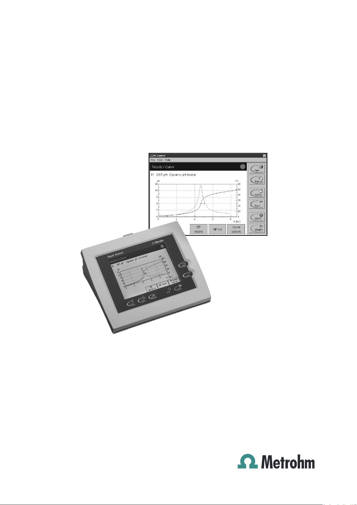
PC Control
Touch Control
Program version PC Control 5.0
Touch Control 5.840.0140
Manual
8.840.8003EN 05.2008 / jb
Page 4

Teachware
Metrohm AG
CH-9101 Herisau
teachware@metrohm.com
This documentation is protected by copyright. All rights reserved.
Although all the information given in this documentation has been checked with great care,
errors cannot be entirely excluded. Should you notice any mistakes please send us your
comments using the address given above.
Page 5

Contents
Table of contents
1 Introduction.......................................................... 1
1.1 Instrument description...................................................................................2
1.2 About the documentation ..............................................................................3
1.2.1 Symbols and conventions........................................................................3
2 Installation ........................................................... 5
2.1 Setting up the Touch Control ........................................................................5
2.1.1 Packaging.................................................................................................5
2.1.2 Checks......................................................................................................5
2.1.3 Location....................................................................................................5
2.2 Touch Control parts and controls .................................................................6
3 Operation.............................................................. 9
3.1 Operating principles: Touch Control ............................................................9
3.1.1 Switching Touch Control on and off.........................................................9
3.1.2 Setting the display contrast of the Touch Control .................................10
3.1.3 Operating the Touch Screen..................................................................10
3.1.4 Entering text and numbers using Touch Control ...................................11
3.2 Operating principles: PC Control............................................................... 13
3.2.1 Starting and stopping the PC Control software .....................................13
3.2.2 Operating the PC Control software ........................................................13
3.3 User interface and controls ........................................................................ 14
3.3.1 User interface of the Touch Control and PC Control .............................14
3.3.2 Controls of the Touch Control and PC Control......................................15
3.3.3 Online help .............................................................................................17
3.4 Program structure ....................................................................................... 18
3.5 Login ............................................................................................................ 19
3.6 Main dialog and structure of the dialog windows..................................... 21
3.7 System settings........................................................................................... 23
3.7.1 Selecting the dialog language ...............................................................23
3.7.2 Setting the date, time and time zone .....................................................23
3.7.3 System-specific dialog options..............................................................24
3.7.4 Routine dialog: disabling functions........................................................25
3.7.5 User administration ................................................................................26
3.7.6 Creating an identification card ...............................................................29
3.7.7 Editing login options...............................................................................30
3.7.8 Audit trail.................................................................................................34
3.7.9 Measured value display .........................................................................36
3.7.10 Acoustic signals .....................................................................................37
3.8 Titrants......................................................................................................... 38
3.8.1 Configuring a titrant in a new intelligent exchange or dosing unit ........39
3.8.2 Configuring a titrant in a new non-intelligent exchange or dosing unit .40
3.8.3 Editing titrant data ..................................................................................40
3.8.4 Titer determination options and data .....................................................41
3.8.5 Exchange unit and dosing unit ..............................................................44
PC Control / Touch Control I
Page 6

Contents
3.8.6 Tubing parameters and parameters for the preparation procedure .....45
3.8.7 Rotating direction of the valve disk (Dosing unit only) ..........................48
3.8.8 Monitoring the GLP test .........................................................................49
3.8.9 Monitoring the working life .....................................................................49
3.9 Sensors........................................................................................................ 50
3.9.1 Configuring a new intelligent sensor......................................................51
3.9.2 Configuring a new non-intelligent sensor ..............................................51
3.9.3 Editing sensor data ................................................................................52
3.9.4 Calibration data (for pH and ISE electrodes only).................................52
3.9.5 Monitoring the calibration interval (for pH and ISE electrodes only).....53
3.9.6 Calibration data limits (for pH and ISE electrodes only) .......................54
3.9.7 Monitoring the working life .....................................................................54
3.10 Device manager........................................................................................... 55
3.10.1 Configuring a new device ......................................................................56
3.10.2 Editing device data ................................................................................56
3.10.3 PC Control and Touch Control...............................................................56
3.10.4 Titrando ..................................................................................................57
3.10.5 USB Sample Processor and Robotic Titrosampler ...............................58
3.10.6 Dosing Interface .....................................................................................68
3.10.7 Printer (Touch Control only) ...................................................................68
3.10.8 Balance ..................................................................................................69
3.10.9 Bluetooth devices...................................................................................71
3.10.10 RS-232/USB Box / Serial ports ..............................................................72
3.10.11 847 USB Lab Link (Touch Control only) ................................................72
3.10.12 PC/LIMS module ....................................................................................73
3.10.13 Send messages as e-mails ...................................................................74
3.10.14 PC keyboard (Touch Control only) ........................................................75
3.10.15 Barcode reader ......................................................................................76
3.11 File manager................................................................................................ 77
3.11.1 Copying files...........................................................................................81
3.11.2 File properties ........................................................................................81
3.11.3 Renaming a file ......................................................................................82
3.11.4 Saving a file ............................................................................................ 82
3.11.5 Card 1 and Card 2 .................................................................................83
3.11.6 Backup and restore................................................................................84
3.12 GLP manager............................................................................................... 87
3.12.1 Automatic system test............................................................................87
3.12.2 Test tools................................................................................................88
3.12.3 GLP tests for measurement and titration...............................................89
3.12.4 System validation ...................................................................................90
3.12.5 Service interval .......................................................................................91
3.12.6 Backup interval.......................................................................................91
3.13 Common variables ...................................................................................... 92
3.13.1 Editing common variables .....................................................................92
3.13.2 Properties of common variables............................................................94
3.13.3 Monitoring the validity ............................................................................95
3.14 Templates .................................................................................................... 96
3.14.1 Sample identification list ........................................................................96
3.14.2 Sample assignment table ......................................................................97
3.14.3 Custom results templates ......................................................................99
3.14.4 Input lines .............................................................................................100
II PC Control / Touch Control
Page 7

Contents
3.14.5 Output lines ......................................................................................... 101
3.14.6 Custom calibration buffers .................................................................. 103
3.14.7 Report header...................................................................................... 104
3.14.8 Custom electrode type........................................................................ 105
3.15 Loading methods ...................................................................................... 107
3.15.1 Loading a method ............................................................................... 107
3.15.2 Creating a new method....................................................................... 108
3.16 Editing parameters.................................................................................... 113
3.16.1 Editing commands .............................................................................. 113
3.16.2 Insert command .................................................................................. 115
3.16.3 Method options ................................................................................... 116
3.16.4 Statistics .............................................................................................. 118
3.16.5 Direct parameters................................................................................ 118
3.16.6 Sample data ........................................................................................ 119
3.16.7 Start and stop options......................................................................... 121
3.16.8 Note ..................................................................................................... 122
3.16.9 Properties ............................................................................................ 123
3.16.10 Saving the determination automat. and sending a PC/LIMS report... 123
3.16.11 Save method ....................................................................................... 125
3.17 Control ...................................................................................................... 126
3.17.1 Statistics .............................................................................................. 126
3.17.2 Sample data silo.................................................................................. 127
3.17.3 Autostart .............................................................................................. 128
3.18 Results and more determination data ..................................................... 129
3.18.1 More determination data ..................................................................... 130
3.18.2 Messages ............................................................................................ 132
3.18.3 Local common variables ..................................................................... 133
3.18.4 Determination properties..................................................................... 133
3.18.5 Save determination.............................................................................. 136
3.18.6 Load determination data ..................................................................... 136
3.18.7 Curves.................................................................................................. 139
3.18.8 Recalculation and re-evaluation.......................................................... 140
3.18.9 Export (PC Control only)...................................................................... 142
3.19 Sample data............................................................................................... 143
3.19.1 Sample data input in the main dialog ................................................. 143
3.19.2 Sample data request in the determination sequence ........................ 144
3.19.3 Sample data silo.................................................................................. 145
3.19.4 Export of sample data ......................................................................... 151
3.20 Determination sequence........................................................................... 152
3.20.1 Carrying out a single determination .................................................... 152
3.20.2 Processing a sample series ................................................................ 153
3.20.3 Stopping determinations manually ..................................................... 154
3.20.4 Live display.......................................................................................... 154
3.20.5 Main dialog "live".................................................................................. 157
3.20.6 Live parameters................................................................................... 158
3.21 Statistics .................................................................................................... 160
3.21.1 Statistical information about the result................................................ 161
3.21.2 Delete statistics data ........................................................................... 162
3.21.3 Adding a determination to a statistics series...................................... 162
3.22 Result silo.................................................................................................. 163
PC Control / Touch Control III
Page 8

Contents
3.22.1 Properties of the result silo ..................................................................164
3.22.2 Saving and loading the result silo........................................................166
3.23 Print……..................................................................................................... 167
3.23.1 Sending or saving a PC/LIMS report ...................................................174
3.23.2 Printing PDF reports.............................................................................175
3.24 Manual control........................................................................................... 176
3.24.1 Measure................................................................................................178
3.24.2 Dosing ..................................................................................................179
3.24.3 Stir ........................................................................................................184
3.24.4 Manual titration.....................................................................................185
3.24.5 Remote .................................................................................................186
3.24.6 USB Sample Processor .......................................................................187
4 Parameters ....................................................... 193
4.1 Titrations.................................................................................................... 193
4.1.1 Dynamic equivalence point titrations (DET) and monotonic equivalence
point titrations (MET)............................................................................197
4.1.2 Endpoint titrations (SET) ......................................................................206
4.1.3 Karl Fischer titrations (KFT)..................................................................212
4.1.4 STAT titrations (STAT) ..........................................................................216
4.1.5 Control device, sensor, dosing device and stirrer...............................223
4.1.6 Direct parameters.................................................................................226
4.2 Measurements (MEAS) ............................................................................. 227
4.3 Measurements (MEAS Cond) ................................................................... 230
4.4 Evaluation .................................................................................................. 231
4.4.1 Evaluation of fixed endpoints (EVAL FIX EP).......................................232
4.4.2 Evaluation of pK value and half neutralization potential
(EVAL pK/HNP) ....................................................................................233
4.4.3 Evaluation of minimum and maximum (EVAL MIN/MAX)....................234
4.4.4 Evaluation of break points (EVAL BREAK) ..........................................235
4.4.5 Rate evaluation (EVAL RATE) ..............................................................236
4.5 Calculations............................................................................................... 238
4.5.1 CALC command ..................................................................................238
4.5.2 CALC LIVE command ..........................................................................242
4.5.3 The formula editor ................................................................................243
4.5.4 Creating custom result templates........................................................246
4.5.5 Loading result templates .....................................................................246
4.5.6 Conversion table of the calculating formula for KF titrations ..............248
4.5.7 Calculable variables .............................................................................248
4.5.8 Result variables as parameters ...........................................................253
4.6 Reports ...................................................................................................... 254
4.7 Calibrating pH electrodes (CAL pH) and ISE (CAL Conc) ..................... 257
4.8 Calibrating conductivity measuring cells (CAL Cond) ........................... 263
4.9 Electrode test for pH electrodes (ELT) .................................................... 265
4.10 Dosing and liquid handling ...................................................................... 270
4.10.1 Dosing (ADD) .......................................................................................270
4.10.2 Liquid handling (LQH).......................................................................... 270
4.10.3 Preparing (PREP) and emptying (EMPTY) ..........................................272
4.10.4 Monitored dosing (DOS)......................................................................273
4.11 Communication ......................................................................................... 278
IV PC Control / Touch Control
Page 9

Contents
4.11.1 Scanning lines (SCAN)........................................................................ 278
4.11.2 Setting lines (CTRL)............................................................................. 278
4.11.3 Receive data (SCAN RS)..................................................................... 279
4.11.4 Send data (CONTROL RS).................................................................. 279
4.12 Automation ................................................................................................ 280
4.12.1 Move (MOVE) ...................................................................................... 280
4.12.2 Lift (LIFT).............................................................................................. 281
4.12.3 Pump (PUMP)...................................................................................... 281
4.12.4 Rack reset (RACK) .............................................................................. 282
4.12.5 Sample variable (SAMPLE) ................................................................. 282
4.12.6 Subsequence (SUBSEQ) .................................................................... 282
4.13 Various commands ................................................................................... 285
4.13.1 Stirring (STIR) ...................................................................................... 285
4.13.2 Waiting (WAIT) ..................................................................................... 285
4.13.3 Requesting sample data and common variables (REQUEST) .......... 286
4.13.4 Acoustic signal (BEEP)........................................................................ 286
4.13.5 Signature (SIGN) ................................................................................. 286
4.13.6 End (END) ........................................................................................... 286
5 Troubleshooting – Maintenance ...................... 287
5.1 Troubleshooting ........................................................................................ 287
5.1.1 Editing methods .................................................................................. 287
5.1.2 Sample series...................................................................................... 287
5.1.3 Results, calculations and statistics ..................................................... 288
5.1.4 SET titrations........................................................................................ 289
5.1.5 KF titrations.......................................................................................... 290
5.1.6 STAT titrations ..................................................................................... 291
5.1.7 Sensor data ......................................................................................... 292
5.1.8 Print...................................................................................................... 292
5.1.9 Manual Operation................................................................................ 293
5.1.10 USB Sample Processor....................................................................... 293
5.1.11 File manager........................................................................................ 294
5.1.12 Miscellaneous...................................................................................... 294
5.2 Diagnosis................................................................................................... 295
5.2.1 LCD test............................................................................................... 295
5.2.2 Temperature monitoring (Temperature control) ................................. 295
5.2.3 Formatting a memory card (Format card) .......................................... 296
5.2.4 PCMCIA specification (PCMCIA power selection).............................. 296
5.2.5 Service ................................................................................................. 296
5.2.6 Touch screen test................................................................................ 296
5.2.7 Software update .................................................................................. 297
5.2.8 822 Curve Simulator............................................................................ 301
5.2.9 Remove PCMCIA card 1/2 .................................................................. 302
5.3 Maintenance .............................................................................................. 303
5.3.1 Changing the batteries (Touch Control only)...................................... 303
5.3.2 RAM initialization (RAM Init, Touch Control only)................................ 304
6 Appendix ........................................................... 305
6.1 Technical data ........................................................................................... 305
6.1.1 Touch screen....................................................................................... 305
6.1.2 Interfaces ............................................................................................. 305
6.1.3 Power supply....................................................................................... 305
PC Control / Touch Control V
Page 10

Contents
6.1.4 Safety specifications ............................................................................305
6.1.5 Electromagnetic compatibility (EMC) ..................................................306
6.1.6 Ambient temperature ...........................................................................306
6.1.7 Dimensions ..........................................................................................306
6.2 Remote box................................................................................................ 307
6.2.1 Pin occupancy of the remote connection at the Remote box .............307
6.2.2 Functions of the individual remote lines ..............................................308
6.3 RS-232/USB Box........................................................................................ 309
6.3.1 RS-232 parameters ..............................................................................309
6.3.2 RS-232 pin occupancy.........................................................................310
6.4 Stored buffer series for CAL pH............................................................... 311
6.5 Liquid handling – schematic process ...................................................... 316
6.5.1 Port definitions of the dosing unit ........................................................316
6.5.2 Pipetting equipment.............................................................................316
6.5.3 Pipetting sequences ............................................................................317
6.6 Titration and measuring modes in the Titrando system......................... 320
6.7 Import of Titrino methods (PC Control only)........................................... 321
6.8 Arithmetic algorithms in the Titrando ...................................................... 324
6.9 Standard equipment.................................................................................. 326
6.9.1 840 Touch Control................................................................................326
6.9.2 PC Control software with Dongle (6.6050.400) ...................................326
6.9.3 PC Control software, demo version (6.6050.405) ...............................326
6.10 Additional devices and optional accessories ......................................... 327
6.10.1 Miscellaneous accessories..................................................................327
6.10.2 Communication....................................................................................327
6.11 Warranty and conformity .......................................................................... 329
6.11.1 Warranty ...............................................................................................329
6.11.2 Declaration of Conformity ....................................................................330
6.11.3 Declaration of Conformity ....................................................................331
6.11.4 Quality Management Principles ...........................................................332
7 Index ................................................................. 333
VI PC Control / Touch Control
Page 11

Contents
List of illustrations
Fig. 1.1: The Titrando system ...................................................................................................1
Fig. 2.1: Front view of the Touch Control.................................................................................. 6
Fig. 2.2: Rear view of the Touch Control .................................................................................. 7
Fig. 3.1: Different ways of navigation on the Touch Screen................................................... 10
Fig. 3.2: Touch Control user interface .................................................................................... 14
Fig. 3.3: PC Control user interface.......................................................................................... 14
Fig. 3.4: Online help, PC Control ............................................................................................ 17
Fig. 3.5: Program structure .....................................................................................................18
Fig. 3.6: Audit Trail .................................................................................................................. 35
Fig. 3.7: Dosing unit port occupancy and tubing connections .............................................. 45
Fig. 3.8: Exchange unit tubing connections ........................................................................... 46
Fig. 3.9: Data memory arrangement....................................................................................... 77
Fig. 3.10: PC Control: Folder structure for Card 1and Card 2 ............................................... 79
Fig. 3.11: Data transfer Backup/Restore ................................................................................ 84
Fig. 4.1: Reagent addition for DET ....................................................................................... 193
Fig. 4.2: Reagent addition for MET....................................................................................... 194
Fig. 4.3: Reagent addition for SET........................................................................................ 194
Fig. 4.4: Reagent addition for KFT........................................................................................ 195
Fig. 4.5: Reagent addition for STAT...................................................................................... 196
Fig. 4.6: Equivalence point recognition and numbering in windows ................................... 202
Fig. 4.7: Tubbs method for determining the equivalence point ........................................... 203
Fig. 4.8: Reagent addition during endpoint titrations with SET............................................ 207
Fig. 4.9: Control range size................................................................................................... 208
Fig. 4.10: Reagent addition and control range for STAT...................................................... 217
Fig. 4.11: Action "Exit method" or "Skip command".............................................................. 220
Fig. 4.12: Action "Hold" ......................................................................................................... 220
Fig. 4.13: Action "Wait" .......................................................................................................... 221
Fig. 4.14: Setting the stirring rate and speed ....................................................................... 225
Fig. 4.15: Determining the pK value from the titration curve ................................................ 233
Fig. 4.16: Evaluation of minimum and maximum ................................................................. 234
Fig. 4.17: Evaluating a breakpoint ........................................................................................ 236
Fig. 4.18: Definition of volume and dosing rate.................................................................... 273
Fig. 4.19: Definition of volume and dosing time................................................................... 274
Fig. 4.20: Definition of dosing rate and dosing time ............................................................ 274
Fig. 5.1: Changing the batteries for Touch Control .............................................................. 303
Fig. 6.1: View of the connections of the optional 6.2148.010 Remote box.......................... 307
Fig. 6.2: Pin occupancy at remote interface......................................................................... 307
Fig. 6.3: View of the connections of the optional RS-232/USB Box..................................... 309
Fig. 6.4: View of the RS-232 connections on the RS-232/USB Box..................................... 310
Fig. 6.5: Port occupancy of the Dosing unit ......................................................................... 316
PC Control / Touch Control VII
Page 12

Contents
VIII PC Control / Touch Control
Page 13
1 Introduction
1 Introduction
This manual gives you a comprehensive overview of the functions of the
Touch Control and the PC Control software for operating the Titrando
system. The Titrando system can either be operated with the Touch
Control with touch-sensitive screen as a stand-alone-system or with
the PC software PC Control. In this case the varied possibilities of a
computer can be utilized.
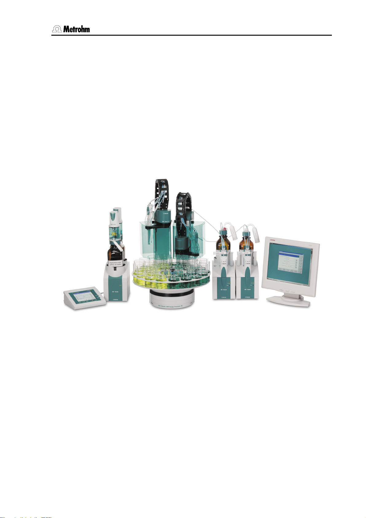
Figure 1.1 shows the versatility of the Titrando system. On the left a
Touch Control for operating a Titrando with external dosing devices is
shown. To the right you can see an automation system consisting of
USB Sample Processor, Titrando with internal dosing drive and Dosimat controlled by the PC Control software.
Fig. 1.1: The Titrando system
PC Control / Touch Control 1
Page 14

1.1 Instrument description
1.1 Instrument description
There are two different ways of operating the Titrando system: with
Touch Control the operation is via a touch-sensitive screen. A computer with installed PC Control software is a version with several additional features which directly utilize the communications and storage facilities of a PC. The import of Titrino methods is only possible with the
PC Control software. Both programs have a context-sensitive online
help function.
The appearance and operation of the two versions are almost identical;
this means that if you work with Touch Control then you can also use
the PC Control software without any problems and vice-versa. Methods,
determinations, sample data silos, result silos and backups are 100 %
compatible.
This manual describes the operation of the Titrando system with both
the PC Control software and Touch Control. If the description applies to
only one of these versions then this is indicated in the text.
Further documents can be found on the installation CD of PC Control.
Visit the web page http://products.metrohm.com
always find the most recent documents ready for download as PDF
files.
as well. There you will
2 PC Control / Touch Control
Page 15
1 Introduction
1.2 About the documentation
Attention!
Please read through this documentation carefully before putting the
instrument into operation. The documentation contains information
and warnings which have to be followed by the user in order to ensure
safe operation of the instrument.
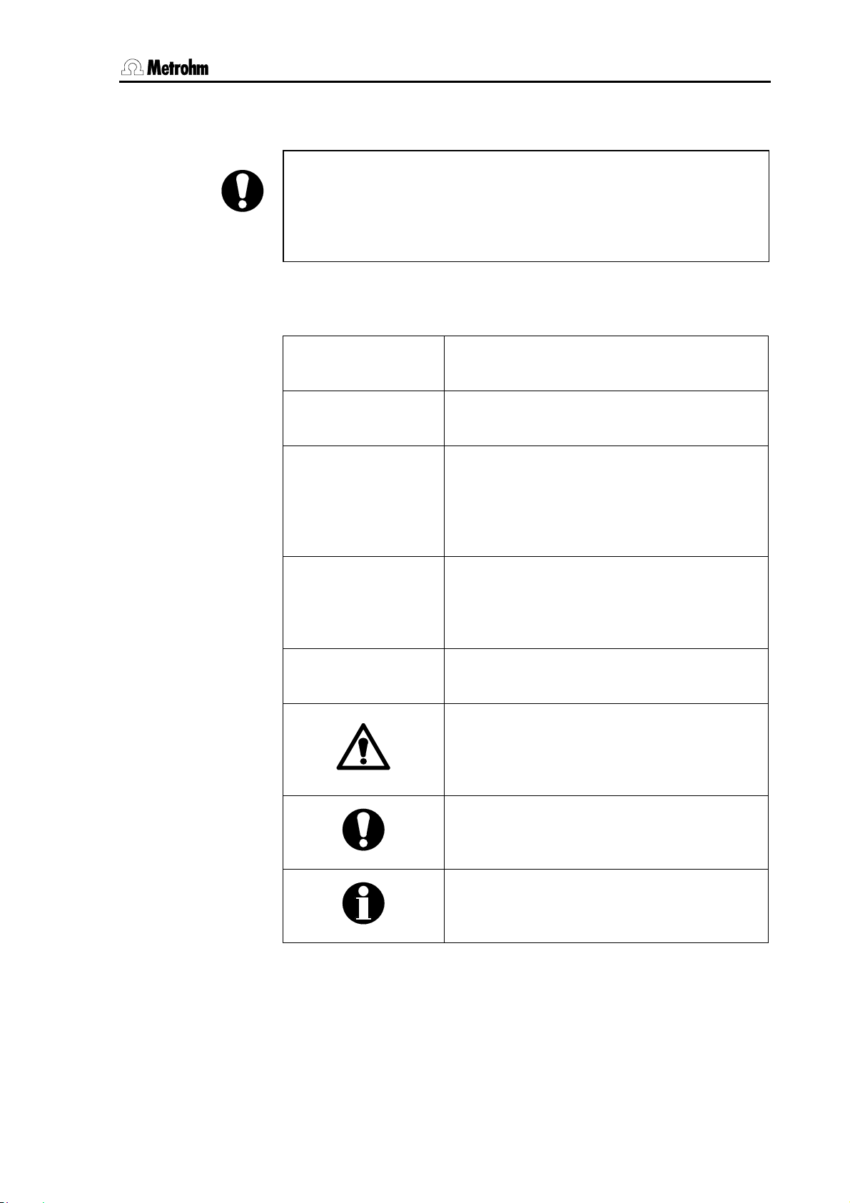
1.2.1 Symbols and conventions
The following symbols and styles are used in this documentation:
9
User
[Next]
Numbers of the parts and controls
see illustrations in Section 2.2.
Instructions
carry out the instructions step by step.
Parameters, input values
Parameters and values for parameters, dialog title.
Menu, menu item
in the PC Control software.
Button
on the user interface.
Fixed key
on the Touch Control.
<Ctrl>
Key
on the computer keyboard.
Danger/Warning
This symbol indicates a possible risk of injury to the user and possible damage to the
instrument or its components.
Attention
This symbol indicates important information
that you should read before continuing.
Information
This symbol indicates additional information
and tips that may be particularly useful.
PC Control / Touch Control 3
Page 16

1.2 About the documentation
4 PC Control / Touch Control
Page 17

2 Installation
2 Installation
Connecting the Touch Control to the Titrando is described in the
manual for the Titrando as well as the setup of the titration system with
peripheral devices such as stirrers and dosing devices.
2.1 Setting up the Touch Control
2.1.1 Packaging
The Touch Control and its specially packed accessories are supplied in
very protective special packaging. Please store this packaging in a safe
place; it is the only way in which the safe transport of the instrument can
be guaranteed.
2.1.2 Checks
Immediately after receipt, check whether the shipment has arrived
complete and without damage by comparing it with the delivery note.
2.1.3 Location
The Touch Control has been designed for internal laboratory use and
should not be used in explosion-endangered locations.
Place the instrument on a suitable vibration-free laboratory bench,
protected as much as possible from corrosive atmospheres and
contact with chemicals.
Choose a location where the temperature is usually between +5 °C and
+40 °C. The instrument should be protected against excessive
variations in temperature and direct sunlight.
PC Control / Touch Control 5
Page 18
2.2 Touch Control parts and controls
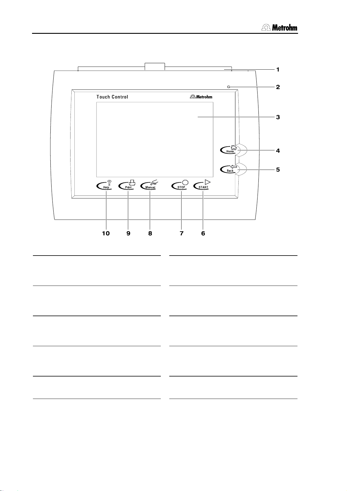
2.2 Touch Control parts and controls
1 Protective cover for card slots
Accommodates two PCMCIA or
CompactFlash memory cards.
2 “ON” LED
Lights up when instrument is switched
on.
3 Touch Screen display
4 Fixed key [Home]
Changes to main dialog.
5 Fixed key [Back]
Changes to previous dialog.
Fig. 2.1: Front view of the Touch Control
6 Fixed key [START]
Starts the current method.
7 Fixed key [STOP]
Stops the run.
8 Fixed key [Manual]
Opens the dialog for manual operation
of the titration system.
9 Fixed key [Print]
Opens the print dialog for manual
printout of a report.
10 Fixed key [Help]
Opens the context-sensitive help.
6 PC Control / Touch Control
Page 19
2 Installation
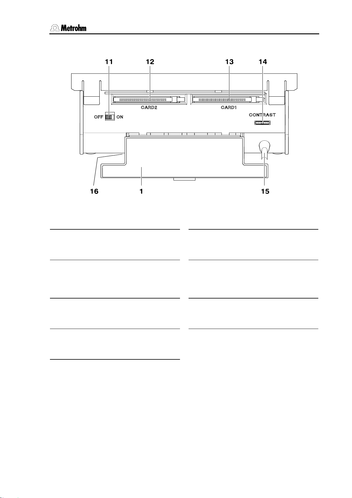
Fig. 2.2: Rear view of the Touch Control
1 Protective cover for card slots
Must be closed during operation to
protect the electronics from splashes.
11 On/Off switch
Touch Control must be shut down
properly by switching it off before the
current supply is interrupted.
12 Card slot 2
Accommodates one PCMCIA or
CompactFlash memory card.
13 Card slot 1
Accommodates one PCMCIA or
CompactFlash memory card.
Contrast controller for display
14
15 Connection cable
for connecting the Touch Control to the
Titrando ("Controller" connection).
16 Type plate
With device number and serial number
PC Control / Touch Control 7
Page 20

2.2 Touch Control parts and controls
8 PC Control / Touch Control
Page 21
3 Operation
3 Operation
The most important points concerning the operation of the Touch
Control and PC Control are described in this section. As the
appearance of the operator interface and the functions are almost
identical, only the PC Control operator interface is shown. If individual
functions are only available in Touch Control or in the PC Control
software then this is indicated accordingly in the text.
The arrangement of the program and the operating concept are
identical for Touch Control and the PC Control software. In Touch
Control operation is carried out via a touch-sensitive screen (Touch
Screen), in PC Control the software is operated by using a mouse and
the PC keyboard. This results in several system-specific operating
possibilities.
3.1 Operating principles: Touch Control
3.1.1 Switching Touch Control on and off
A Touch Control which is properly connected to a Titrando is switched
on and off with ON/OFF switch 11 on the rear panel of the instrument.
Attention!
The Touch Control must be shut down properly by switching it off
with the ON/OFF switch on the rear panel of the instrument before the
current supply is interrupted. Otherwise there is the risk that data may
be lost. As power is provided to the Touch Control via the Titrando,
the Titrando must never be separated from the mains supply (e. g. by
switching it off via a multiple outlet strip) before the Touch Control has
been switched off. When the Touch Control is switched on all the
other peripheral devices (e. g. printer) must already be switched on.
We recommend the following procedure:
Connect all the instruments (Titrando and peripheral devices) to the
mains supply via a multiple outlet strip with mains switch.
When switching on first switch on the multiple outlet strip with the
Touch Control switched off. Then switch on the Touch Control.
When switching off proceed in the reverse order. First switch off
the Touch Control. Then switch off all the peripheral devices via the
multiple outlet strip switch.
PC Control / Touch Control 9
Page 22
3.1 Operating principles: Touch Control
3.1.2 Setting the display contrast of the Touch Control
Knob 14 for setting the contrast of the Touch screen is located on the
rear panel of the instrument. Move it in one direction and hold it tight
when it reaches the stop in order to increase or reduce the contrast.
Use the fixed key [Help] in the main dialog to open the online help.
Set the contrast so that the scroll bar surface is light gray and the
margins to the left and below are dark gray (see Section
3.3.2).
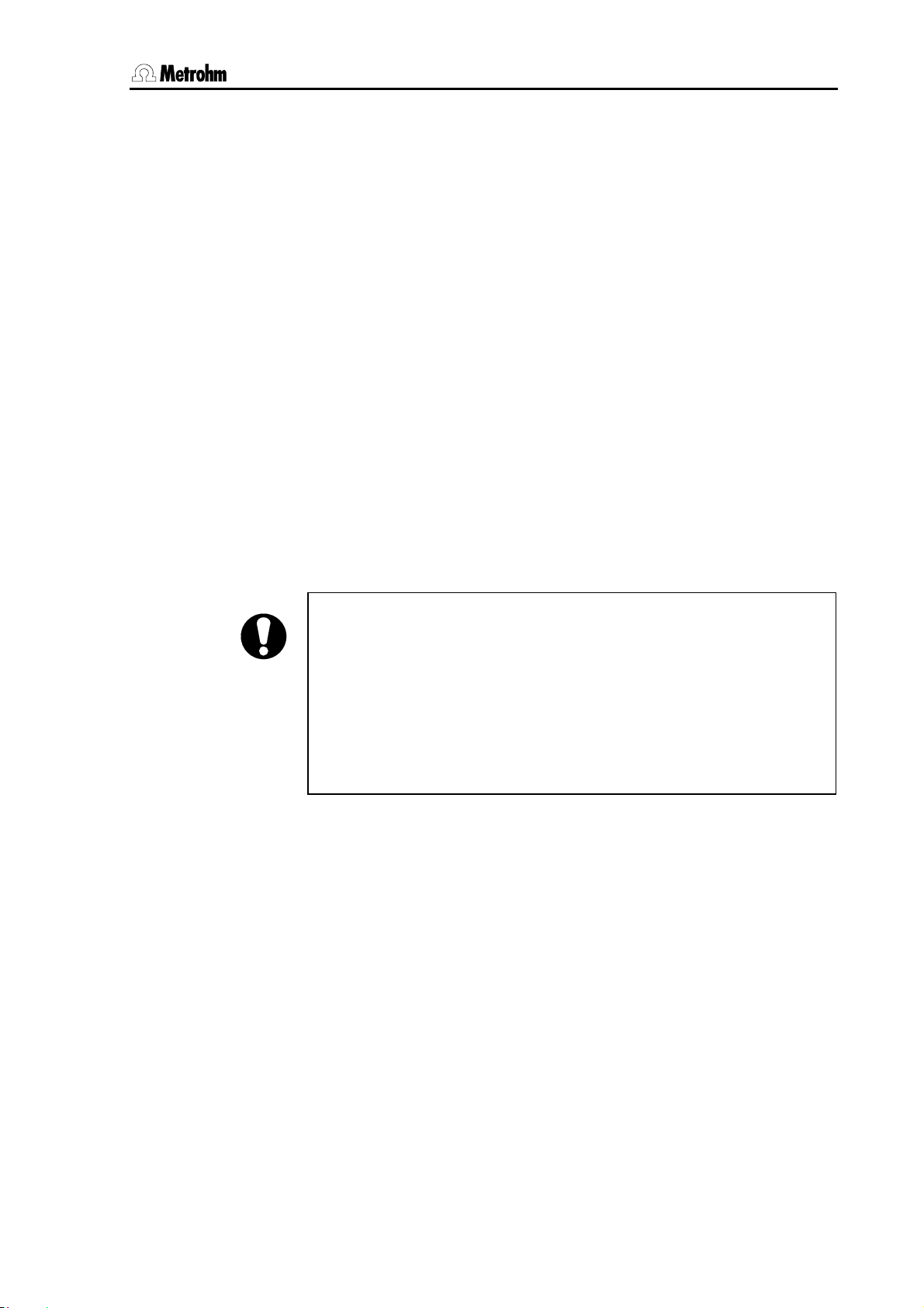
3.1.3 Operating the Touch Screen
The whole screen surface is touch-sensitive. Just touch some of the
buttons on the screen to see how to operate the Touch screen. You can
always return to the main dialog by touching [Home].
In order to activate an element on the Touch Control user interface just
touch the screen with your fingertip, finger nail, the eraser of a pencil or
a stylus (special tool for operating Touch screens); see below:
Fig. 3.1: Different ways of navigation on the Touch Screen
10 PC Control / Touch Control
Attention!
Never touch the Touch screen with a pointed or sharp object such as
a ballpoint pen.
If you use the standard settings then touching an active operating
element creates a sound.
Page 23
3 Operation
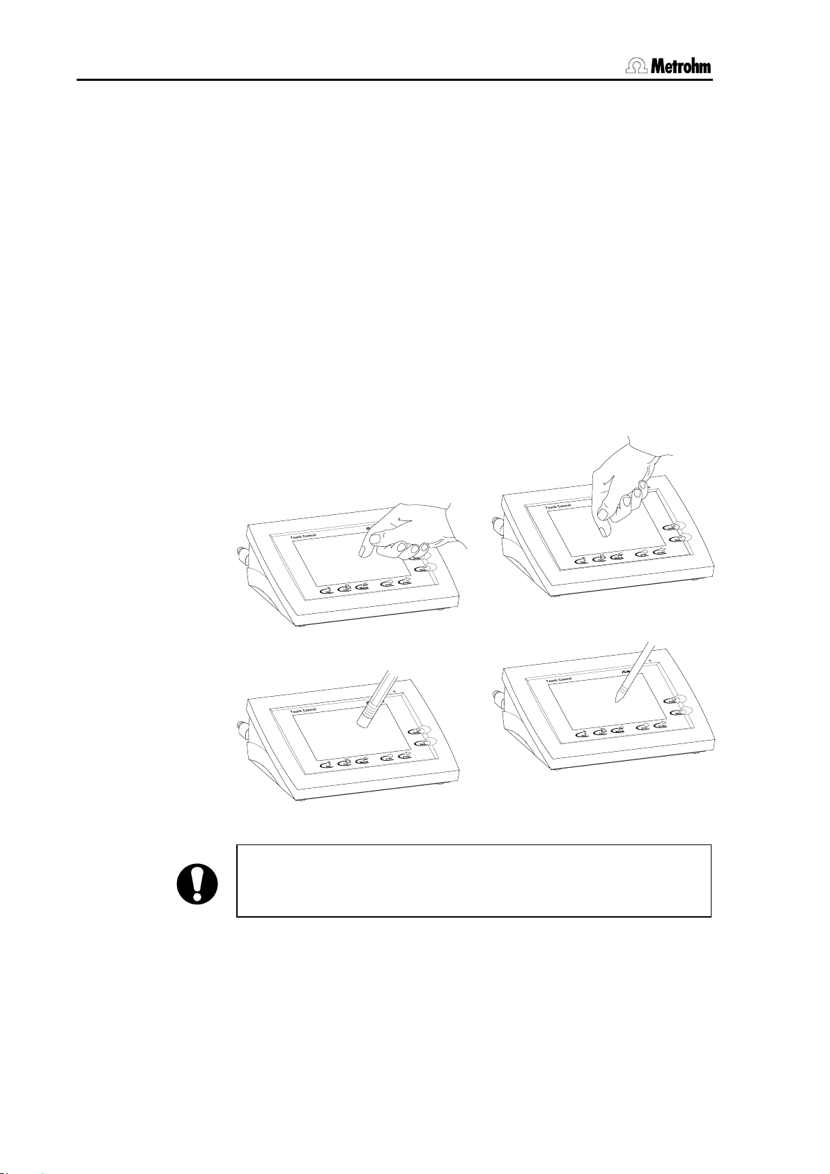
3.1.4 Entering text and numbers using Touch Control
Just touch an input field, e. g. User in the main dialog, to open the
Text editor.
In the text editor the name of the parameter is shown in front of the
input field.
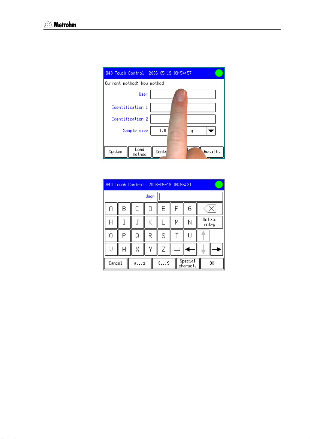
Touch the required character. Apart from the capital letters which
first appear, there are also sets of characters with lower case letters,
numbers and mathematical signs as well as three blocks of special
characters. You can switch to the required set of characters with the
[a...z], [0...9] and [Special characters] buttons and
between the blocks of special characters with [More]. The
backspace button [⌫] deletes the character in front of the cursor.
[Delete entry] deletes the whole text. With the arrow buttons the
cursor can be positioned in the text.
Accept your entry with [OK] or [Back], or reject it with [Cancel].
In input fields for numerical values the number editor will open. The
required value is entered directly via the indicated keys. A stop is
automatically used as the decimal separator.
For example, touch the input field for the Stop volume in a titration
command.
PC Control / Touch Control 11
Page 24
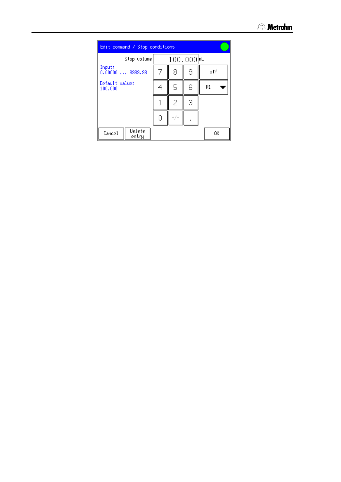
3.1 Operating principles: Touch Control
To the left of the block of numbers you can see the input range
together with its default value. If not only numbers but also special
values (e. g. off) can be entered for a parameter then the
corresponding buttons will be shown to the right of the block of
numbers. For many method parameters it is also possible to enter a
result which has previously been defined in the method sequence as a
value. The result variable can be selected under [R1] (see
Section 4.5.1).
Touch the required number or special value. The whole entry can be
deleted with [Delete entry].
Accept your entry with [OK] or [Back], or reject it with [Cancel].
To make the entry of texts and numbers easier you can also connect an
external PC keyboard with a USB connection to a Titrando system with
Touch Control (see Section
3.10.14).
12 PC Control / Touch Control
Page 25
3 Operation
3.2 Operating principles: PC Control
3.2.1 Starting and stopping the PC Control software
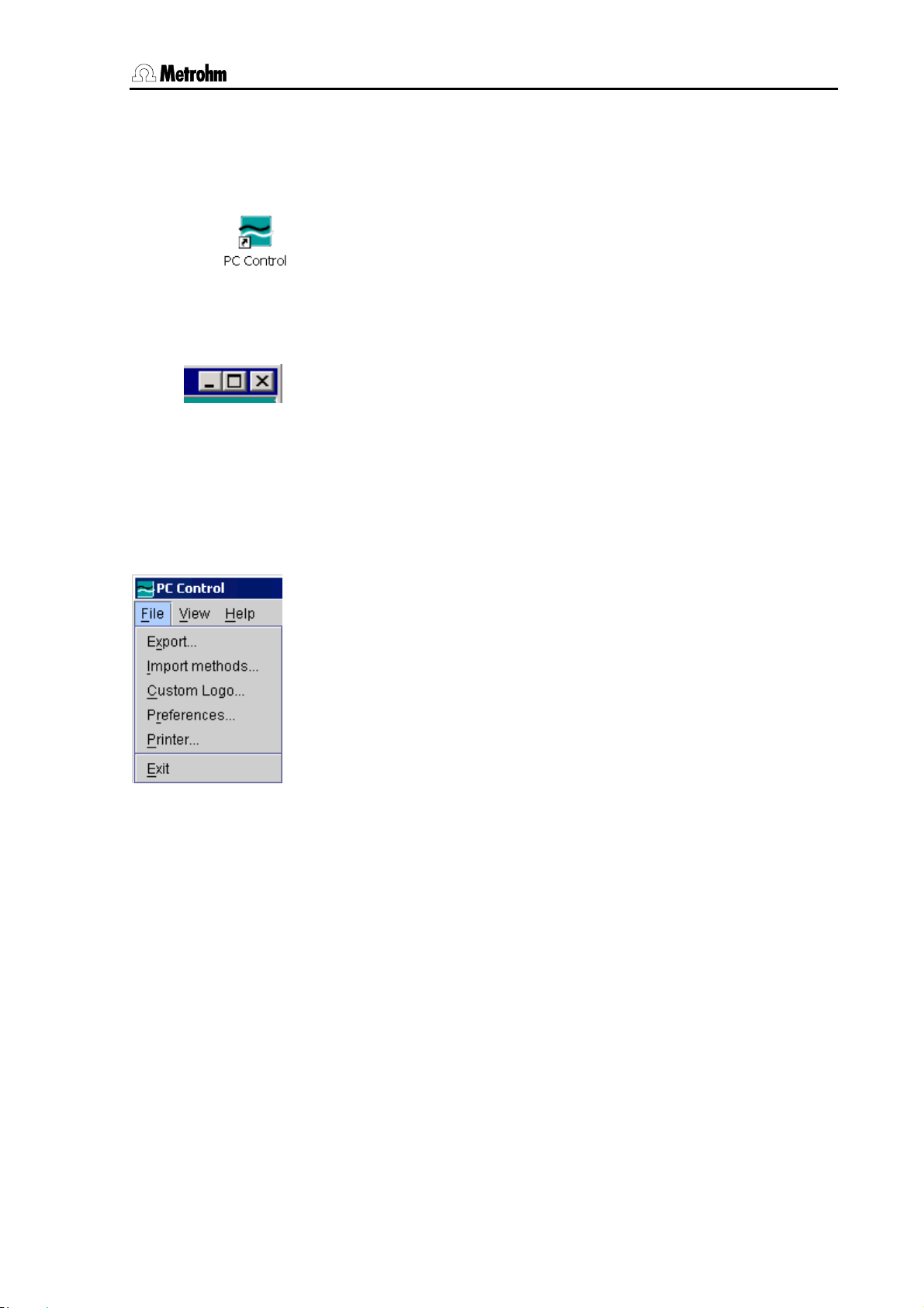
A double-click on the PC Control icon, which is automatically copied
onto the Windows desktop during installation, starts the program.
Alternatively you can start the program in the menu
Start/Program Files/Metrohm/PC Control or execute the file
PcControl.exe under C:\Program Files\Metrohm\PC Control\bin
(installation with the default path) with a double-click. After the program
start the main dialog window opens (see Section
The program can be closed by either clicking on [×] (close) in the top
right-hand corner of the program window or by clicking on the menu
item Exit in the File menu. When the PC Control software is started
the program window cannot be closed.
3.2.2 Operating the PC Control software
The PC Control program is operated within the main dialog window in
exactly the same way as Touch Control. All the elements of this
program window as well as the fixed keys can be activated or selected
with a mouse-click.
3.3).
PC Control also has a menu bar via which the specific PC Control
functions can be selected.
In addition, the controls of the main dialog display can be accessed
and operated via the PC keyboard. A cursor is provided; this can be
moved from one item to the next by using the tab key. An item selected
in this way is activated by the space bar. Input fields can be edited
directly.
PC Control / Touch Control 13
Page 26
3.3 User interface and controls
3.3 User interface and controls
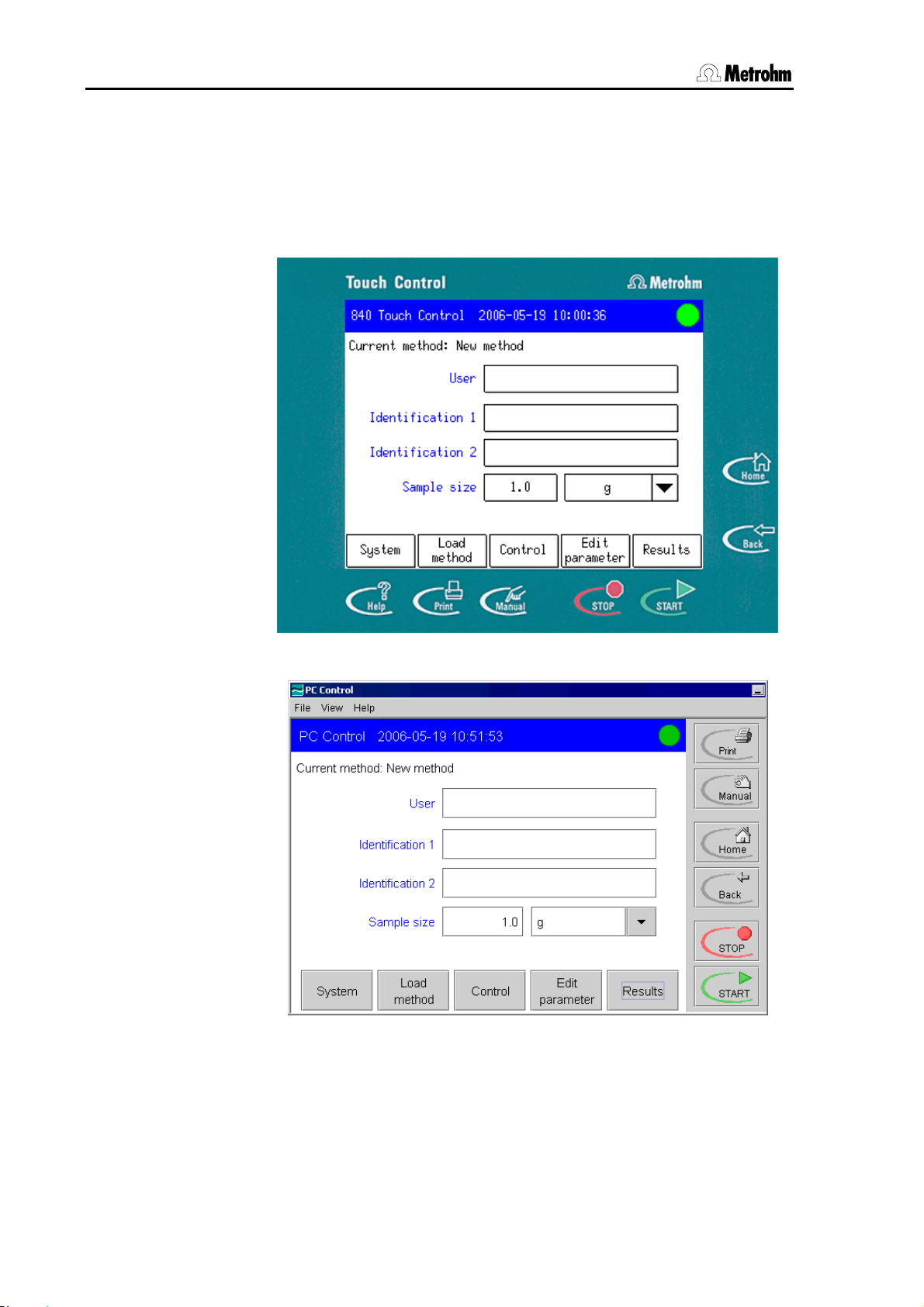
3.3.1 User interface of the Touch Control and PC Control
In both cases the user interface consists of the dialog window itself
and the fixed keys.
Fig. 3.2: Touch Control user interface
Fig. 3.3: PC Control user interface
The PC Control program has an additional menu bar.
14 PC Control / Touch Control
Page 27
3 Operation
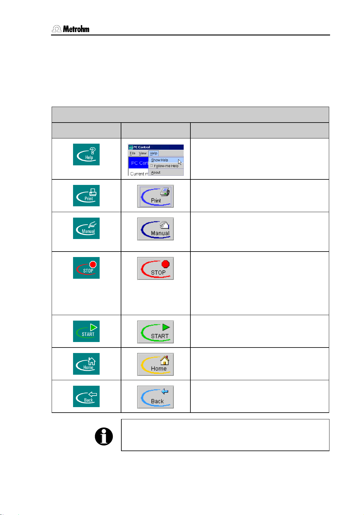
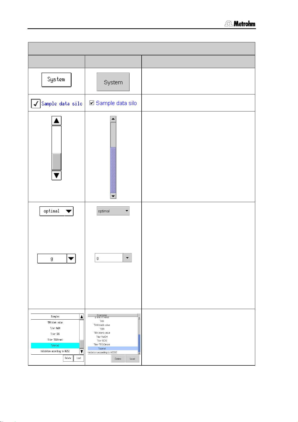
3.3.2 Controls of the Touch Control and PC Control
Both the Touch Control and the PC Control software systems have
changing controls within the dialog window and fixed keys outside the
dialog window which are accessible at all times. The following table lists
the functions of all the controls:
Fixed keys
Touch Control PC Control Fixed key function
Opens the context-sensitive online help
function (see Section
Opens the print dialog for the manual
printout of the reports (see Section
3.3.3).
3.23).
Opens the dialog for the manual operation of
the titration system (see Section
the PC Control a separate dialog window is
3.24). With
opened.
Stops the determination sequence. The
command which is currently being
processed will be stopped immediately and
the results page will be shown (see
Section
3.20.3). The following commands
(e. g. calculations, REPORT commands) will
not be carried out.
Starts the current method; this will then be
processed (see Section
3.20).
Switches to main dialog.
Switches to previous dialog.
Note!
The settings made in a dialog window with PC Control will only be
stored when the dialog is exited with [Back] or [Home].
PC Control / Touch Control 15
Page 28
3.3 User interface and controls
Dialog elements
Touch Control PC Control Fixed key function
Active buttons are indicated by a frame.
Inactive buttons are shown in gray.
Tip or click on a checkbox to activate it.
Use the scroll bar in order to navigate
quickly through lists or longer text displays.
To move up and down in the list push the
scroll bar up and down with your finger or
with the left-hand mouse key pressed down.
The selection list can be recognized by the
arrow to the right of the text. In an open list
the element currently selected is shown with
a background bar. Select the required
element in the list with the finger or mouse.
This entry will then be transferred directly to
the input field.
If the input field and arrow are separated by
a line then this means that you can also
make your own entries. In the Touch Control
you can open the text editor by touching the
input field. In PC Control you can click
directly on the input field and enter
text/numbers. The selection list is opened
with the arrow.
In the list the selected line is indicated by a
light blue bar. You should first mark the line
to be selected and then activate the button
for the function you want to apply to the
selected element.
16 PC Control / Touch Control
Page 29
3 Operation
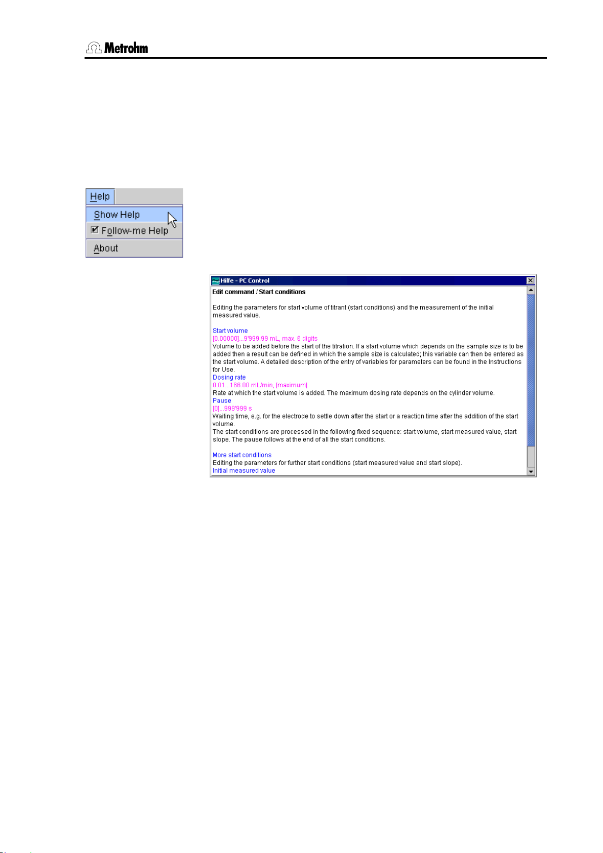
3.3.3 Online help
This manual is chiefly intended to describe the procedure for
configuring the system, carrying out a determination and evaluating and
storing the data. For further details about the individual parameters,
e. g. input ranges, you should use the context-sensitive online help,
which will rapidly provide you with the information you require at any
point.
In Touch Control you can open the online help with the [Help] fixed
key. In the PC Control software the online help is opened with the
<F1> key on the computer keyboard or started by clicking on the
menu item Show help in the Help menu. If you also activate the item
Follow-me help in this menu then the help window will be updated
each time that the dialog is changed.
Fig. 3.4: Online help, PC Control
The following markings apply to the online help for Touch Control and
PC Control:
Blue text Parameters and buttons which are explained.
Violet text Input values for the parameters.
[Value] Default value for a parameter.
PC Control / Touch Control 17
Page 30
3.4 Program structure
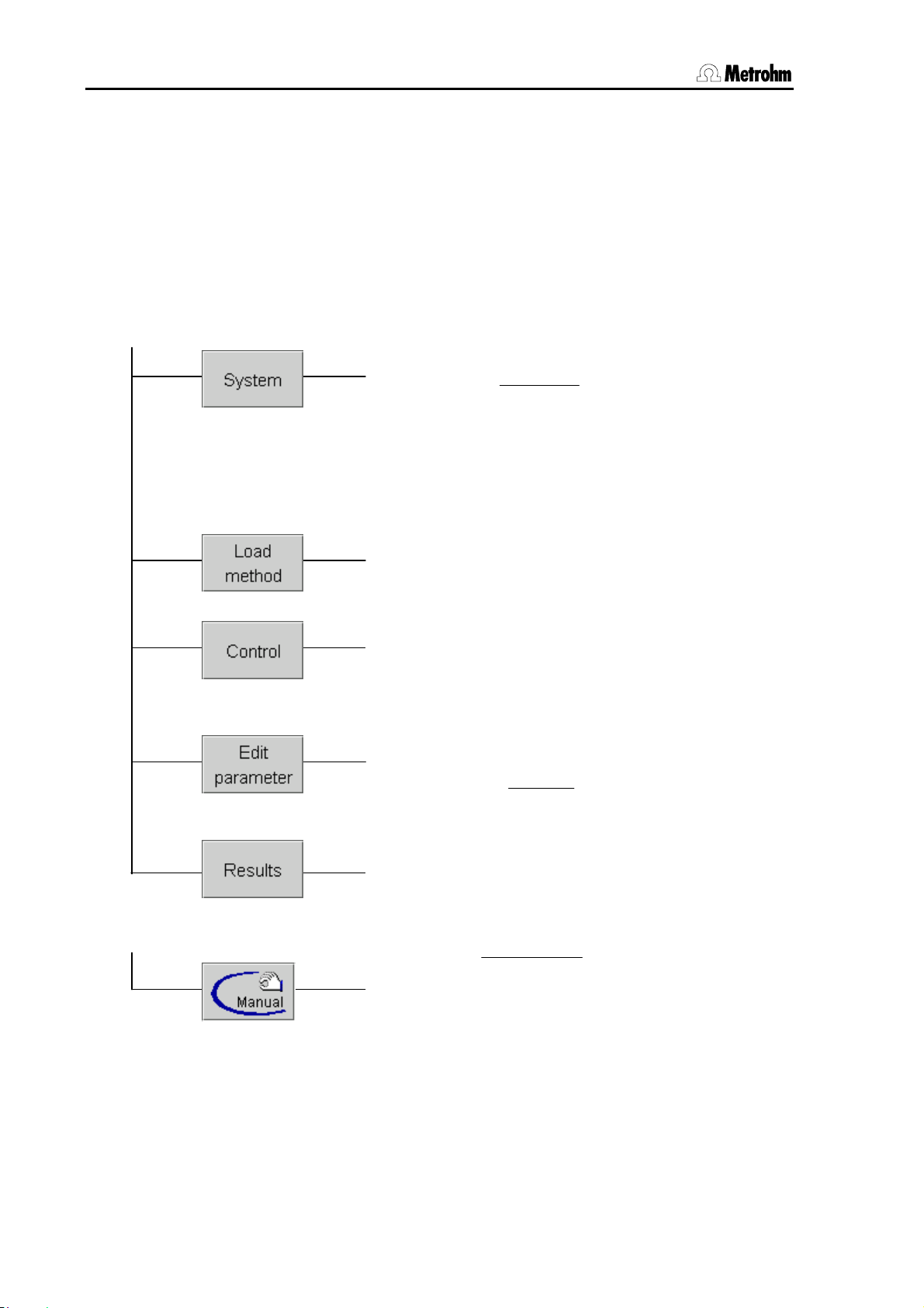
3.4 Program structure
The program structure is arranged so that the most important functions
can be accessed with only a few clicks or touches on the buttons.
Functions which are not often used in routine operation, such as
changing the system settings or editing individual parameters in a
method, can be found in lower dialog levels. In order to provide an
overview of the structure of the program we have summarized the most
important functions in the following diagram:
Main dialog
Fixed keys
├ System settings
├ Titrants
├ Sensors
├ Device manager
├ File manager
├ GLP manager
├ Common variables
├ Templates
└ Diagnosis
├ New method
├ Internal memory
├ Card 1
└ Card 2
├ Statistics
├ Sample data silo
├ Autostart
├ Sample number
└ Logout
├ Save method
├ Method options
├ Insert command
├ Delete command
└ Edit command
├ Result silo
├ Statistics
├ Recalculate
├ Curve
└ More data
├ Measure
├ Dosing
├ Stir
├ Manual titration
├ Remote
└ Sample Processor
├
Date and time
├ Language
├ User administration
└ Dialog options
├
Statistics
├ Save automatically
├ Send PC/LIMS report
├ Method note
├ Start/Stop options
└ Sample data
├
Load / Save
└ Properties
Fig. 3.5: Program structure
18 PC Control / Touch Control
Page 31

3 Operation
3.5 Login
Depending on how your Titrando system is configured, you may have
to use the User login function before you can work with the system.
User administration is carried out by a user with administrator rights
(see Section
identifying the user: by the entry of the user name or by using an
identification card, on which the user name and the routine dialog
settings are stored. If a password is required for identification then this
will be requested on login in both cases.
In the following example the user must identify himself/herself by
entering a name and password.
3.7.5 to Section 3.7.7). There are two different ways of
The first time that you log in you must first define your password with
[Change password]:
First enter the password under New password and enter it again
under Confirm password for confirmation. Please note that this
password can not be used multiple times.
Enter your password in the login dialog. If the user is defined in the
list of users and if the correct password has been entered then the
main dialog will open.
If you have to identify yourself with an identification card then you will be
requested to insert it.
PC Control / Touch Control 19
Page 32

3.5 Login
In Touch Control you must always insert your identification card in
Card slot 1. In PC Control ask your system administrator to tell you the
drive to be used. If a password additionally has to be entered then the
corresponding dialog will be opened automatically; otherwise the main
dialog will open directly.
20 PC Control / Touch Control
Page 33

3 Operation
3.6 Main dialog and structure of the dialog windows
This section provides an overview of the structure of the dialog windows
and the various dialog elements. The user interface without the fixed
keys [Help], [Print], [Manual], [STOP], [START], [Home] and [Back]
is known as the dialog window (or just dialog):
• In the status line (blue bar) the titles of the previous dialog and
current dialog are normally shown. Only in the main dialog the type
of instrument and the actual date and time are shown in this status
line. In the live display (see Section
method is shown.
• In the right top corner the current status of the system is shown:
Instrument in normal working condition (ready), i.e. a
determination can be started.
Conditioning is running (for SET and KFT titrations)
Conditioning has been manually stopped with
[Hold]. It can be continued with [Continue].
Conditioning is finished; the sample will be titrated
up to the endpoint and held there.
A determination sequence has been started.
[START] and [Print] are not active now.
3.20.4) the name of the current
The determination sequence has been interrupted
manually with [Hold] or automatically. It can be
restarted with [Continue].
PC Control / Touch Control 21
Page 34

3.6 Main dialog and structure of the dialog windows
A run has been started in the "Manual control" dialog
window.
A fault has occurred during the manual operation of
the System.
• In the main dialog you can enter or select the user if you are not
working with login (see Section
sample data (see Section
3.19.1).
3.7.5). You can also edit the
• The buttons at the lower margin of the dialog change their function
according to the dialog shown. They are usually used to open a
new dialog. You can open the following dialogs from the main
dialog:
Instrument-specific system settings, titrant and
sensor management, management and
configuration of peripheral devices, file
management, GLP functions, edits systemspecific variables, creates various templates,
diagnostic functions and software updates.
Loads a method from the method memory and
creates a new method.
Switches statistics on/off, switches sample
data silo on/off, deletes sample data silo
(Touch Control only), autostart, sample
number, system logout and deletes statistics.
Edits method command list and the
parameters of the current method.
Shows the results of the current determination,
recalculation and re-evaluation of the current
determination, views, saves and loads
determination data, views statistics results and
results silo.
22 PC Control / Touch Control
Page 35

3 Operation
3.7 System settings
A range of system-specific settings and configurations is described in
this section. You should first select the dialog language and set the
date and time. You can also configure the dialog for routine use and
create a list of users. You can make various settings concerning the
measured value display and output of acoustic signals.
3.7.1 Selecting the dialog language
Open the dialog System/System settings.
Open the selection list Dialog language with the arrow and select
the language.
Exit the dialog with [Home] so that the setting applies to all dialogs.
(From this particular dialog you can also return to the main dialog
with [Back].)
3.7.2 Setting the date, time and time zone
PC Control and Touch Control show date and time according to ISO
standard 8601.
Open the dialog System/System settings.
With PC Control the date and time will be taken directly from the
operating system of your computer. The change from Summer to
Winter time and vice versa is made automatically.
Note!
In order for the summer / winter time to be taken into account in the
Windows time display you must activate the checkbox
Automatically adjust clock for daylight saving changes under
System settings in the menu Date/Time Properties under Time Zone.
With Touch Control you should set the date and time as follows:
Open the date editor by touching the input field for the date.
Enter the actual date in the format year (4-place)-month-day. The
hyphens are already present. Confirm the entry with [OK].
PC Control / Touch Control 23
Page 36

3.7 System settings
Open the editor for the time by touching the input field for the time.
Enter the actual time in the format hours:minutes:seconds. The
entry should be made in the 24-hour format. The colons already
exist. Confirm the entry with [OK].
By entering a local time the time information becomes unambiguous.
You can enter the local time for both PC Control and Touch Control. It is
printed out in the report header together with the date and time. With
PC Control the difference to UTC (Coordinated Universal Time) is taken
automatically from the system settings of the PC.
In the local time input field you should enter the time zone based
on UTC (Universal Time) or switch off the function (example: –
05:00).
3.7.3 System-specific dialog options
The functions which a user can access can be configured specifically
for the system. You can define which method commands and fixed
keys can be used, and whether the system is to be operated in expert
dialog (all functions accessible) or in routine dialog (individual functions
disabled). The buttons to be disabled in routine dialog can also be
system-specifically defined. If an identification card is provided for each
user (see Section
stored user-specifically on the card.
3.7.6) then the routine dialog settings can also be
If you are not working with login then you can system-specifically
choose whether the system is to be operated in expert dialog or
routine dialog. In expert dialog all functions are accessible. In routine
dialog you can disable individual functions under Dialog options
/Routine dialog.
Select either Routine dialog or Expert dialog under Dialog in
System settings/Dialog options.
Exit the dialog with [Home] so that the setting applies to all dialogs.
24 PC Control / Touch Control
Page 37

3 Operation
Note!
If you have selected Routine dialog and the dialog System
settings/Dialog options is disabled for routine dialog then you can
change back to expert dialog by entering Metrohm as the user in the
main dialog. If you are using login then a user who works with expert
dialog must log in.
The selection of method commands (list of commands) and the fixed
keys ([Print] and [Manual] only) which can be used can only be
opened when the system is being operated in expert dialog.
Open the Dialog options/Command list dialog.
Disable the checkboxes for the command groups which are not to
be used. These will then be shown in gray in the method editor for
the selection of the commands. These settings apply to both expert
dialog and routine dialog.
Open the Dialog options/Fixed keys dialog. Only the [Print]
and [Manual] (manual operating of the titration system) fixed keys
can be disabled.
Disable the checkboxes for the fixed keys which are not to be used.
These settings apply to both expert dialog and routine dialog.
3.7.4 Routine dialog: disabling functions
A standard configuration which is suitable for routine dialog is stored:
methods can be loaded but not altered or newly created. Determination
data (results) can be viewed and saved, but not modified. You can
adapt this standard configuration as follows:
Open Dialog options/Routine dialog in order to deactivate
those buttons which are to be disabled in the main dialog, the live
display and in manual control. With PC Control you can also disable
individual menus. This dialog can only be opened when the system
is being used in expert dialog.
Deactivate the checkboxes for the functions which are to be
disabled in routine dialog.
You can disable individual functions in the corresponding dialogs with
the buttons at the lower margin of the dialog window ([System], [Load
PC Control / Touch Control 25
Page 38

3.7 System settings
method], [Control], [Edit parameter] and [Results]). In order for
the button to be active the corresponding checkbox must be activated
above.
Open the dialog in which you wish to disable buttons and
deactivate the checkboxes for the buttons that are to be disabled
for routine dialog.
You can also disable buttons in several subdialogs. These are indented
so that you can see which buttons belong to which dialog.
3.7.5 User administration
You can draw up a system-specific list of users who can operate the
titration system. You can use this list in two different ways: if you work
with login, i.e. if each user must log into the system before starting
work, then only those users entered in the list can log in. The user who
is currently logged in is shown in the main dialog and cannot be edited.
If you work without login then in the main dialog you can select the user
from those entered in the list and document the user of the titration
system in this way. The user name is printed out in all reports
containing determination data and stored in the determination file. Each
file always contains the name of the user who created it and the name
of the last user to edit it.
The name of the user, the dialog that the user can use to operate the
system and the status of the user are shown in the user list. If you work
with login then this dialog is only accessible to users with administrator
rights.
Open the dialog System settings/User administration.
The user list is initially empty.
Use [New] to define all the users who are allowed to operate the
system.
The dialog in which the user data can be entered is opened
automatically with [New]. For an existing user this dialog can be
opened with [Edit]. Existing users can be removed from the list with
[Delete].
26 PC Control / Touch Control
Page 39

3 Operation
Note!
If you once have worked with login and password protection then it is
no longer possible to delete users from the list even if the password
protection is switched off again.
The list of users can only be printed out in a context-sensitive situation
from the dialog System settings/User administration and its
subdialogs by using the [Print] fixed key. This means that only users
with administrator rights can print out this list.
Enter an unambiguous identification under User, for example the in-
house abbreviated form of the name or the personnel number.
Each user name can only appear once in the list of users.
Under Full name enter the proper name of the user, i.e. given
name and family name.
Select the Dialog in which the user is to operate the system.
This setting is only effective when login is used. In Expert dialog all
functions are accessible. For Routine dialog the system-specific
routine dialog configuration is normally used (see Section
user is to have separately defined routine dialog settings then you can
create an identification card for each user on which these settings are
stored (see Section
the card will be loaded automatically.
The user status normally remains active. It is a good idea to
deactivate a user when, for example, he or she is absent for a long time
or is no longer authorized to use the system. This user can then no
longer log into the system until the active status is reactivated.
You should activate the Administrator rights checkbox for each
user who is to have access to the user administration.
Note!
The last user with administrator rights cannot be deleted.
3.7.6). During login the dialog settings stored on
3.7.3). If each
By clicking on [Signature method] you can access the edit dialog for
assigning the rights for using and signing methods. These settings are
only effective when login and password is used. Only methods with the
PC Control / Touch Control 27
Page 40

3.7 System settings
status "Saved" can be signed. The status of the method is given under
Method options/Properties (see Section
3.16.9).
If use only released methods is activated then the corresponding
user can only use methods that have been released, i.e. can only start
methods that have been signed at level 2. Review methods
(signature level 1) must be activated for a user to be entitled to
sign a method at level 1. The method then receives the status
"Reviewed". To be able to sign methods at level 2 Release methods
(signature level 2) must be activated. A method can only be signed
at level 2 when it has already been signed at level 1. The same user can
sign different methods either at level 1 or at level 2, if both checkboxes
Review methods and Release Methods are activated but not the same
method at the same time at level 1 and at level 2. When the user has
signed the method at level 2 it receives the status "Released". If Delete
signatures has been activated for a user then the user is entitled to
delete signatures. However, this is possible for methods that have been
signed at level 2. All the signatures are deleted and the method
receives the status "Saved".
The methods can be signed under Method options/Properties. The
procedure is described in Section
3.16.3.
By clicking on [Signature determination] you can access the edit
dialog for assigning the rights for using and signing determinations.
These settings are only effective when login and password is used.
28 PC Control / Touch Control
Page 41

3 Operation
In a similar way to that used for methods, it is possible to state whether
a user is entitled to sign determinations at level 1, i.e. to Review
determinations, and/or is entitled to Release determinations, i.e. to
sign them at level 2. If Delete signatures has been activated for a
user then the user is entitled to delete signatures. As in the case of
methods, this is only possible when a determination has already been
signed at level 2.
Determinations can be signed under More determination
data/Properties. The procedure is described in Section
3.18.4.
Attention!
If you work with Login then User administration is only accessible
to users with administrator rights. This means that you must ensure
that at least two users have administrator rights so that one of them is
almost always available. Keep the rights of access for a user with
administrator rights in a safe place so that it is accessible in an
emergency.
3.7.6 Creating an identification card
If you have selected the version Login via identification card
under User administration/Login options (see Section
you must provide each user with an identification card. The
identification card has the User name and the current routine dialog
settings stored on it (see Section
During login with an identification card a check is made that the user is
present in the list of users and whether expert dialog or routine dialog is
to be used. After a successful login the routine dialog settings stored on
the card are loaded into the system. These define the buttons and
functions that are accessible to the user if routine dialog is used.
If you wish to provide separate routine dialog settings for each user
then you must always adapt these settings (see Section
you create the identification card for the particular user. These user-
specific routine dialog settings are stored on the identification card
with the name of the user.
3.7.7) then
3.7.4).
3.7.4) before
Touch Control
With Touch Control the identification card is always created in Card
slot 1 (13, see Fig. 2.2: Rear view of the Touch Control).
Insert the data card into Card slot 1.
In the user list, select the user for whom you would like to create the
identification card.
Press [Create ID card]. The settings are stored.
PC Control
Open the menu File/Preferences.
Define the drive in which the identification card is to be used under
Paths for Card 1 (see Section
PC Control / Touch Control 29
3.11).
Page 42

3.7 System settings
Select the disk drive if you want to use diskettes as identification cards.
You can also use a card drive with PCMCIA FlashCards or
CompactFlash cards, or a USB memory stick. With external drives you
must always check how to recognize when a storage process has been
completed in the user manual for the drive. This is usually indicated by
an LED. If you use the PCMCIA card drive of a laptop computer then
you should always trigger "Remove hardware" in the operating system
before removing a card from the drive. This is the only way that you can
be sure that the data has been stored when you remove the card.
In the user list, select the user for whom you would like to create the
identification card.
Press [Create ID card]. The settings are stored.
3.7.7 Editing login options
There are various ways of logging in to the system: either the user
name is requested or identification is carried out by using an
identification card (see Section
both versions.
Open the dialog User administration/Login options.
3.7.6). It is also possible to combine
Activate the checkbox(es) for the login option(s) that you wish to
use.
30 PC Control / Touch Control
Page 43

3 Operation
Attention!
If you select Login via identification card then you must create
an identification card for each user.
Once you have selected a login option you can then make further
settings for logging in:
If a password is to be requested as well as the user name then you
must activate the Password required checkbox. If this function is
switched on then it is no longer possible to delete users from the list
of users; they can only be deactivated. This is a requirement for
complying with FDA Guideline 21 CFR Part 11. The various
settings for entering a password are carried out under [Password
options] (see p.
Activate the Logout automatically checkbox if the user is to be
logged out of the system automatically after a certain time has
elapsed. Enter the interval after which the logout is to take place
automatically.
Note!
When you exit this dialog (User administration/Login options)
with [Back] or [Home] after you have activated one of the login
options Login via user name or Login via identification card
then you will automatically find yourself in the login dialog and will
have to log into the system. This means that you must make sure that
you have first defined all the users and produced the identification
cards before you activate login.
32).
Under [Reasons] you can draw up a selection list containing reasons
from which a selection can be made when signing and modifying
methods and determinations. Some reasons have already been
provided.
You can insert a new reason in the list with [New]. Existing reasons
can be deleted from the list with [Delete] and existing reasons can
be renamed with [Edit].
Under [Modification options] you can select in which cases a
reason is to be demanded.
PC Control / Touch Control 31
Page 44

3.7 System settings
If you activate Methods then when a modified method is being saved a
reason for the modification will be demanded. Results are altered when
a determination is recalculated. If you require a reason to be given in
such cases then activate the Determinations checkbox. The reasons
are only demanded when login and password is used.
These reasons are documented in the audit trail (see Section
together with the alteration. The reason for the last modification is
shown in the properties of the method or determination.
You should now edit the password options. You can define a
minimum length for the passwords to be used. This will be
checked when a user enters a new password. After the maximum
Number of entry attempts during login the user will be
automatically deactivated and can only be reactivated by a user
with administrator rights. The use of certain Special characters in
the password can be demanded (see online help). You can also
define a time limit after which the password must be altered.
Changing a password, it is not possible to choose one which was
already used before.
3.7.8)
In the Titrando Compliance Guide there is a step by step description
of the necessary procedure for complying with FDA Guideline 21 CFR
Part 11.
32 PC Control / Touch Control
Page 45

3 Operation
Attention!
If a user has forgotten his password, a new user name has to be
defined. The same user name can only be used again after a new
installation and the recreating of the user list. Proceed therefore as
follows:
PC Control:
Carry out a backup (see Section 3.11.6).
If you have defined the PC Control installation directory as location
for the backup (under File/Preferences/Paths), copy the folder
"Backup" to another position.
Uninstall the PC Control software. In order to uninstall the software
completely, all the folders in the installation directory must be
deleted.
Install the PC Control software again.
Move the folder "Backup" to its original position if necessary.
Load the data from the backup into your system by using the
function Restore (see Section
list and System settings/User administration.
Create the user list again and define the login options.
3.11.6). Deactivate the options User
Touch Control:
Carry out a backup (see Section 3.11.6).
Switch off the Touch Control and carry out a RAM initialization (see
Section 5.3.2).
Load the data from the backup into your system by using the
function Restore (see Section
list and System settings/User administration.
Switch off the Touch Control and switch it on again after a few
seconds.
Create the user list again and define the login options.
3.11.6). Deactivate the options User
PC Control / Touch Control 33
Page 46

3.7 System settings
3.7.8 Audit trail
In the Audit trail all user actions are recorded together with the user
name, date and time. Recording an audit trail is important for using PC
programs to meet the requirements of FDA Guideline 21 CFR Part 11
.
Under System/System settings/User administration in the
dialog Login options/Audit trail activate the checkboxes for
the data to be logged in the audit trail. The actions which should be
logged can be found in the online help. In order to meet the
requirements of FDA Guideline 21 CFR Part 11 for an audit trail
you must activate all the options.
You can also use the audit trail function specifically to record the data
which interest you.
To view the recorded data in PC Control you should open the menu
item Audit trail in the View menu.
34 PC Control / Touch Control
Page 47

3 Operation
Fig. 3.6: Audit Trail
The first column shows the number of the entry. The second column
shows a symbol which classifies the entry:
for information about
actions which are neither security-relevant nor alter the determination
data;
for actions such as logging in and out of the system, changes
to the login options and alterations to the determination data such as
recalculations;
for errors which may occur such as entering an
incorrect password during login. The third column shows the date; the
fourth column gives the user who carried out the action. The fifth
column shows the category to which the entry belongs. The categories
for which actions should be entered in the audit trail can be defined
under Login options/Audit trail (see p.
34). The sixth and seventh
columns show the action and details of the action. For alterations to a
method the method name and version (e. g. V1) are always shown
under details. V0 is shown for new methods which have not yet been
saved. Behind this the number and name of the command are shown.
The old value and new value, separated by an arrow, are always shown
for alterations to variables or parameters.
Only users with administrator rights can export the audit trail as a text
file. This means that the audit trail can be archived and made available
for inspection whenever necessary. This is done by opening the menu
PC Control / Touch Control 35
Page 48

3.7 System settings
item Export in the File menu and entering the path and file name with
the extension .txt. When the audit trail is exported its contents will be
deleted. The audit trail window is closed with Close.
To print the audit trail click on the symbol
choose the report "Audit trail" in the dialog Print/More
Reports/System reports.
Quick filters can be used on the audit trail entries:
Click on a cell in the table which meets the filter criterion.
In the Filter menu click on Quick filter or on in the symbol
bar. You can use the quick filter in succession for various entries.
To show all the entries again click on Show all in the Filter menu
or on
You can update the list with
audit trail window is not automatically updated "live". When the audit trail
window is opened the table is updated automatically.
You can view an external Audit trail i.e. from a Touch Control as well.
Therefore load the desired Audit trail file in the Audit trail window under
File/Open. With Touch Control the Audit trail file "log.madt" is created
on the memory card in card slot 2. The entire path with file name is
displayed in the title bar of the Audit trail window. An external Audit trail
cannot be deleted in contrast to the internal Audit trail but the other
functions remain the same.
To show the Audit trail of the running PC Control you have to close the
audit trail window and open it again via View/Audit trail.
in the symbol bar.
so that new entries are also shown. The
in the symbol bar or
Note!
An external Audit trail can only be printed with the print symbol
When printing via the fixed key [Print] the internal Audit trail will be
printed every time even if the external Audit trail is currently displayed.
In the Titrando Compliance Guide there is a step by step description
of the necessary procedure for complying with FDA Guideline 21 CFR
Part 11.
3.7.9 Measured value display
This setting refers only to the display of the measured values in the
determination sequence (live display) and in manual operation (Manual
Control). The values are always stored with their full resolution.
Open the dialog System settings/Measured value display.
Select Number of decimal places with which pH values and
potentials are to be shown in the measured value display.
.
36 PC Control / Touch Control
Page 49

3 Operation
3.7.10 Acoustic signals
Open the dialog System settings/Acoustic signals.
• Show a message: each time that a message appears on the screen
a short beep will be heard. This informs the user that the message
must be confirmed. This function is switched off by deactivating the
checkbox.
• Button contact (Touch Control only): each time that a button is
touched on the Touch Screen this will be confirmed by a beep. If
you touch an inactive area of the Touch Screen then no beep will be
heard.
Exit the dialog with [Home] in order to accept the settings.
If you touch or click on a fixed key which should not be used at the
moment (e. g. [START] when a determination is running) a beep will be
heard to indicate an error.
PC Control / Touch Control 37
Page 50

3.8 Titrants
3.8 Titrants
This section describes how you can draw up a list of titrants used in the
system. These titrants can be used in intelligent type dosing units or
intelligent type exchange units or in so-called non-intelligent exchange
and dosing units. Intelligent exchange and dosing units have a
built-in data chip on which data about the reagent and the unit can
be stored. When the exchange or dosing unit is attached this data is
read out automatically by the control device (Titrando, USB Sample
Processor etc.) and entered in the list of titrants. You can also store
the titrant data for reagents which are used in non-intelligent exchange
or dosing units in the list of titrants.
The following reagent data is stored in the list of titrants:
• Titrant name
• Concentration with unit
• Comment
• Titer with unit
• Statistical information about last titer determination
• Period of validity for titer (with date for next titer determination)
• History of the last 10 titers
• Working life (with preparation date and expiry dare)
The following exchange or dosing unit data is also stored:
• Designation (name)
• Order number (is read out automatically in case of intelligent
exchange or dosing units)
• Serial number (is read out automatically in case of intelligent
exchange or dosing units)
• Cylinder volume (is read out automatically in case of intelligent
exchange or dosing units)
• Serial number of the cylinder (is read out automatically in case of
intelligent exchange or dosing units; however, must be re-entered if
the cylinder is changed)
• Length and diameter of the tubing and port occupancy of the
dosing unit
• Parameters for preparing the exchange or dosing unit
• Direction of rotation of the valve disk (dosing unit only)
• Time interval for carrying out a GLP test at regular intervals
Each titrant is identified in the system by an unambiguous titrant name.
Open the dialog System/Titrants.
38 PC Control / Touch Control
Page 51

3 Operation
In the list of titrants the name, cylinder volume and type, i.e.
exchange unit (EU) or dosing unit (DU) are given for every titrant.
Intelligent exchange or dosing units are indicated by IEU and IDU and
shown in green color (magenta if the line has been selected). For
intelligent exchange or dosing units that are attached, the dosing
device connection is shown additionally and – if several control
devices are configured – the name of the control device appears as
well.
If data is read from the data chip of an intelligent exchange or dosing
unit then a check is made whether the titrant list already contains a
titrant in the same type of exchange or dosing unit with the same serial
number. If this is the case then the older data record will always be
overwritten by the new data record, no matter whether the data record
in the titrant list of the system or on the data chip is the most recent
one.
You can configure a new titrant with [New] (see Section
Section
Titrant data for intelligent exchange or dosing units can be deleted even
when these have just been attached. The data will be entered in the list
again the next time that the corresponding unit is attached and the data
read out. [Edit] opens the dialog for entering titrant data.
3.8.2). With [Delete] titrants can be removed from the list.
3.8.1 and
3.8.1 Configuring a titrant in a new intelligent exchange or dosing unit
Attach the new exchange unit to the Titrando or Dosimat or attach
the new dosing unit to the Dosino (see manual for the Titrando or
for the Dosino).
When the exchange or dosing unit has been recognized the following
message will appear:
PC Control / Touch Control 39
Page 52

3.8 Titrants
If you are working with the default settings for the dosing connections
then you will also be requested to carry out the "Prep" function in order
to rinse all the tubing (see Section
Open the dialog System/Titrants.
Open the dosing device selection list, in which new exchange or
dosing units are recognized, with [New]. Only one dosing device
will normally be shown, unless you have attached several new
exchange or dosing units.
Confirm the selection with [Select].
The dialog in which you can enter the titrant data opens automatically.
3.24.2).
Enter the titrant data as described in Section 3.8.3.
3.8.2 Configuring a titrant in a new non-intelligent exchange or dosing unit
A non-intelligent exchange or dosing unit does not need to be attached
for the titrant data to be entered.
Open the dialog System/Titrants.
Use [New] to open the dosing device type selection. Select the
exchange unit (for Titrando or Dosimat) or dosing unit (for Dosino).
The dialog in which you can enter the titrant data opens automatically.
Enter the titrant data as described in Section 3.8.3.
3.8.3 Editing titrant data
Open the dialog Titrants/Edit by either configuring a new titrant
(see Section
from the list and modifying it with [Edit].
Note!
If you are using an intelligent exchange or dosing unit and have
selected a titrant for a titration or dosing command in the method,
then at the START of the determination sequence a check will be
made whether you are using the correct titrant.
3.8.1 and Section 3.8.2) or selecting an existing titrant
40 PC Control / Touch Control
Page 53

3 Operation
Enter an unambiguous titrant name under Titrant or select a name
from the selection list.
Enter the Concentration of the titrant and its units.
The titrant concentration can be calculated as the variable CONC in the
result calculations (see Section 4.5.1). This is done by selecting a titrant
in the titration command for the method (see Section 4.1.5). In a
following calculation command you can calculate the concentration of
this titrant.
You can add a Comment to each titrant.
Normally the Titer is determined automatically and assigned. To do
this you must draw up a method for the titer determination (see
Section
command (see Section 4.1.5). In a following calculation command you
can assign the variable TITER to this titrant (see Section 4.5.1).
Alternatively you can enter the value for the titer manually. If you alter
the titer or the concentration of a titrant in a loaded determination at a
later date and would then like to recalculate the determination with the
corrected value then you must alter the value in the determination data
under View data/Titrant data (see Section
The date and time of the titer determination are entered
automatically on assignment or entry of the titer. If a new titrant is
entered then the entry date will be given as the date of the titer
determination.
3.15.2 and Section 3.16) and select a titrant in the titration
You can also enter a unit for the titer. This unit is not taken into
account in the calculations.
3.8.4 Titer determination options and data
Detailed information about the titer determination is shown under
Titrants/Edit/Titer options. Under Titer method the method with
which the titer was determined is shown. If the titer has been entered
manually then manual will be shown. The user who was logged in when
the titer was assigned or entered manually is shown under User.
3.18.1).
For automatically assigned titers the number of titer determinations is
shown together with the absolute and relative standard deviation if the
PC Control / Touch Control 41
Page 54

3.8 Titrants
mean value of the determinations has been saved as the titer (see
Section 4.5.1).
You can monitor the time interval after which the titrants titer must be
redetermined.
Open the dialog Titer options/Validity and activate the
checkbox for Monitoring.
Enter either the time interval for the validity of the titer or the
date for the next titer determination. When either the time
interval or the date is edited the other value will be updated
automatically.
Select an Action to be carried out when the time interval has
expired. If the titrant is used in the current method then the time
interval will be checked at each START of a determination.
When the monitoring interval has expired one of the following actions
can be selected and carried out:
• Display message: a message is shown. You can choose whether
you want to continue with the determination or cancel the run. If you
carry out the run then the fact that the monitoring interval had
expired when the determination was carried out will be documented
in the determination data. The message can be viewed under
Results/More determination data/Messages (see
Section
42 PC Control / Touch Control
3.18.2).
Page 55

3 Operation
• Document message: the fact that the monitoring interval had expired
when the determination was carried out will be documented in the
determination data. The message can be viewed under
Results/More determination data/Messages (see
Section
3.18.2).
• Cancel determination: the determination sequence will stopped
and the following message shown:
Under Titer options/History the date, time and values of the last ten
titer determinations are shown in a table. Titers which have been
determined automatically are shown in green, manually entered titer
values are shown in black and marked with (m). With [Graph] you can
open a graph in which the titer values are plotted against the date of the
titer determination. With [Delete history] you can delete the
complete history if, for example, the reagent is changed or a new bottle
is opened. If multiple determinations (Statistics) have been carried out
in order to calculate the titer then only one entry will be made in the
history.
This graph corresponds to a control chart on which both warning
limits and intervention limits are shown for the titer determinations.
The values for these warning limits and intervention limits can be
entered under Graph/Limits. No automatic action is taken when these
limits are infringed.
PC Control / Touch Control 43
Page 56

3.8 Titrants
3.8.5 Exchange unit and dosing unit
Under Edit titrant/Exchange unit and Edit titrant/Dosing unit
you can enter data concerning the unit used with the reagent.
The data which can be entered here varies according to whether or not
an intelligent exchange or dosing unit is used.
You can enter a Name for the exchange or dosing unit.
The Order number and Serial number are read out automatically
in case of intelligent exchange or dosing units. The data can be
entered manually for non-intelligent units.
With intelligent exchange or dosing units the Cylinder volume is
read out automatically. The data can be selected for non-intelligent
units. If you have selected a titrant for a titration or dosing
command in the method then the cylinder volume will be checked
during the run. A message will be displayed if the cylinder volume is
not the same.
Note!
If you are using an intelligent exchange or dosing unit and have
selected a titrant for a titration or dosing command in the method,
then during the run a check will be made whether you are using the
correct titrant.
With intelligent exchange or dosing units the serial number of
the cylinder is read out automatically. It can also be entered
manually, e. g. after the cylinder has been exchanged. The serial
number can be entered manually for non-intelligent units. With new
cylinders it is printed on the cylinder.
44 PC Control / Touch Control
Page 57

3 Operation
3.8.6 Tubing parameters and parameters for the preparation procedure
Under Exchange unit/Tubing parameters or Dosing unit/Tubing
parameters you can enter the lengths and diameters of the connected
tubing. With the dosing unit you can also alter the port occupancy.
These parameters are important for correctly carrying out the
preparation (PREP command) and emptying (EMPTY command)
functions for the dosing unit, as the volumes of the tubing connections
must be taken into consideration (see Section
VENT
3.24.2).
Port 1
Port 2
Port 3
Port 4
Fig. 3.7: Dosing unit port occupancy and tubing connections
The default values for the tubing parameters of the exchange unit and
dosing unit have already been entered; these represent the dimensions
of the standard tubing supplied. If you do not make any changes to the
tubing then you do not need to alter the tubing parameters.
PC Control / Touch Control 45
Page 58

3.8 Titrants
Fig. 3.8: Exchange unit tubing connections
Under Exchange unit/PREP parameters and Dosing unit/PREP
parameters you can enter the parameters for carrying out the
preparation (PREP command) and emptying (EMPTY command;
Dosing units only) functions. The preparation function is used to fill
bubble-free and to rinse the exchange or dosing units if they have not
been used for a long time. When this function has been carried out all
the tubing and the cylinder will be filled with reagent. These parameters
are different for exchange units and dosing units.
You should carry out the preparation function before the first
determination or once per day.
Exchange unit
The preparation function can be found under manual control; which
can be started with the [Manual] fixed key (see Section
3.24.2). In the
Device manager, you can define for each dosing device when a
message is to be shown to remind you that the PREP function must be
carried out for the particular dosing device (see Section
3.10).
46 PC Control / Touch Control
Page 59

3 Operation
Enter the Volume of reagent which is to be dosed in during a rinsing
cycle. The default value is the cylinder volume, i.e. the contents of
one cylinder is dosed in during a rinsing cycle. You can also enter a
different volume.
Select the number of Cycles to be carried out during the
preparation function. At least two rinsing cycles should be carried
out in order to remove all the air bubbles.
Enter the Dosing rate and the Filling rate to be used during the
PREP function for aspirating and ejecting the reagent. Lower rates
should be entered for substances with higher viscosities.
The maximum dosing rate and maximum filling rate for the
exchange unit depend on the cylinder volume:
Cylinder volume Max. rate
1 mL 3.00 mL/min
5 mL 15.00 mL/min
10 mL 30.00 mL/min
20 mL 60.00 mL/min
50 mL 150.00 mL/min
You can always enter a value between 0.01 and 166.00 mL/min
independent of the cylinder volume. When the function is carried out the
rate will be reduced automatically to the highest possible value.
Dosing unit
The parameters apply to the preparation (PREP command) and
emptying (EMPTY command) functions. The preparation and emptying
functions can be found under manual control, which can be started
with the [Manual] fixed key (see Section
manager, you can define for each dosing device when a message is to
be shown to remind you that the PREP function must be carried out for
the particular dosing device (see Section
3.24.2). In the Device
3.10).
PC Control / Touch Control 47
Page 60

3.8 Titrants
Select the Dosing port via which the first cylinder contents are to
be ejected during preparation and emptying.
Enter the Dosing rates for all the ports to be used during the
preparation and emptying functions for drawing in and ejecting the
reagent. Lower rates should be entered for substances with higher
viscosities.
The maximum dosing rate and maximum filling rate for the dosing
unit depend on the cylinder volume:
Cylinder volume Max. rate
2 mL 6.67 mL/min
5 mL 16.67 mL/min
10 mL 33.33 mL/min
20 mL 66.67 mL/min
50 mL 166.00 mL/min
You can always enter a value between 0.01 and 166.00 mL/min
independent of the cylinder volume. When the function is carried out the
rate will be reduced automatically to the highest possible value.
3.8.7 Rotating direction of the valve disk (Dosing unit only)
Under Dosing unit/Valve disk you can specify the direction of
rotation of the valve disk. When choosing descending or ascending
respectively the ports will be moved at in descending or ascending
order. The shortest way results with the default setting automatic. If you
want to define a protected port, then choose not over i.e. the valve
disk will not be moved over this port. This is especially useful for
pipetting functions.
48 PC Control / Touch Control
Page 61

3 Operation
3.8.8 Monitoring the GLP test
You can monitor the time interval after which a GLP test must be
carried out again for the exchange or dosing unit. (A detailed
description of the monitoring function using "Titer validity" as an
example can be found in Section
Open the dialog Exchange unit/GLP test or Dosing unit/GLP
test. Enter the date of the last GLP test to have been carried out
and activate the Monitoring checkbox.
Enter either the GLP test interval or the date of the next GLP
test. If the time interval or date is altered then the other parameter
will be updated automatically.
Select an Action to be taken when the time interval has expired.
3.8.9 Monitoring the working life
You can monitor the time interval after which the reagent must be
replaced. This is a very good idea when your reagent has a limited
working life. (A detailed description of the monitoring function using
"Titer validity" as an example can be found in Section
documentation purposes you can enter the preparation date without
monitoring the time interval.
3.8.4.)
3.8.4.) For
Open the dialog Edit titrant/Working life. Enter Preparation
date for the reagent or the date on which the bottle was opened
and activate the Monitoring checkbox.
Enter either the Working life or Expiry date of the reagent. If the
time interval or date is altered then the other parameter will be
updated automatically.
Select an Action to be taken when the working life has expired.
PC Control / Touch Control 49
Page 62

3.9 Sensors
3.9 Sensors
This section describes how you can draw up a list of the sensors used
in the system.
The following sensor data is stored in the list of sensors:
• Sensor name
• Sensor type
• Order number
• Serial number
• Comment
• Measuring input to which the sensor is connected.
• Calibration data (for pH and ISE sensors only – ISE=Ion-Sensitive
Electrode)
• Calibration interval (for pH and ISE sensors only)
• Limit values for the calibration data (for pH and ISE sensors only)
• Working life (with starting date and expiry date)
Each sensor in the system is identified by an unambiguous sensor
name.
Open the dialog System/Sensors.
The name and type of each sensor are shown in the list of sensors.
Four standard sensors are already defined in the list and cannot be
deleted: pH electrode, Metal electrode, Fluoride electrode and
Temperature sensor. Intelligent sensors are indicated additionally with
IS and shown in green color (magenta if the line has been selected).
When the sensor is connected, the measuring input is shown
additionally and – if several control devices are configured – the name
of the control device appears as well.
If data is read from the data chip of an intelligent sensor then a check is
made whether the sensor list already contains a sensor with the same
serial number. If this is the case then the older data record will always
be overwritten by the new data record, no matter whether the data
record in the sensor list of the system or on the data chip is the most
recent one.
50 PC Control / Touch Control
Page 63

3 Operation
You can configure new sensors with [New] (see Section 3.9.1). Sensors
can be removed from the list with [Delete]. Sensor data for intelligent
sensors can be deleted even when they are just connected. The data
will be entered in the list again the next time that the corresponding
sensor is connected and the data read out. [Edit] opens the dialog for
entering sensor data.
3.9.1 Configuring a new intelligent sensor
Connect the 854 iConnect and the new sensor (iTrodes) as
described in the Installation Instructions for the Titrando.
When the sensor has been recognized the following message will
appear:
Open the dialog System/Sensors. The new sensor has been
entered in the sensor list though without name.
Select the new sensor and press [Edit].
The dialog in which you can enter the sensor data opens
automatically.
Enter the sensor data as described in Section 3.9.3.
3.9.2 Configuring a new non-intelligent sensor
Open the dialog System/Sensors.
Use [New] to open the selection of the sensor type. Select the
sensor type.
If you select ISE electrode then the ion for which the electrode is
selective will be requested automatically. Select the Ion. You can
also select Custom as the ion and then enter a name and select the
charge for your "own" ion.
The dialog in which you can enter the sensor data opens
automatically. The sensor data vary according to the sensor type.
Calibration data, calibration interval and calibration data limits are only
stored for pH electrodes and ISE electrodes.
Enter the sensor data as described in the following section.
PC Control / Touch Control 51
Page 64

3.9 Sensors
3.9.3 Editing sensor data
Open the dialog Sensors/Edit by either configuring a new sensor
(see Section
modifying it with[Edit].
Enter an unambiguous name for the sensor under Sensor. For ISE
electrodes the ion whose concentration can be determined with the
sensor is also shown.
The Order number and Serial number are read out automatically
in case of intelligent sensors. The data can be entered manually for
non-intelligent sensors.
You can enter a Comment for each sensor.
3.9.1) or selecting an existing sensor from the list and
3.9.4 Calibration data (for pH and ISE electrodes only)
Detailed information about calibrations is given under Edit
sensor/Calibration data. For pH electrodes the Slope is given in %
and the electrode zero point pH(0) is shown. For ISE electrodes the
Slope is given in mV; the electrode zero point E(0), the blank
concentration c(blank) and the variance are also shown. The variance
is only calculated, if the calibration has been carried out with at least
four standards. The calibration date is entered automatically after a
calibration has been carried out (see Section 4.7).
Under Calibration temperature the temperature at which the
calibration was carried out is shown. If the temperature was measured
and entered manually during the calibration then this is indicated by
manual. If the temperature was measured with a connected
temperature sensor then the type of sensor (Pt1000 or NTC) will be
shown. The Calibration date is entered automatically together with
the time. When a sensor is entered into the list for the first time the date
of entry will be given as the calibration date.
Under Calibration method the method used to calibrate the sensor is
shown. If the calibration data has been entered manually then manual
will be shown here. The user who carried out the calibration or entered
the calibration data manually is shown under User.
52 PC Control / Touch Control
Page 65

3 Operation
Under Calibration data/History the calibration data, dates and
times of the last ten calibrations are shown in the form of a table.
Calibration data which have been determined automatically is shown in
green, manually entered calibration data is shown in black and marked
with (m). With [Graph slope] and [Graph pH(0)], or [Graph E(0)]
you can open a graph in which the slope or pH(0) for pH electrodes or
E(0) for ISE electrodes is plotted against the calibration date. If a sensor
has to be replaced then you can delete the complete history with
[Delete history].
This graph corresponds to a control chart on which both warning
limits and intervention limits are shown for the calibration data. The
values for these warning limits and intervention limits can be entered
under Graph/Limits. No automatic action is taken when these limits
are infringed.
3.9.5 Monitoring the calibration interval (for pH and ISE electrodes only)
You can monitor the time interval after which the sensor must be
recalibrated. (A detailed description of the monitoring function using
"Titer validity" as an example can be found in Section
documentation purposes you can enter the starting date without
monitoring the time interval.
PC Control / Touch Control 53
3.8.4.) For
Page 66

3.9 Sensors
Open the dialog Edit sensor/Calibration interval and activate
the Monitoring checkbox.
Enter either the Calibration interval or Next calibration
date. If the time interval or date is altered then the other parameter
will be updated automatically.
Select an Action to be taken when the time interval has expired.
3.9.6 Calibration data limits (for pH and ISE electrodes only)
You can define Limits for the calibration data; these will then be
monitored when a calibration is carried out (see Section 4.6). During the
calibration run you can decide whether to accept the calibration data
even though the limits have been infringed.
Activate the checkboxes for the calibration data you wish to monitor
(slope, pH(0) or E(0)).
Enter the Lower limit and Upper limit for the calibration data.
3.9.7 Monitoring the working life
You can monitor the time interval after which the sensor must be
replaced. (A detailed description of the monitoring function using "Titer
validity" as an example can be found in Section
documentation purposes you can enter the starting date without
monitoring the time interval.
Open the dialog Edit sensor/Working life. Enter the date that
the sensor was used for the first time and activate the Monitoring
checkbox.
Enter either the Working life or Expiry date. If the time interval or
date is altered then the other parameter will be updated
automatically.
Select an Action to be taken when the working life has expired.
3.8.4.) For
54 PC Control / Touch Control
Page 67

3 Operation
3.10 Device manager
This section describes the configuration of the Touch Control, control
devices (Titrando, USB Sample Processor etc.) and the connected
peripheral devices. The installation of the hardware is described in the
Installation Instructions for the Titrando. You should first connect all the
peripheral devices and then configure them in the device manager.
Open the dialog System/Device manager.
The device list gives the name and type of every configured instrument.
PC Control or Touch Control, connected Titrandos and a USB
Sample Processor with the dosing devices, stirrers and remote boxes
connected to the MSB are entered automatically in the list. If you are
using a Touch Control then the printer, PC keyboard, barcode reader
and the RS-232/USB Box will also be automatically recognized and
entered in the list with their default settings. The devices used for
carrying out a determination are stored together with the determination
data (see Section
You can configure new devices with [New] (see Section
[Delete] removes devices from the list. Devices which are recognized
automatically cannot be deleted from the list while they are still
connected. [Edit] opens the dialog for entering the device data.
Note!
After you have configured peripheral devices in the device manager
you should shut down the system and then restart it.
3.18.4).
3.10.1).
PC Control / Touch Control 55
Page 68

3.10 Device manager
3.10.1 Configuring a new device
Open the dialog System/Device manager.
Use [New] to open the device selection window. Select the device
type (Balance, Lab Link, Barcode reader, Titrando, Printer
(Touch Control only), PC keyboard (Touch Control only), Sample
Processor, Serial ports (PC Control only) or RS-232/USB Box
(Touch Control only)). With the exception of the Titrando (maximum
number 3) you can only log in one device of the same type. In this
way it is possible to write methods for various Titrandos or a USB
Sample Processor even when the hardware is currently not
available. The new device is entered in the list.
Enter the device data as described in the following section.
3.10.2 Editing device data
The data stored for a device depends on the type of device.
Select the device to be configured from the list and press [Edit].
You can enter a Device name for each device.
You can enter a Comment for each device.
3.10.3 PC Control and Touch Control
With the PC Control software the Program version, the Serial
number of the USB dongle ("authorization plug") and the Control
remote box are shown. If no dongle is connected, "demo version" is
displayed instead of the serial number. The Control remote box is the
interface at which, for example, lines for controlling a Sample Processor
during the determination sequence can be set and scanned
automatically (see Section 6.2). The first remote box to be recognized
after system start-up will always be used as the control remote box.
Titrando 1/4 means that the remote box is connected to MSB
connection 4 on Titrando 1 (name of the Titrando).
56 PC Control / Touch Control
Page 69

3 Operation
With Touch Control the Program version and Serial number of the
Touch Control are shown.
Under Switch off display enter the time after which the display
illumination is to be switched off automatically when the system has
not been used.
As with the PC Control, the Control remote box connection is shown.
3.10.4 Titrando
The Device name of the PC Control or Touch Control is printed out in
the standard report header.
The measuring inputs and the devices at the MSB connections are
listed in a table for the Titrandos that are connected. In the following
example the Titrando has two measuring interfaces. A dosing device
and a stirrer are connected to MSB 1. As this is an 835 Titrando, dosing
device 1 is the internal dosing device (see Installation Instructions for
the Titrando). A dosing device and a remote box are connected to MSB
2. If the Titrando is not connected, only the Device name and Comment
can be edited.
Select a connection or a device and open the corresponding
configuration dialog with [Properties].
The Program version and Serial number are shown for the Titrandos
connected.
PC Control / Touch Control 57
Page 70

3.10 Device manager
For the Measuring inputs the ADC type (Analog-Digital Converter)
and Serial number of the measuring interface are shown.
Select the Sensor type for the temperature sensor used at this
measuring input. If you use an NTC sensor then you must set two
further parameters that can be obtained from the technical
specifications of the sensor: the nominal resistance at 25 °C
(R (25 °C)) and the B value referring to measurements of the
resistance at 25 °C and 50°C. The default values apply to Metrohm
sensors with an NTC sensor. If no B-value is given for your sensor
then you can retain the default value. B-values of other NTC sensors
are frequently based on different reference temperatures (usually
25 °C / 50 °C – 100 °C). When entering the B-value the influence of
the second reference temperature is negligible in comparison with
the measuring accuracy of an NTC sensor.
For the MSB connections you can define when the request to carry
out a preparation function (PREP command) for the connected dosing
devices is to be displayed. The preparation of the exchange or dosing
unit is described in Section
please consult the online help.
3.24.2. For a description of the settings
The Dosing device type and the Serial number (for type 8xx dosing
devices only) are shown for the connected dosing devices.
The Stirrer type and Serial number are shown for the connected
stirrers.
No properties can be shown or edited for the connected remote
boxes.
3.10.5 USB Sample Processor and Robotic Titrosampler
Note!
The following settings apply to all USB Sample Processors.
The Robotic Titrosampler is a USB Sample Processor with a built-in
measuring input. The settings of the measuring input are described in
Section
The tower (or the towers) and the devices at the MSB connections are
listed in a table for the USB Sample Processor that is connected. In
the following example a stirrer is connected to MSB 1 and a dosing
device to MSB 2. If the USB Sample Processor is not connected, only
the Device name and Comment can be edited.
3.10.4.
58 PC Control / Touch Control
Page 71

3 Operation
Select a connection or a device and open the corresponding
configuration dialog with [Properties].
The settings for the USB Sample Processor, the tower and the
Swing Head are described on the following pages.
For the MSB connections you can define when the request to carry
out the preparation function (PREP command) for the connected
doing devices is to be displayed. The preparation of the exchange or
dosing unit is described in Section
settings please consult the online help.
3.24.2. For the description of the
The Stirrer type and Serial number are shown for the connected
stirrers.
The Dosing device type and the Serial number (for type 8xx dosing
devices only) are shown for the connected dosing devices.
You get to the overview of all the racks available with [Rack tables]
(see p.
With [Running time] you access the overview of the running time
meter. The running time meter adds together the time while the USB
Sample Processor is "busy" i.e. when a single action is being carried
out. After expiry of the time limit set, a message with the advice for a
service is displayed. Metrohm recommends to carry out a service after
1000 operating hours. A reset of the running time meter can only be
carried out by a Metrohm service technician.
63).
PC Control / Touch Control 59
Page 72

3.10 Device manager
USB Sample Processor
The Program version, the Serial number and the name of the
current sample rack are shown for the USB Sample Processor
connected.
With [Adjustment data] you can access an overview of the EEPROM
data of the USB Sample Processor.
Attention!
Do not modify these settings under any circumstances. This data is
required by the service technician in case of positioning problems.
Tower 1 and 2
Note!
For a USB Sample Processor with two towers Tower 1 is the right-
hand tower when seen from the front and Tower 2 the left-hand
one.
• Under Maximum stroke path you can enter the lowest permissible
lift position for automatic and manual operation. This setting of the
max. stroke path is important for safety reasons. If this value is set
correctly then electrode breakage can be avoided, as a titration
60 PC Control / Touch Control
Page 73

3 Operation
head cannot move to any lower position than the value entered here
(0 mm = upper lift stop position).
• Under Min. beaker radius you can enter the smallest permissible
sample beaker radius for automatic and manual operation. This is
also a safety setting in order to prevent a wide, fully equipped
titration head from trying to enter a narrow sample vessel. Before
the lift is moved to the work position, a comparison will be made
between the value entered here and the beaker radius given in the
rack table (see p.
63) and, if necessary, an error message will be
displayed. There will be no check if no radius has been defined.
• The Lift rate can be set for manual operation.
• The rotation increment is the angle about which the sample rack
should be rotated relatively to the momentary position. This rotation
increment is used for the settings + rotate and – rotate in the
MOVE command.
• The axial distance is the distance between the axis of rotation of
the sample rack and the swing axis of the robotic arm. This value
depends on the model of the USB Sample Processor and is
specified in the online help.
Swing Head
The assigned swing angle and the specific work position are shown for
each external position in the properties of the Swing Head.
The details of the dialogs [Ext. pos. 1-4], [Robotic arm] and
[Adjustm. data] are described on the following pages.
[Edit] can be used to assign a specific work position and a swing
angle to each external position.
PC Control / Touch Control 61
Page 74

3.10 Device manager
External position
[Ext. pos. 1-4] can be used to assign shift and rinse positions
that are valid for all four external positions.
• The swing rate is the rate at which the robotic arm is swung when
moving to a rack position, a special beaker or an external position.
In manual control and in the command MOVE this rate can be
adjusted individually.
• The swing increment is the angle about which the robotic arm
should be swung relatively to the momentary position. This swing
increment is used for the settings + swing and – swing in the
MOVE command.
Robotic arm
The settings of the robotic arm are listed under [Robotic arm].
• Swing offset: The swing offset is a physical angle offset of a
specific robotic arm model. The required values can be found in the
leaflet for the robotic arm.
• Maximum swing angle: The usable swing range of the robotic arm
is defined by this parameter. Because of its construction each
robotic arm model has a different value which can be reduced if
necessary. The required values can be found in the leaflet for the
robotic arm.
62 PC Control / Touch Control
Page 75

3 Operation
• Swing radius: The swing radius depends on the length of the
robotic arm and together with the axial distance it is the most
important parameter for moving accurately to a rack position. The
required values can be found in the leaflet for the robotic arm.
• Rotation offset: The rotation offset is the offset from the center of
the tower to the center of the robotic arm. Normally it does not have
to be changed. In case a Swing Head is mounted to the tower with
a lateral displacement this value can be determined with a rack
adjustment carried out by a service technician.
• Swing direction: The swing direction of the robotic arm depends
on the type of robotic arm. With a two tower model the robotic arm
at tower 1 has to be mounted right-swinging i.e. "-" and left-swinging
"+" at tower 2.
Adjustment data
With [Adjustment data] you can access an overview of the EEPROM
data of the Swing Head.
Rack tables
With [Rack tables] in the main dialog of the USB Sample Processor
you get to the list of all the racks available. The rack currently in position
is shown in green. In this dialog window new racks can be loaded or
entered and existing ones edited or deleted.
PC Control / Touch Control 63
Page 76

3.10 Device manager
[Load] can be used to load new racks from a card. In PC Control the
paths for Card 1 and 2 can be defined in the menu File/Preferences.
These may be directories on a hard disk, a network drive or any
removable storage medium. With Touch Control Card 1 or Card 2 can
only be selected when it is actually in the card slot. The new rack has to
be copied necessarily into a subfolder of "Files".
If this structure is not complied with, the new rack will not be found
because the software accesses directly subfolders of "Files".
It is easiest to create your own racks by using the [Copy] command to
copy an existing rack. In this case it is important that the rack name of
the new rack does not already exist. The selected rack code also must
not have been assigned already. The proposed rack code "110000" is
normally used for special racks.
The selected rack can be adapted with [Edit].
• Beaker radius samples: Enter here the actual radius of the sample
beakers at the general sample positions of the rack. This beaker
radius must not be smaller than the "Min. beaker radius" defined
in the device properties of the tower (see p.
60). Before the lift is
moved to the work position, these two values will be compared and,
if necessary, an error message will be displayed.
• Beaker sensor: When a sample position is moved to with the
MOVE command then, the beaker sensor at the Tower or the
Robotic arm will check whether a sample is present or not. If no
beaker sensor has been selected then no check will be made.
• 1. Calibration position gives the rack position of the first
calibration solution for automatic calibration with a USB Sample
Processor (see Section 4.7). If a sample position has been given as
64 PC Control / Touch Control
Page 77

3 Operation
the 1st calibration position then it is essential that the other
calibration solutions are placed in the directly following rack
positions. If special beakers are used for the calibration then there
must be as many special beakers defined (see below) as buffers or
standard solutions are required for the calibration. The special
beakers do not need to be placed in rack positions that directly
follow each other.
• Rack offset: The rack offset is a tolerance value due to
manufacturing between the upper part of the rack and the bottom
part. The value is determined by a rack adjustment and displayed
here. If necessary it can be edited.
• The rack adjustment is started with [Adjust rack]. The procedure
is described on page
• Under [Lift pos. Tower 1] and [Lift pos. Tower 2] the rack-
specific lift positions can be defined. These then apply for all rack
positions except those that have been defined as special beakers.
These positions can be moved to directly under manual control and
with the LIFT command. These lift positions can also be assigned
directly in manual operation after a move to the required lift height.
Only lift positions within the maximum stroke path can be entered.
This value is entered in the device properties of the tower. A lift
height of 0 mm corresponds to the "Home position", i.e. the lift is
being located at the upper stop position.
• [Special beaker] is used to specify the positions of the 16 special
beakers on the rack.
66.
Select a special beaker and press [Edit].
PC Control / Touch Control 65
Page 78

3.10 Device manager
• Rack position: Each special beaker can be assigned to any rack
position. However, they should preferably be assigned to high rack
positions so that sample series can be started with rack position 1.
Rack positions that have been defined as special beaker positions
are no longer available as sample positions.
• Work pos. Tower 1/2: A specific work position can be defined for
each special beaker. See also Section
• Beaker radius: Enter here the actual radius of the beakers at the
special beaker positions of the rack. This beaker radius must not be
smaller than the "Min. beaker radius" defined in the device
properties of the tower (see p.
work position, these two values will be compared and, if necessary,
an error message will be displayed.
• Beaker sensor: Each time that this special beaker is moved to with
the MOVE command then, the beaker sensor will check if a beaker
is present. If the sample beaker is missing the method sequence
will be halted and a corresponding message will be shown. For the
option "Robotic arm" a Swing Head must be installed and a
suitable work position with beaker contact must be defined for the
lift, as this position will be moved to for beaker recognition.
60). Before the lift is moved to the
3.24.6.
If you exit the edit dialog for the rack table with [Back] or [Home] then
you must confirm the message that appears with [Yes] in order for the
altered rack data to be transferred to the USB Sample Processor. [No]
rejects the alterations.
Rack adjustment
If necessary, each sample rack can be finely adjusted, i.e. the rack
offset is determined in the direction of rotation. The adjustment of a
rack is usually not necessary. However, if the exact positioning of a
robotic arm is necessary for a high degree of accuracy (e. g. for very
small sample beakers) then a fine adjustment can be carried out. Place
the affected rack in position and carry out a rack reset (under manual
control). The adjustment is carried out at rack position 1.
Procedure:
Open the dialog System/Device manager.
Select the USB Sample Processor and press [Edit].
66 PC Control / Touch Control
Page 79

3 Operation
Open the list with the available racks with [Rack tables].
Select the desired rack and press [Edit].
Press [Adjust rack].
Press [Start] (not the green <START> key).
The rack is rotated so that rack position 1 is positioned in front of
the tower. If a robotic arm is installed, it is swung to rack position 1.
The lift then moves to the work position.
The position of the lift can now be corrected with the arrow keys [u]
and [v].
Now use the [s] and [t] keys to turn the rack so that the robotic
arm or the center of the titration head is positioned exactly above
the center of rack position 1.
The adjustment is accepted with [OK]. The lift is moved to the
upper stop position.
PC Control / Touch Control 67
Page 80

3.10 Device manager
3.10.6 Dosing Interface
The devices at the MSB connections are listed in a table for the Dosing
Interfaces that are connected. A stirrer and a dosing device are
connected to MSB 1, a dosing device is connected to MSB 2. If the
Dosing Interface is not connected, only the Device name and Comment
can be edited.
Select a connection or a device and open the corresponding
configuration dialog with [Properties].
The Program version and Serial number are shown for the Dosing
Interfaces connected.
For the MSB connections you can define when the request to carry
out a preparation function (PREP command) for the connected dosing
devices is to be displayed. The preparation of the exchange or dosing
unit is described in Section
please consult the online help.
The Stirrer type and Serial number are shown for the connected
stirrers.
The Dosing device type and the Serial number (for type 8xx dosing
devices only) are shown for the connected dosing devices.
3.10.7 Printer (Touch Control only)
A printer can only be configured for the Touch Control. When a
printer is connected it is automatically entered in the device list with
default parameters. Printer models which can be currently connected
can be found on the Internet under www.titrando.com
3.24.2. For a description of the settings
.
Select the printer type.
Select the paper format (DIN format A4 or US format Letter).
Deactivate the Color checkbox if your printout is to be black/white
(not for HP LaserJet).
Deactivate the checkbox Compression in case of faulty reports. The
compression enables a faster data transfer to the printer.
68 PC Control / Touch Control
Page 81

3 Operation
3.10.8 Balance
Activate the checkbox Spooler in order that the Touch Control is
not blocked by printing out a report so that you can continue
working.
Note!
The Touch Control prints the reports with a fixed resolution of 300 dpi.
If you are using a printer with a resolution of 360 dpi (or a multiple,
e. g. Epson) then the text will be printed out somewhat smaller than
with printers with a resolution of 300 dpi (or a multiple, e. g. Canon or
HP).
Connecting a balance to the Titrando or PC is described in the
Installation Instructions for the Titrando. In the device manager you
must configure the serial interface used to connect the balance.
Select the Balance type.
The following table shows the balance type to be selected for various
balance models:
Balance Balance type
AND AND
Mettler AB, AG, AM, PM, XP, XS Mettler
Mettler AT Mettler AT
Mettler AX, MX, UMX, PG, AB-S Mettler AX
Ohaus
Voyager, Explorer, Analytical Plus
Precisa Precisa
Sartorius Sartorius
Shimadzu BX, BW Shimadzu
PC Control:
Under RS-232 select the RS-232 interface (COM) of the PC to which
the balance is connected. All the COM interfaces of the PC will be
shown.
Add, if not present already, the virtual device Serial ports to the
device manager and open the list with the available RS-232
interfaces with [Edit]. Select the interface to which the balance is
connected. Open the dialog with the port parameters with [Edit]
and configure these. The settings on the balance must agree with
these settings here. A description of the parameters can be found in
the online help.
Ohaus
PC Control / Touch Control 69
Page 82

3.10 Device manager
Touch Control:
Under RS-232 select the RS-232 interface at the RS-232/USB Box
which is used to connect the balance.
Select the RS-232/USB Box in the device manager and open the list
with the available RS-232 interfaces with [Edit]. Select the
interface to which the balance is connected. Open the dialog with
the port parameters with [Edit] and configure these. The settings
on the balance must agree with these settings here. A description of
the parameters can be found in the online help.
Note!
In case of communication problems you can try using the software
handshake.
The sample size is transferred as a number with up to ten places, sign
and decimal point. Units transmitted by the balance will also be
transferred. Control characters will not be transferred. With some
balances it is also possible to transmit the sample identification and
method from the balance as well as the sample size. When editing the
sample data in the sample data silo all the data can be transmitted
from the balance (see Section
unit may be necessary; this can be supplied by the balance
manufacturer.
3.19.3). In some cases a special input
In order to do this the following addresses for the identifications and
methods must first be selected:
Balance Method Identification 1 Identification 2
Sartorius
(input unit)
Mettler AT
(input unit)
Mettler AX Label for ID
METH or 27 ID.1 or 26 ID.2 or 24
D (Mthd) C (ID#1) B (ID#2)
which
contains the
method name:
METHOD
Label for ID
which
contains
Identification 1
:
ID1
Label for ID
which
contains
Identification 2
:
ID2
70 PC Control / Touch Control
Page 83

3 Operation
3.10.9 Bluetooth devices
Connecting a Bluetooth USB adapter to the Titrando is described in
the Installation Instructions for the Titrando. In the device manager you
must configure the Bluetooth adapter used to connect the device.
Look for all the devices within reach with [Find device]. If they are
switched on, they are entered with status ok. Devices which are not
switched on at the moment but once have been assigned to a
printer or a RS-232 interface are entered with status not
available.
Select the adapter connected to the printer or the balance and open
the properties dialog with [Edit].
Select the assignment Printer or COM1...X.
Attention!
If you change the assignment of a Bluetooth adapter, the Touch
Control has to be switched off and on again in order to accept the
change.
You have to configure the printer in the device manager.
Add a printer to the device manager and configure it as described
in Section
PC Control / Touch Control 71
3.10.7.
Page 84

3.10 Device manager
Note!
The spooler should be switched on to prevent the Touch Control or
the printer from getting blocked (see properties dialog of the printer).
In the report options, switch on the printing of the frame in order to
accelerate the printing.
3.10.10 RS-232/USB Box / Serial ports
You can adjust the parameters at the connected RS-232/USB Box or
the RS interfaces of the PC respectively under Edit device/Port
parameters. The parameters are described in the online help.
Note!
The Touch Control has to be switched off and on again and the PC
Control needs to be restarted in order to accept changed settings.
3.10.11 847 USB Lab Link (Touch Control only)
The Touch Control can be connected to a computer via Ethernet using
an 847 USB Lab Link. On this computer, a file system can be shared
and used as additional memory. Error messages and warnings of the
Touch Control can be sent to any receiver via e-mail. The connection
and configuration of the 847 USB Lab Link is described in the
corresponding Instructions for Use.
The main advantage of the 847 USB Lab Link is that it allows printing on
a network printer. The ability of remote control within a network can be
used for the "long distance service", i.e. for the support on location of a
user by the system administrator.
72 PC Control / Touch Control
Page 85

3 Operation
3.10.12 PC/LIMS module
A machine-readable report containing all the data of a determination
(PC/LIMS report) can be saved in a TXT file or sent to a terminal
program or a LIMS via an RS-232 interface.
The report is saved or sent either automatically at the end of a
determination sequence (see Section
[Print] fixed key (see Section
contents of the PC/LIMS report is given in the Titrando PC/LIMS
Report Guide.
3.16.10) or manually with the
3.23.1). A detailed description of the
Save as a text file
In order to save a PC/LIMS report as a TXT file you must configure the
system as follows:
Select the Memory and the Group in which the file is to be stored.
Send via a serial interface
In order to send a PC/LIMS report via a serial interface to a terminal
program on the PC or directly to a LIMS you must configure the system
as follows:
PC Control:
Under RS-232 select the RS-232 interface (COM) of the PC via
which the report is to be sent. All the COM interfaces of the PC will
be shown.
Add, if not present already, the virtual device Serial ports to the
device manager and open the list with the available RS-232
interfaces with [Edit]. Select the interface to which the report is to
be sent. Open the dialog with the port parameters with [Edit] and
configure these. The settings of the interface must agree with these
settings here. A description of the parameters can be found in the
online help.
Touch Control:
Under RS-232 select the RS-232 interface at the RS-232/USB Box to
which the computer is connected. The report is sent via this
interface.
PC Control / Touch Control 73
Page 86

3.10 Device manager
Select the RS-232/USB Box in the device manager and open the list
with the available RS-232 interfaces with [Edit]. Select the
interface to which the report is to be sent. Open the dialog with the
port parameters with [Edit] and configure these. The settings of
the interface must agree with these settings here. A description of
the parameters can be found in the online help.
3.10.13 Send messages as e-mails
If you are operating the Titrando system with the PC Control software,
you can send messages (all warnings with the symbol
messages with the symbol "stop"
an Internet connection.
You need an 847 USB Lab Link in order to send messages as e-mail
from a Touch Control.
Configuration:
Open the menu File/Preferences....
) directly from the computer if it has
and error
Under E-Mail addresses, enter the Mail server and the following
e-mail addresses: e-mail address to be given as the Sender in the
e-mail (this address must have the format of an e-mail address, but
does not need to be identical to an existing e-mail account); e-mail
address of the Receiver who is to receive the messages. The Mail
server can be found in the settings of your e-mail program.
Activate the E-Mail checkbox under Send messages.
If the default settings are retained then messages will only be
sent when the system is running (BUSY), i.e. when a
determination or sample series has been started. If you also want to
send messages when no analysis is running (READY) then this
checkbox must be deactivated.
74 PC Control / Touch Control
Page 87

3 Operation
3.10.14 PC keyboard (Touch Control only)
An external PC keyboard can be connected to a Titrando system with
Touch Control to make the input of texts easier.
Select the country-specific key occupancy under Keyboard layout.
When the PC keyboard is selected the unambiguous identification of
the manufacturer (Vendor ID) and the USB address will be shown
automatically.
For entering texts and numbers with the PC keyboard the appropriate
text and number input dialog must be opened on the Touch Control.
Only the following keys on the PC keyboard have a function :
PC keyboard key Function in text or numerical input
dialog of the Touch Control
Escape Cancel
Numbers, letters and
special characters
Numbers, letters and
special characters
+ Shift
Tab ()) Confirms the input and closes the text
Backspace, ⌫ Deletes the character in front of the
Delete Deletes the input
Return ( ) Starts a new line in multi-line text input
Arrow keys (I J) Moves the cursor to the left or right by
Arrow keys (KL) Moves the cursor up or down by one
Enters the corresponding character
Enters the corresponding character
or numerical input dialog
cursor
one character
line in multi-line text input
Numbers and characters
on the number block
Enter on the number block Confirms the input and closes the text
PC Control / Touch Control 75
Enters the corresponding character
or numerical input dialog
Page 88

3.10 Device manager
3.10.15 Barcode reader
A barcode reader can be connected to the Titrando system to read in
sample data or other texts. When a barcode reader is connected to a
Titrando system with Touch Control then it is automatically entered into
the device list with default parameters. Barcode reader models which
can currently be connected can be found on the Internet under
www.titrando.com.
Select the Barcode input target for the barcode character string.
For PC Control Active input field means that the contents of
the barcode will be written into the input field in which the cursor is
currently located. With Touch Control Active input field means
that the barcode string will be written into the Input field of an
opened text or numerical input dialog. For the input targets Method,
Identification 1, Identification 2 and Sample size (value
only) the location can be anywhere in the dialog, the read-in string
will be written automatically into the selected input field. Only
numerical entries will be accepted for the sample size. Strings
which contain characters other than numbers and decimal
separators will be ignored.
With Touch Control you can also select the country-specific key
occupancy for the emulation of the PC keyboard under Keyboard
layout. This setting must be identical to that on the barcode reader
(see barcode reader documentation).
When the barcode reader is connected to a Titrando system with Touch
Control then the unambiguous identification of the manufacturer
(Vendor ID) and the USB address will be shown automatically.
When a string has been transmitted by the barcode reader and
accepted then this will be confirmed by an acoustic signal. If a Touch
Control is used for operating the Titrando system then data should only
be read in when the system is in the normal operating status (Ready),
i.e. when no determination is running.
76 PC Control / Touch Control
Page 89

3 Operation
3.11 File manager
The file system of the Touch Control and PC Control has the following
arrangement:
Current method, current determination (incl. statistics),
sensor data, device data, GLP data, common variables,...)
Working memory
current sample data silo, current result silo,
current system data (system settings, titrants,
Load
Save
File system
Internal memory
Methods (mmth)
Card 1
Methods (mmth), determinations (mdtm),
sample data silos (mslo) and result silos (mres), backup
Karte 2
Methods (mmth), determinations (mdtm),
sample data silos (mslo) and result silos (mres), backup
Fig. 3.9: Data memory arrangement
In the File manager you can load, delete, copy, rename and writeprotect methods, determinations, sample data silo files and results silo
files as well as edit the File properties of each file. You can also
produce a backup (safety copy) containing all stored data and settings
on a card and reload them.
Open the dialog System/File manager.
PC Control / Touch Control 77
Page 90

3.11 File manager
You can select the memory location to be used for the files. [Card 1]
and [Card 2] are inactive when they cannot be accessed. With Touch
Control the cards must be inserted before you open the file manager.
[Shared memory] is only visible if an external file system is configured
(requires 847 USB Lab Link, see Section
3.10.11). If only the internal
memory can be accessed then the dialog System/File manager will be
skipped.
With the Touch Control the card slots for the PCMCIA cards are
located on the rear of the instrument (see Fig. 2.2: Rear view of the
Touch Control).
With PC Control you can define, on the Paths tab, directories for
Card 1 and Card 2 in the menu File/Preferences. These may be
directories on a hard disk, a network drive or any removable storage
medium. It must be possible to access the drive when the path is being
defined.
The example files (Examples) are stored in the folder for Card 1.
78 PC Control / Touch Control
Page 91

3 Operation
Note!
In PC Control the file groups correspond to folders. Card 1 and
Card 2 each have only one level for groups and folders. The file
names must be unambiguous for all groups (folders) in a memory
location. You should only manage the PC Control files with the file
manager of the PC Control software. If you use Windows Explorer for
this then there is the risk that you might no longer find the files in PC
Control as the folder structure is not compatible.
With PC Control if you store files or a backup in the folders selected
for Card 1 or Card 2 then the following Folder structure will be created
automatically:
Fig. 3.10: PC Control: Folder structure for Card 1and Card 2
All the files which belong to a backup are stored in the Backup folder. All
the files which can be seen in the file manager of the PC Control under
Card 1 and Card 2 are stored in groups (subfolders) in the Files
folder. The subfolder (group) Examples is present in the standard folder
for Card 1 (see above). The example files are stored in this folder. The
Main Group folder is created as soon as a file is stored without entering
a new group. The pc_lims_report folder is created when you store a
PC/LIMS report as a file without entering a new group. The folders or
groups respectively where the PC/LIMS reports are saved are not
visible in the file manager. The folder PDF_report is generated as soon
as a report is saved as a PDF file without changing the path in the
menu File/Printer.
All methods which are stored in the internal memory can only be
exchanged by using the file manager of the PC Control software. File
transfers in the file manager are documented in the audit trail (see
Section
3.7.8).
PC Control / Touch Control 79
Page 92

3.11 File manager
Open the Internal memory. The file groups in the internal memory
are shown.
You can arrange your files in the file groups. The file names must be
unambiguous for each memory location, i.e. you cannot save a file in
different groups with the same file name.
From the list of files you can print out a list with all the files in these
groups with the [Print] fixed key.
Open the list of files containing all the files with [Show all] or the
list of files for the selected group with [Show files]. Only methods
can be stored in the internal memory. Methods have the file
extension .mmth.
The selected file is loaded with [Load]. The list of files remains open.
You can remove the selected file from the list with [Delete]. From the
list of files you can use the [Print] fixed key to print out a list with all
the shown files.
80 PC Control / Touch Control
Page 93

3 Operation
3.11.1 Copying files
Select the file to be copied in the list of files and open the selection
of the memory location with [Copy].
Select the memory location into which the file is to be copied. The
file is copied.
You can only select a memory location that can currently be accessed.
If Card 1 or Card 2 cannot be accessed then you should exit the file
manager and define the path for the card (for PC Control – see p.
or insert a card into the required card slot (for Touch Control) and then
copy the file. [Shared memory] can only be selected if an external file
system is configured (requires 847 USB Lab Link, see Section
The file group is retained, i.e. the group will be newly created in the
memory location into which the file is copied if it does not already exist
there.
3.11.2 File properties
Select the file in the list of files whose Properties you wish to edit
and open the dialog Show files/Properties.
78)
3.10.11).
Various file properties are shown in this dialog.
You can select a different File group or enter a new file group in
which the file is to be stored. In this way the file can be "regrouped"
in the same memory.
You can activate Write protection for the file. As long as write
protection is switched on the file cannot be saved under the same
name, deleted, regrouped or renamed. The write protection in PC
Control is independent of the write protection in Windows Explorer
under Properties.
PC Control / Touch Control 81
Page 94

3.11 File manager
The following data is also shown:
• User who saved the file for the first time.
• Date and time at which the file was saved for the first time.
• User who was the last to save the file.
• Date and time at which the file was saved for the last time.
• Version of the file. The version is increased by one each time that
the file is saved under the same file name. The version is retained
when the file is copied and loaded in a different system.
• The approximate Size of the file in kB.
• Program version with which the file was saved for the last time.
File properties can only be printed out in a context-sensitive situation
from the dialog Show files/Properties with the [Print] fixed key.
3.11.3 Renaming a file
Select the file to be renamed in the list of files and open the dialog
for entering the new file name with [Rename].
Enter the new File name and confirm with [OK].
Apart from the alteration of the file name the file properties are not
affected by the renaming.
3.11.4 Saving a file
Files are saved from the dialogs in which the files can be edited. Saving
a file using a method as an example is described below.
Open the dialog for saving the file from the main dialog with [Edit
parameters] and [Save method].
82 PC Control / Touch Control
Page 95

3 Operation
Select the memory location in which the file is to be stored under
Memory. Methods can be saved in the Internal memory, on Card 1
or Card 2 or a shared file system (requires 847 USB Lab Link, see
Section
Card 2 or a shared file system.
You can arrange your files by storing them in different groups. Enter
the Group in which the file is to be saved. You can also select the
group from the list of existing file groups. If the file has already been
saved then the group in which it has been stored will be proposed.
The file names must be unambiguous for each memory location,
i.e. you cannot save a file in different groups with the same file
name.
Enter a File name. If the file has already been saved then the name
under which it has been stored will be proposed. The file is saved
with [Save]. The file will not be saved with [Cancel] and [Back].
3.10.11). All other files can only be stored on Card 1,
3.11.5 Card 1 and Card 2
Not only methods but also determinations, sample data silo files and
results silo files can be stored on Card 1 and Card 2. Safety copies
(backups) can also be stored on the cards (see Section
type of file can be recognized by the file extension: mmth for
methods, mdtm for determinations, mslo for sample data silos and
mres for results silos.
If you are operating the Titrando system with Touch Control then
insert the CompactFlash card with the methods into Card slot 1.
Open the Card 1 memory location. The file groups on Card 1 are
shown.
On the cards you can also open lists of files with [Show all] or [Show
files] in exactly the same way as for the internal memory (see p.
Open the dialog Card 1/Card info. Various information about the
card is shown in this dialog. Please note that with PC Control this
information refers to the drive defined under
File/Preferences/Paths, for example your computer hard disk.
You can switch on Write protection for the card by deactivating
the Card shared checkbox. If ‘enable’ is deactivated it is no longer
possible to save, delete and rename files on the card. With PC
3.11.6). The
80).
PC Control / Touch Control 83
Page 96

3.11 File manager
Control the write protection applies to the folder defined for the
card under File/Preferences/Paths.
The following information about the card is shown:
• The Label of the card or data carrier which was entered when the
data carrier was formatted or entered later under Properties in
Windows Explorer.
• Storage capacity (total space), Used memory and Free memory for
the card, or for the whole data carrier under PC Control.
3.11.6 Backup and restore
You can use the Backup function to easily create a safety copy
containing all the data and settings of your system.
Note!
Make a Backup at regular intervals in order to avoid data loss, e. g.
caused by voltage variations. For Touch Control we recommend an
interval of between one week and one month, depending on how
frequently you alter your methods or system settings. For the PC
Control software the interval should correspond to the normal data
security practice in your company.
Working memory
Current determination (incl. current method and statistics),
current sample data silo, current result silo,
current system data (system settings, titrants,
sensor data, device data, GLP data, common variables,...)
File system
Internal memory
Methods (mmth)
Restore
Backup
Card 1 or Card 2
Backup with all data from the working memory
and the methods from the internal memory
Fig. 3.11: Data transfer Backup/Restore
84 PC Control / Touch Control
Page 97

3 Operation
Touch Control:
Insert the card on which you want to make your safety copy in Card
slot 1 or 2 of the Touch Control.
PC Control:
Select the directory or drive on which you want to make your safety
copy under File/Preferences/Paths.
You can now open the file manager and start the backup.
Open the Card 1 or Card 2 memory location in the file manager.
Start data storage with [Backup] and answer the query “Do you
want to start the backup?“ with [Yes].
Only one backup can be stored on each card. If you try to create a new
backup on a card which already contains an older backup then this first
backup will be overwritten.
You can load the backup data into your system with the Restore
function. During the backup all your data is saved and, in the restore
function, you can select individual data blocks to be loaded from the
safety copy.
Note!
During restoring all the methods in the internal memory will be
deleted.
Backups are not backwardly compatible, i.e. backups of the latest
version cannot be restored with earlier versions.
Open the Card 1 or Card 2 memory location in the file manager
With [Restore] you can open the dialog for selecting the individual
data blocks.
The following data blocks can be loaded individually:
• Methods (from the internal memory): all method stored in the
internal memory as a file.
• Sample data silo: current sample data silo.
• Result silo: current result silo.
PC Control / Touch Control 85
Page 98

3.11 File manager
• Current determination data: all the data for the current
determination and the current method with which the determination
was carried out.
• Control: settings under control.
• User list under System settings/User administration and settings
for each user.
• System settings/User administration: all system settings
including device-specific dialog configuration and dialog options for
the list of commands and fixed keys, device-specific settings for the
user administration (login options, password options and audit
trail).
• Titrants: all titrant data.
• Sensors: all sensor data.
• Device data (Touch Control only): all data from the device
manager. It is not possible to transfer the stored device data from
Touch Control to PC Control.
• GLP data: all data from the GLP manager. Please note that the GLP
data cannot be loaded if you load the safety copy on a different
system.
• Common variables: all common variables.
• Templates: all templates for sample data, result templates, remote
lines, custom calibration buffers and report header.
• Routine dialog settings: current routine dialog settings under
Dialog options/Routine dialog.
• Sample Processor rack tables: The racks present in the device
manager of the USB Sample Processor.
• Custom subsequences: Your own subsequences.
• Deactivate the checkboxes for the data blocks which you do not
wish to restore and load the activated data blocks with [Load
data].
You can also load a backup from Touch Control in PC Control and vice
versa. When a Touch Control backup is loaded in PC Control then the
device data is ignored.
After the restoring you must shut down the PC Control software
and then restart it, or switch Touch Control off and then on
again.
86 PC Control / Touch Control
Page 99

3 Operation
3.12 GLP manager
In the GLP manager you can document data for various GLP tests.
The results of the automatic system tests carried out after START are
also documented. You can also draw up a list containing the test tools
which you use and enter a service interval for having routine
maintenance carried out by a Metrohm service technician.
Further information about quality management and validation is also
given in the documentation series Quality Management with
Metrohm and Application Bulletin AB 252 (Validation of Metrohm
titrators (potentiometric) according to GLP/ISO 9001). An example of a
method for carrying out a validation according to AB 252 (Validation
according to AB 252) is stored under Examples (see Section
Open the dialog System/GLP manager.
3.15.1).
The table shows the last time that each test was carried out and when
the next test is to be carried out. A test is entered in the list the first time
that it is documented. The following tests can be documented: a GLP
test for measurement, a GLP test for titration and the system
validation.
You can view the results of the selected test with [View test data].
3.12.1 Automatic system test
The system test is carried out automatically each time that the Touch
Control is switched on or each time that the PC Control software is
started.
Select the line Automatic system test in the table and open the
results page for the test with [View test data].
You can automatically print out the results of the automatic system
test each time that the system starts up by activating the Print
system test report at system start checkbox.
PC Control / Touch Control 87
Page 100

3.12 GLP manager
With Touch Control (see example) the test is very comprehensive. The
result of each test is shown in green if no error has occurred. If a result
is shown in red then an error occurred when the corresponding test
was carried out. Switch the system off and then on again. If the error
still occurs pleased consult Metrohm Service.
3.12.2 Test tools
You can create a list of test tools to be used in the tests in the GLP
manager.
The list already contains definitions of some test tools.
You can add and edit new test tools with [New]. Test tools can be
removed from the list with [Delete]. The dialog for entering the data for
the new tool is opened with [Edit]. You can enter a name and
comment for each test tool.
88 PC Control / Touch Control
 Loading...