

Page 1
838 Advanced Sample Processor
Manual
8.838.1013
Page 2

Page 3

Metrohm AG
CH-9100 Herisau
Switzerland
Phone +41 71 353 85 85
Fax +41 71 353 89 01
info@metrohm.com
www.metrohm.com
838 Advanced Sample Processor
8.838.1013
Manual
09.2005 dm
Page 4

Teachware
Metrohm AG
CH-9100 Herisau
teachware@metrohm.com
This documentation is protected by copyright. All rights reserved.
Although all the information given in this documentation has been
checked with great care, errors cannot be entirely excluded. Should you
notice any mistakes please send us your comments using the address
given above.
Documentation in additional languages can be found on
http://documents.metrohm.com.
Page 5

Table of Contents
1 Introduction 1
1.1 Information about these Instructions for Use..................................2
1.1.1 Note............................................................................................................2
1.1.2 Notation and pictograms ...........................................................................2
2 Operation 3
2.1 Operating principles..........................................................................3
2.1.1 Display........................................................................................................3
2.1.2 Keypad.......................................................................................................4
2.1.3 The keys .....................................................................................................5
2.1.4 Instrument dialog .....................................................................................11
2.1.5 Data input.................................................................................................13
2.1.6 Text input..................................................................................................14
2.2 Configuration .................................................................................. 16
2.2.1 Miscellaneous ..........................................................................................16
2.2.2 Tower settings..........................................................................................18
2.2.3 Rackdefinitionen ......................................................................................20
2.2.4 Dosing units .............................................................................................23
2.2.5 RS232 settings.........................................................................................24
2.3 Composition of a method .............................................................. 25
2.3.1 Run sequences and method parameters................................................25
2.3.2 Sample Processor settings......................................................................27
2.3.3 Stirrer settings ..........................................................................................28
2.3.4 Dosing drive settings ...............................................................................29
2.3.5 Behavior during timeout...........................................................................30
2.3.6 Manual stop options ................................................................................31
2.3.7 Programming of sequences ....................................................................32
2.3.8 LEARN mode ...........................................................................................32
2.3.9 TRACE-Funktion.......................................................................................33
2.4 Commands...................................................................................... 34
2.4.1 Sample Processor commands ................................................................34
2.4.2 Switching components ............................................................................38
2.4.3 Dosing drive control.................................................................................39
2.4.4 Communication commands ....................................................................41
2.4.5 Auxiliary commands.................................................................................45
2.5 Managing methods......................................................................... 46
2.5.1 User-defined methods .............................................................................46
2.5.2 POWERUP method..................................................................................47
2.6 Run control ..................................................................................... 48
Metrohm 838 Advanced Sample Processor III
Page 6

2.7 Manual operation............................................................................ 49
2.7.1 Turning the sample rack / Positioning the samples................................49
2.7.2 Moving the lift...........................................................................................49
2.7.3 Setting the sample position .....................................................................50
2.7.4 Pump control ...........................................................................................50
2.7.5 Switching the stirrers................................................................................50
2.7.6 Dosing device control..............................................................................51
2.7.7 Display interface signals.......................................................................... 51
2.7.8 Interface control .......................................................................................52
2.7.9 External pump control..............................................................................53
2.7.10 Switching the injection valve....................................................................53
2.7.11 Rack initialization .....................................................................................53
2.8 Dosing and liquid handling............................................................ 54
2.8.1 Dosimats and Dosinos ............................................................................54
2.8.2 Liquid handling functions ........................................................................59
2.8.3 The DOS command.................................................................................60
2.8.4 Pictograms...............................................................................................60
2.8.5 Liquid handling functions in detail........................................................... 61
3 Appendix 64
3.1 Sample racks .................................................................................. 64
3.1.1 Metrohm standard sample racks ............................................................64
3.1.2 Magnet codes..........................................................................................65
3.1.3 Rack data.................................................................................................65
3.2 The Remote interface ..................................................................... 68
3.2.1 Output lines..............................................................................................68
3.2.2 Input lines.................................................................................................68
3.2.3 SCN command ........................................................................................69
3.2.4 CTL-Befehl ...............................................................................................69
3.3 LEARN mode................................................................................... 70
3.3.1 Setting lift and robotic arm positions.......................................................70
3.3.2 Rack adjustment......................................................................................71
3.3.3 Parametrizing sequence commands ......................................................71
3.4 Disabling keypad functions ........................................................... 72
3.4.1 Disable whole keypad .............................................................................72
3.4.2 Disable configuration...............................................................................72
3.4.3 Disable parameter ...................................................................................72
3.4.4 Disable method storage functions ..........................................................73
3.4.5 Disable display ........................................................................................73
3.5 786 Swing Head settings ............................................................... 74
3.6 Error messages .............................................................................. 76
3.7 Initializing the working memory .................................................... 78
3.8 Standard methods .......................................................................... 80
IV Metrohm 838 Advanced Sample Processor
Page 7

3.8.1 Method "LAT"............................................................................................81
3.8.2 Methode "MLAT".......................................................................................83
3.8.3 Method "DT" .............................................................................................86
3.8.4 Method "VA"..............................................................................................88
4 Index 90
List of Illustrations
Fig. 1 Key pad....................................................................................................4
Fig. 2 Dialog arrangement ...............................................................................12
Fig. 3 Selection list...........................................................................................13
Fig. 4 Text input ...............................................................................................15
Fig. 5 Sample series ........................................................................................26
Fig. 6 Dosino 800 with Dosing units ................................................................54
Fig. 7 Dosing unit from below..........................................................................55
Fig. 8 Dosing unit - ports ................................................................................. 59
Metrohm 838 Advanced Sample Processor V
Page 8

Page 9
1.1 Information about these Instructions for Use
1 Introduction
Like all Metrohm Sample Processors, the 838 Advanced Sample Processor can be operated as stand-alone device or be controlled entirely
by a PC software (e. g. «IC Net»). In the latter case the particular functions of the instrument are invoked directly by the PC software. The
keypad of the 838 Advanced Sample Processor therefore is not necessary.
In a stand-alone system with a keypad connected, the 838 Advanced
Sample Processor can execute methods containing command sequences automatically. These sequences may be programmed freely in
a wide range. The Sample Processor can even be operated manually to
prepare a sample series.
«IC Net 2.3» (Service release 3 or later) sets a parameter in the 838
Advanced Sample Processor, which forces the Sample Processor to
reset all of it's device settings and delete all stored methods on startup (RAM init). This behavior is intended and necessary for controlling
the Sample processor with «IC Net».
If a 838 Advanced Sample Processor is to be used as a stand-alone
system with keypad control and instrument methods, which previously
was controlled by «IC Net 2.3», the setting mentioned above has to be
switched off beforehand. In «IC Net» uncheck the check box "Autoinit"
which is accessible after right-clicking the Sample Processor icon in
the working system.
The 838 Advanced Sample Processor is delivered with four standard
methods for voltammetric analysis. These can be used in the connection with the Metrohm 797 VA Computrace.
Operating and programming of the 838 Advanced Sample Processor is
described in this Instructions for Use.
Metrohm 838 Advanced Sample Processor, Introduction 1
Page 10
1.1 Information about these Instructions for Use
1.1 Information about these Instructions for Use
1.1.1 Note
Please read through these Instructions for Use carefully before you
start to use this instrument. The instructions contain information and
warnings that must be observed by the user in order to guarantee the
safe use of the instrument.
1.1.2 Notation and pictograms
The following notation and pictograms are used in these Instructions for
Use:
Location Menu item, parameter or input value
<OK> button, key
Danger
This symbol indicates a possible risk of death or injury to
the user if the instructions are not followed correctly.
Warning
This symbol indicates a possible risk of damage to the instruments or their components if the instructions are not followed correctly.
Attention
This symbol indicates important information. Read the information provided before you continue.
Remarks
This symbol indicates additional information and tips.
2 Metrohm 838 Advanced Sample Processor, Introduction
Page 11

2.1 Operating principles
2 Operation
As well as the basic functions that can be carried out manually, this section also described the configuration of the Advanced Sample Processor. Detailed descriptions of the way that run sequences are created and
how methods are managed are given.
2.1 Operating principles
2.1.1 Display
The keypad (SC Controller) display consists of two lines each with 24
characters.
The first line is used as the title line and shows the current method together with the number of processed samples. In the editing mode the
menu titles are shown here.
The second line is used as the status line and shows specific activities
that depend on the operating condition. It is used as the input line in the
editing mode.
Normal state
Method name
Pump status
Sample counter
******** counter 1/12
PUMP--++STIR+---- ready
Stirrer status
Method sequence
Running sequence
******** counter 2/12
START 03 WAIT 11 s
Current command with line number
Editing mode
Menu line or command
Menu title
>Sample sequence
1 MOVE 1 : sample
st
1
parameter
Instrument status
Parameter
nd
2
parameter
Metrohm 838 Advanced Sample Processor, Operation 3
Page 12
2.1 Operating principles
2.1.2 Keypad
Controller
******** counter 0/112
PUMP-- STIR- ready
FILL
INJECT LEAR N
VALVE
CONFIG PAR A M
HOME END
NEXT
USER
METHOD
PREV
RESET
SAM PLE MOVE LIFT
PUMP
SCA N CTRL WAIT
ST IR DOS
Me t r o h m
IN SE R T SELECT
DELETE
6.2142.050
QUIT ENTER
CLEAR
EXT
P
LEARN
HOLD
VALVE
+
STOP
<
RACK
-
START
>
Fig. 1 Key pad
Below the 2-line display there are three LEDs. The two LEDs 'FILL' and
'INJECT' indicate the current position of the injection valve. The LED
'LEARN' lights up when the learn mode is activated.
Most keys have two functions, depending on whether the Sample Processor is in the normal operating mode or in the editing mode.
Selection menus can be accessed with the upper row of keys (<CON-
FIG>, <PARAM>, <USER METHOD>). The other keys on the lefthand side of the keypad are used for navigation in the menus or for al-
4 Metrohm 838 Advanced Sample Processor, Operation
Page 13
2.1 Operating principles
2.1.3 The keys
The menu keys
CONFIG
PARAM
tering parameters. For entering parameters the numerical block on the
right-hand side of the keypad is also available.
The lowest row of keys (<HOLD>, <STOP>, <START>) are used
for the direct control of a method sequence.
If the Sample Processor is integrated in a PC-controlled automation
system and is entirely controlled via the RS232 interface, it is possible
to operate the instrument without the keypad.
The <CONFIG> key opens the selection menu for the configuration
of the Sample Processor.
The <PARAM> key opens the selection menu for editing the run sequences and method parameters.
The <User Method> key opens the selection menu for opening, sav-
USER
METHOD
ing and deleting default or user-defined methods.
Lift operation and sample positioning keys
With the <> and <> keys the lift can be moved up and down
respectively. The lowest possible lift position is defined by the configuration parameter '
max. stroke path'.
In the editing mode the arrow keys <> and <> are used
for navigation in the particular menu or submenu.
With the <HOME> key the lift is returned to the rest position (0 mm),
HOME
END
i.e. to the uppermost stop.
<END> moves the lift to the predefined working position (see p. 20).
In the editing mode the <HOME> and <END> keys move to
the first and last line of the menu or submenu respectively.
With the < NEXT> and < PREV> keys the sample rack can be
NEXT
PREV
rotated forward or backward by one position. If necessary, the lift is
automatically raised to the shifting position. When the rack position
has been reached the robotic arm will automatically be aligned to the
corresponding rack position.
During data input the <SELECT> key is used to select a pre-
defined entry from a selection list.
Metrohm 838 Advanced Sample Processor, Operation 5
Page 14

2.1 Operating principles
The <SELECT> key allows to select from a given list of entries when
editing a parameter.
SELEC T
Editing and sequence control
When editing a method sequence the <INSERT> and <DELETE>
INSERT DELETE
keys are used to insert or delete a command line.
RESET
CLEAR
QUIT
ENTE R
Command keys
SAMPL E
7
The <CLEAR/RESET> key is used to initialize the Sample Processor
and dosing devices. This corresponds to the switching-on process.
During data input the <CLEAR/RESET> key is used to de-
lete an entry or to reset the default value. In text entry mode
the last character is deleted.
During a method sequence the <QUIT> key can be used to termi-
nate the command which is currently being carried out. The following
command is executed.
During data input the <QUIT> key is used to terminate an en-
try. During navigation in a menu the <QUIT> key is used to
exit the active (sub)menu and select the next highest menu
level.
During data input the <ENTER> key is used to accept the entry.
The <SAMPLE> key is used to set the current sample position. This
has to be done before a sample series is run.
At the start of a method this position is assumed to be the first sample
in a series. If no sample position has been set then the Sample Processor will select rack position 1.
MOVE
With <MOVE> a vessel or a particular rack position can be moved to
the active tower or a robotic arm can be swung to an external position.
8
As well as the actual sample beaker a maximum of 16 possible special beakers can also be defined. A particular rack position can be
moved to directly by entering the position number (with the numerical
keys).
The direction and speed of rotation can be altered in the parameter
menu.
6 Metrohm 838 Advanced Sample Processor, Operation
Page 15

2.1 Operating principles
Important:
For safety reasons it is only possible to rotate the sample rack when
the lift or both lifts are located in the shifting position or above it. During a rack rotation the lift (or both lifts) are automatically first raised to
the predefined shift height.
When a method is started a second time, without switching off and on
again, the last accessed sample position is memorized and be applied in the next method run.
LIFT
9
PUMP
4
STIR
5
DOS
6
Raises or lowers the lift. The predefined lift positions (working position,
rest position, rinsing position, shifting position, special position) can
be selected with the <SELECT> key. They can be entered and
saved separately for each rack in the configuration menu.
As well as the predefined lift positions it is also possible to enter absolute lift positions in mm via the numerical keys.
The <PUMP> key is used for switching the peristaltic pump. The
pump rate can be selected in 15 steps. Selecting a sign (+ or –) with
the pump rate allows to set the direction of the rotation of the pump
drive.
Under <PARAM>,
>manual stop you can define whether the peri-
staltic pump should be switched off with the <STOP> key or not.
The <STIR> key is used for controlling the stirrers. A stirrer can be
switched on permanently or switched on for a given period and then
switched off again. The <SELECT> key is used to select both the
stirrer and the function. The current status of the stirrer is shown directly in the display.
Example:
STIR: T1 : ON s Display: STIR +- (+=on -=off)
STIR: MSB2 : 10 s Display: STIR 10 s
In this case in the first line the stirrer at tower 1 is switched on. The stirrer is selected with the <SELECT> key. As can be seen in the sec-
ond line, the duration of the stirring process can also be entered.
The stirring rate can be set for each stirrer in the parameter menu.
Under <PARAM>,
>manual stop you can define which stirrers can
be switched off with the <STOP> key.
The <DOS> key is used to control the connected dosing devices.
Both positive and negative volumes can be dosed. Negative volumes
are used for aspirating liquids, e.g. during pipetting.
As well as entering the volume to be dosed (with the numerical keys),
<SELECT> can also be used to select additional functions:
- Filling the dosing or exchange unit (fill)
- Initializing the exchange of a Dosing unit (release)
- Preparing the tubing systems and cylinder (prep.)
- Emptying the tubing system and the dosing cylinder (empty)
- Ejecting the cylinder contents (Eject)
Metrohm 838 Advanced Sample Processor, Operation 7
Page 16

2.1 Operating principles
- Driving the piston to the max. volume
- Compensating for the play between piston and spindle (compen.)
- Valve switching (port)
The first parameter of the DOS command stands for the number of the
dosing instrument (1…3, * = all) and the Dosino port (e. g. 1.1 stands
for Dosino 1, port 1), the second parameter for the function or the volume to be dosed.
Example:
DOS: 2.1 <ENTER> 4.51 ml <ENTER>
DOS: 2.* <ENTER> <SELECT> ... fill <ENTER>
The dosing and filling rates can be set in the parameter menu.
SCAN
1
Shows the incoming signals or data from the Remote or the serial
RS232 interfaces.
This function is used for checking the data communication with connected devices.
The first parameter shows the selected interface. The second parameter shows the signals or data that are received directly.
CTRL
2
WAIT
3
If the parallel Remote interface (Rm) is selected then the signal states
of the incoming Remote lines are shown in binary form (1=line active,
0=line inactive).
If the serial RS232 interface (RS) is selected then the data string received via this interface will be shown (14 characters per line).
Controls external devices via the Remote or RS232 interface.
The first parameter sets the interface (<SELECT>). The second parameter defines the status of the lines (Remote lines) or data (RS232
interface) to be outputted via the selected interface.
2nd parameter, for Remote interface
Binary pattern with 14 digits (0, 1 or ∗) for the 14 output lines or prede-
fined binary pattern (<SELECT> selection), e.g.
etc.
2nd parameter, for RS232 interface
Data string with up to 14 alphanumeric characters (any).
The default value "&M;$G" (for starting Metrohm instruments) can be
set with <CLEAR>.
The <WAIT> key has no function in the normal operating condition. It
is used to insert the WAIT command in a run sequence.
PUMP R/S 1, INIT
8 Metrohm 838 Advanced Sample Processor, Operation
Page 17

2.1 Operating principles
EXT
0
VALVE
<
+
.
RACK
>
-
*
Sequence control
START
The <EXT> key is used to switch on and off the pump connectors on
the rear side of the tower. On entry of the address of the connector (1
or 2) the current state of the connected pump is switched, i. e. a currently active pump is switched on.
The display indicates the current state of the pump conncectors (i. e.
PUMP–+; + means active, – means inactive).
Example:
PUMP on/off no. ? <2> display: PUMP -+--
PUMP on/off no. ? <2> display: PUMP ----
In this case pump 2 is switched on and off.
Under <PARAM>,
>manual stop you can define whether the pump
connectors should be switched off with the <STOP> key or not.
The <VALVE> key is used to switch the position of the injection
valve at the tower of the Advanced Sample Processor.
Example:
VALVE: inject
<ENTER> switches the injection valve to the displayed position.
This function is only working in the Sample Processor models
2.838.0x20 with built-in injection valve.
With the <RACK> key the sample rack can be initialized. The connected peripheral devices (e.g. Dosimats, Dosinos) are not affected
by this.
The sample rack and lift (both lifts in 2-tower versions) are moved to
the zero position and automatic rack recognition is carried out. The
SAMPLE variable (= rack position of the current sample) is reset to
1.
The <START> key starts a method. A start is only possible when the
Advanced Sample Processor is in the normal operating condition, i. e.
when the display shows
ready.
If <START> is activated after an interruption (<HOLD>, see below),
then the sequence continues with the next command.
The <START> can also be used to carry out a single command line
in a run sequence (TRACE function), see p. Fehler! Textmarke nicht
definiert..
Metrohm 838 Advanced Sample Processor, Operation 9
Page 18

2.1 Operating principles
The <STOP> key ends a method.
STOP
If a sample series is stopped manually with <STOP> then the final
sequence of a method will not be carried out. When the <STOP> key
is pressed the functions listed in the parameter menu under
stop will be carried out.
>manual
LEARN
HOLD
The <HOLD> key interrupts a method sequence.
Connected peripheral devices will not be stopped automatically. Only
the method sequence will be interrupted. In the HOLD condition a
method can be completely terminated with <STOP> or continued
with <START>.
After an error message in the method sequence the Advanced Sample Processor switches automatically to the HOLD condition after
<QUIT>.
10 Metrohm 838 Advanced Sample Processor, Operation
Page 19

2.1 Operating principles
2.1.4 Instrument dialog
The instrument dialog of the Advanced Sample Processors is arranged
in menu levels in which the following rules apply:
Main menu
The <CONFIG>, <PARAM> and <USER METHOD> keys of the
Sample Processor open a main menu whose thematically arranged
submenus are accessed by repeatedly pressing this key or with <>.
The name of the main menu appears in the first line.
Submenu
Each submenu has its own title which is indicated by
in the lower line of the display. From the title you can use <ENTER> to
access the individual questions with which the most important instrument settings can be altered. The first line of the display always shows
the name of the active submenu.
Navigation in the menus is by the cursor keys; with <HOME> you can
access the first line of the menu and with <END> the last one.
<QUIT> exits the active menu and accesses either the next superior
menu or the normal operating condition.
">" and appears
<ENTER> always opens a submenu or confirms the data input of the
lowest menu level.
Input lines
For input lines without
":" the values can be entered by the numerical
keys. The set value is accepted with <ENTER> and the next line appears.
For input lines with
":" predefined values can be selected with the
<SELECT> key. <ENTER> accepts the set value and the next line
appears.
Depending on the parameter, <CLEAR> is used to set the initial value.
The <CLEAR> key is also used to reject incorrectly entered values.
<QUIT> exits the questions and returns to the submenu.
The following schematic diagram shows the instrument dialog arrangement.
Metrohm 838 Advanced Sample Processor, Operation 11
Page 20
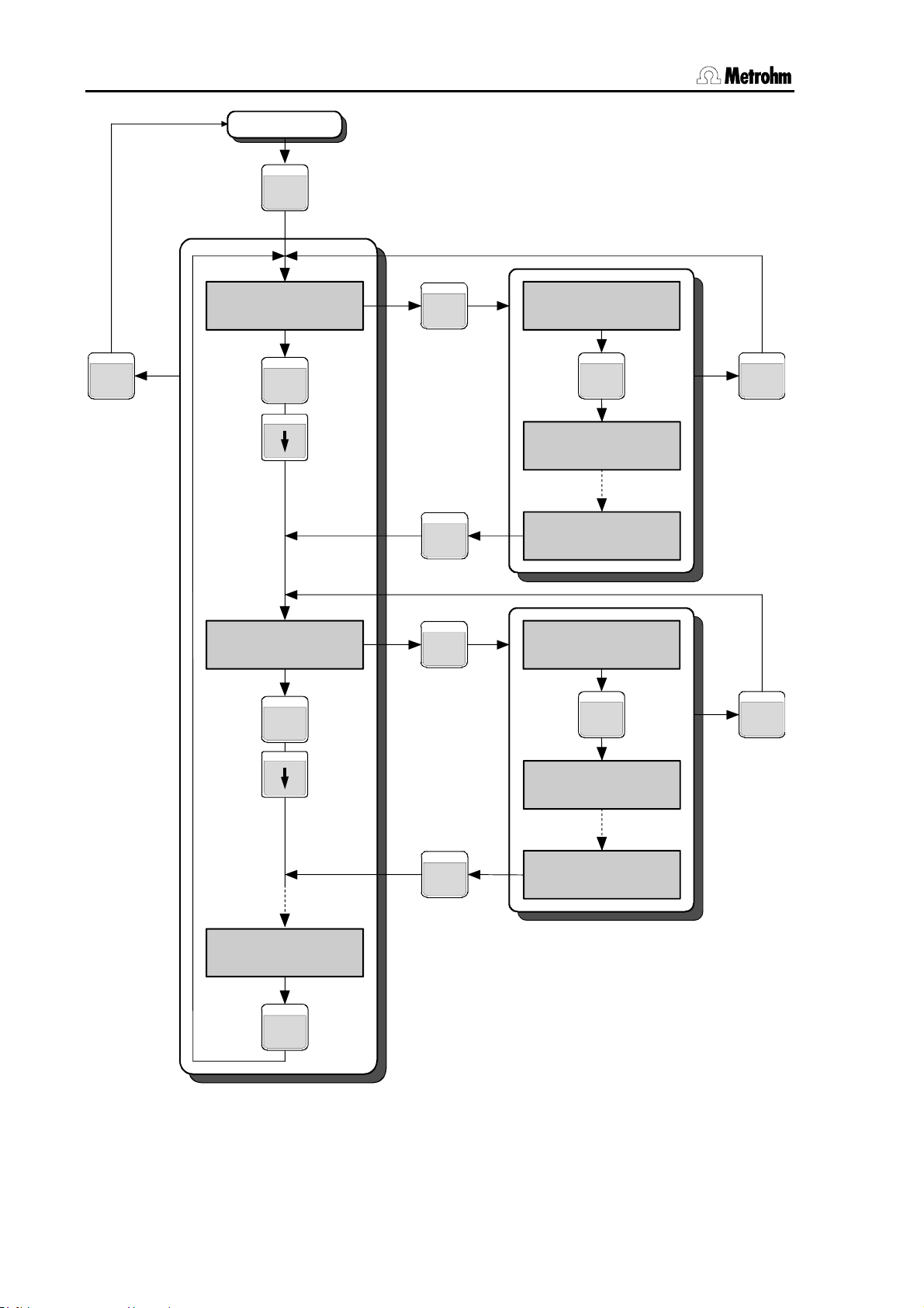
2.1 Operating principles
Normal state
KEY
QUIT
Kex title
>Submenu 1
KEY
Key title
>Submenu 2
KEY
ENTER
ENTER
ENTER
>Submenu 1
Inquiry 1
ENTER
>Submenu 1
Inquiry 2
>Submenu 1
Inquiry n
>Submenu 2
Inquiry 1
ENTER
QUIT
QUIT
Key title
>Submenu n
KEY
Fig. 2 Dialog arrangement
ENTER
>Submenu 2
Inquiry 2
>Submenu 2
Inquiry n
12 Metrohm 838 Advanced Sample Processor, Operation
Page 21
2.1 Operating principles
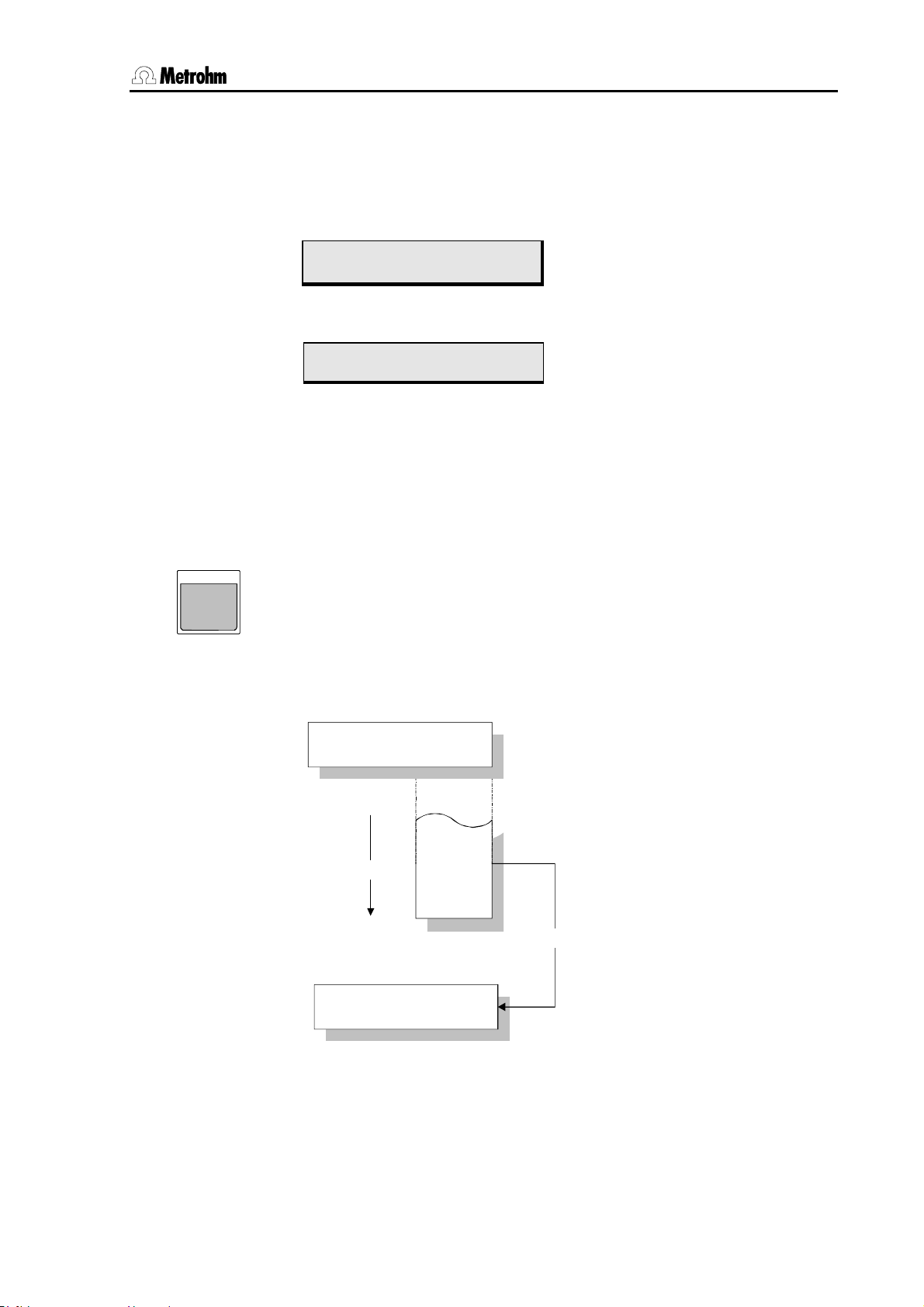
2.1.5 Data input
Input line
Either one or two parameters can be entered in a menu line or a sequence. A blinking block cursor indicates where a parameter can be
entered.
<Select> list
SELEC T
>stirring rates
stirrer tower 1 █ 3
Title line
Input line
Menu entry Cursor Parameter
>sample sequence
04 STIR █ T1 : 1 s
Command 1
st
parameter 2nd parameter
Title line
Input line
Switching between the parameters is carried out with the arrow keys
<> and <>. <ENTER> moves the cursor automatically to the
right, <QUIT> moves it to the left.
Data can usually be entered directly by the numerical keys of the keypad.
For entries marked by a colon the <SELECT> key can be used to dis-
play a selection of entries. This selection is cyclically arranged like a revolving drum.
Example:
>RS232 settings
baud rate: 9600
9600
<SELECT>
>RS232 settings
baud rate: 2400
4800
2400
1200
600
<ENTER>
Fig. 3 Selection list
Metrohm 838 Advanced Sample Processor, Operation 13
Page 22

2.1 Operating principles
2.1.6 Text input
The text editor can be used wherever provision is made for the entry of
a text.
Numbers can be entered directly via the keypad.
PRINT
<
ENDSEQ
The "<" or ">" keys open the text editor. With "<" an existing character
>
string is deleted and the text cursor moves to the left-hand end of the
.
*
input field. With ">" an existing character string is retained, the text cursor moves to the last character of the existing text.
A character string is displayed that consists of all the characters that
can be entered in alphabetic order. The currently selected character
always blinks (text cursor).
Character selection
The "<" and ">" keys move the character string made up of all the se-
lectable characters (upper and lower case letters, numbers and special
characters, arranged alphabetically) in the selected direction past the
text cursor. Pressing either of these keys once moves the character
string in the corresponding direction by one position. Rapid character
string movement is achieved by keeping the key pressed down.
Confirming character selection
ENTE R
The <ENTER> key appends the character currently under the text
cursor to the existing text line. When the complete width of the text input field has been filled the text input mode is exited and the text line is
accepted with <ENTER>.
RESET
CLEAR
Delete character
The <CLEAR> key deletes the last character of an existing text line.
The text cursor automatically moves one character to the left.
Ending text input
QUIT
<QUIT> exits the text input mode. The displayed text line can then be
accepted with <ENTER> or rejected by pressing <QUIT> a second
time.
14 Metrohm 838 Advanced Sample Processor, Operation
Page 23
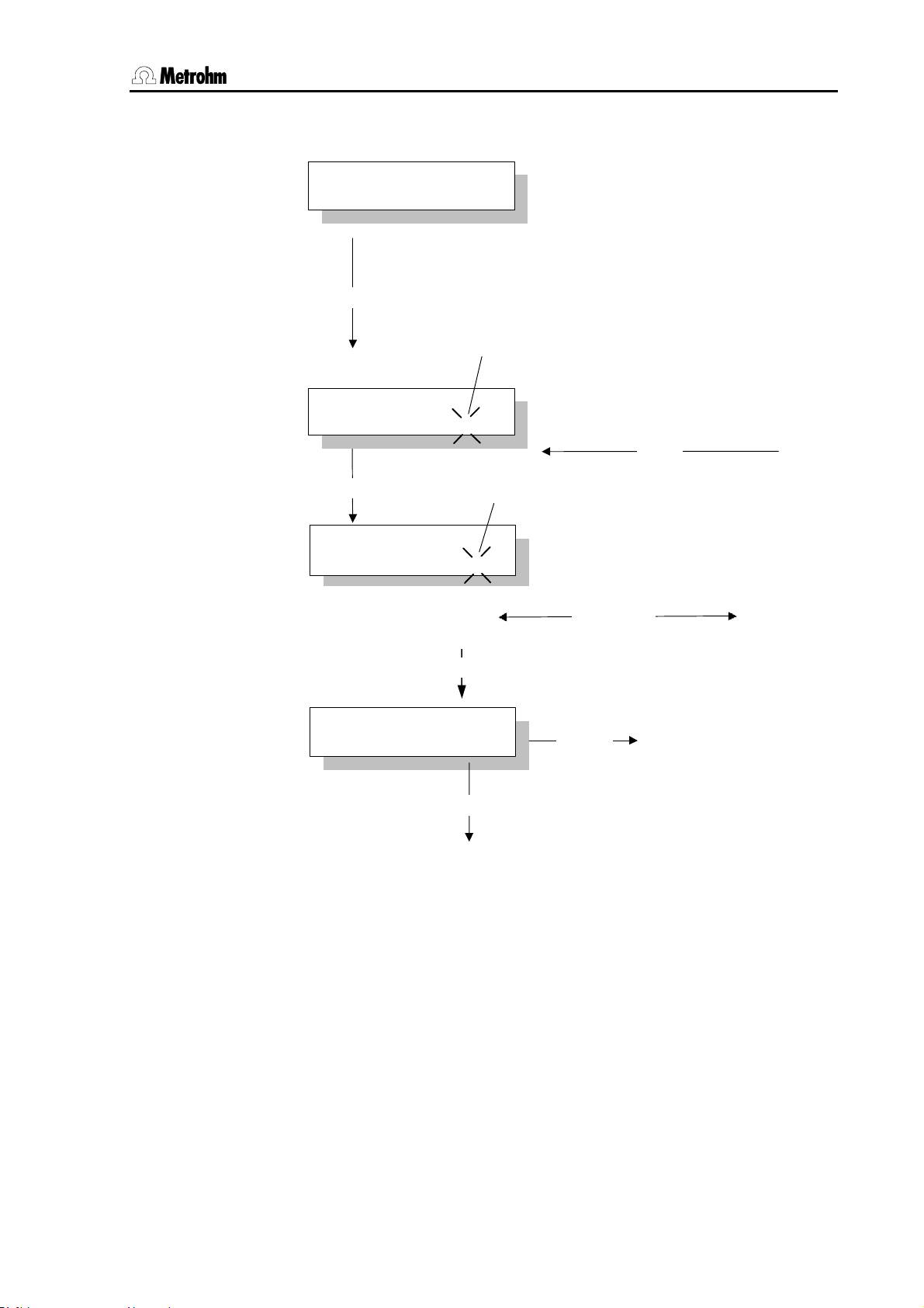
2.1 Operating principles
Arrangement:
>store method
method: ********
"<" or ">"
blinking text cursor
>store method
█
method:
<ENTER>
>store method
method:
>store method
method: Chloride
ABCDEFGHIJ...abcd...1234...*%&/()=...
█
DEFGHIJ...abcd...1234...*%&/()=...
CC
<QUIT>
<ENTER>
blinking text cursor
"<" or ">"
...<ENTER>...
<QUIT>
character chain
2x ">"
reject
accept
Fig. 4 Text input
The figure above shows how a character string can be entered, e.g. for
naming a method. Text input is concluded with <QUIT>. The whole of
the entered character string is then shown and can be accepted with
<ENTER> or rejected with <QUIT>.
Metrohm 838 Advanced Sample Processor, Operation 15
Page 24
2.2 Configuration
her l
l
2.2 Configuration
CONFIG
Main menu:
configuration
>auxiliaries
configuration
>tower 1
configuration
>rack definitions
configuration
>Dosing units
configuration
>RS232 settings
• Open submenu with <ENTER>
• Use <> or <> to move up and down by one
menu item
• Use <HOME> or <END> to move to the first or last
menu item
• Use <QUIT> to return to operating condition
2.2.1 Miscellaneous
configuration
>auxiliaries
>auxiliaries
dialog: english
Use <QUIT>
for next hig
eve
english, deutsch,
français, español
>auxiliaries
display contrast 3
0…3…7 0 = low contrast
>auxiliaries
beeper: ON
ON,OFF
>auxiliaries
external Start: off
on, off
Normally the Sample Processor takes over the complete run control for a
sample series as the "Master". This may be unwanted, particularly if an
automated system has been set up that includes instruments that are not
from Metrohm. This is why the Sample Processor can also be started from
any external instrument via the Remote interface.
With
external Start: ON the run sequences of the Sample Processor will
be started as soon as input line 7 is activated at the Remote interface (low
level).
Submenu for basic settings
Open the submenu with <ENTER>
Select dialog language
Set display contrast
7 = high contrast
Beep for warnings on or off
Switch on external start via Remote line
(Input 7)
16 Metrohm 838 Advanced Sample Processor, Operation
Page 25
2.2 Configuration
The run sequences of the Sample Processor will be stopped when input
line 6 is activated (low level). The technical details can be found in the
8.789.1033 Technical Reference of the Sample Processors.
>auxiliaries
>>running time meter
Shows the elapsed time
0…9999 h
Submenu for running time meter, open
with <ENTER>
>>running time meter
elapsed time 0.0 h
Warning limit for running time
meter
OFF, 0…9999 hours
>>running time meter
warning OFF h
The running time meter is used to support the regular maintenance of the Sample Processor. If a warning limit is entered then,
when this period has elapsed, a message will appear indicating
that maintenance is required.
>auxiliaries
device label
8 ASCII characters
Name of the instrument
for identification
>auxiliaries
program 5.838.0012
read only
Program version
Metrohm 838 Advanced Sample Processor, Operation 17
Page 26
2.2 Configuration
2.2.2 Tower settings
configuration
>tower 1
Submenu for basic settings for the tower
Open the submenu with <ENTER>
>tower 1
max. stroke path 125 mm
0…125…235 mm
Max. lift range for Lift 1
This max. stroke path setting is important for safety reasons. Correct entry
of this value can prevent, that i. e. an injection needle or tubing will be bent.
The working head cannot move any lower than the position entered here
(0 mm = upper stop of lift). Make these settings before you edit the rack
definitions.
>tower 1
min. beak. radius * mm
*, 1…100 mm * = any value
Sets the minimum required beaker radius for processing a sample
This is also a safety setting. In order to prevent a fully equipped, wide titration
head from trying to enter a narrow sample beaker a limit for the minimum
necessary beaker radius can be entered here. During a method sequence
the value entered here will be compared with the value given for the effective
beaker radius in the rack table before the lift is lowered and, if necessary, an
error message will be produced.
Entering * prevents a comparison from being made.
>tower 1
>>swing head 1
Submenu Swing Head
Open with <ENTER>
If a 786 Swing Head equipped with a robotic arm is mounted on the Sample
Processor then it is essential that the correct settings for the mounted robotic
arm are entered, as otherwise the instrument will not be able to position it
exactly.
Each of the following settings can be interactively defined with the LEARN
function. Press the <LEARN> key and then move the lift or robotic arm
with the arrow keys <> and <> or <> and <>. The set values
can be accepted with <ENTER> and corrected later.
For further explanations of the LEARN mode, see section 2.3.8.
Setting the rinsing height for external positions *
0…235 mm
)
>>swing head 1
rinse position 0 mm
Setting the swing height for external positions *
0…235 mm
)
>>swing head 1
shift position 0 mm
18 Metrohm 838 Advanced Sample Processor, Operation
Page 27
2.2 Configuration
Swing angle for external posi-
)
tion 1 *
Offset…84.00…max. angle+offset
>>swing head 1
external pos.1 117.00°
0° = points to rack center
The swing angle for the external positions is entered as an absolute angle. The input limits are defined by the offset of the Swing
Head drive (approx. 9°) and the set max. swing angle range.
Setting the working height for
external position 1 *
0…235 mm
)
>>swing head 1
work position1 0 mm
Swing angle for external position 2 *
… up to external pos. 4
* can be set with LEARN function
)
>>swing head 1
external pos.2 117.00°
Metrohm 838 Advanced Sample Processor, Operation 19
Page 28
2.2 Configuration
her l
l
2.2.3 Rackdefinitionen
configuration
>rack definitions
>rack definitions
>>recall rack
Use <QUIT>
for next hig
eve
In order to make a modification to the definition of a sample rack the rack
data must first be loaded. The data of the Metrohm standard racks is stored
under their ordering number.
>recall rack
name: 6.2041.450
10 ASCII characters
The <SELECT> key can be used to make a selection from the saved rack
data. The rack data is loaded with <ENTER>. The first selection to appear
is the rack name of the currently attached rack.
>recall rack
code 000001
000001…111111
The magnet code is used for the unambiguous identification of the rack. The
magnet code is recognized during the initialization of the rack. This is why
the <RACK> key should be pressed whenever a rack is changed.
For security reasons the max. stroke path should be set before modifications
of the lift positions are made, see section 2.2.1.
>recall rack
work position T1 0 mm
0…235 mm (in mm from upper stop point)
>recall rack
rinse position T1 0 mm
0…235 mm (in mm from upper stop point)
>recall rack
shift position T1 0 mm
0…235 mm (in mm from upper stop point)
>recall rack
special pos. T1 0 mm
0…235 mm (in mm from upper stop point)
>recall rack
beaker radius * mm
*, 1…100 mm * = any value
This setting is required for the check of the beaker radius, see p. 17.
Submenu for defining individual racks
Open the submenu with <ENTER>
Load rack definitions
Name of the rack to be loaded
Magnet code of the rack
See table on p. 65.
Working position for sample positions *)
Rinsing position for sample positions *)
Shifting position for sample positions *)
Special position for sample positions *)
Effective beaker radius for the sample
positions on the rack
20 Metrohm 838 Advanced Sample Processor, Operation
Page 29
2.2 Configuration
her l
l
>recall rack
beaker sensor: off
Tower, SwingH, off
Selection of the beaker sensor
Not implemented.
>recall rack
rack offset 0.00°
Correction for the rotation angle of the
sample rack *
)
-5.00…0.00…5.00°
)
*
All the above lift positions and the rack offset can be set by using the
<LEARN> function.
Special beaker positions
Use <QUIT>
for next hig
>>recall rack
>>>special positions
Submenu special beaker positions
Open with <ENTER>
Special beaker positions are predefined places on a sample rack that are not
treated as sample positions. They can be occupied by rinsing beakers or
eve
conditioning beakers and selectively addressed during a run sequence. Up
to 16 special beaker positions can be defined per rack. For each special
beaker the work position of the lift and the beaker radius can be set, see
above.
Selection of special beaker
1…16
Rack position of the special
beaker
etc. up to special beaker 16
>>>special positions
special beaker 1
>>special positions 1
rack position 0
0…number Pos.
0 = not defined
>rack definitions
>>store rack
Save rack definitions
In order to store modifications to the definition of a sample rack the submenu
>>store rack is selected.
>store rack
name: 6.2041.310
10 ASCII characters
Name of rack
With the <SELECT> key you can select one of the existing rack names. The
rack data is stored with <ENTER>. Any rack name can be used. The input
of any rack name can be made directly via the numerical keys or in the text
Metrohm 838 Advanced Sample Processor, Operation 21
Page 30
2.2 Configuration
input mode, see p. 14. Selection of the alphanumerical characters with the <
and > keys or <PRINT> and <RACK>.
>rack definitions
>>delete rack
Delete rack definitions
The submenu >>delete rack must be selected if a rack definition is to be
deleted.
>delete rack
name: 6.2041.310
Name of the rack
The <SELECT> key can be used to select one of the existing rack names.
<ENTER> confirms the selection. <QUIT> stops the deletion process.
Before the deletion a question appears.
>rack definitions
delete 6.2041.310 ?
<ENTER> confirms the deletion. <QUIT> stops the deletion process.
When the submenu '
data a request appears about saving the rack data.
>rack definitions
overwrite 6.2041.310 ?
>rack definitions' is exited without saving modified
Confirm the question (store the rack definitions) by pressing the
<ENTER> key. Reject storage with <QUIT>.
22 Metrohm 838 Advanced Sample Processor, Operation
Page 31

2.2 Configuration
her
l
l
2.2.4 Dosing units
Metrohm Exchange units (with 685 and 805 Dosimats as the dosing drive) and Dosing units for
the Dosino 700 and 800 systems can be used with the Sample Processors. The following settings are used for preparing the Dosing units (PREP function). The tubing dimensions (length
and diameter) are used for calculating the rinsing volumes.
If Exchange units are used then only the dosing and filling rate is effective (
max. rate).
configuration
>Dosing units
Submenu for the Dosing unit settings
Open the submenu with <ENTER>
Use <QUIT>
for next hig
eve
>Dosing units
Dosing unit 1
1…3
The Dosing unit selection must be confirmed with <ENTER>. It will then be
shown in the first menu line.
Selection of Dosing unit or dosing device
connection
>Dosing units 1
max. rate 1 160 ml/min
0.01…160 ml/min
Max. dosing and filling rate for Port 1
(depends on cylinder size)
>Dosing units 1
tube length 1 1000 mm
0…1000…30000 mm
Length of tubing at Dosino Port 1
>Dosing units 1
tube diameter 1 2 mm
0.1…2…20 mm
Diameter of tubing at Dosino Port 1
>Dosing units 1
max. rate 2 160 ml/min
0.01…160 ml/min
Max. dosing and filling rate for Port 2
(depends on cylinder size)
>Dosing units 1
........... to port 4
Input of tubing parameters for all four
ports of a Dosing unit.
Metrohm 838 Advanced Sample Processor, Operation 23
Page 32

2.2 Configuration
her l
l
2.2.5 RS232 settings
The correct settings of the interface parameters of the serial RS232 interface is essential for the
perfect functioning of data transmission to and from the Sample Processor. This includes the
control of the instrument by using a PC software such as «IC Net».
configuration
>RS232 settings
Submenu for serial interface settings
Open the submenu with <ENTER>
Use <QUIT>
for next hig
eve
>RS232 settings
baud rate: 9600
300,600,1200,
2400,4800,9600, 19200
Transmission rate
in baud
>RS232 settings
data bit: 8
7,8
Number of data bits
>RS232 settings
stop bit: 1
1,2
Number of stop bits
>RS232 settings
parity: none
even, odd,
none
Parity selection
>RS232 settings
handshake: HWs
HWs,SWchar,SWline,
none
Handshake selection
>RS232 settings
character set: IBM
IBM,HP,Epson,
Seiko,Citizen
Character set for printer and PC
(printer emulation)
For data transmission using personal computers you should select IBM.
>RS232 settings
RS control: ON
ON,OFF
Switch data reception on/off
If Remote control is switched off then no data will be received.
24 Metrohm 838 Advanced Sample Processor, Operation
Page 33

2.3 Composition of a method
2.3 Composition of a method
All the settings of the parameter menu form a method and can be
stored as such.
2.3.1 Run sequences and method parameters
PARAM
Main menu:
parameters
number of samples: rack
1…999,
rack,∗
Number of samples to be processed
rack = one sample rack rotation
∗ = infinite
In the rack setting all the sample positions of the current rack will be
processed (max. no. of rack positions minus number of special beakers), with only the positions occupied by sample beakers being
counted. It is important that the Sample Processor can recognize the
rack. This is only possible when the rack is in initial position. We recommend that each time a rack is changed the Sample Processor is
initialized with <RACK>.
parameters
>start sequence
parameters
>sample sequence
parameters
>final sequence
parameters
>changer settings
parameters
>stirring rate
parameters
>dosing unit def.
parameters
>timeout settings
parameters
>nanual stop
Open submenu with <ENTER>
Use <> or <> to move up and down by one menu
item
Use <HOME> or <END> to reach the first and last
menu item
Use <QUIT> to return to normal operating condition
Submenus:
In each of the submenus
>start sequence, >sample sequence and >final sequence up to 99
command lines can be entered as a run sequence. The commands can be entered directly via
the keypad. The command keys on the right-hand side of the keypad are available.
parameters
>start sequence
Commands for the start sequence of the sample series
Open the submenu with <ENTER>
The start sequence is carried out once at the start of a sample series.
Metrohm 838 Advanced Sample Processor, Operation 25
Page 34

2.3 Composition of a method
parameters
>sample sequence
parameters
>final sequence
Series operating
<START>
Commands for the processing of each sample
Open the submenu with <ENTER>
The sample sequence is carried out when each individual sample in
a sample series is processed.
Commands for the final sequence of the sample series
Open the submenu with <ENTER>
The final sequence is carried out once at the end of a sample series.
For example, it can be used to move to a rinsing or conditioning
beaker.
number
of samples
start sequence final sequence
sample sequence
normal state
Fig. 5 Sample series
Creating methods
In principle the same input rules apply for creating run sequences as for
manual operation, i. e. after selecting a command and entering the
necessary parameters the entry is confirmed with <ENTER>. The next
command line is then selected and a new command can be entered.
For more comfortable parameter input the LEARN function is available
for certain commands. It can be used to accept direct values that are
set when a single command is carried out manually. Please refer to p.
Fehler! Textmarke nicht definiert. for details.
The TRACE function can be used to execute each entered command
line individually in the editing mode. See p. 33.
Navigation in a sequence is the same as in other menus. In addition,
the <INSERT> and <DELETE> keys are available.
<INSERT> inserts a new command line above the current line of a
sequence. It is automatically occupied with the NOP command, which
has no function. The following lines move downward by one position.
<DELETE> deletes the current line of a sequence. The following lines
move upward by one position.
26 Metrohm 838 Advanced Sample Processor, Operation
Page 35
2.3 Composition of a method
2.3.2 Sample Processor settings
parameters
>changer settings
>changer settings
rack name: *
*,10 ASCII characters * = no particular rack
With this setting the user can be forced to use a particular rack for the selected method. If this is not required then
>changer settings
lift rate T1 25 mm/s
5…25 mm/s
>changer settings
shift rate 20°/s
3…20
>changer settings
shift direction: auto.
+,–,auto. auto. = the Sample Processor selects the shortest
>changer settings
rotat. increment: 5.00°
0.00…5.00…270.00°
>changer settings
swing rate T1 55°/s
10…55
Submenu for setting the Sample Processor functions
Open the submenu with <ENTER>
The sample rack assigned to the method
rack name: * must be selected.
Vertical movement rate of the lift
Speed at which the rack rotates
in degrees per second
Direction of rotation of the sample rack
path for the rotation itself.
Increment angle for the command
MOVE +/-rotate
Swing rate of the robotic arm in degrees/second
>changer settings
swing increment 10.00°
0.00…10.00…180
>changer settings
on beaker error: MOVE
Increment angle for the command
MOVE +/-swing
Definition of reaction if beaker is missing
Not implemented.
Metrohm 838 Advanced Sample Processor, Operation 27
Page 36
2.3 Composition of a method
2.3.3 Stirrer settings
parameters
>stirring rates
>stirring rates
stirrer tower 1 3
1…3…15
>stirring rates
stirrer MSB1 3
1…3…15
>stirring rates
stirrer MSB2 3
1…3…15
>stirring rates
stirrer MSB3 3
1…3…15
Submenu for the stirrer settings
Open the submenu with <ENTER>
Stirring speed of the stirrer at the tower
(stirrer models 802, 741, 722)
Stirring speed of MSB stirrer 1
(stirrer models 801, 804)
Stirring speed of MSB stirrer 2
(stirrer models 801, 804)
Stirring speed of MSB stirrer 3
(stirrer models 801, 804)
28 Metrohm 838 Advanced Sample Processor, Operation
Page 37

2.3 Composition of a method
2.3.4 Dosing drive settings
Both Dosinos (models 700 and 800, with Dosing units) and Dosimats (models 685 and 805,
with exchange units) can be used as dosing drives on an Advanced Sample Processor. However, free assignment of the ports for the various functions is only possible with Dosinos.
parameters
>Dosing unit def.
Submenu for setting the Dosing units
Open the submenu with <ENTER>
>Dosing unit def.
dosing drive 1
1…3
Selection of the dosing device, or the
connection
After entering the connection of the dosing device (see Installation instructions 8.1303) and confirming with <ENTER> the settings for the selected
dosing device should then be made.
>dosing drive 1
dos.rate max. mL/min
0.01…160 mL/min, max.
Set the dosing rate
The maximum possible dosing rate depends on the size of the dosing cylinder (rule of thumb: cylinder volume x 3.3).
>dosing drive 1
fill.rate max. mL/min
0.01…160 ml/min, max.
Set the filling rate
The maximum possible filling rate depends on the size of the dosing cylinder
(rule of thumb: cylinder volume x 3.3).
The following entries only apply to 700/800 Dosinos. Details about Dosinos
and Dosing units can be found on p. 54ff.
>dosing drive 1
dosing port 1
1…4
Define standard dosing port 1
>dosing drive 1
dosing 2 port 3
1…4
Define standard dosing port 2
>dosing drive 1
filling port 2
1…2…4
Define standard filling port
>dosing drive 1
rinsing port 2
1…2…4
Define standard rinsing inlet (if Dosing
unit is exchanged)
>dosing drive 1
preparation port 1
1…4
Define standard outlet for the preparation cycle
Metrohm 838 Advanced Sample Processor, Operation 29
Page 38

2.3 Composition of a method
>dosing drive 1
drain port 4
1…4
Define standard air inlet for emptying the
Dosing unit
>dosing drive 1
cock direction: auto
auto
not over
desc.
asc.
>dosing drive 1
not over port 4
1…4 (see above)
Direction of rotation of Dosino stopcock
= cock direction according to shortest path
= never turn beyond port given below
= cock rotation always in descending direction
= cock rotation always in ascending direction
Protected port, that it not to be moved
over during a stopcock rotation
2.3.5 Behavior during timeout
Metrohm Sample Processors are designed to communicate with other
instruments. In particular, this includes the coordination between the
Sample Processor and devices connected to it. In the method sequence the SCAN command can be used to check whether an instrument is ready or to ask for an acknowledgement after a measurement
has been made. However, it may happen sometimes that problems occur during a determination run and that the expected signal from the
connected instrument is not received. This is known as a timeout.
This means that it is possible to define a maximum waiting time that will
always be allowed to elapse if a timeout occurs. In addition, the behavior of the Sample Processor when this waiting period has elapsed
(SCAN timeout) can also be defined.
parameters
>timeout settings
>timeout settings
SCAN timeout: OFF min
off,0…999 min
When the waiting time has elapsed the function defined below will be carried
out.
>timeout settings
on SCAN timeout: error
error,continue
If
sage will be shown. Otherwise the sequence will be continued.
Submenu for behavior if a SCAN timeout occurs
Open the submenu with <ENTER>
Waiting time if a SCAN timeout occurs
Behavior if SCAN timeout occurs
error is set then the run sequence will be interrupted and an error mes-
30 Metrohm 838 Advanced Sample Processor, Operation
Page 39

2.3 Composition of a method
2.3.6 Manual stop options
The following settings can make a great contribution to the comfortable
operation of the Sample Processor. A definition is made of what is to
happen when the <STOP> key is pressed. This could be a normal
manual cancellation of a running method, or an emergency stop of the
complete system. Depending on the arrangement of the automated
system and the type of application, it can be laid down in detail how the
individual instrument components and connected instruments are to
react when the <STOP> key is pressed.
parameters
>manual stop options
>manual stop
CTL Rmt: **************
14 bit (1,0 or ∗)
Connected peripheral devices can be stopped automatically. The 14 signal
lines of the Remote interface can be set as required, see also p. 68ff.
>manual stop
CTL RS232:
14 ASCII characters default value '&M;$S' (= stops a Metrohm device)
Connected peripheral devices (e.g. Metrohm devices) can be stopped
automatically. Any character string can be transmitted. For details of the serial RS232 interface see "Technical Reference".
>manual stop
PERISTALT: cont.
cont., off, on (cont. = retain condition)
>manual stop
PUMP: cont.
cont., off, on (cont. = retain condition)
This setting applies to both pump connectors.
>manual stop
STIR T1: cont.
cont., off, on (cont. = retain condition)
>manual stop
STIR MSB1: cont.
cont., off, on (cont. = retain condition)
>manual stop
STIR MSB2: cont.
cont., off, on (cont. = retain condition)
>manual stop
STIR MSB3: cont.
cont., off, on (cont. = retain condition)
Submenu for reaction after manual stop
Open the submenu with <ENTER>
Set signal lines of the Remote interface
Command or character string, for output
via the RS232 interface
Switches the peristaltic pump
Switches the pump connectors
Switches the stirrer at the tower
Switches the stirrer at MSB connection 1
Switches the stirrer at MSB connection 2
Switches the stirrer at MSB connection 3
Metrohm 838 Advanced Sample Processor, Operation 31
Page 40

2.3 Composition of a method
2.3.7 Programming of sequences
INSERT
DELETE
The creation of sequences is done in the submenus
'>sample sequence' and '>final sequence', which are accessible via the
'>start sequence',
parameter menu.
Each sequence is organized in lines. In each line, the commands that
are on the numerical keypad as alternate functions can be used to enter
commands. After selecting a command and entering the necessary
data, the entry is accepted with <ENTER>. The line number is visible in
the display. 99 lines per sequence are possible.
Navigation in a sequence is accomplished as in the other menus. In
addition the <INSERT> and <DELETE> keys can be used.
<INSERT> adds a new command line above the current line in a
sequence. It is automatically occupied by the "NOP" command that has
no function. The following lines are shifted one line downwards.
<DELETE> deletes the current line in a sequence. The following lines
are shifted one line upwards.
The "LEARN" mode is available for the easy entry of parameters.
Furthermore the "TRACE" function can be used to execute every command line step by step.
2.3.8 LEARN mode
LEARN
HOLD
When editing a method, the parameters of a command are most easily
determined experimentally, i.e. by manual execution, and it is for this
reason that certain commands are "teachable". The LEARN function
makes the manual execution of particular changer commands possible
during the editing of a sequence. The resulting parameters (for example, the lift position or the status of the input lines) can be taken over in
the current command line. The LEARN function can be used repetitively. When times or volumes are "learned", the repetitive values are
added up.
Procedure for creating a method
• Enter a command or select an existing command line.
• Press the <LEARN> key.
"LEARN" LED goes out, edit next command line.
− Function is started, "LEARN" LED lights up.
− Press the <LEARN> key.
− Function is stopped, "LEARN" LED blinks.
− With the <ENTER> key, accept the value
(or re-start the LEARN function).
Die LEARN-Funktion steht für folgende Befehle zur Verfügung:
32 Metrohm 838 Advanced Sample Processor, Operation
Page 41

2.3 Composition of a method
Command Teachable parameter Mode of function
LIFT
PERISTALT
PUMP
WAIT
SCN Rm
SCN RS
2.3.9 TRACE-Funktion
The "TRACE" function is a valuable aid for operating through an entire
START
sequence or method (or parts thereof) for test purposes. Every command line in a sequence can be executed directly by pressing the
<START> key. Upon completion of the action the next command line
is displayed.
Tracing can be executed immediately after entry of a sequence line or
at any time after opening the parameter menu and selecting a sequence.
Lift position in mm
Pump time in sec
Pump time in sec
Waiting time in sec
absolute
additive
additive
additive
Status of the 8 remote lines "live" value
Character sequence received
"live" value
Metrohm 838 Advanced Sample Processor, Operation 33
Page 42

2.4 Commands
2.4 Commands
2.4.1 Sample Processor commands
The following commands can be programmed to form a sequence.
Most of them are also available in manual operation.
The following list applies to the programming of run sequences.
SAMPLE
SAMPL E
7
Beispiele:
>start sequence
1 SAMPLE: = 1
=,+,–
1…999
Set current sample position
1st parameter: function
nd
2
parameter: value
With the SAMPLE command you can define which sample (beaker
position on the rack) is to be regarded as being the current sample position (SAMPLE = X). This is stored in a run variable and can, for example, be altered in a sample sequence (SAMPLE + X or SAMPLE – X) in
order to selectively control a sample series.
SAMPLE: = 5
SAMPLE: + 2
SAMPLE: - 1
Sets SAMPLE variable to 5, or first sample in the series to rack position 5
Increases SAMPLE variable by 2
Decreases SAMPLE variable by 1
If in a sample sequence the SAMPLE command is not programmed,
then each run will automatically increases the SAMPLE variable by 1.
The SAMPLE command does not have to be used for simple applications. Unless anything to the contrary is required, the first sample in a
series will automatically be assumed to be in rack position 1. This is
why we recommend that special beakers are not placed on the first
rack positions, but are set on the highest rack positions.
Under manual operation the <SAMPLE> key can be used before the
start of a sample series to define the position of the first sample, provided that this has not already been defined in the method itself.
If a particular arrangement of sample beakers is always to be used for a
certain application then the position of the first beaker can be defined in
the start sequence with
SAMPLE = X and this setting can be stored in the
particular method.
The value of the SAMPLE variable remains at the end of a sample series. It is only reset to 1 when the instrument is switched on, when a
RESET command (<RESET> key) is executed or after a RACK command (<RACK> key or in in a method run).
34 Metrohm 838 Advanced Sample Processor, Operation
Page 43

MOVE
MOVE
8
2.4 Commands
>sample sequence
2 MOVE 1 : sample
1,2
sample,
ext.1…ext.4
spec.1…16
prev., next
+swing, -swing
+rotate, -rotate
1…999
+/-1…999
Position beaker / Swing robotic
arm
1st parameter: tower (Tower 2 not possible)
2nd parameter: position
With the MOVE command rack positions are moved to, i.e. the turntable rotates until the sample rack is positioned so that the selected rack
position is placed in front of Tower 1 or 2 (if present). If no 786 Swing
Head is mounted then only the rack positions of a 1-row rack can be
accessed.
With 786 Swing Head
If a 786 Swing Head is mounted then any rack positions can be moved
to. The angle of rotation of the rack is then compared with the swing
angle of the robotic arm and corrected accordingly.
Beispiele:
MOVE 1 sample
MOVE 1 ext.1
MOVE 1 spec.1
MOVE 1 5
MOVE 1 next
MOVE 1 +2
Parameters
In addition to a rack position, the robotic arm of a 786 Swing Head can
also be swung to any external position. The selectable external positions ext.1 to ext.4 can be defined in the whole swing range from 0° up
to the maximum swing angle of the robotic arm. For example, this
means that it is possible to move to a titration cell located beside the
sample rack.
Moves sample beaker (defined by SAMPLE variable) in front of the tower
Moves robotic arm to external position 1
Moves special beaker 1 in front of the tower
Moves rack position 5 in front of the tower (absolute positioning)
Moves next highest rack position in front of the tower
Depending on the current sample position (SAMPLE variable), moves the next position
but one in front of the tower (relative positioning)
sample – rack position corresponding to the current value of the SAMPLE variable, see also p. Fehler! Textmarke nicht definiert..
ext.1 to 4 – predefined angle positions of the robotic arm. These are
defined in the configuration of a tower, see also p. 17.
next, prev. – from the current rack position the next highest (next) or
the next lowest (prev.) will be moved to. Special beaker positions will be
skipped. If MOVE next is used at the highest rack position then the
move will be made to position 1. If MOVE prev. is used at rack position
1 then the highest possible position will be moved to.
spec.1 bis 16 – reserved special beaker positions on the sample rack.
These are defined in the rack configuration, see also p. 20.
Metrohm 838 Advanced Sample Processor, Operation 35
Page 44

2.4 Commands
+swing, -swing – moves the robotic arm by a certain increment angle.
The sign shows the swing direction. The value of the angle is predefined under
Parameter >changer settings.
+rotate, -rotate – moves the rack by a certain increment angle. The
sign shows the rotation direction. The value of the angle is predefined
under
Parameter >changer settings.
absolute positioning – the numbered rack position will always be
moved to, even when this is a reserved special beaker position.
relative positioning – If a numerical rack position is given with a positive or negative sign then the selected rack position will always be relative to the value of the SAMPLE variable, i.e. to the current sample
position.
Remarks
In a method sequence a MOVE command will move the lift (or both
lifts) automatically to the shifting position.
After execution of the functions +/-swing or +/-rotate the lift can be
moved without restrictions. No defined rack position is required. Thus it
is possible to cause damages if the lift is lowered without precautions.
These functions must be used with great care.
LIFT
LIFT
9
Beispiele:
LIFT: 1: work
LIFT: 1: rinse
LIFT: 1: shift
LIFT: 1: special
LIFT: 1: rest
LIFT: 1: 100 mm
The direction of rotation is normally selected automatically by the Sample Processor. In the parameter menu under
>changer settings the di-
rection and speed of rotation can be defined specifically for particular
methods.
>sample sequence
3 LIFT: 1: rest mm
1,2,∗
work,
rinse, shift,
special, rest,
0…235 mm
Lift positioning
1st parameter: tower (Tower 2 not possible)
2nd parameter: position
Raises or lowers the lift to a defined position.
Moves the lift to working position
Moves the lift to rinsing position
Moves the lift to shifting position
Moves the lift to special position
Moves the lift to uppermost position (0 mm)
Moves the lift to position 100 mm
Working, rinsing, shifting and special positions are defined specifically
for each rack in the configuration menu under
>rack definitions (see
36 Metrohm 838 Advanced Sample Processor, Operation
Page 45

2.4 Commands
p. 20). The rest position is the zero position (0 mm) of the particular lift,
i.e. its upper stop.
The lift speed can be set in the parameter menu under
changer settings or altered in a sequence with the appropriate DEF
>sample
command.
Each lift can be positioned with an accuracy of one millimeter. The
LEARN function is available for this (see p. 70).
Metrohm 838 Advanced Sample Processor, Operation 37
Page 46

2.4 Commands
2.4.2 Switching components
Pumps and stirrers can be switched as required, either together or
separately. They work independently and can be operated at the same
time as other functions are being carried out.
PERISTALT
PUMP
4
>sample sequence
4 PERISTALT: on s 3
on,off,1...999
-15…-1, 1…3…15
Pump control
1st parameter: status or duration in s
nd
2
parameter: pump rate and direction
With the PERISTALT command the peristaltic pump can be controlled.
The first parameter switches the peristaltic pump on or off. Alternatively
a particular pump duration (in seconds) can be set.
The second parameter sets the pump rate in 15 steps. The signed
value (+ or –) also defines the pump direction. If a negative signed
pump rate is set, the roller head of the pump drive revolves counterclockwise, otherwise it revolves in clockwise direction.
PUMP
EXT
0
The LEARN mode is very useful for determining the optimal pump time
(see p. 71).
>sample sequence
4 PUMP 1.1 : 1 s
1.1,1.2 1…999 s,
1.∗,2.∗ on,off
Switching the pump connectors
1st parameter: select pump connector
nd
2
parameter: status or duration
With the PUMP command one or both pump connectors (16 V, DC) on
the rear side of the tower can be controlled separately. The first parameter selects the connector.
Syntax Of the 1
1.* affects both pump connectors (
st
parameter: tower.pump
tower 2 not possible)
The connectors can be switched on or off individually or be activated for
a particular duration.
The LEARN mode is very useful for determining the optimal pump time
(see p. 71).
38 Metrohm 838 Advanced Sample Processor, Operation
Page 47

STIR
.
STIR
5
2.4 Commands
>sample sequence
5 STIR T1 : 1 s
T1, T2,T*,
MSB1…3, MSB*, ∗ ON,OFF
1…999 s
Stirrer control
1st parameter: stirrer selection
nd
2
parameter: status, duration
With the STIR command up to 4 stirrers can be controlled separately.
The first parameter selects the stirrer. With
STIR * all the stirrers can be
switched at the same time .
Selecting a stirrer
T1, T2, T* Stirrer connections as Tower 1 and 2 respectively (stirrer
models 802 / 722 / 741),
* = both connections on the tow-
ers. T2 not possible.
MSB1…3 Stirrer/Dosing device connectors in the chassis of the Sam-
ple Processor (stirrer models 801 / 803 / 804),
MSB*= all
stirrers connected to an MSB socket.
* all stirrers
The stirrers can be switched on or off selectively, or operated for a particular time.
In the parameter menu under
vidual stirrer can be defined for a particular method.
2.4.3 Dosing drive control
Connected dosing devices can be controlled separately or all at the
same time . Simultaneous addition of the same volumes or simultaneous filling of the connected dosing devices is also possible (Example:
DOS *.2 fill = fill all dosing devices via port 2).
DOS
DOS
6
>sample sequence
6 DOS 1.* : 1 ml
*.*, 1.*…3.4
fill,release, prepar
empty, eject, endVol,
compen., port,
±0.001…1…±999.999 ml
The DOS command is used for controlling Dosimats and Dosinos. Up
to 3 Dosinos or Dosimats can be addressed individually or simultaneously via the MSB bus control.
>stirring rates the speed of each indi-
Dosing device control
1st parameter: dosing device and port selection
nd
2
parameter: selects function/enters volume
The 1st parameter selects the dosing device and the corresponding
dosing port, at which the required function is to be carried out. If '*' is
entered then the default port for the corresponding function will be used
(e.g. dosing port = 1, filling port = 2, etc.).
Metrohm 838 Advanced Sample Processor, Operation 39
Page 48

2.4 Commands
Please note
After dosing the Sample Processor will not automatically fill the
dosing cylinder. If required, this can be programmed with the command
DOS: 1.* : fill, see below.
It is possible to enter the volume to be added directly as the 2
nd
parameter or to carry out specific functions of a Dosino. Negative volumes
can also be added, i.e. a certain volume can be aspirated and then
ejected again (pipetting). The minus sign is entered with the <*> key.
The functions listed below are used for complex liquid handling tasks
such as pipetting.
Dosing functions:
fill Fills the Dosimat and Dosino cylinder.
release Prepares the Dosimat or Dosino for changing the Ex-
change/Dosing unit. The dosing cylinder is filled via the
rinse port. The stopcock is turned to the exchange position (Port 2).
prepar. Preparation cycle (PREP) for Dosinos. All tubing is rinsed
and filled completely.
empty Tubing system and Dosino cylinder are emptied.
eject Complete Dosino cylinder contents are ejected.
endVol Ejects the cylinder content to the max. volume mark.
compen. Cancels the mechanical play between the dosing piston
and spindle.
In the parameter menu under
>Dosing unit def. the port assignments
of the Dosinos as well as the dosing and filling rates can be defined for
specific methods.
More details about Dosino commands are given on p. 60ff.
The Sample Processor automatically recognizes whether a Dosimat or
a Dosino is connected.
40 Metrohm 838 Advanced Sample Processor, Operation
Page 49

2.4 Commands
2.4.4 Communication commands
The coordination of external instruments or the explicit triggering of
functions is possible via both the Remote interface and the serial RS232
interface. The interfaces can be scanned for particular signal patterns or
incoming data strings. In return, individual signal lines can be set or any
character strings (as control commands) can be transmitted to connected instruments.
SCAN
SCAN
1
>sample sequence
7 SCN:Rm : Ready1
Rm,RS Ready1
End1
End2
Wait1
Pump1 ?
Pump2 ?
Pump* ?
8 Bit (1,0 or ∗)
Wait2
Wait*
Scans the Remote
interface
= Device 1 ready
= EOD impulse device 1
= EOD impulse device 2
= Wait for Input2 to be set
(e.g. by 797 VA Computrace)
= Wait for Input4 to be set
= Wait for Input2 and Input4 to be set
= Wait until pump 1 is running
= Wait until pump 2 is running
= Wait until pump 1 and 2 are running
any 8-bit binary pattern
In a sequence the SCN:Rm command will halt the run sequence until
the predefined signal pattern has been received.
Predefined binary patterns are available; these can be selected via
simple names (e.g.
Ready describes a statically set Ready line (Output 0) of a connected
Metrohm instrument.
Ready1 or End2).
End stands for a pulsed signal, e.g. EOD (=End of
Determination, Output line 3).
Setting special binary patterns allows the flexible monitoring of connected instruments. The following applies:
Example:
0 = line inactive
1 = line active
* = any line condition
00000001 = input line 0 is active = Device 1: Ready1
With the LEARN function the binary patterns (=line conditions) can be
adopted interactively (see p. 71).
Metrohm 838 Advanced Sample Processor, Operation 41
Page 50

2.4 Commands
SCAN
1
>Sample sequence
8 SCN:RS
Rm,RS
default value: ∗R"
14 ASCII characters
Scanning the RS232 interface
= scan "Ready" status message
any data string with 14 characters
In a sequence the SCN:RS command will halt the method sequence
until the predefined data string (up to 14 characters) has been received
via the serial RS232 interface. Incoming data is checked character by
character.
Make sure that the transmission parameters of the RS232 interface are
identical with those of the connected device (see configuration menu
>RS232 settings, p. 23).
Any letters, numbers and special characters can be selected from the
character set of the Sample Processor. '∗' can be set as wild card for
any character string. (If '∗' is to be interpreted as an ASCII character
then '∗∗' must be used.) A wild card can be set within a character string.
When the first part of the character string has been recognized correctly
then a search will be made for the first appearance of the character
standing after '∗'. In this case the comparison will be made with the
second part of the character string.
Details of the CTL command are given below.
With the LEARN function transmitted data (=character strings) can be
adopted interactively (see p. 71).
42 Metrohm 838 Advanced Sample Processor, Operation
Page 51

CTL
CTRL
2
2.4 Commands
>sample sequence
9 CTL:Rm START Device1
Rm,RS
INIT 732/819
PROG R/S 1
PROG R/S 2
PUMP R/S 1
FILL A 1
INJECT A 1
FILL B/STEP 1
INJECT B 1
ZERO 1
PUMP 833 on
PUMP 833 off
STEP MSM 833
14 Bit (1,0 or ∗)
************1
Setting the Remote lines
INIT
initializes all Remote lines
initializes the Remote lines of 732/819
starts/stops the time program of 732/819-1
starts/stops the time program of 732/819-2
starts/stops IC Pumpe 818/1
switches valve A of 733/820/1 to "Fill"
switches valve A of 733/820/1 to "Inject"
switches valve B of 733/820/1 to "Fill"
switches valve B of 733/820/1 to "Inject"
activates autozero of 732/819
start pump 833
stops pump 833
advances suppressor module 833
= any binary pattern with 14 bit
start/advance device1 (e. g. 797 VA Computrace)
The CTL:Rm command is used for controlling external devices via the
Remote interface. It sets defined line conditions or transmits impulses
(200 ms) via the 14 Remote output lines.
Predefined binary patterns are available; these can be selected via
simple names (e.g.
PROG R/S 1 starts e. g. the time program of a connected IC detector.
PUMP 833 on or FILL A 1).
Setting special binary patterns allows the flexible monitoring of connected instruments. The following applies
0 = line inactive
1 = line active
∗ = retain line condition
Example:
************1* = Output line 1 active = start pump 833
Metrohm 838 Advanced Sample Processor, Operation 43
Page 52

2.4 Commands
CTRL
2
>sample sequence
10 CTL:RS
Rm,RS
default value: M;$G
14 ASCII characters
Data transmission via serial interface
= starts Metrohm instrument in current mode
any character string with 14 characters
Data (=character strings) can be transmitted to connected devices via
the serial RS232 interface.
Make sure that the transmission parameters of the RS232 interface are
identical with those of the connected device (see configuration menu
>RS232 settings, p.23).
Any letters, numbers and special characters can be selected from the
character set of the Advanced Sample Processor.
This function is primarily suitable for instruments that understand the
Metrohm Remote language. These can be controlled with so-called
triggers.
The most important of these are:
&M;$G Go, starts instrument in current mode
&M;$S Stop, stops device
&M;$H Hold, interrupts determination
&M;$C Continue, restarts determination
Switching on the AutoInfo status messages (e.g. in a start sequence)
can be carried out with the following Remote commands:
&Se.A.T.R"ON" Status message at "Ready" condition
&Se.A.T.F"ON" Status message at end of a determination
&Se.A.T.S"ON" Status message at manual Stop
&Se.A.T.G"ON" Status message at start of a method
&Se.A.T.E"ON" Status message at error condition
Logically the corresponding AutoInfo messages should be switched
off again in a final sequence (
..."OFF").
Detailed information about the syntax of the Remote language can be
found in the Instructions for Use of your Metrohm instrument.
For communication with instruments from other manufacturers or a
computer please conform with their syntax and conventions.
44 Metrohm 838 Advanced Sample Processor, Operation
Page 53

2.4 Commands
2.4.5 Auxiliary commands
WAIT
WAI T
>sample sequence
11 WAIT: pause 1 s
pause, runtime
0…1…9999 s
The WAIT command is used for setting a particular waiting time or for
waiting until a particular time (run time) in a run sequence.
pause is selected then the method run will be interrupted for the en-
If
tered duration (in seconds).
runtime is selected then the method run will be interrupted until the
If
selected running time (seconds counter) has been reached. The running time (in seconds) always starts at the beginning of an individual
sequence, i.e. start sequence, sample sequence or final sequence. If
the running time of the sequence has already been reached or exceed
when the WAIT command is executed then the method will be continued immediately.
Waiting time
RACK
RACK
*
>
>Sample sequence
12 RACK
Initialize rack
The rack turns to the starting position, i.e. the lift (or both lifts) move
upward to the rest position and the rack is rotated to the initial position.
The rack code is read off and the SAMPLE variable (position of the current sample) reset to 1. The RACK command should only be used in a
final sequence.
Metrohm 838 Advanced Sample Processor, Operation 45
Page 54
2.5 Managing methods
l
2.5 Managing methods
USER
METHOD
2.5.1 User-defined methods
Main menu:
methods
>recall method
methods
>store method
methods
>delete method
methods
>recall method
Use <QUIT> to
return to norma
operating
condition.
>recall method
name: ********
8 ASCII characters
All the stored methods can be selected with <SELECT>. If an "empty"
method is to be loaded then the method
<CLEAR>. This deletes the current working memory for methods.
methods
>store method
>store method
name: ********
8 ASCII characters
The text input mode is activated with '<' or '>' in order to be able to enter
your chosen method name (see p. 14).
methods
>delete method
>delete method
name: ********
8 ASCII characters
>delete method
delete ******** ?
Open submenu with <ENTER>
Use <> or <> up or down by one menu item
Use <HOME> or <END> to reach the first and last
menu items
Dialog for loading methods
Open the dialog with <ENTER>
Select method
******** can be selected with
Dialog for saving methods
Open the dialog with <ENTER>
Define method name
Dialog for deleting methods
Open the dialog with <ENTER>
Select method
Confirm with <ENTER>
Cancel with <QUIT>
46 Metrohm 838 Advanced Sample Processor, Operation
Page 55

2.5 Managing methods
2.5.2 POWERUP method
When the Sample Processor is switched on the sample rack and the
lifts move to their initial positions. This means that electrodes may also
be removed from the conditioning beaker. In order to re-immerse them
in the conditioning beaker you can use the POWERUP method. This
method is automatically started when the Sample Processor is switched
on and the initialization of the instrument is finished.
Create a method which contains a command sequence that is to be
processed when the Sample Processor is switched on. Save this
method under the name POWERUP (see p. 46).
Metrohm 838 Advanced Sample Processor, Operation 47
Page 56

2.6 Run control
2.6 Run control
With <START> you can start a method from the normal operating
START
STOP
condition. If no manual intervention is made, or if no unexpected error
occurs, the sample series will be processed correctly and terminated
with the final sequence. The sample sequence will be repeated several
times in accordance with the entry made under
samples, starting with the sample beaker defined as SAMPLE.
If
External START (see configuration 2.2.1) is switched on then the ac-
<PARAM>, number of
tivation of the Remote line Input 7 will also start the method.
If the sample series is halted with <STOP> then the Sample Processor will return directly to the normal operating condition. Unprocessed
samples will not be taken into account and the final sequence will not
be carried out. If under Manual stop settings have been defined for
this case, then the corresponding actions or commands will be carried
out, e.g. connected devices will be stopped.
If
external START (see configuration 2.2.1) is switched on then the ac-
tivation of Remote line Input 6 will also stop the method.
LEARN
HOLD
QUIT
RESET
CLEAR
With <HOLD> the method run can be interrupted. The currently active
command will be terminated immediately. With <START> the method
can be continued with the following command in the active sequence.
The connected peripheral devices will not be interrupted with the
<HOLD> key.
<QUIT> breaks off the command which is currently being executed
and starts the next command line in the sequence.
If a fault occurs during a sample series an appropriate error message
will be shown; this must be confirmed with <QUIT>. The Sample
Processor then returns to the HOLD status (see above). After the fault
has been remedied the run can be continued with <START> or, if
necessary, cancelled with <STOP>.
<CLEAR> interrupts a sample series after the currently active sequence has been carried out (gentle stop). The current sample will
be processed to the end.
48 Metrohm 838 Advanced Sample Processor, Operation
Page 57

2.7 Manual operation
k
w
2.7 Manual operation
2.7.1 Turning the sample rack / Positioning the samples
NEXT
MOVE
8
PREV
With the < NEXT> and < PREV> keys the sample rac
can be rotated for
</NEXT> moves the next sample position (SAMPLE+1) to
ard or backward by one position.
the tower. </PREV> moves the previous sample position
(SAMPLE-1) to the tower.
Handbetrieb
MOVE 1 : Probe
sample,
ext.1…ext.4
spec.1…16
prev., next
+swing, -swing
+rotate, -rotate
1…999
+/-1…999
Position vessel /
Turn rack
With the MOVE command rack positions are moved to, i.e. the
turntable rotates until the sample rack is positioned so that the
selected rack position is placed under the needle. With <SELECT> the numerical rack position as well as the predefined
current sample (SAMPLE command) or the special beakers 116 can be chosen. Furthermore, with the robotic arm external
position (not on the rack) can be accessed. More details about
the MOVE command you can find in section 2.4.1.
2.7.2 Moving the lift
HOME
END
For security reasons turning the sample rack is only possible
when the lift is in or above the shift position. The lift is automatically raised, if its current position is lower than the predefined shift position.
The keys <> and <> allow upward and downward move-
ment of the lift. The lowest possible lift position is defined by the
configuration parameter
'max. stroke path'.
The <HOME> key runs the lift to the rest position (0 mm), i.e. to
the upper limit.
<END> runs the lift to the predefined work position (see sec-
tion 2.2.3).
Metrohm 838 Advanced Sample Processor, Operation 49
Page 58

2.7 Manual operation
LIFT
9
manual operation
LIFT: 1 : rest mm
work,rinse,shift,
With the LIFT command, the lift can be run to a given position.
In addition to selecting an exact position in mm (0 – 125 mm)
the <SELECT> key can select a predefined position (work position, rinse position, shift position, special position, rest position
= 0 mm). The lowest possible lift position can be set in the configuration menu, see section 2.2.2.
2.7.3 Setting the sample position
SAMPL E
7
manual operation
SAMPLE: = 1
The <SAMPLE> command serves to set the current sample position. It defines the first sample tube for the subsequent sample series.
Position the lift
special,rest,
0…235 mm
Define current sample
position
1…999
2.7.4 Pump control
PUMP
4
manual operation
PERISTALT: on s 3
on,off
-15…-1,1…15
The PUMP command is used to switch on/off the peristaltic pump at
the 838 Advanced Sample Processor. The PERISTALT command
switches on or off the peristaltic pump, according to the current
state. Pump rate and rotation direction of the pump drive can be set
in 15 steps. A negative value of the pump rate defines a counterclockwise rotation. A positive value of the pump rate defines a
clockwise rotation.
2.7.5 Switching the stirrers
STIR
5
manual operation
STIR: T1 : 1 s
T1, T2, T*,
MSB1, MSB2,
MSB 3; MSB*,*
on, off,
1…9999 s
Switch peristaltic pump
on/off
Stirrer control
50 Metrohm 838 Advanced Sample Processor, Operation
Page 59

2.7 Manual operation
p
With the STIR command all of the connected stirrers can be controlled. The first parameter selects the stirrer. In addition to switching
on and off, the stirring time can be chosen (in seconds).
2.7.6 Dosing device control
DOS
6
manual operation
DOS: 1.* : : 1 mL
1.1…3.4,
1.*…3.*, *.*
fill,release, pre
empty, eject, endVol,
The DOS command is used for controlling Dosimats and Dosinos.
The 1st parameter selects the dosing device and the corresponding
dosing port, at which the required function is to be carried out. In
addition to the dosing volume, several dosing functions can be chosen. For details, see section 2.4.3.
Dosing functions
compen., port,
2.7.7 Display interface signals
SCAN
1
manual operation
SCN:Rm :00000000
Rm,RS 0,1
SCN:Rm command causes the signal states of the incoming re-
The
mote lines to be displayed in binary format (
inactive).
manual operation
SCN:RS
Rm,RS ASCII
The
SCN:RS command causes the character string received at the
RS232 interface to be displayed line by line (14 characters).
Display remote interface
signals
1 = line active, 0 = line
Display RS232 interface sig-
nals
characters
Metrohm 838 Advanced Sample Processor, Operation 51
Page 60

2.7 Manual operation
s
2.7.8 Interface control
CTRL
2
manual operation
CTL:Rm : INIT
Rm,RS INIT
INIT 732/819
PROG R/S 1
PROG R/S 2
PUMP R/S 1
FILL A 1
INJECT A 1
FILL B/STEP 1
INJECT B 1
ZERO 1
PUMP 833 on
PUMP 833 off
STEP MSM 833
14 Bit (1,0 or *)
************1
Setting the remote lines
initializes all Remote lines
initializes the Remote lines of 732/819
starts/stops the time program of 732/819-1
starts/stops the time program of 732/819-2
starts/stops IC Pumpe 818/1
switches valve A of 733/820/1 to "Fill"
switches valve A of 733/820/1 to "Inject"
switches valve B of 733/820/1 to "Fill"
switches valve B of 733/820/1 to "Inject"
activates autozero of 732/819
start pump 833
stops pump 833
advances suppressor module 833
= any binary pattern with 14 bit
start/advance device1 (e. g. 797 VA Com-
putrace)
CTL:Rm command controls external instruments via the remote
The
interface. It causes the setting of defined line states or the sending
of pulses via the 14 remote output lines. Predefined bit patterns are
supported which can be selected by short names (e.g.
732/819'
or 'ZERO 1').
'INIT
Here the following is valid:
0 = line inactive
1 = line active
∗ = do not change line state
Example
: *************1 = Output line 0 active
= advances 797 VA Computrace
For details about the remote interface, see section 3.2.
manual operation
CTL:RS
Rm,RS
Clear value: &D.S"9"
14 ASCII characters
Data communication via
RS232 interface
= start/stop time program at 732
arbitrary string of 14 characters
Using the
CTL:RS command data (= character string) can be sent to
instruments connected via the serial RS232 interface.
For details about the remote interface, see section 2.4.4 and
ection
3.2.4.
52 Metrohm 838 Advanced Sample Processor, Operation
Page 61

2.7 Manual operation
2.7.9 External pump control
EXT
0
manual operation
PUMP on/off no. ?
1, 2
The pump connectors at the rear side of the tower can be switched
with the <EXT> key. Just enter the number of the connector to
switch its state (on/off).
The state of the pump connector is displayed in the normal state of
the instrument:
******** counter 1/112
PUMP-+ STIR----- ready
The + sign stands for an activated pump connector 2.
2.7.10 Switching the injection valve
VALVE
+
.
<
manual operation
VALVE: inject
inject, fill
Switching the pump connec-
tors
Switching the injection valve
The injection valve on the tower of the 838 Advanced Sample Processors has two positions. With the <VALVE> and the <ENTER>
key the position is switched directly.
2.7.11 Rack initialization
RACK
-
*
>
******** counter 1/112
RACK busy
The <RACK> key immediately rotates the rack to initial position.
The magnetic rack code is read off and the corresponding rack table
is loaded. This should be done after every rack change.
Initialize the sample rack
Metrohm 838 Advanced Sample Processor, Operation 53
Page 62

2.8 Dosing and liquid handling
2.8 Dosing and liquid handling
2.8.1 Dosimats and Dosinos
Three 685/805 Dosimats or 700/800 Dosinos can be used as dosing instruments connected directly to an MSB socket. They can be controlled
with the DOS command.
Each Dosimat or Dosino can be equipped with various exchange units
or Dosing units. Before these units are exchanged the buret stopcock
must always be moved to the exchange position, as otherwise when
the buret is removed there is the risk of serious damage to the buret
itself or to the Dosimat or Dosino drive unit.
Before removing the Dosing unit or exchange unit always trigger
the 'DOS: X.Y : release command!
With Dosimats and Dosinos any volumes of auxiliary solutions up to 999
mL can be added. With both types of instrument the filling function can
be selectively triggered (
DOS: X.Y : fill). When switched on the
dosing or exchange unit will always be filled via Port 2 (filling port).
The Sample Processor automatically recognizes the type of dosing instrument connected to it.
Further commands are available for the 700/800 Dosinos, so that the
wide range of possibilities which characterize these Dosing units can
be used to the full extent.
800 Dosino
20
10
5
502
800 Dosino
Fig. 6 Dosino 800 with Dosing units
54 Metrohm 838 Advanced Sample Processor, Operation
Page 63

2.8 Dosing and liquid handling
The Dosing unit has four ports (inlets/outlets) to which various functions
can be assigned. There is an additional outlet (VENT or 0) that is used
for venting the bottle on which the Dosing unit is mounted.
Port 1
Port 4
Port 2
VENT/0
Port 3
Fig. 7 Dosing unit from below
VENT/0 – is used for venting the storage bottle and is normally fitted with an ab-
sorber tube (filled with a drying agent).
Port 1 – is side-mounted and is defined as dosing outlet 1 as standard.
Port 2 – is located on the base and is defined as the filling inlet as standard; it is
normally fitted with a standpipe.
Port 3 – is side-mounted and is defined as dosing outlet 2 as standard.
Port 4 – is located on the base and is defined as the air inlet opening for empty-
ing the tubing system as standard.
The maximum dosing and filling rates, which can be entered for each
port of the Dosing unit in the configuration menu under
>Dosing units,
depend on the cylinder size:
Cylinder volume Max. dosing rate
Resolution
2 mL 6.6 mL/min 0.2 µL
5 mL 16.6 mL/min 0.5 µL
10 mL 33.3 mL/min 1.0 µL
20 mL 66.6 mL/min 2.0 µL
50 mL 160 mL/min 5.0 µL
Metrohm 838 Advanced Sample Processor, Operation 55
Page 64

2.8 Dosing and liquid handling
Dosing command
The following functions can be executed with Dosinos. For each command the dosing drive and the Dosing unit port at which the command
is to be executed can be entered. The addition of a particular (positive)
volume and filling the cylinder are also possible with 685 and 805 Dosimats.
If * is entered as wild card for the drive then the selected function will
be carried out by all the connected dosing devices.
If * is entered as wild card for the port then the particular function will
be carried out at the port defined as standard in the parameter menu
under
>def. Dosing units. This means that this setting is method-
specific, but also applies to manual operation depending on the loaded
method.
Dosing
DOS: X.Y : xxx.xx mL Adds a particular volume
The given volume will be ejected though the selected port. If a value
with a negative sign is entered then the volume will be aspirated.
Filling
Prepare
The Dosing unit will not be refilled after each addition. The standard
dosing port (Port *) is that defined under
>dosing drive X
dosing port Y
(default: Port 1).
DOS: X.Y : fill mL Fills the cylinder
The Dosing unit is filled completely. The liquid is aspirated via the given
port. The standard filling port (Port *) is that defined under
>dosing drive X
filling port Y
(default: Port 2).
DOS: X.Y : prepar. mL Prepares = rinses and fills the
connected tubing and the dosing cylinder
The tubing system of the Dosino should be freed from air bubbles at
least once per day by carrying out a preparation cycle. This is a process
that could take some time.
It is recommended to use this command in a start sequence.
During the preparation process the dosing cylinder as well as the connected tubing are completely filled. Several filling and dosing processes
are carried out. The volumes required for this are calculated from the
configuration settings of the Dosing unit, i.e. from the tubing lengths
and diameters (see Section 2.2.4).
56 Metrohm 838 Advanced Sample Processor, Operation
Page 65

Empty
2.8 Dosing and liquid handling
The contents of the dosing cylinder is ejected via the selected port. The
standard PREP port (Port *) is that defined under
>dosing drive X
preparation port Y
(default: Port 1).
DOS: X.Y : empty mL Completely empties the dosing cylinder
and tubing
The tubing system and Dosing unit cylinder can be completely emptied.
The liquid in the dosing cylinder is ejected via the dosing port. The air
required to displace the liquid from the tubing is aspirated via the given
port. The standard port (Port *) for aspirating the air is that defined under
>dosing drive X
drain port Y
(default: Port 4).
The standard dosing port can be altered under
>dosing drive X
dosing port Y
(default: Port 1).
Exchange Dosing unit
DOS: X.Y : release mL Prepares Dosino for exchanging the Dosing
Before changing the Dosing unit the
to fill the dosing cylinder and move the stopcock to the exchange position. The cylinder is filled by aspirating the necessary volume via the
given port. If * is entered as a wild card then the port given under
>dosing drive X
rinsing port Y
will be used (default: Port 2).
unit.
release command must be used
Metrohm 838 Advanced Sample Processor, Operation 57
Page 66

2.8 Dosing and liquid handling
Eject
DOS: X.Y : eject mL Ejects the complete dosing cylinder con-
tents
The cylinder are completely ejected via the given port. The piston
moves down to the stop. If * is entered as a wild card then the port
given under
>dosing drive X
dosing port Y
will be used (default: Port 1).
Endvolume
DOS: X.Y : endVol mL Ejects the cylinder volume to the max. vol-
ume mark
The content of the dosing cylinder is ejected via the given port. The piston is run the nominal volume. If * is entered as a wild card then the
port given under
>dosing drive X
dosing port Y
Compensate
will be used (default: Port 1).
DOS: X.Y : compen. mL Eliminates the mechanical play
The mechanical play between the dosing piston and drive spindle is
eliminated after the stopcock has been rotated to the given port. If * is
entered as a wild card then the port given under
>dosing drive X
dosing port Y
will be used (default: Port 1).
58 Metrohm 838 Advanced Sample Processor, Operation
Page 67
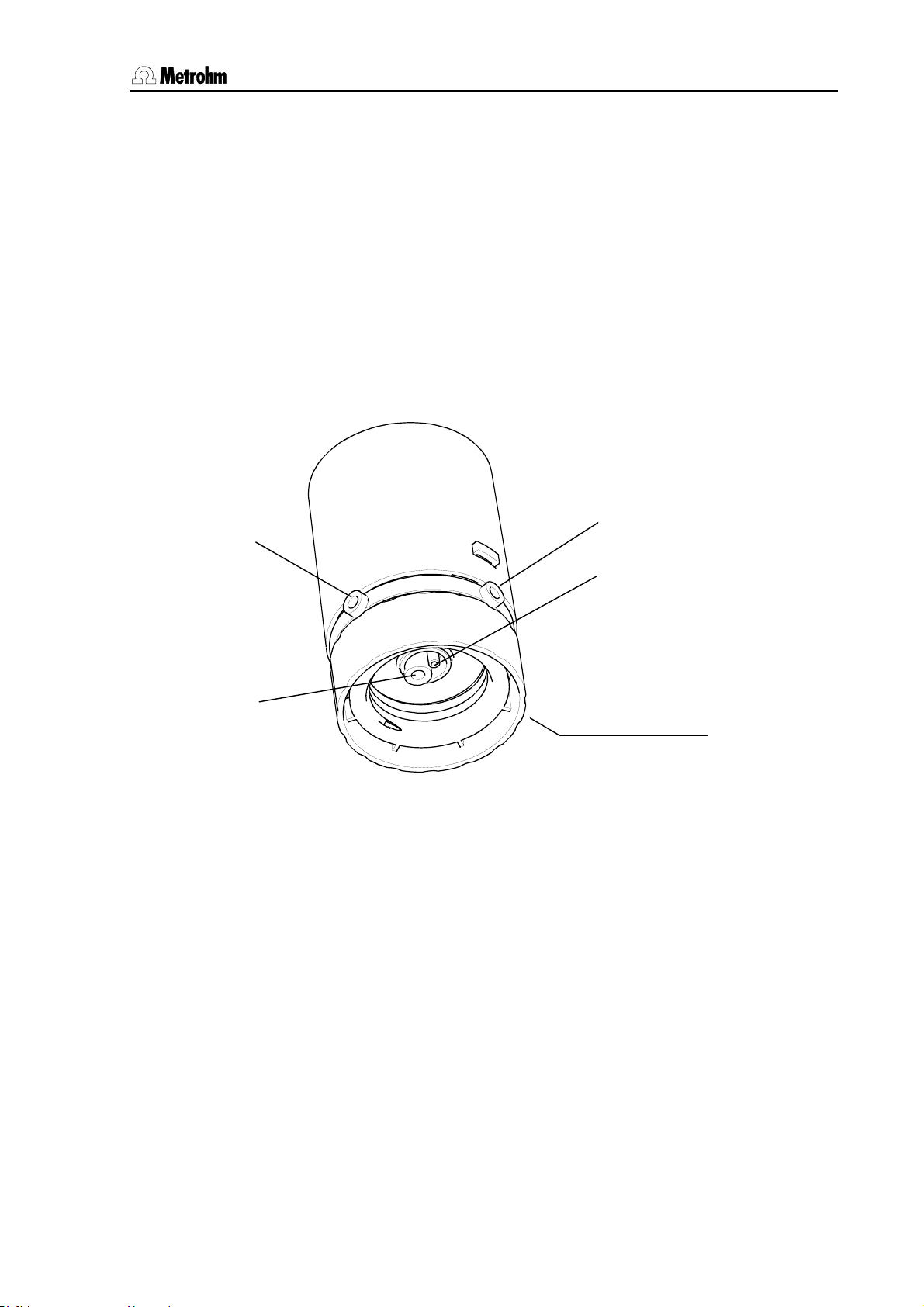
2.8 Dosing and liquid handling
2.8.2 Liquid handling functions
The Sample Processors can use the numerous capabilities of a
Metrohm Dosino (700 or 800) to the full extent. The four ports of the
Metrohm Dosing units for the Dosino can be used as outlet or inlet
ports as defined by the user. This means that not only simple addition
and filling tasks can be carried out, but complex liquid handling tasks
such as pipetting or sample transfer can be carried out without any
problems.
The dosing functions of the Metrohm Sample Processors are to be
used in such a way that, in addition to the function, the port at which the
function is to be carried out is also given. This means the Dosing unit
inlet or outlet to which the stopcock first moves in order that the required function is carried out.
Port 1
VENT/0 (venting)
Port 2
Port 4
Port 3
Fig. 8 Dosing unit - ports
Metrohm 838 Advanced Sample Processor, Operation 59
Page 68

2.8 Dosing and liquid handling
2.8.3 The DOS command
The liquid handling command DOS has two parameters:
General:
Example:
Parameter: drive.port Volume or function
Example:
means: On all the connected dosing devices the cylinder is filled via the default
Default ports: The default ports are the ports assigned in the parameter menu under
2.8.4 Pictograms
DOS: Address Function
DOS: 1.1 5 mL
(negative volume permitted)
for drive: * = all dosing drives
for port: * = default port for particular function
DOS: *.* fill mL
port.
>Dosing unit def., see also Section 2.2.4.
For complex liquid handling tasks only Dosinos (700 or 800 models)
can be used as dosing drive. In order to clarify the various functions
and processes the following pictograms are used on the next few
pages.
The following arrangement applies:
Function
Port
11
Default:
Dosing port 1
The pictograms above show the default settings..
The arrow represents the direction of motion of
the piston in the dosing cylinder.
The stopcock position is shown beneath the cylinder wherever necessary.
22
Default:
Filling port
33
Default:
Dosing port 2
44
Default:
Drain port
60 Metrohm 838 Advanced Sample Processor, Operation
Page 69

2.8 Dosing and liquid handling
2.8.5 Liquid handling functions in detail
Dosing
Example:
DOS: 1.1 : 1.000 mL Default port = 1
'Normal' dosing can be carried out by entering a volume. Automatic
cylinder filling is triggered neither before nor after the dosing process.
If the dosing piston reaches 'max. Volume' mark (10'000 impulses) during the dosing process then the cylinder will be refilled.
11
Dosing a negative volume
Example:
DOS: 1.2 : -1.000 mL Default port = 1
If a negative value is set for a volume then the dosing process will take
part in the opposite direction, i.e. a liquid will be aspirated through the
given port. Automatic cylinder filling is triggered neither before nor after
22
the dosing process.
If the dosing piston reaches the zero mark during the dosing process
then the cylinder will be refilled.
Do not select any volume that is larger than the nominal cylinder volume. Aspiration should take place with a single piston stroke.
This function can be used for pipetting.
Filling
33
Example:
DOS: 1.3 : fill mL Default port = 2
Filling the cylinder can be carried out from a freely selectable port. After
the filling process the stopcock remains at the selected port.
Metrohm 838 Advanced Sample Processor, Operation 61
Page 70

2.8 Dosing and liquid handling
Exchanging Dosing unit
Example:
DOS: 1.2 : release mL Default port = 2
This command can be used before exchanging a Dosing unit to fill the
cylinder via the given port. In this way, for example, air can be aspirated via Port 4.
After the cylinder has been filled the stopcock will move to Port 2. The
dosing drive can then be removed from the Dosing unit.
22
Preparing the Dosing unit
Example:
DOS: 1.* : prepar. mL Default port = 1
In order to prepare a Dosing unit for use a complex procedure is
started: first the cylinder contents are ejected via the given port, then
the volume of the filling tubing is drawn in and ejected again via the
given port. All the connected pieces of tubing are then filled bubblefree (tubing length > 0 mm) and finally the cylinder is filled again.
The volumes of the connected pieces of tubing (calculated from length
and diameter) are taken into account during the whole procedure.
Automatic emptying
Example:
DOS: 1.4 : empty mL Default port = 1
Automatically emptying the Dosing unit takes place according to a
complex procedure: first the cylinder contents are ejected via the given
port, the ejection tubing is then briefly rinsed with reagent from the filling tubing and then all the pieces of tubing are emptied in sequence.
Air is always aspirated via the drain port (default: Port 4) for emptying.
The volumes of the connected pieces of tubing (calculated from length
and diameter) are taken into account during the whole procedure.
44
62 Metrohm 838 Advanced Sample Processor, Operation
Page 71

2.8 Dosing and liquid handling
Ejecting
Example:
DOS: 1.1 : eject mL Default port = 1
The whole cylinder contents are ejected via the given port. The piston
is lowered beyond the max. volume mark to the stop.
This command should be used for removing air bubbles.
11
Run piston to end volume
Example:
DOS: 1.1 : endVol mL Default port = 1
The cylinder content is ejected via the given port. The piston is run to
the max. volume mark.
This command should be used for the pipetting functions.
11
Compensating the mechanical play
44
33
Example:
DOS: 1.4 : compen. mL Default port = 1
As the Dosing units are exchangeable, the coupling of the Dosino
connecting rod (spindle) has a slight degree of mechanical tolerance
which is noticeable when the direction of the piston movement
changes. This tolerance can be compensated. This is done by first
making a short piston movement in the same direction as the previous
piston movement, followed by an equivalent piston movement in the
opposite direction.
Stopcock rotation
Example:
DOS: 1.3 : port mL Default port = 1
The stopcock rotates to the given port. No piston movement takes
place. The direction of rotation is determined by the parameter
cock direction under >Dosing unit def. in the parameter menu.
stop-
Metrohm 838 Advanced Sample Processor, Operation 63
Page 72

3.1 Sample racks
3 Appendix
3.1 Sample racks
A sample rack is a turntable that accommodates sample vessels and is
placed on the Sample Processor. In order to be able to process different shapes and sizes of sample vessels various types of sample rack
can be used and easily exchanged. The number of samples that a rack
can accommodate depends on the diameter of the sample beakers.
• With the 838 Advanced Sample Processor all of the Metrohmsample racks with 42 cm diameter can be used. These are also usable with the Sample Processor models 778 and 814.
3.1.1 Metrohm standard sample racks
Article no. /
Rack type
6.2041.310 12 250 mL Metrohm titration beaker 65 mm 000001
6.2041.320 16 150 mL beaker 55 mm 000010
6.2041.340 24 75 mL Metrohm titration beaker 35 mm 001000
6.2041.350 48 *) 75 mL Metrohm titration beaker 35 mm 010000
6.2041.360 12 150 mL beaker or
6.2041.370 14 200 mL disposable beaker 55 mm 000011
6.2041.380 14 8 oz disposable beaker 59 mm 000101
6.2041.400 * 126+2 *) 11 mL sample tube
6.2041.410 * 141+1 *) 11 mL sample tube
6.2041.430 * 127+2 *) 11 mL sample tube
6.2041.440 * 148+3 *) 11 mL sample tube
No. of
samples
Type of sample vessel Vessel
diameter
55 mm 100000
200 mL disposable beaker
16 mm
250 mL Metrohm titration beaker
500 mL beaker
2x 300 mL beaker
3x 300 mL beaker
65 mm
16 mm
71 mm
16 mm
68 mm
16 mm
68 mm
Magnet code
(predefined)
001010
001010
010001
010100
6.2041.450** 56 + 56 50 mL PP sample beakers
11 mL sample tube
6.2041.750 * 36 11 mL sample tube 16 mm 011000
* recommended for IC applications
**
recommended for VA applications
On request we can supply further user-defined racks that can be defined in the instrument via PC software. The beaker positions can be arranged as required.
64 Metrohm 838 Advanced Sample Processor, Appendix
30 mm
16 mm
100100
Page 73

3.1 Sample racks
3.1.2 Magnet codes
Each individual sample rack can be identified unambiguously by a
magnet code. Magnet pins attached to the base of the rack can be arranged to form a 6-place binary code. The Sample Processor can then
automatically recognize which rack has been placed on it if the rack is
located at the starting position after initialization.
When a rack is changed it should first be brought to the starting position by pressing the <RACK> key. In this way the rack can be posi-
tively recognized, which makes correct beaker positioning possible.
Each type of rack is assigned to an internal position table, in which the
angle of rotation and distance to the center of the rack is defined for
each rack position.
When a sample series is started the Sample Processor automatically
moves the rack to the starting position so that its magnet code can be
read off. This ensures that the beaker positions coincide with the internal position table of the current rack.
The standard racks supplied by Metrohm are already provided with a
predefined magnet code for each type of rack. If several racks of the
same type are in use then the magnet pins can be arranged differently
to allow the unambiguous identification of each individual rack.
3.1.3 Rack data
Magnet code format (examples):
000001 i.e. only one magnet inserted, Bit 0
000101 i.e. two magnets inserted, Bit 0 and 2
63 different combinations are possible. Code 000000 stands for "no defined code".
In many applications the method and beaker sizes must be observed
exactly. As sample racks are intended for particular beaker sizes, the
rack definitions also contain, in addition to the rack positions themselves, data about the lift positions that are directly associated with the
particular beaker size.
The following data can be defined for each rack:
Rack name Unambiguous identification, ordering
number is standard
Code Magnet code for automatic rack rec-
ognition
Work position Working height for Lift 1 and 2
Rinse position Rinsing height for Lift 1 and 2
Shift position Shifting height for Lift 1 and 2
Special position Additional height for Lift 1 and 2
*
*
*
*
Beaker radius Radius of sample beaker
Beaker sensor Beaker checking mode
Metrohm 838 Advanced Sample Processor, Appendix 65
Page 74

3.1 Sample racks
Special beaker positions 16 reserved rack positions with individ-
ual working heights, beaker radius and
beaker sensor test
The rack name is used for the unambiguous identification of a rack.
The standard name stored for the rack is the ordering number. In a
method, this can be assigned to a particular rack name (see Section 2.3.1). The automatic rack recognition ensures that if an incorrect
rack is used this will be recognized and the user will be informed of this.
The code is used for automatic rack recognition. You must make sure
that this 6-place binary code coincides with the actual magnet code set
on the rack. Rack codes can be altered as required. However, they
must always be assigned to a single rack only. Avoid the use of the
predefined codes for the standard racks supplied by Metrohm, see also
p. 64.
The working position is used for defining the lift position at which a
sample is to be processed. This means that the ideal setting for a particular sample rack can be defined depending on the height of the
sample beakers. In manual operation this working position can be
moved to directly with the <END> key. In a run sequence this can be
programmed with
LIFT :1 : work mm.
The rinsing position is used for defining the lift position at which, for
example, the electrode is to be rinsed. This means that the ideal setting
for a particular sample rack can be defined depending on the height of
the sample beakers. In a run sequence this can be programmed with
LIFT: 1: rinse mm.
The shifting position is used for defining the lift position at which the
rack can be rotated. If the lift is located below the shift position then it
will be moved automatically to the shifting height before the rack is rotated. This safety feature prevents the electrode from being damaged
by rotational movements of the rack to a large extent. However, a prerequirement is that this shifting height is set correctly. In a run sequence
the movement of the lift to the shift position can be programmed with
LIFT: 1 : shift mm.
The special position is a further user-defined lift position. For example,
when pipetting with a robotic arm it can be selected so that the pipet tip
is located directly above the sample solution so that a separating bubble (air gap) is formed. In a run sequence this can be programmed with
LIFT: 1 : special mm.
The beaker radius can be used to prevent a titration head from trying
to enter a beaker which is too narrow for it, which could damage the
electrode or sample beaker. By entering the beaker radius a Sample
Processor can decide whether a titration or transfer head on the lift will
“fit” into the particular sample beaker, see also Section 2.2.
A beaker sensor is not available for the 838 Advanced Sample Processor at this time.
66 Metrohm 838 Advanced Sample Processor, Appendix
Page 75

3.1 Sample racks
Special beakers
Special beakers are reserved positions on a sample rack. Up to 16
special beaker positions can be defined per rack. They can be selectively moved to during a run sequence without interrupting the sample
series run or interfering with it. Special beakers can be used for rinsing
the electrode during a sample sequence or for calibrating an electrode
in a start sequence (buffer solutions), etc.
Reserved special beaker positions are automatically recognized in a run
sequence and are skipped over when the individual sample beakers
themselves are being processed.
Special beakers are moved to with
MOVE 1 : spec.1.
The following settings can be made separately for each special beaker
position on a rack:
• Rack position
• Working height at Tower 1
• Working height at Tower 2
• Beaker radius
• Beaker sensor
If a special beaker is required in a run sequence, but the Sample Processor cannot find a beaker at the reserved position, then an error message will always appear.
Metrohm 838 Advanced Sample Processor, Appendix 67
Page 76

3.2 The Remote interface
3.2 The Remote interface
Connected peripheral devices can be controlled via the Remote interface (25-pin socket).
Fourteen lines are available for the output of signals (Output 0–13).
Eight lines (Input 0–7) are available for receiving signals (e.g. the
"Ready" signal of a Metrohm device).
Metrohm instruments should only be connected with the Metrohm Remote cables provided.
3.2.1 Output lines
The 14 output lines of the Remote socket can be set as required in both
manual operation as well as in a run sequence with the Control command (CTL). This is done by setting a 14-place binary pattern in which
each bit is assigned to an output line.
Output 13 12 11 10 9 8 7 6 5 4 3 2 1 0
Bit 13 12 11 10 9 8 7 6 5 4 3 2 1 0
(bits are always numbered from right to left)
sets output line 1 to active (= set), for example, with a con-
3.2.2 Input lines
is waiting for an active input on line 0 (1=set).
Example:
CTL Rm ************1*
nected Titrino this would be a Stop command. 0 resets the
output line to inactive.
We recommend that non-relevant output lines are masked with an asterisk (∗) in order that the condition of these lines are not altered.
The 8 input lines of the Remote socket can be scanned during a
method sequence with the SCAN command (SCN). The method sequence will be halted until the given binary pattern coincides with the effective condition of the input lines (e.g. the status of the 'Ready' line for
scanning the determination end of a Metrohm device). This is done by
setting an 8-place binary pattern, in which each bit is assigned to an input line. When the patterns coincide the run sequence will continue with
the next command line. In manual operation the SCAN command is
used for displaying the status of all input lines.
Input 7 6 5 4 3 2 1 0
Bit 7 6 5 4 3 2 1 0
Example:
(bits are always numbered from right to left)
SCN Rm *******1
Input lines that are not of interest or for which no defined condition can
be predicted should also be masked with an asterisk (∗).
external START (see configuration 2.2.1) is switched on then Re-
If
mote lines Input 7 and Input 6 will be reserved for external START and
STOP.
68 Metrohm 838 Advanced Sample Processor, Appendix
Page 77

3.2 The Remote interface
In order to simplify the use of Remote commands, particularly when
several devices are linked together with Metrohm cables, predefined binary patterns are available as command parameters for the commands
CTL and SCN for standard conditions. These are:
3.2.3 SCN command
Parameter Signal pattern Function
Ready1 *******1 waits for "ready" condition of 732/1
End1 ****1*** waits for the EOD impulse from 732/1
End2 *1****** waits for the EOD impulse from 732/2
Wait1 *****1** waits for active Remote line 2 set by 732/1 or 797
Wait2 ***1**** waits for active Remote line 4 set by 732/2
Wait* ***1*1** waits for active Remote line 2 and 4 set by 732/1 and 732/2
Pump1 ? ******1* waits for active IC pump 709/1
Pump2 ? **1***** waits for active IC pump 709/2
Pump* ? **1***1* waits for active IC pumps 709/1 and 709/2 laufen
3.2.4 CTL-Befehl
Parameter Signal pattern Function Signal
INIT 00000000000000 initializes the Remote interface static
INIT 732/819 ***0000*000**0 initializes the Remote lines of 732 or 819 static
PROG R/S 1 ***000*******1 starts/stops the time program of 819/1 pulse (200 ms)
PROG R/S 2 ******0*100*** starts/Stopps the time program of 819/2 pulse (200 ms)
PUMP R/S 1 ***001*******0 starts/stops IC pump 818/1 pulse (200 ms)
FILL A 1 ***010*******0 switches valve A of 820/1 to "Fill" pulse (200 ms)
INJECT A 1 ***100*******0 switches valve A of 820/1 to "Inject" pulse (200 ms)
FILL B/STEP 1 ***001*******1 switches valve B of 820/1 to "Fill" pulse (200 ms)
INJECT B 1 ***110*******0 switches valve B of 820/1 to "Inject" pulse (200 ms)
ZERO 1 ***011*******0 activates autozero of 819/1 pulse (200 ms)
PUMP 833 ein ************1* starts the pump of a 833 static
PUMP 833 aus ************0* Stopps the pump of a 833 static
STEP MSM 833 ***********1** advances a step of the suppressor module 833 pulse (200 ms)
*************1 starts or advancesdevice 1 (e. g. 797 VA Com-
static
putrace)
Metrohm 838 Advanced Sample Processor, Appendix 69
Page 78

3.3 LEARN mode
3.3 LEARN mode
The LEARN mode is used for three types of application:
• Interactive setting of lift and robotic arm positions
• Rack adjustment
• Interactive parametrizing sequence commands
3.3.1 Setting lift and robotic arm positions
The fine adjustment of defined positions, such as the working height of
a lift, can be made by entering the height in mm. But it is recommended
to use the LEARN function to run a lift or a robotic arm to a certain position by using the arrow keys of the keypad.
Example: procedure for setting the 'Work height at Tower 1’
• Use manual operation to move to a rack position (at Tower 1).
• Open configuration menu (with the <CONFIG> key).
LEARN mode
The quicker an arrow key
is repeatedly pressed, the
higher the speed of the lift
or the longer the particular movement path.
Example: procedure for setting 'External position 1 at Tower 1’
LEARN mode
The quicker an arrow key
is repeatedly pressed, the
higher the swing rate or
the larger the particular
swing angle.
• Open submenu
>rack definitions and load the data of the rack
which is currently on the turntable.
• Select
work position T1.
• Press <LEARN> key.
• Use the <> and <> keys to move the lift to the re-
quired position.
• Accept the lift position with the <ENTER> key.
• If necessary modify the position (in mm) by entering num-
bers.
• Use manual operation to move to a sample beaker (at Tower 1)
and move the lift to a suitable lift position.
• Open configuration menu (with the <CONFIG>) key.
• Select submenus
>tower 1 / swing head 1 and external pos.1.
• Press <LEARN> key.
• Use the <> and <> keys to move the robotic arm
until it is in the required position.
• Accept the robotic arm position with <ENTER>.
• If necessary modify the position (in °) by entering numbers.
70 Metrohm 838 Advanced Sample Processor, Appendix
Page 79

3.3 LEARN mode
3.3.2 Rack adjustment
If necessary, each sample rack can be finely adjusted, i.e. the rack offset is determined in the direction of rotation. A requirement for this is
that the working height has already been set for the particular rack and
that the rack settings have been stored.
Procedure:
• Position sample rack on turntable and initialize with <RACK>.
• Open configuration menu (with <CONFIG>) and select sub-
menu
>rack definitions.
• Under
• Select
>>recall rack call up the definitions for the current rack.
rack offset.
• Press <LEARN> and confirm the question
<ENTER>.
• The rack rotates to rack position 1.
• Confirm the question
adjust tower 1 ? with <ENTER>.
• The lift moves to the working position.
• Use the arrow keys to exactly align rack position 1 with the beaker
sensor at Tower 1.
• Confirm the adjustment with <ENTER>.
• The rack offset (in °) is accepted in accordance with the adjust-
ment carried out.
3.3.3 Parametrizing sequence commands
As when editing a method the parameters of a command can most
easily be altered interactively, i. e. by altering them manually, particular
commands are "adaptive". When editing a sequence the LEARN func-
tion allows certain commands to be carried out via manual operation.
The resulting parameter (e.g. the lift position or the status of the input
lines of the Remote interface) can then be adopted in the current command line. The LEARN function can be used repeatedly. Once times or
volumes have been "learned" the values will always be added up. This
is extremely useful for the determination of the pumping time, where the
optimal duration of the rinsing process can be determined interactively
in this way.
adjust RACK ? with
Procedure for editing methods:
• Enter command or select existing command line
• Press <LEARN> key
• The function starts, the "LEARN" LED lights up
• Press <LEARN> key
• The function is stopped, the "LEARN" LED blinks
Metrohm 838 Advanced Sample Processor, Appendix 71
Page 80

3.4 Disabling keypad functions
• Accept the value with the <ENTER> key (or start the LEARN function
again)
• The LEARN LED goes out; the next command line appears
The LEARN function is available for the following commands:
Command Adaptive parameter Type of function
LIFT Lift position in mm absolute
PUMP Pumping time in s additive
STIR Stirring time in s additive
WAIT Waiting time in s additive
DOS Dosing volume in mL additive
SCN Rm Status of 8 Remote lines "live" value
SCN RS Received character string "live" value
3.4 Disabling keypad functions
Certain user dialog areas can be made inaccessible to untrained users.
Various dialog areas or keys can be disabled. For example, this can be
used to prevent a method from being overwritten accidentally or parameters from being altered.
The
>keyboard options menu for the corresponding settings is opened
by keeping the <CONFIG> key pressed down when the Sample Processor is switched on. This menu can still be accessed even if the whole
keypad has been disabled.
The individual key functions that can be disabled are:
3.4.1 Disable whole keypad
In routine work, if only a single particular method is used, it may be advisable to prevent manual manipulations on the Sample Processor. For
this reason it is possible to disable (almost) all the keypad keys. The
<START>, <STOP> and <CLEAR/RESET> keys always remain
accessible, so that it is always possible to start and stop methods.
lock keyboard: ON disables all the keypad keys (with the above ex-
ceptions).
3.4.2 Disable configuration
The configuration of the Sample Processor can be protected against
being overwritten. All the settings in the configuration menu and it's submenus can then no longer be accessed.
lock <CONFIG>: ON disables the <CONFIG> key.
3.4.3 Disable parameter
If user-defined methods are normally used then it may be advisable to
prevent the stored method parameters from being overwritten. The parameter menu and it's sub-menus can be made inaccessible.
lock <PARAM>: ON disables the <PARAM> key.
72 Metrohm 838 Advanced Sample Processor, Appendix
Page 81

3.4 Disabling keypad functions
3.4.4 Disable method storage functions
It is extremely advisable to prevent stored methods from being accidentally deleted. It should only be possible to delete methods by deliberately switching off the disabling function.
>>user methods + <ENTER> opens the submenu for disabling the
method storage functions.
lock method recall: ON prevents the loading of methods.
lock method store: ON prevents methods from being stored.
lock method delete: ON prevents methods from being deleted.
3.4.5 Disable display
If the Sample Processor is only to be operated by using external control
software, the display for manual operation can be switched off.
lock display: ON switches off the display.
Metrohm 838 Advanced Sample Processor, Appendix 73
Page 82

3.5 786 Swing Head settings
3.5 786 Swing Head settings
If a 786 Swing Head with robotic arm is to be mounted then its configuration data must be entered in the setup menu of the Sample Processor
before. The most important data:
• Swing radius (=length of robotic arm)
• Swing arm offset
• Max. swing angle
• Swing direction
Setup menu of the Sample Processor
Procedure:
• Switch off instrument
• Keep <CONFIG> key pressed down and switch on the in-
strument again
• In the menu
>>swing head 1.
• Make the following settings:
setup >changer setup select the submenu
Axis distance
The axis distance is the horizontal distance between the axis of
rotation of the rack and the swing axis of the robotic arm.
Default settings:
axial distance 166.00 mm
Swing offset
The swing offset is the physical angle offset of the specific robotic arm model, see the Instructions for Use for the 786
Swing Head.
Default values:
swing offset 8.00°
Max. swing angle
The maximum swing angle is the useable swinging range
(relative angle). The starting and finishing positions of this
range (as absolute angle positions) are determined by the
swing offset (see above) and the Swing Head drive. Because
of its construction, each robotic arm model has a different
value for the max. swing range, see the Instructions for Use for
the 786 Swing Head. This value can also be reduced if necessary.
Default values:
Max. swing angle 117.00°
74 Metrohm 838 Advanced Sample Processor, Appendix
Page 83

3.5 786 Swing Head settings
Swing radius
The swing radius depends on the length of the robotic arm
and, together with the axial distance (see above), is the most
important parameter for accurately moving to a rack position.
The distance from the robotic arm axis to the middle of the
processing head at the front of the robotic arm is decisive. The
various robotic arm models have different swing radii, see the
Instructions for Use for the 786 Swing Head.
Default values:
swing radius 112 mm
Rotation offset
The rotation offset does not normally need to be altered. It is
only used if a Swing Head is to be mounted on the tower with
a lateral displacement.
Default value:
rot. offset 0.00 mm (do not alter)
Swing direction
In principle the swing direction of the robotic arm can be selected as required. If two Swing Heads are mounted on a 2tower model then you must take care that the two robotic arms
do not come into conflict. For this reason the robotic arm at
Tower 1 should always be mounted so that it swings to the
right and that at Tower 2 to the left.
Right-swinging mounting means: swing direction –
Left-swinging mounting means: swing direction +
Default values:
Swing direction: + (at Tower 2, swing to the left)
Adjustment rate
When the RACK command is carried out after switch-on (rack
initialization) the robotic arm is automatically adjusted to the
zero position. If the highest possible degree of positioning accuracy of the robotic arm is required the rate of the adjustment
process can be reduced. However, this also lengthens the duration of the automatic adjustment process, but increases the
precision.
Default value:
Adjust rate.: normal
After the settings for the robotic arm have been entered the <QUIT>
key must be pressed three times. The settings become active the next
time that the instrument is switched on.
Metrohm 838 Advanced Sample Processor, Appendix 75
Page 84

3.6 Error messages
3.6 Error messages
If a fault should occur then the execution of the active command will be
QUIT
List of possible error messages and their causes:
∗ battery low The battery for the permanent storage of the user data must
∗ beaker too small The rack position which has been moved to has a smaller
stopped and an error message shown (display blinks). This must be
confirmed with the <QUIT> key.
If the Sample Processor is processing a series of samples when the
fault occurs then it will switch to the HOLD status. When the cause of
the fault has been found and remedied the sample series can be restarted with the next command by pressing the <START> key. If it is
not possible to remedy the fault then the method can be stopped with
<STOP>.
be replaced.
beaker radius than that defined as the min. beaker radius for
the particular lift. There is a risk of damage. Check the sample rack, its configuration settings and those of the selected
tower.
∗ changer overload Load too high, or resistance to the action to be carried out.
After <QUIT> the Sample Processor will be initialized again.
∗ dos.## not exec A fault has occurred at the given dosing device.
∗ dos.## not ready The selected dosing device cannot carry out the particular
command as it is carrying out a different action or the current
instrument status does not allow it to be carried out.
∗ dos.unit ## missing The selected dosing device has not been connected.
∗ dos.unit ## overload The selected Dosing unit cannot carry out a dosing com-
mand. Check the buret and piston.
∗ invalid position The selected sample position does not exist or is defined as
a special beaker or the selected special beaker has not been
defined. The selected lift position may lie outside the max.
stroke path.
∗ invalid rack code The rack code read in by the Sample Processor cannot be
found in the internal table.
∗ rack data missing No sample rack in position, or no rack data can be found for
the sample rack currently on the turntable.
∗ RS232 error The transmission parameters of the RS232 interface do not
coincide with those of the receiving device.
76 Metrohm 838 Advanced Sample Processor, Appendix
Page 85

3.6 Error messages
∗ SCAN timeout The connected device has not transmitted the expected sig-
nal within the defined timeout time. The sample determination may not have been carried out properly, or the connection has been interrupted. Check the connected device.
* service recommended The warning limit of the running time meter has been
reached. It is time for the Sample Processor to be serviced.
Please contact your local Metrohm service department.
∗ user memory full The memory for the user-defined methods is full. Before new
methods can be stored methods that are not used, or only
used infrequently, must be deleted.
∗ wrong rack The rack placed on the turntable is not the rack assigned to
the method under
parameters.
trap error xxx Unexpected program error; switch instrument off and then on
again.
No display, LEDs Tower 1
and Tower 2 light up LCD error (system error 7). Contact Service.
Metrohm 838 Advanced Sample Processor, Appendix 77
Page 86
3.7 Initializing the working memory
3.7 Initializing the working memory
With this diagnostic step the default values for instrument parameters
can be entered via the keypad and the instrument returned to its original condition. This measure is important with respect to the following
points:
In rare cases it could happen that massive interference signals such
as current peaks, lightning, etc. could affect the contents of the data
memory. If the data memory contents are undefined then this could
lead to a system crash.
The Sample Processor has different ways of initializing the working
memory. Either the complete data memory (
ram, config, setup, assembly
) can be overwritten with the default
values.
Although the instrument number is retained, initialization should only
be carried out when absolutely necessary, as this deletes the stored
user data (etc.).
• Keep key <9> pressed down when the instrument is switched on.
all) or only parts of it (pa-
diagnosis
>RAM initialization
• Press the <ENTER> key to open the following diagnosis menu:
>RAM initialization
select: param
>RAM initialization
select: config
>RAM initialization
select: setup
>RAM initialization
select: assembly
>RAM initialization
select: all
Set method parameters with default values.
The table shows which parts of the working memory are affected by the
corresponding initialization versions. If a system crash occurs (undefined display, no reaction to pressing keys, etc.) we recommend the initialization version "
Set instrument configuration with default values.
Set setup parameters with default values.
Set assembly parameters with default values.
Delete all user-defined methods
all".
78 Metrohm 838 Advanced Sample Processor, Appendix
Page 87

3.7 Initializing the working memory
• If necessary, press the <SELECT> key several times until this ap-
pears:
>RAM initialization
select: all
• Press <ENTER>.
diagnosis
>RAM test
• Press <ENTER>.
• Press <QUIT>.
The instrument finishes the diagnosis process and carries out a start-up
reset.
Metrohm 838 Advanced Sample Processor, Appendix 79
Page 88

3.8 Standard methods
3.8 Standard methods
The following pages contain a list of the user methods supplied together with explanations of important commands. They are used, if the
838 Advanced Sample Processor is not being controlled directly by a
PC software.
These standard methods are therefore mostly used in combinations of
the 838 Advanced Sample Processor with the Metrohm VA instruments,
e. g. the VA Computrace 797. Synchronizing the instruments is
achieved by activating signals via Remote lines.
An overview of the standard methods for voltammetric analysis stored
in the 838 is given below.
Method name Function
LAT Linear Approximation Technique
Standard addition for brightener (electroplating bath analysis)
MLAT Modified Linear Approximation Technique
Standard addition for brightener (electroplating bath analysis)
DT Dilution Titration
Suppressor analysis ("Dilution Titration Technique”, electroplating
bath analysis)
VA Voltammetric Trace Analysis
We recommend that each new method is worked through step by step
with the TRACE function before it is started for the first time and
adapted to suit the particular requirements
80 Metrohm 838 Advanced Sample Processor, Appendix
Page 89

3.8 Standard methods
3.8.1 Method "LAT"
LAT = Linear Approximation Technique
Application
Brightener analysis (electroplating bath analysis)
System setup
See 8.838.1303 Installation Instructions, Section 3.6 or 8.797.1013
Hardware Manual of the 797 VA Computrace, Section 2.11.5.
Run sequences for the 838 Advanced Sample Processor
838 Advanced S.Proc. 00030 5.838.0010
parameters
method LAT
number of samples: rack
>start sequence
1 CTL:Rm: INIT
2 MOVE 1 : sample
3 CTL:Rm: *************1
4 CTL:Rm: *************0
>sample sequence
1 SCN:Rm : *****1**
2 MOVE 1 : sample
3 LIFT: 1 : work mm
4 PERISTALT: 300 s 10
5 CTL:Rm: *************1
6 CTL:Rm: *************0
7 MOVE 1 : +28
8 LIFT: 1 : work mm
9 PERISTALT: 5 s 10
10 SCN:Rm : *****1**
11 PERISTALT: 300 s 10
12 CTL:Rm: *************1
13 CTL:Rm: *************0
>final sequence
>changer settings
>dosing unit def.
>timeout settings
>manual stop
6.2041.450 sample rack
- report header with instrument ID and program version
- method name
- number of samples (e. g. entire rack)
- initialize all Remote lines
- approach first sample
- remote start of the 797 VA Computrace
- wait for advance signal of the 797 VA Computrace
- approach sample
- run lift and needle to work position
- transfer sample with peristaltic pump
- set Remote line: sample transfer ready
- approach rinsing vessel
- run needle to work position
- aspirate rinsing solution
- wait for advance signal of the 797 VA Computrace
- rinse needle and transfer tubing
- set Remote line: needle cleaning ready
----- miscellaneous settings -----
50 mL sample vessels can be placed on the two outer rings (11 mL
sample vessels on the two inner rings).
Arrangement: Place on the outer of the two rings alternately "Intercept
solution" and sample solution, on the inner of the two rings the rinsing
solution.
Example for an arrangement with 7 samples:
⇒ With 50 mL sample vessels: first sample on position 1, first rinsing
solution on position 29:
Metrohm 838 Advanced Sample Processor, Appendix 81
Page 90

3.8 Standard methods
1
2
3
30
31
58
59
86
87
28
29
57
85
112
27
56
55
84
83
111
Intercept solution
Sample
Rinsing solution
not used
Note: Although the first sample is placed on position 2, posi-tion 1
remains the starting position in the start sequence of the method at
the 838 (recording the "Intercept value").
Before each start, define the position of the first sample vessel. Press
the <SAMPLE> key of the 838 keypad and enter the rack position.
Find more information in the 8.797.8011 Software Manual of the 797 VA
Computrace, see section 8.6.
82 Metrohm 838 Advanced Sample Processor, Appendix
Page 91

3.8 Standard methods
3.8.2 Methode "MLAT"
MLAT = Modified Linear Approximation Technique
Application
Brightener analysis
System setup
See 8.838.1303 Installation Instructions, Section 3.6 or 8.797.1013
Hardware Manual of the 797 VA Computrace, Section 2.11.4.
Run sequences for the 838 Advanced Sample Processor
838 Advanced S.Proc. 00030 5.838.0010
parameters
method MLAT
number of samples: rack
>start sequence
1 CTL:Rm: INIT
2 MOVE 1 : sample
3 CTL:Rm: *************1
4 CTL:Rm: *************0
>sample sequence
1 SCN:Rm : *****1**
2 DOS: 1.* : 30 mL
3 DOS: 2.* : 1 mL
4 CTL:Rm: *************1
5 CTL:Rm: *************0
6 DOS: *.* : fill mL
7 SCN:Rm : *****1**
8 MOVE 1 : sample
9 LIFT: 1 : work mm
10 PERISTALT: 300 s 10
11 CTL:Rm: *************1
12 CTL:Rm: *************0
13 MOVE 1 : +28
14 LIFT: 1 : work mm
15 PERISTALT: 5 s 10
16 SCN:Rm : *****1**
17 PERISTALT: 300 s 10
18 CTL:Rm: *************1
19 CTL:Rm: *************0
>final sequence
>changer settings
>dosing unit def.
>timeout settings
>manual stop
Note: The command lines 1 to 6 are only necessary, if dosing drives
are connected to the Sample Processor for adding auxiliary solutions.
In the 797 VA Computrace software the parameter "Dose auxiliary solution via sample processor" in the configuration dialog "Settings /
General settings / Automation" must be activated.
- report header with instrument ID and program version
- method name
- number of samples (e. g. entire rack)
- initialize all Remote lines
- approach first sample
- remote start of the 797 VA Computrace
- wait for advance signal of the 797 VA Computrace
- add VMS
- add suppressor solution
- set Remote line: Intercept solution ready
- fill dosing units
- wait for advance signal of the 797 VA Computrace
- approach sample
- run lift and needle to work position
- transfer sample with peristaltic pump
- set Remote line: sample transfer ready
- approach rinsing vessel
- run needle to work position
- aspirate rinsing solution
- wait for advance signal of the 797 VA Computrace
- rinse needle and transfer tubing
- set Remote line: needle cleaning ready
----- miscellaneous settings -----
If adding of auxiliary solutions is operated by the 797 VA Computrace, line 1 to 6 have to be deleted.
Metrohm 838 Advanced Sample Processor, Appendix 83
Page 92
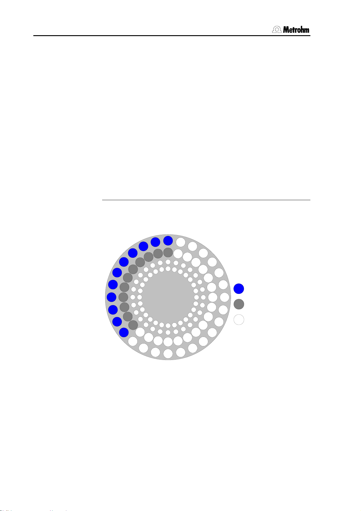
3.8 Standard methods
Using the method above, it is assumed that dosing drive 1 adds the
VMS solution and dosing drive 2 adds suppressor solution. The intercept solution is there mixed in situ by the 838 Advanced Sample Processor in the measuring cell.
The volumes added in method line 2 and 3 of the sample sequence are
to be adapted to the specific application. It is recommended to save
the modified methods separately under specific method names.
Only similar samples which require the same amount of auxiliary solutions can be processed in one sample series.
6.2041.450 sample rack
50 mL sample vessels can be placed on the two outer rings (11 mL
sample vessels on the two inner rings).
Arrangement: Place the samples solutions on the outer and the rinsing
solutions on the inner of the two rings.
Example for an arrangement with 11 samples:
⇒ With 50 mL sample vessels: first sample on position 1, first rinsing
solution on position 29:
1
2
3
30
31
58
59
86
87
28
27
29
56
112
55
84
83
111
57
85
Sample
Rinsing solution
not used
⇒ With 11 mL sample vessels: first sample on position 57, first rins-
ing solution on position 85.
84 Metrohm 838 Advanced Sample Processor, Appendix
Page 93

3.8 Standard methods
1
2
3
30
31
58
59
86
87
28
27
29
56
112
55
84
83
111
57
85
Sample
Rinsing solution
not used
Before each start, define the position of the first sample vessel. Press
the <SAMPLE> key of the 838 keypad and enter the rack position.
Find more information in the 8.797.8011 Software Manual of the 797 VA
Computrace, see section 8.6.
Metrohm 838 Advanced Sample Processor, Appendix 85
Page 94

3.8 Standard methods
3.8.3 Method "DT"
DT = Dilution Titration
Application
Suppressor determination
System setup
See 8.838.1303 Installation Instructions, Section 3.6 or 8.797.1013
Hardware Manual of the 797 VA Computrace, Section 2.11.3.
Run sequences for the 838 Advanced Sample Processor
838 Advanced S.Proc. 00030 5.838.0010
parameters
method DT
number of samples: 20
>start sequence
1 CTL:Rm: INIT
2 MOVE 1 : sample
3 CTL:Rm: *************1
4 CTL:Rm: *************0
>sample sequence
1 SCN:Rm : *****1**
2 MOVE 1 : sample
3 LIFT: 1 : work mm
4 CTL:Rm: *************1
5 CTL:Rm: *************0
6 SCN:Rm : *****1**
7 DOS: 1.* : 50 mL
8 CTL:Rm: *************1
9 CTL:Rm: *************0
10 DOS: 1.* : fill mL
>final sequence
1 SCN:Rm : *****1**
2 MOVE 1 : next
3 LIFT: 1 : work mm
4 CTL:Rm: *************1
5 CTL:Rm: *************0
>changer settings
>stirring rates
>dosing unit def.
>timeout settings
>manual stop
Note: The command lines 6 to 10 are only necessary, if a dosing
drive is connected to the Sample Processor for adding auxiliary solution. In the 797 VA Computrace software the parameter "Dose auxiliary solution via sample processor" in the configuration dialog
"Settings / General settings / Automation" must be activated.
- report header with instrument ID and program version
- method name
- number of samples (e. g. 20)
- initialize all Remote lines
- approach first sample
- remote start of the 797 VA Computrace
- wait for advance signal of the 797 VA Computrace
- approach sample
- run lift and needle to work position
- set Remote line: Sample ready
- wait for advance signal of the 797 VA Computrace
- add auxiliary solution (e. g. VMS) with Dosino
- set Remote line: auxiliary solution ready
- fill dosing unit
- wait for advance signal of the 797 VA Computrace
- approach next rack position
- run needle to work position
- set Remote line: cleaning solution ready
----- miscellaneous settings -----
If adding of auxiliary solution is operated by the 797 VA Computrace,
line 6 to 10 have to be deleted.
Using the method above, it is assumed that dosing drive 1 adds the
VMS solution. The volume added in method line 7 of the sample sequence has to be adapted to the specific application. It is recom-
86 Metrohm 838 Advanced Sample Processor, Appendix
Page 95

3.8 Standard methods
mended to save the modified methods separately under specific
method names.
Only similar samples which require the same amount of auxiliary solutions can be processed in one sample series.
Samples
The method parameter 'Number of samples' has to correspond exactly
to the real number of samples. Place a vessel with rinsing solution at
the end of the series on the rack.
6.2041.450 sample rack
Samples and auxiliary solutions are placed on the rack. It is recommended to use the two inner rings with 11 ml sample vessels. How frequently the calibration curve needs to be recorded (with
Calibration
technique "DT Record calibration curve") depends on the chemistry of
the bath.
Note: Place a vessel with water at the end of the series on the rack.
Arrangement: At the first position a Suppressor standard solution to record the calibration curve. Then samples, and, when a recalibration is
necessary, another Suppressor standard solution. At the end of the series place a vessel with water.
Example for a sample rack with 14 samples, 2 Suppressor standard solutions and one rinsing solution:
1
2
3
30
31
58
59
86
87
28
29
57
85
112
27
56
55
84
83
111
Suppressor standard
Sample
Rinsing solution
not used
Before each start, define the position of the first sample vessel. Press
the <SAMPLE> key of the 838 keypad and enter the rack position.
Find more information in the 8.797.8011 Software Manual of the 797 VA
Computrace, see section 8.6.
Metrohm 838 Advanced Sample Processor, Appendix 87
Page 96

3.8 Standard methods
3.8.4 Method "VA"
VA = Voltammetric trace analysis
Application
Voltammetric trace analysis
System setup
See 8.838.1303 Installation Instructions, Section 3.6 or 8.797.1013
Hardware Manual of the 797 VA Computrace, Section 2.11.
Run sequences for the 838 Advanced Sample Processor
838 Advanced S.Proc. 00030 5.838.0010
parameters
method VA
number of samples: rack
>start sequence
1 CTL:Rm: INIT
2 MOVE 1 : sample
3 CTL:Rm: *************1
4 CTL:Rm: *************0
>sample sequence
1 SCN:Rm : *****1**
2 MOVE 1 : sample
3 LIFT: 1 : work mm
4 PERISTALT: 300 s 10
5 CTL:Rm: *************1
6 CTL:Rm: *************0
7 MOVE 1 : +28
8 LIFT: 1 : work mm
9 PERISTALT: 5 s 10
10 SCN:Rm : *****1**
11 PERISTALT: 300 s 10
12 CTL:Rm: *************1
13 CTL:Rm: *************0
>final sequence
>changer settings
>stirring rates
>dosing unit def.
>timeout settings
>manual stop
6.2041.450 sample rack
- report header with instrument ID and program version
- method name
- number of samples (e. g. entire rack)
- initialize all Remote lines
- approach first sample
- remote start of the 797 VA Computrace
- wait for advance signal of the 797 VA Computrace
- approach sample
- run lift and needle to work position
- transfer sample with peristaltic pump
- set Remote line: sample transfer ready
- approach rinsing vessel
- run needle to work position
- aspirate rinsing solution
- wait for advance signal of the 797 VA Computrace
- rinse needle and transfer tubing
- set Remote line: needle cleaning ready
----- miscellaneous settings -----
50 mL sample vessels can be placed on the two outer rings (11 mL
sample vessels on the two inner rings).
Arrangement: Place the samples solutions on the outer and the rinsing
solutions on the inner of the two rings.
Example for an arrangement with 11 samples:
⇒ With 50 mL sample vessels: first sample on position 1, first rinsing
solution on position 29:
88 Metrohm 838 Advanced Sample Processor, Appendix
Page 97

3.8 Standard methods
1
2
3
30
31
58
59
86
87
28
27
29
56
112
55
84
83
111
57
85
Sample
Rinsing solution
not used
⇒ With 11 mL sample vessels: first sample on position 57, first rins-
ing solution on position 85.
1
2
3
30
31
58
59
86
87
28
27
29
56
112
55
84
83
111
57
85
Sample
Rinsing solution
not used
Before each start, define the position of the first sample vessel. Press
the <SAMPLE> key of the 838 keypad and enter the rack position.
Find more information in the 8.797.8011 Software Manual of the 797 VA
Computrace, see section 8.5.
Metrohm 838 Advanced Sample Processor, Appendix 89
Page 98

3.8 Standard methods
4 Index
< ......................................... 14
< NEXT>..................... 5, 49
< PREV>..................... 5, 49
<>, <> .............. 5, 13, 49
<*>...................................... 40
<CLEAR>................. 6, 11, 48
<CONFIG>............... 5, 72, 74
<CTRL>................................ 8
<DELETE> ............... 6, 26, 32
<DOS> ................................. 7
<END>...................... 5, 11, 49
<ENTER> ................. 6, 11, 13
<EXT>............................. 9, 53
<HOLD> ....................... 10, 48
<HOME> .................. 5, 11, 49
<INSERT>................ 6, 26, 32
<LEARN> ......... 18, 32, 70, 71
<LIFT>............................ 7, 50
<MOVE>............................... 6
<PARAM> ...................... 5, 73
<PUMP>............................... 7
<QUIT>............... 6, 11, 13, 48
<RACK> ................... 9, 53, 65
<SAMPLE> .................... 6, 34
<SCAN> ............................... 8
<SELECT> ........... 5, 6, 11, 46
<START> ................. 9, 33, 48
<STIR> ........................... 7, 51
<STOP> ................. 10, 31, 48
<USER METHOD>.............. 5
<VALVE>........................ 9, 53
<WAIT> ................................ 8
> ......................................... 14
786 Swing Head ....... 18, 35, 74
A _______________________
Absolute positioning............. 36
Absorber tube....................... 55
Acknowledgement................ 30
Active ........................ 41, 43, 68
Adjustment............................ 71
Adjustment rate .................... 75
Air bubbles............................ 56
Air inlet .................................. 30
Air inlet opening.................... 55
Angle..................................... 74
Angle of rotation ................... 35
Angle of rotation offset ......... 75
Angle positions ..................... 35
Approach position ................ 35
Arrow keys ........................ 5, 13
ASCII character..................... 42
Aspirate................................. 40
Aspirating air......................... 57
Aspiration.............................. 61
Attention.................................. 2
AutoInfo ................................ 44
Automatic emptying.............. 62
Automatic rack recognition... 66
Axis distance......................... 74
Axis of rotation ...................... 74
B ________________________
Basic settings ................. 16, 18
Battery................................... 76
Baud ..................................... 24
Beaker................................... 64
Beaker radius............ 18, 20, 66
Bechersensor ....................... 66
Beep ..................................... 16
Binary code........................... 65
Binary pattern ................. 41, 68
Brightener ................. 80, 81, 83
C ________________________
Changer settings .................. 27
Changing dosing unit ..... 57, 62
Character selection............... 14
Character set ........................ 24
Cock direction....................... 30
Code ..................................... 20
Colon .................................... 13
Command............................. 26
Command keys ...................... 6
Command line ...................... 26
Command sequence............ 25
Commands........................... 34
Communication commands. 41
Compensate ......................... 58
Compensation ...................... 63
Configuration .................... 5, 16
Configuration menu........ 16, 72
Connecting rod..................... 63
Continue method.................. 48
Contrast of display................ 16
Control command................. 68
Coupling ............................... 63
Creating methods................. 26
CTL ................................. 51, 68
CTL:Rm command ............... 43
Current sample position ......... 6
D ________________________
Danger.................................... 2
Data bits ............................... 24
Data input ......................... 6, 13
Data reception ...................... 24
Data transmission via serial
interface ........................... 44
Default port ..................... 39, 61
Default value........................... 6
Delete.......................... 6, 14, 22
Delete character ................... 14
Delete line ............................. 26
Delete rack definitions .......... 22
Deleting methods ................. 46
Diagnosis.............................. 78
Dialog arrangement.............. 12
Dialog language ................... 16
Diameter ............................... 23
Dilution Titration.............. 80, 86
Direction of rotation .. 27, 30, 36
Disable configuration............ 72
Disable display ..................... 73
Disable keypad..................... 72
Disable method storage ....... 73
Disable parameter ................ 72
Display................................ 3, 4
Disposable beaker ............... 64
DOS command......... 39, 51, 60
Dosimat ........ 23, 29, 39, 51, 54
Dosing ...................... 54, 56, 61
Dosing cylinder..................... 60
Dosing cylinder ejection ....... 58
Dosing device......................... 7
Dosing device connection......
................................... 23, 29
Dosing device control........... 39
Dosing device settings ......... 29
Dosing devices..................... 39
Dosing drive.......................... 23
Dosing functions................... 40
Dosing instruments .............. 54
Dosing outlet ........................ 55
Dosing port............... 29, 39, 51
Dosing rate ........................... 29
Dosing unit ........................... 55
Dosing units.......................... 23
Dosino ................ 29, 39, 54, 59
Dosino commands ............... 40
Drawing up a method........... 25
DT ......................................... 86
90 Metrohm 838 Advanced Sample Processor, Index
Page 99

4 Index
Duration ................................39
E ________________________
Eject ................................ 40, 63
Ejecting ................................. 63
Electroplating bath analysis....
................................... 80, 81
Elimination of mechanical play
......................................... 58
Empty.............................. 57, 62
Emptying the dosing unit...... 30
End volume..................... 58, 63
EndVol............................. 40, 63
Entry........................................ 6
EOD ......................................69
Error message ................10, 30
Exchange units .....................23
Ext.1 ...................................... 35
External position .......19, 35, 70
External start ............. 16, 48, 68
F ________________________
Fault ...................................... 76
Fill ......................................... 56
'FILL' ........................................ 4
Fill air bubble-free ................. 62
Fill automatically ...................40
Fill tubing ........................ 56, 62
Filling..................................... 61
Filling inlet ............................. 55
Filling port ............................. 29
Filling rate ............................. 29
Final sequence ..................... 26
First sample ............................ 6
Function selection................. 39
Functions .............................. 40
G ________________________
Gentle stop ...........................48
H ________________________
Handshake............................ 24
HOLD condition .................... 10
Hold method sequence ........ 10
HOLD status ................... 48, 76
I ________________________
IBM........................................ 24
Impulses ............................... 43
Inactive............................ 41, 43
Initial value ............................11
Initialize ...................................6
Initialize rack ............... 9, 45, 53
Initializing the working memory
......................................... 78
INJECT.................................... 4
Input.......................... 26, 41, 68
Input line ...................13, 16, 68
Insert ....................................... 6
Instrument dialog.................. 11
Interface control .................... 51
Interface signals.................... 51
Interrupt method ................... 48
Interrupt sample series ......... 48
Interruption............................ 10
K ________________________
Keypad.................................... 4
Overview............................. 4
Keys .................................... 4, 5
L ________________________
LAT........................................ 81
LEARN function........... 18, 26,
............................. 37, 41, 71
LEARN mode ............ 32, 38, 70
LEDs .......................................4
Length................................... 23
Length of robotic arm ...........75
Lift .....................................7, 37
Lift positioning.................. 50
Manual control ................. 49
LIFT ....................................... 50
Lift operation ........................... 5
Lift position ........................... 70
Lift positioning....................... 37
Lift rate .................................. 27
Line condition ........... 41, 43, 68
Linear Approximation Technique
................................... 80, 81
Lines ..................................... 25
Liquid Handling............... 40, 54
Liquid Handling functions..... 59
Lower ................................7, 37
M ________________________
Magnet code....... 20, 64, 65, 66
Maintenance .........................17
Manual operation.................. 49
Manual stop .......................... 31
Manual stop settings ............31
Max. swing angle.................. 74
Max. volume.......................... 58
Max. waiting time .................. 30
Mechanical play.............. 40, 63
Method.................................. 25
Composition..................... 25
DT..................................... 86
LAT ................................... 81
MLAT ................................ 83
Programming of sequences
..................................... 32
VA ..................................... 88
Method parameters ..........5, 25
Method sequence................. 10
Methods...................... 5, 46, 80
Overview........................... 80
Min. beaker radius ................ 18
MLAT..................................... 83
Modified Linear Approximation
Technique................... 80, 83
MOVE command ............35, 49
Move to rack position .....35, 49
MSB ......................................39
MSB stirrer ............................28
N ________________________
Negative volume ............. 40, 61
New command line............... 26
Next....................................... 35
NOP command..................... 26
Notation ..................................2
Number of samples .............. 25
O ________________________
Operating condition ................ 3
Operation ................................ 3
Output............................. 41, 68
Output lines........................... 68
P ________________________
Parameter menu ............. 25, 72
Parametrizing........................ 71
Parity ..................................... 24
Pause.................................... 45
Peripheral devices ................ 31
Peristaltic pump .................... 38
Manual control ................. 50
Pictograms.............................. 2
Pipetting.................... 40, 61, 63
Port.................................. 23, 55
Port assignments.................. 40
Port selection ........................ 39
Position table ........................ 65
Positioning accuracy ............ 75
POWERUP method............... 47
Predefined values ................. 11
PREP function....................... 23
Preparation ........................... 23
Preparation cycle ............ 29, 56
Prepare .................................56
Preparing the dosing unit ..... 62
Prevent deletion .................... 73
Prevent loading..................... 73
Prevent method deletion....... 73
Prevent storage..................... 73
Previous ................................ 35
Printer.................................... 24
Programming of sequences ...
................................... 32, 34
Protected port ....................... 30
Pulsed signal ........................41
Pump ...................................... 7
Metrohm 838 Advanced Sample Processor, Index 91
Page 100

4 Index
PUMP command .................. 38
Pump connectors ........... 31, 38
Pump control ........................ 38
Q _______________________
Quit command...................... 48
R _______________________
Rack...................................... 20
Rack adjustment................... 71
RACK command............. 45, 75
Rack data........................ 20, 65
Rack definitions .................... 20
Rack name.......... 20, 21, 27, 66
Rack offset............................ 71
Rack position........ 6, 21, 34, 36
Rack recognition............... 9, 65
Rack rotation........................... 6
Raise................................. 7, 37
RAM Init ................................ 78
Ready.................................... 30
Relative positioning .............. 36
Remarks.................................. 2
Remote control ..................... 24
Remote interface .... 8, 16, 31,
............................. 41, 43, 68
Control.............................. 51
Remote lines........................... 8
Removing dosing unit........... 62
Reserved position................. 66
Rest position..................... 5, 45
Rinse port ............................. 29
Rinse position ................. 37, 66
Rinsing height....................... 19
Rinsing solution .............. 84, 88
Rinsing volumes ................... 23
Robotic arm .................... 35, 74
Robotic arm offset ................ 74
Robotic arm position ............ 70
Rotate position................ 37, 66
Rotate rack ........................... 66
Rotating height ..................... 19
Rotating position................... 36
Rotating the sample rack........ 6
Rotation increment ............... 27
Rotation rate ......................... 27
RS232 ................................... 24
RS232 interface .......... 24, 31,
............................. 41, 42, 44
Data transmission ............ 52
RS232 settings ..................... 24
Run control ........................... 48
Run sequence .................. 5, 25
Run variable.......................... 34
Running time......................... 45
Running time meter .............. 17
S ________________________
SAMPLE................................ 50
Sample beakers.................... 25
SAMPLE command .............. 34
Sample position.................... 34
Sample rack.............. 20, 27, 64
Manual operation ............. 49
Sample rack 6.2041.450.........
....................... 81, 84, 87, 88
Sample series ....................... 25
Sample tube ......................... 64
SAMPLE variable .................. 35
Sample vessel .......... 81, 84, 88
Save rack definitions............. 21
SCAN command................... 68
SCAN timeout ....................... 30
Scanning the Remote interface
......................................... 41
Scanning the RS232 interface
......................................... 42
SCN ................................ 51, 68
SCN:Rm command .............. 41
Seconds counter .................. 45
Select method....................... 46
Select sample position ......... 34
Selecting a stirrer.................. 39
Selection ................................. 6
Selection list...................... 5, 13
Selection of the dosing device
......................................... 29
Sequence.............................. 26
Serial interface ...................... 24
Setting the Remote lines....... 43
Setting the sample position.. 50
Settings................................. 23
Setup menu .......................... 74
Shift position......................... 49
Signal lines ........................... 31
Signals .............................. 8, 68
Spec.1................................... 35
Special beaker...... 6, 21, 34, 66
Special beaker positions ...... 35
Special height ....................... 21
Special position ........ 21, 37, 66
Standard addition ................. 80
Standard dosing port............ 29
Standard methods................ 80
Standard racks ..................... 20
Standpipe ............................. 55
Start ...................................... 25
Start method ..................... 9, 48
Start sequence ..................... 25
Status line ............................... 3
Status message.................... 44
STIR command..................... 39
Stirrer ................................ 7, 31
Stirrer connections................ 39
Stirrer control .................. 39, 50
Stirrer models 801, 804 ........ 28
Stirrer models 802, 741, 722 28
Stirrer settings....................... 28
Stirring rate ........................... 28
Stop bits ............................... 24
Stop method......................... 48
Stopcock......................... 30, 60
Stopcock rotation ................. 63
Stopping a sample series..... 10
Submenu .............................. 11
Suppressor ........................... 86
Swing angle .................... 19, 35
Swing axis............................. 74
Swing direction ..................... 75
Swing increment ................... 27
Swing radius ......................... 75
Swing range.......................... 35
Swing rate............................. 27
Swing robotic arm................. 35
Swing to the left .................... 75
Swing to the right.................. 75
Swinging range..................... 74
Switching components ......... 38
Switching the injection valve. 53
Switching together................ 39
T ________________________
Text cursor ............................ 14
Text editor ............................. 13
Text input .............................. 13
Text input mode.................... 46
Timeout................................. 30
Title line................................... 3
Titration beaker..................... 64
Tolerance.............................. 63
Trace analysis................. 80, 88
TRACE function ........ 26, 33, 80
Transmission parameters42, 44
Transmission rate ................. 24
Triggers................................. 44
Tubing................................... 23
Tubing dimensions ............... 23
Tubing parameters ............... 23
Tubing system ...................... 56
U ________________________
User dialog ........................... 72
V
VENT..................................... 55
Venting.................................. 55
Vertical movement rate......... 27
Voltammetric................... 80, 88
Volume............................ 40, 56
W
WAIT command ................ 8, 45
92 Metrohm 838 Advanced Sample Processor, Index
 Loading...