

Page 1
837 IC Degasser
CH-9101 Herisau/Switzerland
E-Mail info@metrohm.com
Internet www.metrohm.com
Instructions for Use
8.837.1003
Page 2

Page 3
CH-9101 Herisau/Switzerland
E-Mail info@metrohm.com
Internet www.metrohm.com
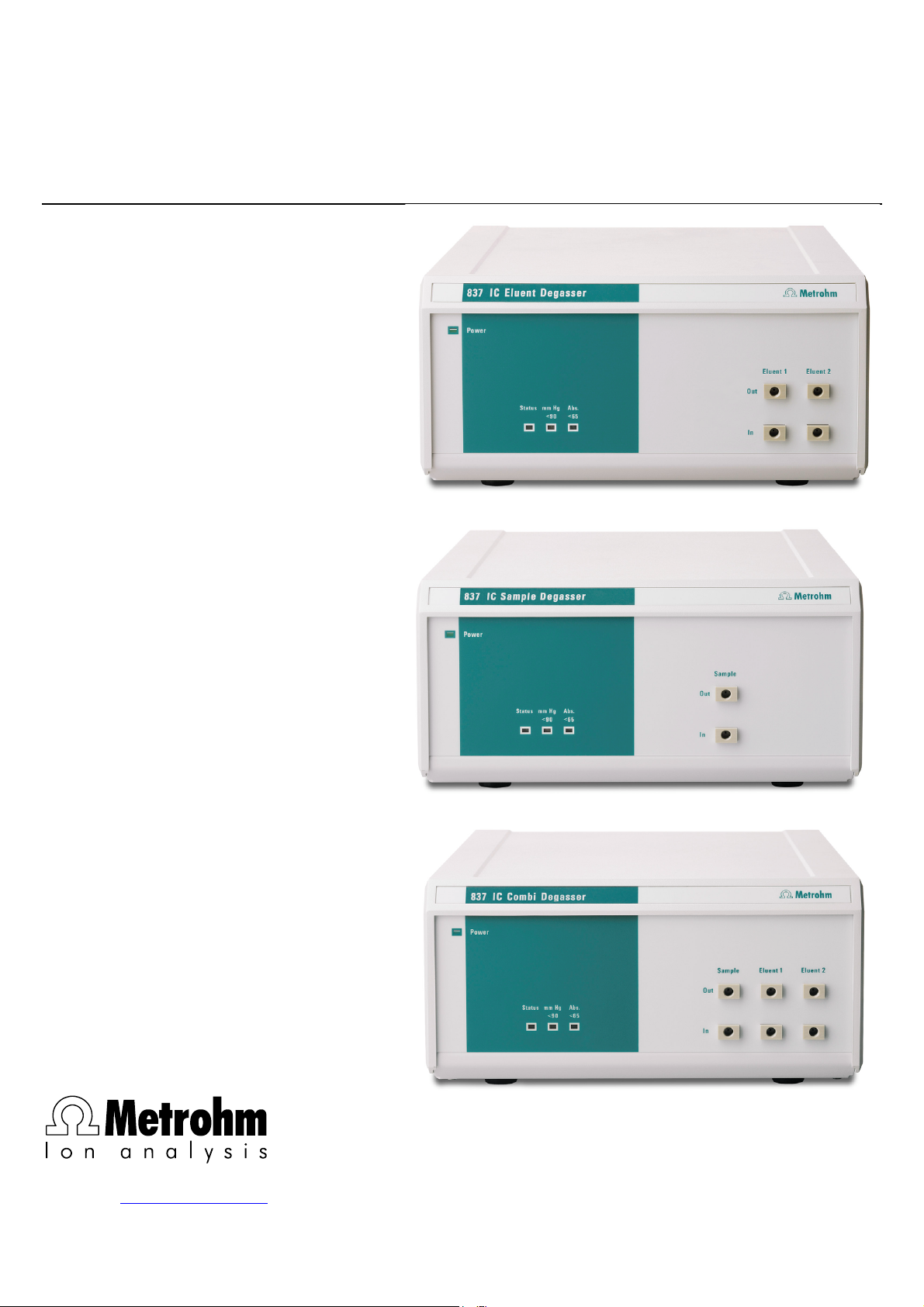
837 IC Eluent Degasser
837 IC Sample Degasser
837 IC Combi Degasser
Instructions for Use 8.837.1003
8.837.1003 02.2004 / chs
Page 4

Teachware
Metrohm AG
Oberdorfstrasse 68
CH-9101 Herisau
teachware@metrohm.com
1st Edition 2004
These instructions are protected by copyright. All rights reserved.
Although all the information given in these instructions has been checked with great care, errors
cannot be entirely excluded. Should you notice any mistakes please inform the author at the
address given above.
Page 5

Table of contents
Table of contents
1 Introduction.................................................... 1
1.1 Instrument description ............................................................. 1
1.2 Parts and controls .................................................................... 2
1.2.1 Front view 837 IC Eluent Degasser............................................... 2
1.2.2 Front view 837 IC Sample Degasser ............................................3
1.2.3 Front view 837 IC Combi Degasser ..............................................4
1.2.4 Rear view 837 IC (Eluent/Sample/Combi) Degasser.................... 5
1.3 Information about the Instructions for Use ............................. 6
1.3.1 Organization ..................................................................................6
1.3.2 Notation and pictograms ..............................................................7
1.4 Safety notes ..............................................................................8
1.4.1 Electrical safety..............................................................................8
1.4.2 General safety measures ..............................................................8
2 Installation ..................................................... 9
2.1 Instrument setup....................................................................... 9
2.1.1 Packaging...................................................................................... 9
2.1.2 Checks...........................................................................................9
2.1.3 Location ......................................................................................... 9
2.1.4 Arrangement of the instruments....................................................9
2.2 Connecting the tubing ............................................................ 10
2.2.1 Tubing connections for eluent flow path.....................................10
2.2.2 Tubing connections for sample flow path................................... 12
2.3 Connection to a modular IC system ...................................... 13
2.3.1 Electrical connection to 830 IC Interface ....................................13
2.3.2 Settings in «IC Net»......................................................................13
2.4 Connecting to the 761 Compact IC........................................ 14
2.4.1 Electrical connection to the 761 Compact IC .............................14
2.4.2 Settings for control with the «761 PC Software» .........................14
2.5 Mains connection.................................................................... 15
2.5.1 Mains voltage ..............................................................................15
2.5.2 Fuse.............................................................................................15
2.5.3 Mains cable and mains connection ............................................16
2.5.4 Switching the instrument on/off...................................................16
3 Operation...................................................... 17
3.1 General information................................................................ 17
3.2 Routine operation ................................................................... 17
3.2.1 Manual operation ........................................................................17
3.2.2 Control with «IC Net» ...................................................................17
4 Troubleshooting - Problems......................... 18
4.1 Remedying faults and problems ............................................ 18
4.2 Chromatography problems .................................................... 18
4.3 Instrument problems ..............................................................18
4.4 Carry-over with sample degassing ........................................ 19
4.4.1 Determination of the "Transfer time"............................................19
4.4.2 Check sample carry-over ............................................................19
4.5 Care and maintenance............................................................ 20
837 IC (Eluent/Sample/Combi) Degasser/ Instructions for Use 8.837.1003
I
Page 6

Table of contents
5 Appendix ....................................................... 21
5.1 Technical specifications......................................................... 21
5.2 Scope of delivery .................................................................... 23
5.2.1 2.837.0010 IC Eluent Degasser .................................................. 23
5.2.2 2.837.0020 IC Sample Degasser................................................ 24
5.2.3 2.837.0030 IC Combi Degasser .................................................25
5.3 Optional accessories .............................................................. 26
5.4 Validation / GLP ...................................................................... 27
5.5 Warranty and conformity ........................................................ 28
5.5.1 Warranty ......................................................................................28
5.5.2 Declaration of Conformity ...........................................................29
5.5.3 Quality Management Principles .................................................. 30
5.5.4 Index............................................................................................ 31
List of illustrations
Fig. 1: Front view 837 IC Eluent Degasser.................................................. 2
Fig. 2: Front view 837 IC Sample Degasser ............................................... 3
Fig. 3: Front view 837 IC Combi Degasser................................................. 4
Fig. 4: Rear view 837 IC (Eluent/Sample/Combi) Degasser....................... 5
Fig. 5: Connection of 837 IC (Eluent/Sample/Combi) Degasser to
830 IC Interface.............................................................................. 13
Fig. 6: Connecting the 837 IC (Eluent/Sample/Combi) Degasser to the
761 Compact IC............................................................................. 14
837 IC (Eluent/Sample/Combi) Degasser/ Instructions for Use 8.837.1003
II
Page 7

1.1 Instrument description
1 Introduction
1.1 Instrument description
837 IC Eluent Degasser:
The 837 IC Eluent Degasser is used for degassing eluents. Gas bubbles in eluents produce an unstable baseline as high-pressure pumps
for ion chromatography can transport liquids but not gases. This is why
eluents must be degassed before use. The degasser module is simply
included between the eluent and the IC pump. Then the eluent flows
through the special Teflon-AF
chamber. The vacuum removes small gas bubbles, and reduces the
content of solved gases like carbon dioxide or nitrogen. Timeconsuming manual eluent degassing is no longer necessary. The 837
IC Eluent Degasser is equipped with two vacuum chambers so that two
eluent flows can be degassed simultaneously.
®
-capillary, which is located in a vacuum
837 IC Sample Degasser:
The 837 IC Sample Degasser is also used for degassing samples. For
samples apply the same rules as for eluents: they cannot be injected
directly, if they either contain or release gas bubbles. The indication of
injecting samples containing gas bubbles is a poor reproducibility, because the amount of sample in the sample loop would vary. This means
that these (gas-containing) samples must be degassed before the injection. The 837 IC Sample Degasser automates the degassing. Before
the sample reaches the injection valve it passes a special Teflon-AF
capillary, which is located in a vacuum chamber. The vacuum removes
small gas bubbles, and reduces the content of solved gases like carbon dioxide or nitrogen. The 837 IC Sample Degasser is equipped with
a large-volume vacuum chamber and, for example, allows direct determination of drinks containing carbon dioxide without any manual
sample preparation.
837 IC Combi Degasser:
The 837 IC Combi Degasser is the combination of an 837 IC Eluent
Degasser and an 837 IC Sample Degasser. Both degassing of eluents
and degassing of samples can be carried out with it. The 837 IC Combi
Degasser is simply included between eluent and IC pump or between
sample and the injection valve. Eluent and sample then flow through
the special Teflon-AF
um chambers. The 837 IC Combi Degasser is equipped with a total of
three vacuum chambers so that two eluent streams and one sample
stream can be degassed simultaneously.
®
-capillaries, which are located in separate vacu-
®
-
837 IC (Eluent/Sample/Combi) Degasser/ Instructions for Use 8.837.1003
1
Page 8
1 Introduction
1.2 Parts and controls
In this section you will find the numbers and designations of the parts
and controls of the 837 IC (Eluent/Sample/Combi) Degasser. The
numbering applies throughout the instructions for use, i.e. bold numbers in the text (e.g.
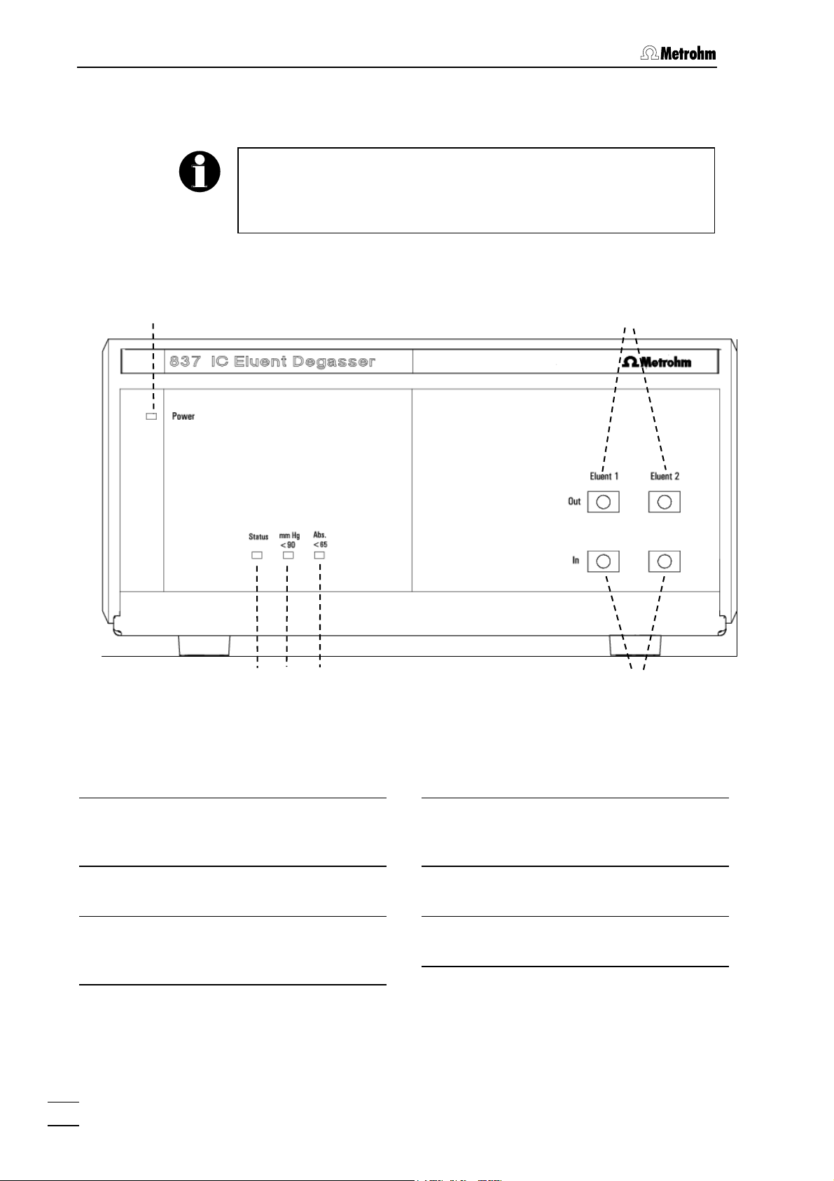
1.2.1 Front view 837 IC Eluent Degasser
3
) refer to the parts and controls illustrated here.
1
2
3
4
6
5
Fig. 1: Front view 837 IC Eluent Degasser
Mains pilot lamp
1
Lights up when instrument is switched
on.
Status - display
2
Lights up when pump is running.
mm Hg <90 - display
3
Lights up when the pressure is between 90 and 65 mm Hg.
2
837 IC (Eluent/Sample/Combi) Degasser/ Instructions for Use 8.837.1003
Abs <65 - display
4
Lights up when the pressure is below
65 mm Hg.
Inlets eluent streams
5
Inlets for 2 eluent streams.
Outlets eluent streams
6
Outlets for 2 eluent streams.
Page 9
1.2 Parts and controls
1.2.2 Front view 837 IC Sample Degasser
1
8
3
2
4
7
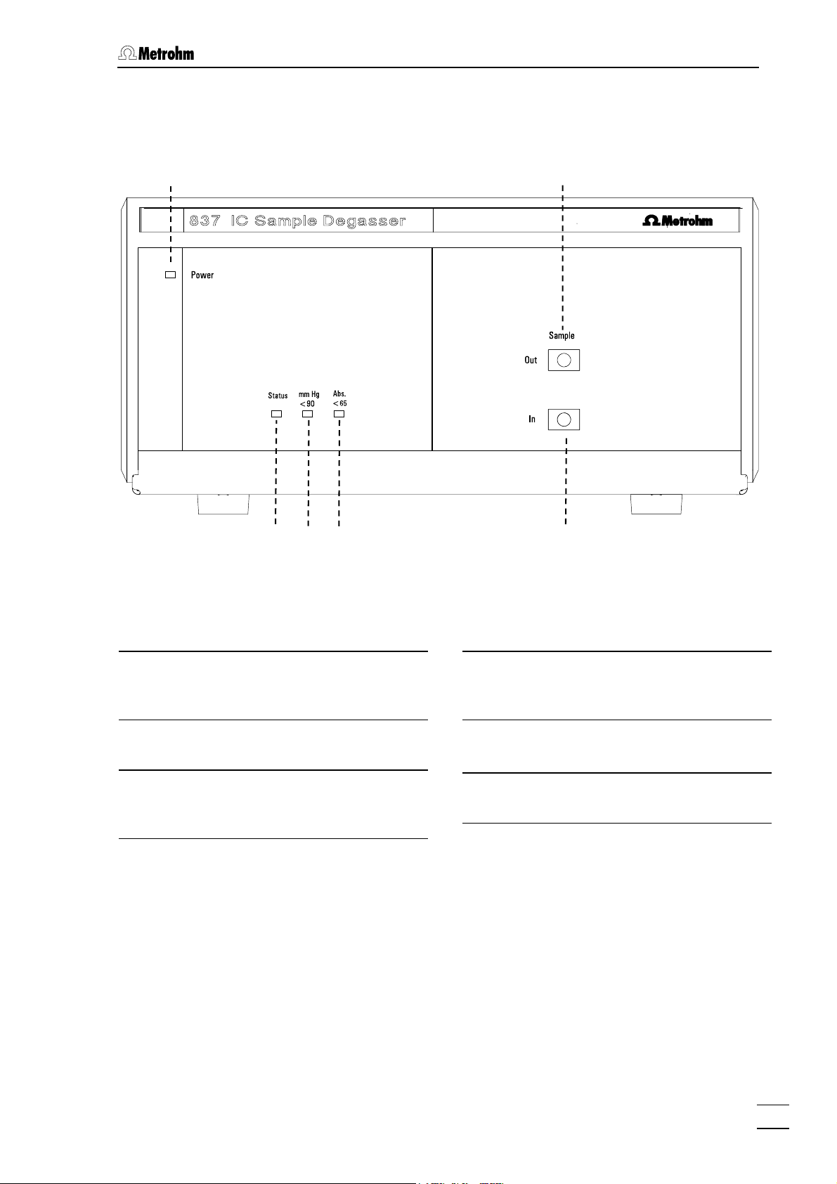
Fig. 2: Front view 837 IC Sample Degasser
Mains pilot lamp
1
Lights up when instrument is switched
on.
Status - display
2
Lights up when pump is running.
mm Hg <90 - display
3
Lights up when the pressure is between 90 and 65 mm Hg.
Abs <65 - display
4
Lights up when the pressure is below
65 mm Hg.
7
Inlet sample stream
Inlet for 1 sample stream.
Outlet sample stream
8
Outlet for 1 sample streams.
837 IC (Eluent/Sample/Combi) Degasser/ Instructions for Use 8.837.1003
3
Page 10
1 Introduction
1.2.3 Front view 837 IC Combi Degasser
1
8
2
3
4
7
6
5
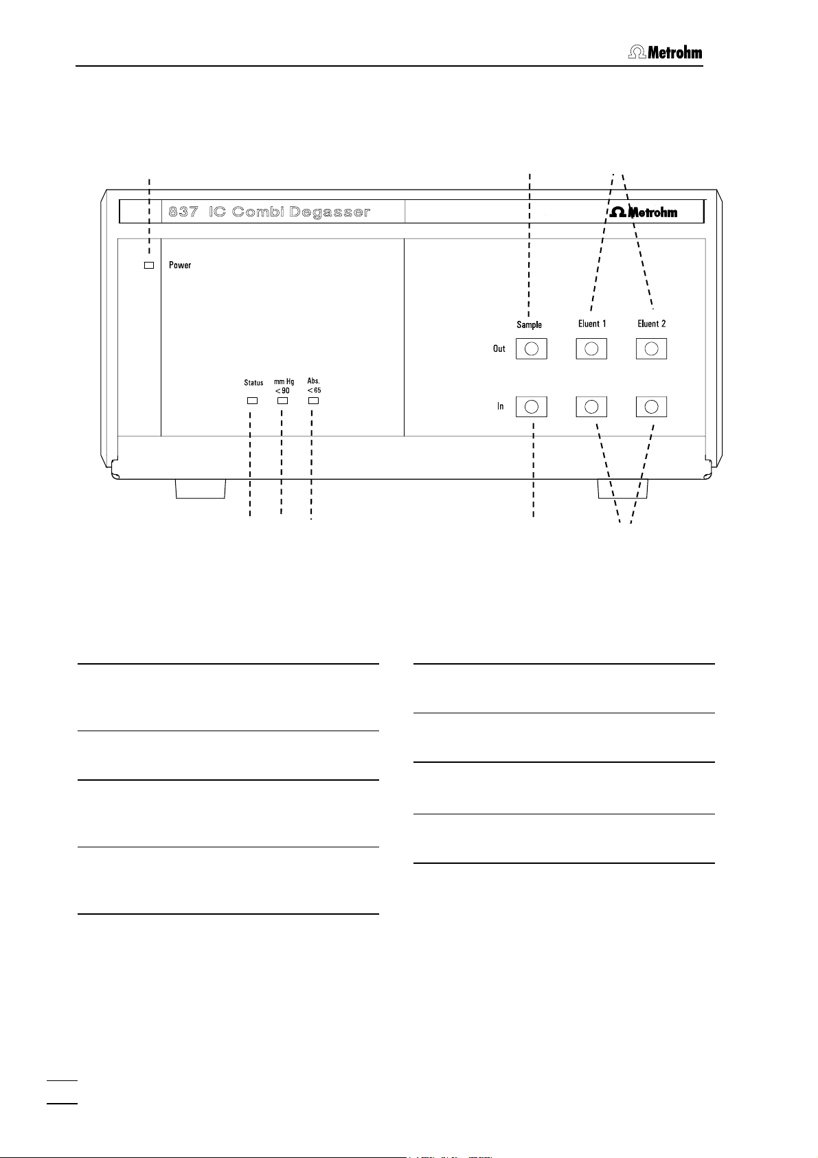
Fig. 3: Front view 837 IC Combi Degasser
Mains pilot lamp
1
Lights up when instrument is switched
on.
Status - display
2
Lights up when pump is running.
mm Hg <90 - display
3
Lights up when the pressure is between 90 and 65 mm Hg.
Abs <65 - display
4
Lights up when the pressure is below
65 mm Hg.
Inlets eluent streams
5
Inlets for 2 eluent streams.
Outlets eluent streams
6
Outlets for 2 eluent streams.
7
Inlet sample stream
Inlet for 1 sample stream.
Outlet sample stream
8
Outlet for 1 sample stream.
4
837 IC (Eluent/Sample/Combi) Degasser/ Instructions for Use 8.837.1003
Page 11
1.2 Parts and controls
1.2.4 Rear view 837 IC (Eluent/Sample/Combi) Degasser
9
10
11
12
13
15
14
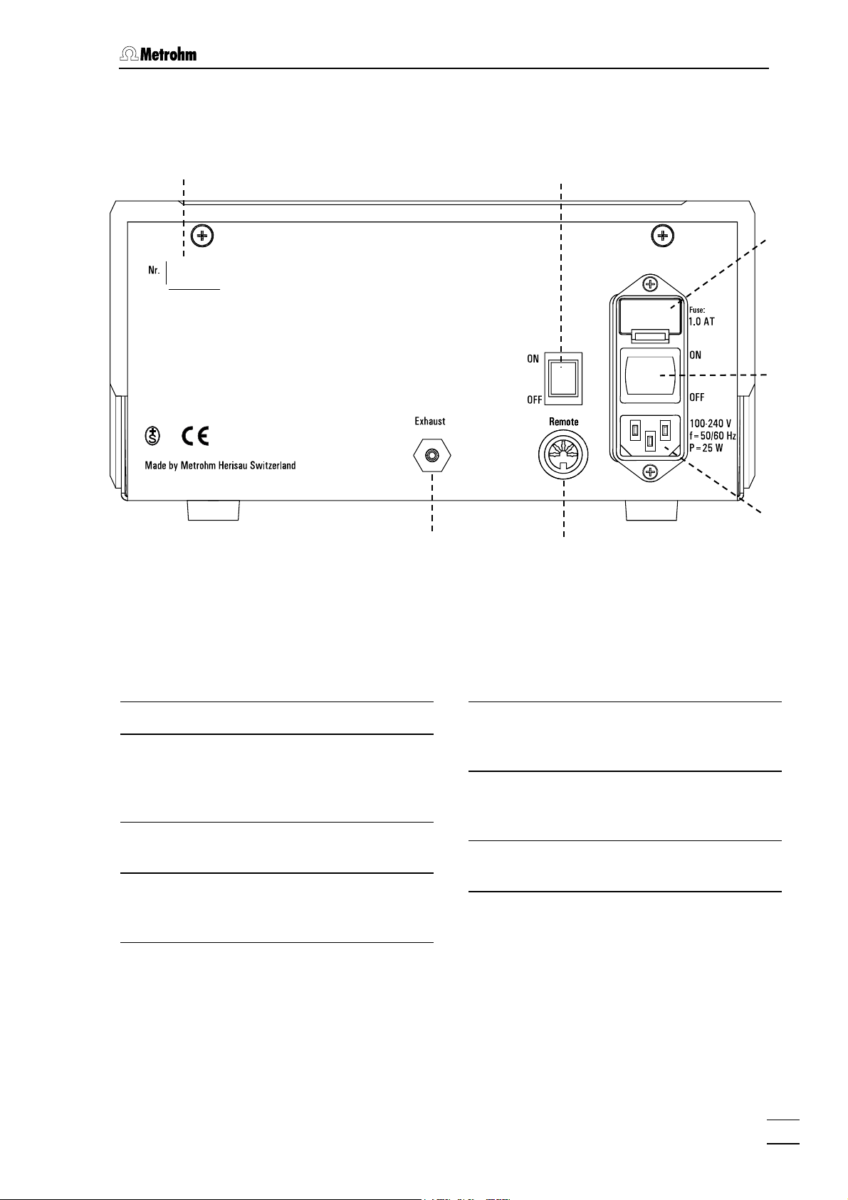
Fig. 4: Rear view 837 IC (Eluent/Sample/Combi) Degasser
Serial number
9
Remote switch
10
Activates the remote control.
ON: active
OFF: not active
Fuse holder
11
Changing the fuses, see section 2.5.2.
Mains switch
12
For switching instrument on/off:
I = ON 0 = OFF
Mains connector
13
For mains connection see section
2.5.3.
Remote-Interface
14
For connection to 830 IC Interface or to
761 Compact IC.
Exhaust opening
15
Exhaust for gases.
837 IC (Eluent/Sample/Combi) Degasser/ Instructions for Use 8.837.1003
5
Page 12
1 Introduction
1.3 Information about the Instructions for Use
Please study these Instructions for Use carefully before you start to
use the 837 IC (Eluent/Sample/Combi) Degasser. The instructions
contain information and warnings that must be observed by the user in
order to guarantee the safe use of the instrument. Please keep these
instructions near the instrument so that they are always to hand when
required.
1.3.1 Organization
These 8.837.1003 Instructions for Use for the 837 IC (Eluent/Sample/
Combi) Degasser provide you with a comprehensive overview of the installation, startup, troubleshooting and technical specifications of the
instrument. The instructions are arranged as follows:
Section 1 Introduction
General description of the instrument, operating parts
and controls, and safety notes.
Section 2 Installation
Installation of the instrument, tubing connections,
electrical connections, mains connection.
Section 3 Operation
General instructions, controls.
Section 4 Troubleshooting - Problems
Possible faults and their remedies, maintenance.
Section 5 Appendix
Technical data, standard equipment, optional accessories, warranty and declaration of conformity, index.
In order to find the information you require about the 837 IC (Eluent/Sample/Combi) Degasser, you should either use the Contents or
the Index.
6
837 IC (Eluent/Sample/Combi) Degasser/ Instructions for Use 8.837.1003
Page 13

1.3 Information about the Instructions for Use
1.3.2 Notation and pictograms
The following notation and pictograms (symbols) are used in these Instructions:
7 Parts and controls
Danger/Warning
This symbol indicates a possible
risk of death or injury to the user
and possible damage to the
instrument or its components by
electricity.
Danger/Warning
This symbol indicates a possible
risk of death or injury to the user
and possible damage to the instrument or its components.
Attention
This symbol indicates important information that you should read before continuing.
Information
This symbol indicates additional information and tips which may be of
particular use to you.
837 IC (Eluent/Sample/Combi) Degasser/ Instructions for Use 8.837.1003
7
Page 14

1 Introduction
1.4 Safety notes
1.4.1 Electrical safety
Electrical safety when handling the 837 IC (Eluent/Sample/Combi) Degasser is guaranteed within the scope of Standard IEC/EN 61010-1
(protection class 1, degree of protection IP30). However, please observe the following points:
• Mains connection
Set the mains voltage and check the mains fuse and mains connection in accordance with the instructions in section 2.5.
• Opening the instrument
Inside the instrument there are no parts which must be set or adjusted
by the user.
The instrument may only be opened by specialized staff of Metrohm. If
the 837 IC (Eluent/Sample/Combi) Degasser is connected to the
mains supply then it must neither be opened nor should any parts be
removed from it, as otherwise the risk of contact with current-carrying
assemblies exists. This is why the instrument should be separated
from all voltage sources before being opened. Please make sure that
the mains cable is pulled out from mains connector 13!
• Protection against electrostatic charges
Electronic components are sensitive to electrostatic charges and can
be destroyed by a discharge. Before touching any assembly within
the 837 IC (Eluent/Sample/Combi) Degasser you should ground yourself and any tool you are using by grasping a grounded object (e.g.
the instrument housing or a radiator) in order to eliminate any electrostatic charge which may be present.
1.4.2 General safety measures
• Liquid handling
Check all inlet and outlet tubing for leaks at regular intervals. Observe
the appropriate regulations concerning the handling of flammable
and/or toxic solutions and their disposal.
8
837 IC (Eluent/Sample/Combi) Degasser/ Instructions for Use 8.837.1003
Page 15

2.1 Instrument setup
2 Installation
2.1 Instrument setup
2.1.1 Packaging
The 837 IC (Eluent/Sample/Combi) Degasser and its specially packed
accessories are supplied in very protective special packaging which
contains a shock-absorbing plastic foam lining. The instrument itself is
contained in a dustproof evacuated polyethylene bag. Please store this
packaging in a safe place; it is the only way in which the safe transport
of the instrument can be guaranteed.
2.1.2 Checks
Please check that the delivery is complete and undamaged
immediately on receipt (compare with delivery note and list of
accessories given in section 5.2). If transport damage is evident please
refer to the information given in section 5.5.1 "Warranty".
2.1.3 Location
Place the instrument on a suitable vibration-free laboratory bench, protected as much as possible from corrosive atmospheres and contact
with chemicals.
To avoid disturbing temperature influences on the insulated column
compartment, the pump and eluent reservoir must be protected
against direct sunlight.
2.1.4 Arrangement of the instruments
The 837 IC (Eluent/Sample/Combi) Degasser should preferably be at
the bottom of the IC System (If you use it together with the 833 IC Liquid
Handling Unit: Place the 837 directly above the 833).
The 837 IC (Eluent/Sample/Combi) Degasser should always be
placed at the bottom of the instrument stack so that any leaks which
may occur in the pump tubing or connections cannot cause damage
to the other instruments by leakage liquids.
837 IC (Eluent/Sample/Combi) Degasser/ Instructions for Use 8.837.1003
9
Page 16

2 Installation
2.2 Connecting the tubing
The tubing connections for eluent flow paths and sample flow paths are
different.
The tubing connections should be kept as short as possible. Cut the
tubings to the lengths required by your system. To get a perfectly flat
cut surface it is best to use the Capillary tubing cutter 6.2621.080.
2.2.1 Tubing connections for eluent flow path
To install the tubing connections for eluent degassing (with 837 IC Eluent Degasser or 837 IC Combi Degasser) proceed as follows:
1 Take down filter mount and clamping screw
To enable the insertion of the aspiration tubing 6.1834.020 (16)
through the cover of the eluent bottle, the filter mount (17) and
the clamping screw (18) have to be removed from the tubing
end. Loosening the filter mount (17) makes both parts movable.
16
17
18
2 Insert aspiration tubing top down through the si-
phon of the eluent bottle
Put tube nipple (M8 thread) and O-ring of the eluent bottle siphon on the released tubing end of the aspiration tubing
6.1834.020 (16). Then insert that tubing end top down through
the siphon of the eluent bottle, and tighten the tube nipple.
3 Screw aspiration filter onto filter mount
Screw the aspiration filter 6.2821.090 (19) onto the filter mount
(17).
19
4 Put clamping screw back on the aspiration tubing
Put the clamping screw (18) back on the aspiration tubing.
17
10
837 IC (Eluent/Sample/Combi) Degasser/ Instructions for Use 8.837.1003
Page 17

2.2 Connecting the tubing
5 Insert aspiration tubing into aspiration filter and
screw together
Insert the aspiration tubing with clamping screw (18) through the
filter mount (17) into the aspiration filter 6.2821.090 (19). Screw
filter mount (17) and clamping screw (18) together until they are
fixed to the aspiration tubing. The tubing end should contact the
bottom of the aspiration filter, to prevent the formation of an air
cushion. Proceed as follows:
• Place the aspiration filter with attached
filter mount on a flat surface.
• Insert the aspiration tubing with
clamping screw top down into the
aspiration filter, until the tubing end
contacts the bottom of the filter.
• Screw filter mount and clamping screw
together.
6 Attach aspiration tubing to degasser
Screw the other end of the aspiration tubing (with pressure
screw and flange) to an Eluent Inlet In (5) of the degasser (Initially, screw it in loosely by hand, then tighten it by using the
wrench ¼" 6.2621.050 (also included in the standard equipment)
to rotate the screw a further ¼ turn).
7 Connect degasser with pump
To connect degasser and pump, the tubing connection
6.1834.030 is used. Screw the tubing end with pressure screw
and flange to the corresponding Eluent Outlet Out (6) of the
degasser (Initially, screw it in loosely by hand, then tighten it by
using the wrench ¼" 6.2621.050 (also included in the standard
equipment) to rotate the screw a further ¼ turn). Connect the
other end with the pump.
Aspiration tube for eluent
16
(6.1834.020)
Tube to aspirate the eluent.
Filter mount
17
Mount, where the aspiration filter
6.2821.090 is screwed on.
837 IC (Eluent/Sample/Combi) Degasser/ Instructions for Use 8.837.1003
Clamping screw of aspiration tub-
18
ing
Can be fixed to the aspiration tubing by
tightening the filter mount.
Aspiration filter (6.2821.090)
19
Filters the eluent when aspirating.
11
Page 18

2 Installation
2.2.2 Tubing connections for sample flow path
To install the tubing connections for degassing of samples (with 837 IC
Sample Degasser or 837 IC Combi Degasser) proceed as follows:
1 Connect sample changer with degasser
To connect sample changer and degasser, a connection tubing
6.1834.050 is used. The tube end with the clamping screw is
connected via PEEK Coupling 6.2744.030 or 6.2744.034 to the
pump tubing of the peristaltic pump (see Instructions for Use of
the sample changer). Screw the other tube end with the pressure screw and the flange to the Sample Inlet In (7) of the degasser (Initially, screw it in loosely by hand, then tighten it by using the wrench ¼" 6.2621.050 (also included in the standard
equipment) to rotate the screw a further ¼ turn).
2 Connect degasser with injection valve
To connect degasser and injection valve, another connection
tubing 6.1834.050 is used. Screw the tube end with the pressure
screw and the flange to the corresponding Sample Outlet Out
(8) of the degasser (Initially, screw it in loosely by hand, then
tighten it by using the wrench ¼" 6.2621.050 (also included in
the standard equipment) to rotate the screw a further ¼ turn).
Screw the other end with the clamping screw to the injection
valve.
After installation is a good moment for the determination of the "Transfer time" of the sample flow (The time the sample needs to flow from
the sample changer through the degasser till the end of the sample
loop), see section 4.4.1. The "Transfer time" is important to know for
the determination of the rinsing time – the longer the "Transfer time" is,
the longer the rinsing time should be.
837 IC (Eluent/Sample/Combi) Degasser/ Instructions for Use 8.837.1003
12
Page 19

2.3 Connection to a modular IC system
2.3 Connection to a modular IC system
To use the 837 IC (Eluent/Sample/Combi) Degasser in a modular ICsystem connect it via an 830 IC Interface.
2.3.1 Electrical connection to 830 IC Interface
Always switch off the 837 IC (Eluent/Sample/Combi) Degasser before
making new electrical connections.
The 837 IC (Eluent/Sample/Combi) Degasser is normally integrated
into the modular IC system via 830 IC Interface. Connect the remoteinterface (14) of the degasser with a free event line at the 830 IC Interface using the cable 6.2128.180 according to the figure below. To activate the communication between the 830 IC Interface and the 837 IC
(Eluent/Sample/Combi) Degasser, the remote-switch (10) on the Degasser must be set to ON.
Fig. 5: Connection of 837 IC (Eluent/Sample/Combi) Degasser to 830 IC
Interface
One cable 6.2128.180 is needed for each remote-connection. At the
830 IC Interface, connections can be established in two systems with 7
lines each. It doesn’t matter which event lines are used for this, you just
need to allocate them correctly when setting up the system in the software «IC Net» (see also section 6.1 of the «IC Net 2.3» Software-
Manual).
2.3.2 Settings in «IC Net»
Add the device to the system, as described in section 6.1 of the «IC Net
2.3» Software-Manual. The settings and control elements for the Degas-
ser in the «IC Net» are described in section 6.21 of the «IC Net 2.3» Software-Manual.
837 IC (Eluent/Sample/Combi) Degasser/ Instructions for Use 8.837.1003
13
Page 20

2 Installation
2.4 Connecting to the 761 Compact IC
The installation of the 837 IC (Eluent/Sample/Combi) Degasser with the
761 Compact IC, and its control with the «761 PC Software» software is
described below.
2.4.1 Electrical connection to the 761 Compact IC
Always switch off the 837 IC (Eluent/Sample/Combi) Degasser before
making new electrical connections.
The electrical connections of the system consisting of the 761 Compact
IC and the 837 IC (Eluent/Sample/Combi) Degasser are made according to the following figure. To activate the communication between the
761 Compact IC and 837 IC (Eluent/Sample/Combi) Degasser, the remote-switch (10) on the Degasser must be set to ON.
761
837
6.2143.210
6.2134.100
PC
Fig. 6: Connecting the 837 IC (Eluent/Sample/Combi) Degasser
to the 761 Compact IC
The remote-cable 6.2143.210 has a two-headed end with two DINplugs. The end C (labeled at the end of the cable) should be used for
the Degasser. The end B is only needed, if an 828 IC Dual Suppressor
is connected simultaneously.
2.4.2 Settings for control with the «761 PC Software»
Is the 837 IC (Eluent/Sample/Combi) Degasser connected to the 761
Compact IC via end C of the remote-cable 6.2143.210 as described
above, the value for Remote Line 2 in the software «761 PC Software»
must be set to 1 (see Instructions for Use 761 Compact IC).
837 IC (Eluent/Sample/Combi) Degasser/ Instructions for Use 8.837.1003
14
Page 21

2.5 Mains connection
2.5 Mains connection
Please observe the following rules when connecting the instrument to
the electricity supply. If the instrument is operated with an incorrectly
set mains voltage and/or an incorrect mains fuse then it represents a
fire hazard!
2.5.1 Mains voltage
All power supplies from 100 V to 240 V with 50/60 Hz can be connected
to the mains input of the 837 IC (Eluent/Sample/Combi) Degasser.
Adaptation to the mains supply used is carried out automatically.
2.5.2 Fuse
A 1.0 A fuse (slow blow) is contained in the fuse holder (11) of the 837
IC (Eluent/Sample/Combi) Degasser.
Make sure that the instrument is never operated with a different type of
fuse as otherwise it represents a fire hazard!
Changing the fuse
1 Pull out mains cable
Switch off the instrument and remove the mains cable from
mains supply connection (13) of the 837 IC (Eluent/Sample/Combi) Degasser.
2 Remove the fuse holder
Use a screwdriver to loosen the fuse holder beside the mains
supply connection (see Fig. 4) and remove it completely.
3 Changing the fuse
Change the fuse if necessary and replace it in the fuse holder.
Use only a fuse with the following specifications:
1.0 A fuse (slow blow) Metrohm-No. U.600.0016
4 Re-insert fuse holder
837 IC (Eluent/Sample/Combi) Degasser/ Instructions for Use 8.837.1003
15
Page 22

2 Installation
2.5.3 Mains cable and mains connection
Mains cable
The instrument is supplied with one of the following mains cables
6.2122.020 with SEV 12 plug (Switzerland, …)
6.2122.040 with CEE(7), VII plug (Germany, …)
6.2133.070 with NEMA 5-15 plug (USA, …)
which has three wires and is fitted with a plug with a grounding pin. If a
different plug has to be used then the yellow/green wire (IEC standard)
must be connected to the grounding pin (Protection class I).
Any interruption to the grounding inside or outside the instrument can
represent a hazard!
Mains connection
Insert the mains cable into mains connector 13 of the 837 IC (Eluent/Sample/Combi) Degasser.
2.5.4 Switching the instrument on/off
The 837 IC (Eluent/Sample/Combi) is switched on and off with mains
switch 12. When the instrument is switched on, the "Power" 1 LED
lights up.
837 IC (Eluent/Sample/Combi) Degasser/ Instructions for Use 8.837.1003
16
Page 23

3.1 General information
3 Operation
3.1 General information
• The vacuum pump works at two levels. The first level is used
to generate the vacuum, the second level to maintain it.
• The display mm Hg <90 lights up orange if the pressure is
between 65 and 90 mm Hg.
• The display Abs <90 lights up green, if the pressure is below
65 mm Hg. This is the normal working status, and should be
reached a few seconds after switching on the pump.
• The display Status lights up green, if the pump is switched on.
A new 837 IC (Eluent/Sample/Combi) Degasser device needs a certain running-in period to reach the optimal performance. Therefore all
chambers should be run with eluent (for eluent flow paths) resp. ultrapure water (for sample flow paths) for one night before using it the
first time.
3.2 Routine operation
3.2.1 Manual operation
If you want to operate the Degasser manually, proceed as follows:
1 Installation
Install the 837 IC (Eluent/Sample/Combi) Degasser as described
in section 2.
2 Deactivate the remote-connection
Set the remote-switch 10 to OFF. The remote-connection is deactivated that way.
3 Switch on/off pump
Set the mains switch 12 to I to switch on the pump and to 0 to
switch it off again.
3.2.2 Control with «IC Net»
If you want to control the degasser with «IC Net», install it as described
in section 2.3. The control via «IC Net» is described in section 6.21 of
the «IC Net 2.3» Software-Manual.
837 IC (Eluent/Sample/Combi) Degasser/ Instructions for Use 8.837.1003
17
Page 24

4 Troubleshooting - Problems
4 Troubleshooting - Problems
4.1 Remedying faults and problems
If difficulties occur during analyses with your IC system then it is best to
search for their causes in the following sequence: column → pump →
eluent → IC system. In the "Instructions for Use" of your Modular IC
system or 761 Compact IC you will find an overview of possible faults
together with their causes and remedies.
In addition to these general problems, the following section covers
those problems which could arise from the use of the 837 IC (Eluent/Sample/Combi) Degasser.
4.2 Chromatography problems
Instrument Problem Cause Remedy
Sample/Combi Degasser (Sample flow path
used)
2.837.0020
2.837.0030
Eluent/Combi Degasser (Eluent flow path
used)
2.837.0010
2.837.0030
Some peaks larger/smaller than ex-
pected
Peaks smaller than
expected
Poor retention time
reproducibility
Noisy or unstable
baseline
• Carry-over of sample
from the previous measurement
• Leak in system (Sample
flow path)
• Blockage in the flow
path (Sample flow path)
• Leak in system (Eluent
flow path)
• Blockage in the flow
path (Eluent flow path)
• Leak in system (Eluent
flow path)
• Blockage in the flow
path (Eluent flow path)
• Extend rinsing time between two
samples, see section 4.4
• Check if liquid is leaking from
the exhaust opening 15. If yes,
contact Metrohm Service.
• Contact Metrohm Service
• Check if liquid is leaking from
the exhaust opening 15. If yes,
contact Metrohm Service.
• Siehe Kap.4.3.
• Check if liquid is leaking from
the exhaust opening 15. If yes,
contact Metrohm Service.
• Contact Metrohm Service
4.3 Instrument problems
Problem Cause Remedy
LED "Power" 1 does not
light up (Mains switch 12 on
I )
837 IC (Eluent/Sample/Combi) Degasser/ Instructions for Use 8.837.1003
18
• Mains cable not connected
• Fuse blown
• Electronics fault
• Connect the Degasser to the mains sup-
ply
• Replace fuse, see section 2.5.2
• Contact Metrohm Service
Page 25

4.4 Carry-over with sample degassing
Liquid is leaking from the
exhaust opening (15)
LED "Abs <65" (4) does not
light up (while pump is run-
ning)
• Leak in the instrument • Contact Metrohm Service
• Leak in vacuum chamber
• Vacuum pump does not work
properly
• Contact Metrohm Service
• Contact Metrohm Service
4.4 Carry-over with sample degassing
If you work with sample degassing (837 IC Sample/Combi Degasser),
you should rinse longer (with the succeeding sample) because of the
longer "Transfer time" (The time the sample needs to flow from the sample vial through the degasser till the end of the sample loop). The rinse
time should be at least 2-3 longer than the "Transfer time", to minimize
carry-over effects. The "Transfer time" itself depends on pumping
capacity, total capillary volume and volume of the gas removed by the
degasser (thus on the amount of gas in the sample).
4.4.1 Determination of the "Transfer time"
To determine the "Transfer time", the system (pump tube, tubing connections, Degasser capillary, sample loop) should be emptied. Pump
air through the system for some minutes, until all liquid is displaced by
air. Then, aspirate a typical (for your later application) sample, and
measure the time the sample needs to flow from the sample vial till the
end of the sample loop. The migration of the top of the sample flow can
be observed with the eye. The measured time is the "Transfer time". The
rinse time should be at least 2-3 times longer (Check carry-over, see
section 4.4.2).
4.4.2 Check sample carry-over
Sample carry-over and required rinsing time can be checked by spiking
a sample with an ion (which is not or only in small amounts contained
by the original sample); for example phosphate for mineral water samples. Procedure:
1. Prepare two samples:
a. Sample A: a sample, typical for your application
b. Sample B: Sample A - spiked with a "Spike-Ion"
2. Let sample A flow through the sample flow path (for the duration
of the rinsing time), inject it and measure
3. Let then flow sample B through the sample flow path (for the duration of the rinsing time), inject it and measure
4. Then let again sample A flow through the sample stream (for the
duration of the rinsing time), inject it and measure
The ratio of the peak area of the "Spike-Ion" in the second measurement
of sample A to the peak area in the measurement of sample B reflects
the extend of the sample carry-over. The smaller that ratio is, the
837 IC (Eluent/Sample/Combi) Degasser/ Instructions for Use 8.837.1003
19
Page 26

4 Troubleshooting - Problems
smaller is the sample carry-over. You can change that ratio by varying
the rinsing time – and hence identify the rinsing time needed for your
application.
4.5 Care and maintenance
Instrument care
The 837 IC (Eluent/Sample/Combi) Degasser requires adequate care.
Excessive contamination of the instrument could interfere with its functions and reduce the working life of the really robust mechanism and
electronics.
Spilt chemicals and solvents should be removed immediately. The connections on the rear panel (and the mains connection in particular)
should be protected against contamination.
Although the design prevents liquid penetration to a great extent, if
aggressive media should enter the housing then pull out the mains
plug of the 837 IC (Eluent/Sample/Combi) Degasser immediately, in
order to prevent massive damage to the instrument’s electronics. In
such a case please contact the Metrohm Service Department.
The instrument may only be opened by specialized staff of Metrohm.
Maintenance by Metrohm Service
The maintenance of the 837 IC (Eluent/Sample/Combi) Degasser
should take place within the framework of an annual service carried out
by trained Metrohm technicians. If work is frequently performed with
caustic and corrosive chemicals, it may be necessary to shorten the interval between servicing.
The Metrohm service department is always willing to offer expert advice
on the maintenance and servicing of all Metrohm instruments.
837 IC (Eluent/Sample/Combi) Degasser/ Instructions for Use 8.837.1003
20
Page 27

5.1 Technical specifications
5 Appendix
5.1 Technical specifications
Vacuum
Pressure range < 65 mm Hg
Generation time after start < 30 s
Capillary in the degasser
Capillary volume Eluent: 195 µL
Material Teflon AF
Solvent stability Excellent stability against most solvents (Excep-
Ambient temperature
Provided that nothing to the contrary is mentioned, the
published data are typical values for the 837 IC (Eluent/Sample/Combi) Degasser at an ambient temperature of 25°C.
Sample: 670 µL
tion: PFCs)
Nominal operating range +5..+45 °C (at max. 85 % atmospheric humidity)
Storage -40...+70 °C
Transport -40...+70 °C
Mains connection
Voltage 100…240 V (± 10%)
Frequency 50...60 Hz
Power consumption 25 W
Fuses 5 mm Ø, 20 mm long
1.0 AT (slow blow); must only be replaced by the
same type.
Safety specifications
Construction and testing According to IEC/EN 61010-1 / UL 3101-1,
degree of protection IP30
Safety directions This "Instructions for Use" include information and
warnings which must be heeded by the user to
assure safe operation of the instrument.
837 IC (Eluent/Sample/Combi) Degasser/ Instructions for Use 8.837.1003
21
Page 28

5 Appendix
Electromagnetic compatibility (EMC)
Emitted interference Standards met:
- IEC/EN 61326
- EN 55022
- CISPR 22
Immunity to interference Standards met:
- IEC/EN 61326
- IEC/EN 61000-4-2
- IEC/EN 61000-4-3
- IEC/EN 61000-4-4
- IEC/EN 61000-4-5
- IEC/EN 61000-4-6
- IEC/EN 61000-4-8
- IEC/EN 61000-4-11
- IEC/EN 61000-4-14
- NAMUR
Housing
Cover material Rigid polyurethane foam (PUR) with flame protec-
tion to flammability class UL94VO, CFC-free
Base material Steel, enameled
Width 260 mm
Height 129 mm
Depth 366 mm
Weight
837 IC Eluent Degasser:
837 IC Sample Degasser:
837 IC Combi Degasser:
4204 g
4149 g
4214 g
837 IC (Eluent/Sample/Combi) Degasser/ Instructions for Use 8.837.1003
22
Page 29

5.2 Scope of delivery
5.2 Scope of delivery
We reserve the right to make alterations!
All dimensions given in mm.
5.2.1 2.837.0010 IC Eluent Degasser
The 2.837.0010 IC Eluent Degasser includes the following parts:
No. Order. no. Description
1 1.837.0010 IC Eluent Degasser
2 6.1834.020 Aspiration tubing to 837
(made of PTFE, with connector for aspiration filter 6.2821.090)
Length = 1.5 m,
i.d. = 1.5 mm, o.d. = 2.5 mm
For the connection:
837 Eluent inlet – Eluent bottle
2 6.1834.030 Tubing connection 837- High pres-
sure pump
(made of PTFE)
Length = 0.5 m,
i.d. = 1.5 mm, o.d. = 2.5 mm
For the connection:
837 Eluent outlet - High pressure pump
1 6.2128.180 Remote connection cable
Connection cable:
830 IC Interface - 837 IC Degasser
1 6.2621.050 Wrench ¼"
1 6.2821.090 Aspiration filter
pore size 20 µm
For aspiration tubing 6.1834.020.
Set of 5 pieces.
1 6.2122.0X0 Mains cable to customer’s requirements:
Cable socket
Type IEC 320/C 13 Type SEV 12 (CH…) 6.2122.020
Type IEC 320/C 13 Type CEE (7), VII (D…) 6.2122.040
Type CEE (22), V Type NEMA 5-15 (USA) 6.2122.070
1 8.837.1003 Instructions for Use (English)
for 837 IC (Eluent/Sample/Combi) Degasser
Cable plug
∅9
35
837 IC (Eluent/Sample/Combi) Degasser/ Instructions for Use 8.837.1003
23
Page 30

5 Appendix
5.2.2 2.837.0020 IC Sample Degasser
The 2.837.0020 IC Sample Degasser includes the following parts:
No. Order. no. Description
1 1.837.0020 IC Sample Degasser
2 6.1834.050 Tubing connection 837 for sample
flow
(made of PTFE)
Length = 2.0 m
i.d. = 1.5 mm, o.d. = 2.5 mm
For the connections:
837 Sample inlet – Peristaltic tube of
the sample changer
and
837 Sample outlet – Injection valve
1 6.2128.180 Remote connection cable
Connection cable:
830 IC Interface - 837 IC Degasser
1 6.2621.050 Wrench ¼"
1 6.2744.014 PEEK pressure screw
For connecting 1⁄16" capillaries.
set of 2 pieces.
1 6.2122.0X0 Mains cable to customer’s requirements:
Cable socket
Type IEC 320/C 13 Type SEV 12 (CH…) 6.2122.020
Type IEC 320/C 13 Type CEE (7), VII (D…) 6.2122.040
Type CEE (22), V Type NEMA 5-15 (USA) 6.2122.070
1 8.837.1003 Instructions for Use (English)
for 837 IC (Eluent/Sample/Combi) Degasser
Cable plug
26
837 IC (Eluent/Sample/Combi) Degasser/ Instructions for Use 8.837.1003
24
Page 31

5.2 Scope of delivery
5.2.3 2.837.0030 IC Combi Degasser
The 2.837.0030 IC Combi Degasser includes the following parts:
No. Order. no. Description
1 1.837.0030 IC Combi Degasser
2 6.1834.020 Aspiration tubing to 837
(made of PTFE, with connector for
6.2821.090 aspiration filter)
Length = 1.5 m,
i.d. = 1.5 mm, o.d. = 2.5mm
For the connection:
837 Eluent inlet – Eluent bottle
2 6.1834.030 Tubing connection 837- High pres-
sure pump
(made of PTFE)
Length = 0.5 m,
i.d. = 1.5 mm, o.d. = 2.5 mm
For the connection:
837 Eluent outlet - High pressure pump
2 6.1834.050 Tubing connection 837 for sample
flow
(made of PTFE)
Length = 2.0 m
i.d. = 1.5 mm, o.d. = 2.5mm
For the connections:
837 Sample inlet – Peristaltic tube of
the sample changer
and
837 Sample outlet – Injection valve
1 6.2128.180 Remote connection cable
Connection cable:
830 IC Interface - 837 IC Degasser
1 6.2621.050 Wrench ¼"
1 6.2744.014 PEEK pressure screw
For connecting 1⁄16" capillaries.
Set of 2 pieces.
26
837 IC (Eluent/Sample/Combi) Degasser/ Instructions for Use 8.837.1003
25
Page 32

5 Appendix
No. Order. no. Description
1 6.2821.090 Aspiration filter
pore size 20 µm
For aspiration tubing 6.1834.020.
Set of 5 pieces.
1 6.2122.0X0 Mains cable to customer’s requirements:
Cable socket
Type IEC 320/C 13 Type SEV 12 (CH…) 6.2122.020
Type IEC 320/C 13 Type CEE (7), VII (D…) 6.2122.040
Type CEE (22), V Type NEMA 5-15 (USA) 6.2122.070
1 8.837.1003 Instructions for Use (english)
for 837 IC (Eluent/Sample/Combi) Degasser
Cable plug
5.3 Optional accessories
Order. no. Description
6.2143.210 Connection cable
761 Compact IC – 837 IC (Eluent/Sample/Combi) Degasser
DIN Plug C (labeled at the end of the cable)
should be used for the Degasser (C is con-
nected with Remote Line 2 of the Compact IC
761).
Connect other devices via DIN Plug B.
∅9
35
6.2621.080 Capillary cutter for plastic capillaries
with 5 spare cutting blades.
55
118
837 IC (Eluent/Sample/Combi) Degasser/ Instructions for Use 8.837.1003
26
Page 33

5.4 Validation / GLP
5.4 Validation / GLP
GLP (Good Laboratory Practice) requires, among other things, that the
precision and correctness of analytical instruments is checked at regular intervals by using SOPs (Standard Operating Procedures, SOP). An
example of such a standard operating procedure is available from
Metrohm under the title «Application Bulletin No. 277 – Validation of
Metrohm Ion Chromatography Systems by using Standard Operating Procedures (SOP)». This SOP can be adapted for your ion
chromatography system and used for its validation.
The 837 IC (Eluent/Sample/Combi) Degasser must be included as a
part of the whole ion chromatography system, whose most important
components include the pumps, separation columns, detector and
evaluation system, in the all-embracing validation of the whole system.
Please contact your local Metrohm agency in order to receive support
in validating your 837 IC (Eluent/Sample/Combi) Degassers. It can also
provide you with validation documentation which will help you to carry
out your installation qualification (IQ) and operational qualification (OQ).
Further information about QA, GLP and validation can also be found in
the brochure «Quality management with Metrohm» which is also obtainable from your local Metrohm agency.
Checking the electronic and mechanical assemblies of Metrohm instruments can and should be undertaken within the framework of regular servicing by Metrohm technicians. All Metrohm instruments are
equipped with start-up check routines which check that the relevant assemblies are functioning perfectly when the instrument is switched on. If
no error message appears it can be assumed that the instrument is
functioning properly.
The 837 IC (Eluent/Sample/Combi) Degasser also contains a built-in
diagnosis program which allows the service technicians to check the
functioning of particular assemblies should faults or malfunctions occur
and to localize them.
837 IC (Eluent/Sample/Combi) Degasser/ Instructions for Use 8.837.1003
27
Page 34

5 Appendix
5.5 Warranty and conformity
5.5.1 Warranty
The warranty on our products is limited to defects that are traceable to
material, construction or manufacturing error which occur within 12
months from the day of delivery. In this case the defects will be rectified
in our workshops free of charge. Transport costs are to be paid by the
customer.
For day and night operation the warranty is limited to 6 months.
Glass breakage in the case of electrodes or other parts is not covered
by the warranty. Checks which are not a result of material or manufacturing faults are also charged during the warranty period. For parts from
outside manufacturers, insofar as these constitute an appreciable part
of our instrument, the warranty stipulations of the manufacturer in question apply.
With the regard to the guarantee of accuracy the technical specifications in the instruction manual are authoritative.
Concerning defects in materials, construction or design as well as the
absence of guaranteed features the purchaser has no rights or claims
except those mentioned above.
If damage of the packaging is evident on receipt of a consignment or if
the goods show signs of transport damage after unpacking, the carrier
must be informed immediately and a written damage report demanded.
Lack of an official damage report releases Metrohm from any liability to
pay compensation.
If any instruments and parts have to be returned then the original packaging should be used if at all possible. This applies above all to instruments, electrodes, buret cylinders and PTFE pistons. Before embedment in wood shavings or similar material the parts must be packed in
a dustproof package (for instruments the use of a plastic bag is essential). If open assemblies are included that are sensitive to electromagnetic voltages (e.g. data interfaces, etc.) then these must be returned in
the associated original protective packaging (e.g. conductive protective
bag). (Exception: assemblies with a built-in voltage source belong in
non-conductive protective packaging).
For damage which arises as a result of non-compliance with these instructions no warranty responsibility whatsoever will be accepted by
Metrohm.
837 IC (Eluent/Sample/Combi) Degasser/ Instructions for Use 8.837.1003
28
Page 35

5.5 Warranty and conformity
5.5.2 Declaration of Conformity
This is to certify the conformity to the standard specifications for electrical appliances and accessories, as well
as to the standard specifications for security and to system validation issued by the manufacturing company.
Name of commodity 837 IC (Eluent/Sample/Combi) Degasser
Name of manufacturer Metrohm Ltd., Herisau, Switzerland
Description
2.837.0010 IC Eluent Degasser
Instrument for the continuous degassing of two eluent streams.
2.837.0020 IC Sample Degasser
Instrument for the continuous degassing of a sample stream.
2.837.0030 IC Combi Degasser
Instrument for the continuous degassing of two eluent streams and one sample stream.
CH-9101 Herisau, Switzerland
Tel. +41 71 353 85 85
Fax +41 71 353 89 01
www.metrohm.com
This Metrohm instrument has been built and has undergone final type testing according to the standards:
Electromagnetic compatibility: Emission
IEC/EN 61326, EN 55022 / CISPR 22
Electromagnetic compatibility: Immunity
IEC/EN 61326, IEC/EN 61000-4-2, IEC/EN 61000-4-3, IEC/EN 61000-4-4, IEC/EN 61000-4-5, IEC/EN
61000-4-6, IEC/EN 61000-4-8, IEC/EN 61000-4-11, IEC/EN 61000-4-14, NAMUR
Safety specifications
IEC/EN 61010-1, UL 3101-1 protection class I
It has also been certified by ElectroSuisse, which is member of the International Certification Body
(CB/IEC).
The instrument meets the requirements of the CE mark as contained in the EU directives 89/336/EEC
and 73/23/EEC and fulfils the following specifications:
EN 61326 Electrical equipment for measurement, control and laboratory use – EMC requirements
EN 61010-1 Safety requirements for electrical equipment for measurement, control and laboratory
use
Metrohm Ltd. is holder of the SQS-certificate of the quality system ISO 9001 for quality assurance in
design/development, production, installation and servicing.
The technical specifications are documented in the instruction manual.
The instruments were validated with respect to functionality, analytical performance and accuracy of
results. The instrument functions are documented in the instruction manual.
Herisau, March 13, 2003
Dr. J. Frank Ch. Buchmann
Development Manager Production and
Quality Assurance Manager
837 IC (Eluent/Sample/Combi) Degasser/ Instructions for Use 8.837.1003
29
Page 36

5 Appendix
5.5.3 Quality Management Principles
Metrohm Ltd., CH-9101 Herisau, Switzerland
CH-9101 Herisau/Switzerland
E-Mail info@metrohm.com
Internet www.metrohm.com
Metrohm Ltd. holds the ISO 9001 Certificate, registration number 10872-02, issued by
SQS (Swiss Association for Quality and Management Systems). Internal and external audits are carried out periodically to assure that the standards defined by Metrohm’s QM
Manual are maintained.
The steps involved in the design, manufacture and servicing of instruments are fully
documented and the resulting reports are archived for ten years. The development of
software for PCs and instruments is also duly documented and the documents and
source codes are archived. Both remain the possession of Metrohm. A non-disclosure
agreement may be asked to be provided by those requiring access to them.
The implementation of the ISO 9001
quality system is described in Metrohm’s
QM Manual, which comprises detailed
instructions on the following fields of
activity:
Instrument development
The organisation of the instrument design, its planning and the intermediate
controls are fully documented and traceable. Laboratory testing accompanies all
phases of instrument development.
Software development
Software development occurs in terms of
the software life cycle. Tests are performed to detect programming errors
and to assess the program’s functionality in a laboratory environment.
Components
All components used in the Metrohm
instruments have to satisfy the quality
standards that are defined and implemented for our products. Suppliers of
components are audited by Metrohm as
the need arises.
Manufacture
The measures put into practice in the
production of our instruments guarantee
a constant quality standard. Production
planning and manufacturing procedures,
maintenance of production means and
testing of components, intermediate and
finished products are prescribed.
Customer support and service
Customer support involves all phases of
instrument acquisition and use by the
customer, i.e. consulting to define the
adequate equipment for the analytical
problem at hand, delivery of the equipment, user manuals, training, after-sales
service and processing of customer
complaints. The Metrohm service organisation is equipped to support customers in implementing standards such
as GLP, GMP, ISO 900X, in performing
Operational Qualification and Performance Verification of the system components or in carrying out the System Validation for the quantitative determination
of a substance in a given matrix.
837 IC (Eluent/Sample/Combi) Degasser/ Instructions for Use 8.837.1003
30
Page 37

5.5 Warranty and conformity
5.5.4 Index
830 IC Interface
Electrical connection ................. 13
Abs <65 - display 4
Figure................................... 2, 3, 4
Accessories ................................... 26
Ambient temperature .................... 21
Appendix ....................................... 21
Arrangement of the instruments ..... 9
Aspiration filter
Ordering number................. 23, 25
Aspiration filter 19 ......................... 11
Aspiration tube (6.1834.020) for
eluent 16........................................ 11
Aspiration tubing
Ordering designation .......... 23, 25
Attention........................................... 7
Cable
6.2128.180............... 13, 23, 24, 25
6.2143.210........................... 14, 26
761 - 837.............................. 14, 26
Capillary cutter 6.2621.080 ..... 10, 26
Care ............................................... 20
CE mark......................................... 29
Checks............................................. 9
Clamping screw of aspiration tubing
18................................................... 11
Conformity ..................................... 28
Connecting the tubing................... 10
Connection
To 830 IC Interface .................... 13
To a modular IC system ............ 13
To the 761 Compact IC ............. 14
To the PC................................... 13
Contents ........................................... I
Control
With «IC Net» ............................. 17
With the «761 PC Software» ...... 14
Danger............................................. 7
Declaration of Conformity ............. 29
Degree of protection ................. 8, 21
Electrical connection
To the 830 IC Interface............. 13
To the 761 Compact IC ............. 14
Electrical safety ............................... 8
Electromagnetic compatibility....... 22
Electrostatic charges....................... 8
EMC ............................................... 22
Emitted interference ...................... 22
Error remedies............................... 18
Exhaust opening 15
Figure........................................... 5
Filter mount 17 .............................. 11
Flow ............................................... 21
Front view
837 IC Combi Degasser ............. 4
837 IC Eluent Degasser .............. 2
837 IC Sample Degasser ............ 3
Fuse............................................... 15
Fuse holder 11
Changing the fuse ..................... 15
Figure..................................... 5, 15
Fuses
Technical specifications ............21
General information ....................... 17
General safety measures ................ 8
GLP ..........................................27, 30
GMP ............................................... 30
Grounding.................................. 8, 16
Grounding pin................................ 16
Guarantee ...................................... 28
Housing.......................................... 22
Illustrations
List................................................ II
Immunity to interference ................ 22
Information....................................... 7
Operation ................................... 17
Information about the Instructions for
Use................................................... 6
Inlet sample stream
Figure....................................... 3, 4
Inlets eluent streams
Figure....................................... 2, 4
Installation........................................ 9
Instrument care.............................. 20
Instrument description..................... 1
Instrument setup.............................. 9
Introduction...................................... 1
IQ.................................................... 27
ISO 9100 ........................................ 29
Leaks............................................ 8, 9
Liquid handling ................................8
List of illustrations ............................ II
Location ...........................................9
Mains
Cable.......................................... 16
Connection ................................ 15
Switching the instrument on/off. 16
Voltage....................................... 15
Mains cable
Ordering number ...........23, 24, 26
Mains connection ......................8, 16
Technical specifications ............21
Mains connector 13
Figure........................................... 5
Mains frequency ............................21
Mains pilot lamp 1
Figure.............................2, 3, 4, 16
Mains switch 12
Figure........................................... 5
Mains voltage
Technical specifications ............21
Maintenance ..................................20
Manual operation........................... 17
Metrohm Service............................ 20
mm Hg <90 - display 3
Figure................................... 2, 3, 4
Notation ........................................... 7
Opening the instrument ................... 8
Operation ....................................... 17
Manual .......................................17
Optional accessories..................... 26
OQ.................................................. 27
Organization .................................... 6
7
5
Outlet sample stream
Figure .......................................3, 4
Outlets eluent streams
Figure .......................................2, 4
Packaging ........................................9
Parts and controls............................2
Pictograms .......................................7
Power consumption .......................21
Pressure range............................... 21
Problems ........................................18
Protection class .........................8, 16
QA ..................................................27
Quality assurance ..........................27
Quality Management .....................30
Rear view.......................................... 5
Remote
Cable....................... 13, 23, 24, 25
Remote switch 10
Figure ...........................................5
Remote-Interface 14
Figure ...........................................5
Return transport ...............................9
Routine operation ..........................17
Safety
Specifications............................. 21
Safety notes .....................................8
Scope of delivery ...........................23
Serial number
Figure ...........................................5
Settings
Mains voltage.............................15
Solvent stability ..............................21
SOP ................................................27
Standard operating procedures ....27
Status-display
Figure ................................... 2, 3, 4
Storage........................................... 21
Sunlight ............................................9
Switching the instrument on/off .....16
Technical specifications ................21
Transfer ..........................................12
Transport damage .....................9, 28
Troubleshooting .........................6, 18
Tubing connection 837- High
pressure pump
Ordering designation ...........23, 25
Tubing connections
Eluent flow path .........................10
Sample flow path .......................12
Ordering designation ...........24, 25
Vacuum ..........................................21
Generation time after start .........21
Validation........................................27
Voltage ...........................................15
Warning ............................................ 7
Warranty ......................................... 28
Wrench ¼"................................11, 12
Order number ................23, 24, 25
8
6
9
2
837 IC (Eluent/Sample/Combi) Degasser/ Instructions for Use 8.837.1003
31
 Loading...