

Page 1

CH-9101 Herisau/Switzerland
E-Mail info@metrohm.com
Internet www.metrohm.com
Titrando
Installation Instructions
8.840.1133 06.2006 / jb
Page 2

Teachware
Metrohm AG
Oberdorfstrasse 68
CH-9101 Herisau
teachware@metrohm.com
These instructions are protected by copyright. All rights reserved.
Although all the information given in these Instructions has been checked with great care, errors
cannot be entirely excluded. Should you notice any mistakes please inform the author at the
address given above.
Page 3

Contents
Table of contents
1 Introduction.......................................................... 1
1.1 Instrument description...................................................................................2
1.2 Information about the Installation Instructions............................................3
1.2.1 Organization .............................................................................................3
1.2.2 Notation and pictograms .........................................................................4
1.3 Parts and controls..........................................................................................5
1.4 Safety notes....................................................................................................8
1.4.1 Electrical safety.........................................................................................8
2 Installation ........................................................... 9
2.1 Overview ...................................................................................................... 10
2.2 Instrument setup ......................................................................................... 11
2.2.1 Packaging...............................................................................................11
2.2.2 Checks....................................................................................................11
2.2.3 Location ..................................................................................................11
2.3 Controller connection ................................................................................. 11
2.3.1 Touch Control connection......................................................................12
2.3.2 Computer connection.............................................................................13
2.4 Device connection at the MSB ................................................................... 14
2.4.1 Connecting stirrers and titration stands.................................................15
2.4.2 Attaching the exchange unit to the Titrando ..........................................16
2.4.3 Connecting an external dosing device ..................................................18
2.4.4 Connecting a remote box.......................................................................20
2.5 Device connection at the USB.................................................................... 21
2.5.1 Connecting a printer...............................................................................21
2.5.2 Connecting a balance ............................................................................22
2.5.3 Connecting a USB Sample Processor / Robotic Titrosampler..............24
2.5.4 Connecting additional Titrandos or Dosing Interfaces ..........................24
2.5.5 Connecting a PC keyboard (Titrando with Touch Control only)............25
2.5.6 Connecting a barcode reader................................................................25
2.5.7 Connecting a USB hub ..........................................................................26
2.5.8 Connecting a Bluetooth® adapter ..........................................................26
2.6 Sensor connection ...................................................................................... 29
2.6.1 Connecting an 854 iConnect .................................................................29
2.6.2 Differential potentiometry .......................................................................30
2.6.3 Titration vessel setup..............................................................................30
2.6.4 Assembly of the Karl Fischer titration cell ..............................................31
2.7 Update of the instrument software............................................................. 32
3 Troubleshooting ................................................. 33
3.1 Problems...................................................................................................... 33
4 Appendix ............................................................. 35
4.1 Technical data ............................................................................................. 35
4.1.1 Titration and measuring modes .............................................................35
4.1.2 Measuring interfaces..............................................................................35
Titrando Installation Instructions I
Page 4

Contents
4.1.3 Specification of the measuring inputs ...................................................36
4.1.4 Specification of the measuring inputs (857 only) ..................................36
4.1.5 Internal dosing device............................................................................37
4.1.6 Interfaces................................................................................................37
4.1.7 Mains connection...................................................................................37
4.1.8 Safety specifications ..............................................................................38
4.1.9 Electromagnetic compatibility (EMC) ....................................................38
4.1.10 Ambient temperature .............................................................................38
4.1.11 Reference conditions .............................................................................38
4.1.12 Dimensions ............................................................................................39
4.1.13 Recycling and disposal.......................................................................... 39
4.2 Standard equipment.................................................................................... 40
4.2.1 808 Titrando ...........................................................................................40
4.2.2 809 Titrando ...........................................................................................41
4.2.3 835 Titrando ...........................................................................................42
4.2.4 836 Titrando ...........................................................................................43
4.2.5 841 Titrando ...........................................................................................44
4.2.6 842 Titrando ...........................................................................................45
4.2.7 857 Titrando ...........................................................................................46
4.3 Additional instruments and optional accessories .................................... 47
4.3.1 Controller for operating the Titrando......................................................47
4.3.2 Stirrers and titration stands ....................................................................47
4.3.3 Titration equipment ................................................................................47
4.3.4 Karl Fischer titration equipment 6.5609.000..........................................48
4.3.5 Dosing devices.......................................................................................49
4.3.6 Combined pH electrodes.......................................................................50
4.3.7 Combined metal electrodes ..................................................................50
4.3.8 Ion-sensitive electrodes and surfactant electrodes............................... 50
4.3.9 Karl Fischer electrodes ..........................................................................51
4.3.10 Reference electrodes .............................................................................51
4.3.11 Temperature sensors ............................................................................. 51
4.3.12 Cables for electrodes and other accessories........................................ 52
4.3.13 Communication......................................................................................52
4.3.14 Cables for balances ...............................................................................53
4.4 Warranty and conformity ............................................................................ 54
4.4.1 Warranty .................................................................................................54
4.4.2 Declaration of Conformity for 808 Titrando ...........................................55
4.4.3 Declaration of Conformity for 809 Titrando ...........................................56
4.4.4 Declaration of Conformity for 835 Titrando ...........................................57
4.4.5 Declaration of Conformity for 836 Titrando ...........................................58
4.4.6 Declaration of Conformity for 841 Titrando ...........................................59
4.4.7 Declaration of Conformity for 842 Titrando ...........................................60
4.4.8 Declaration of Conformity for 857 Titrando ...........................................61
4.4.9 Quality Management Principles .............................................................62
5 Index ................................................................... 63
II Titrando Installation Instructions
Page 5

Contents
List of illustrations
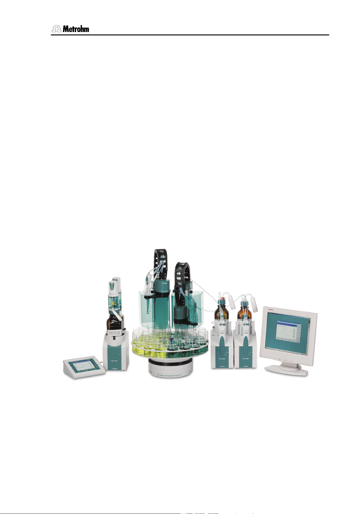
Fig. 1: The Titrando system ...................................................................................................... 1
Fig. 2: Front view of a Titrando with internal dosing drive ........................................................ 5
Fig. 3: Front view of a Titrando for the use of external dosing devices ................................... 6
Fig. 4: Rear view of the Titrando ...............................................................................................7
Fig. 5: Titrando – Peripheral devices ........................................................................................ 9
Fig. 6: Titrando – Touch Control ............................................................................................. 12
Fig. 7: Titrando – Computer .................................................................................................... 13
Fig. 8: Overview of MSB connections..................................................................................... 14
Fig. 9: Titrando – Stirrer........................................................................................................... 15
Fig. 10: Attaching the exchange unit to the Titrando ............................................................. 16
Fig. 11: Example for connecting a dosing device: Titrando – 800 Dosino ........................... 18
Fig. 12: Example for connecting a dosing device: Titrando – 805 Dosimat......................... 19
Fig. 13: Titrando – Remote box .............................................................................................. 20
Fig. 14: Titrando – Printer........................................................................................................ 21
Fig. 15: Titrando – USB-RS232 box – Balance....................................................................... 23
Fig. 16: Titrando –USB Sample Processor ............................................................................. 24
Fig. 17: Titrando – Titrando/Dosing Interface ......................................................................... 24
Fig. 18: Titrando – Sensors .....................................................................................................29
Fig. 19: Connecting the 854 iConnect .................................................................................... 29
Fig. 20: Recommended arrangement of magnetic stirring bar (1), electrode (2) and
buret tip (3) ...................................................................................................................30
Fig. 21: Drawing of the KF titration cell 6.5609.000................................................................ 31
Fig. 22: Arrangement of transport tip, buret tip and draw-off tip ........................................... 32
Titrando Installation Instructions III
Page 6

Contents
IV Titrando Installation Instructions
Page 7
1 Introduction
1 Introduction
These installation instructions provide you with a comprehensive overview of the installation and specifications of the Titrando system. The
Titrando is the centerpiece of the modular Titrando system. Operation is
carried out either via a Touch Control with touch-sensitive screen
("stand-alone" titrator) or from a computer via the USB connection and
using the PC software PC Control or tiamo.
A Titrando system can integrate several, different devices. With PC
Control/Touch Control, up to three control devices (Titrandos, Dosing
Interfaces, USB Sample Processors, etc.) can be controlled via USB
connection. The tiamo software allows to expand the system with practically any number of control devices. The control devices have three to
four MSB connections (MSB = Metrohm Serial Bus), to which peripheral devices can be connected. These are mainly dosing drives
(700/800 Dosinos and 685/805 Dosimats), stirrers and titration stands,
etc.
Figure 1 shows you the flexibility of the Titrando system. On the left a Titrando is shown with external dosing devices operated by the Touch
Control. To the right of it you can see an automation system consisting
of a USB Sample Processor, a Titrando with internal dosing drive and a
Dosimat operated by the PC Control software.
Fig. 1: The Titrando system
Titrando Installation Instructions 1
Page 8

1.1 Instrument description
Additional information about the Titrando system can be found on the
Internet under www.titrando.com
Information about specific applications can be found in our "Applica-
tion Bulletins" and "Application Notes"; these can be obtained free
of charge from your local Metrohm agency or downloaded from the
Internet under www.metrohm.com.
jects of titration techniques and electrodes are also available.
.
Various monographs on the sub-
1.1 Instrument description
The Titrandos differ mainly from the kind of dosing drive. They are
equipped either with an internal dosing drive for an exchange unit (type
806 or previous) or for the use of external dosing devices (700 and 800
Dosinos with 807 dosing units).
Common features of the Titrando:
• A connection for Touch Control or for a computer with PC software
PC Control or tiamo.
• Four MSB connections (Metrohm Serial Bus) each controlling one
dosing device (Dosimat with exchange unit or Dosino with dosing
unit), a stirrer or titration stand and a remote box.
• One or two measuring interfaces. A measuring interface consists of
a high-impedance measuring input for pH, redox or ISE sensors, an
input for a separate reference electrode, a measuring input for temperature sensors (Pt1000 or NTC) and a measuring input for polarized electrodes.
• Two USB connections allow to connect, for example, a printer, keyboard, barcode reader or additional control devices (USB Sample
Processor, Titrando, Dosing Interface, etc.).
2 Titrando Installation Instructions
Page 9
1 Introduction
1.2 Information about the Installation Instructions
Attention!
Please study these Installation Instructions carefully before you start to
use the Titrando. The instructions contain information and warnings
that must be observed by the user in order to guarantee the safe use
of the instrument. Please keep these instructions near the instrument
so that they are always to hand when required.
1.2.1 Organization
These Installation Instructions for the Titrandos provide you with a comprehensive overview of the installation, startup, troubleshooting and
technical specifications of the instruments.
The Installation Instructions are arranged as follows:
Introduction
General description of the instrument, operating elements and safety information
Installation
Installation of the instrument, connection of the peripheral devices and
accessories
Troubleshooting
Description of possible errors and how to remedy them
Appendix
Technical data, standard equipment, optional accessories, warranty
and declaration of conformity
Index
In order to find the information you require about the Titrando you
should either use the Table of contents or the Index.
Titrando Installation Instructions 3
Page 10
1.2 Information about the Installation Instructions
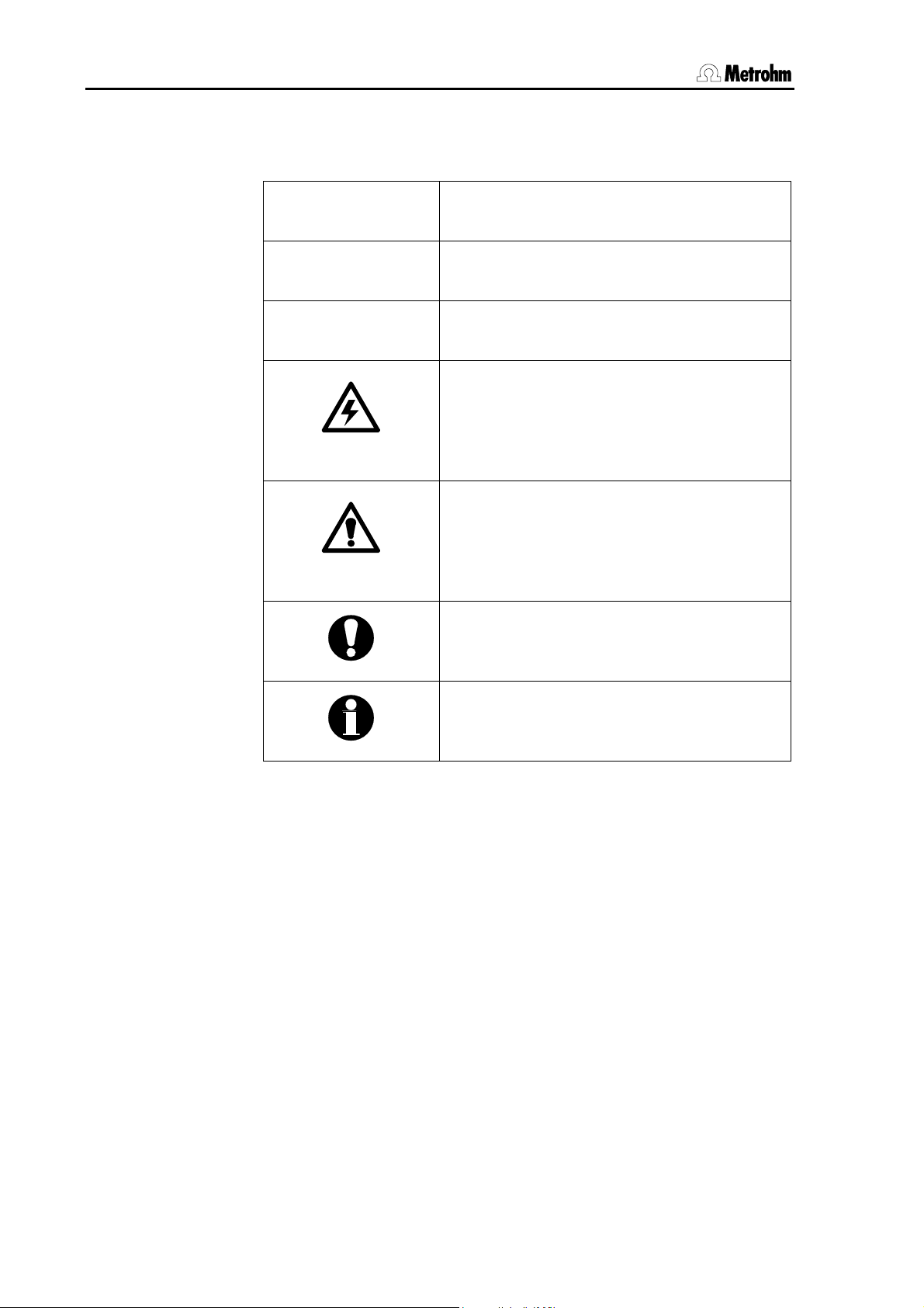
1.2.2 Notation and pictograms
The following notation and pictograms are used in these Instructions:
9
[Continue]
Control element, instrument element
see illustrations in Section 1.3
Instruction
Carry out the instructions step by step.
Button
on the user interface
Danger
This symbol indicates a possible risk of
death or injury to the user and possible
damage to the instrument or its components by electricity.
Warning
This symbol indicates a possible risk of
damage to the instrument or its components if the given information is not properly
observed.
Attention
This symbol indicates important information
that you should read before continuing.
Information
This symbol indicates additional information
and tips that may be particularly useful.
4 Titrando Installation Instructions
Page 11
1 Introduction
1.3 Parts and controls
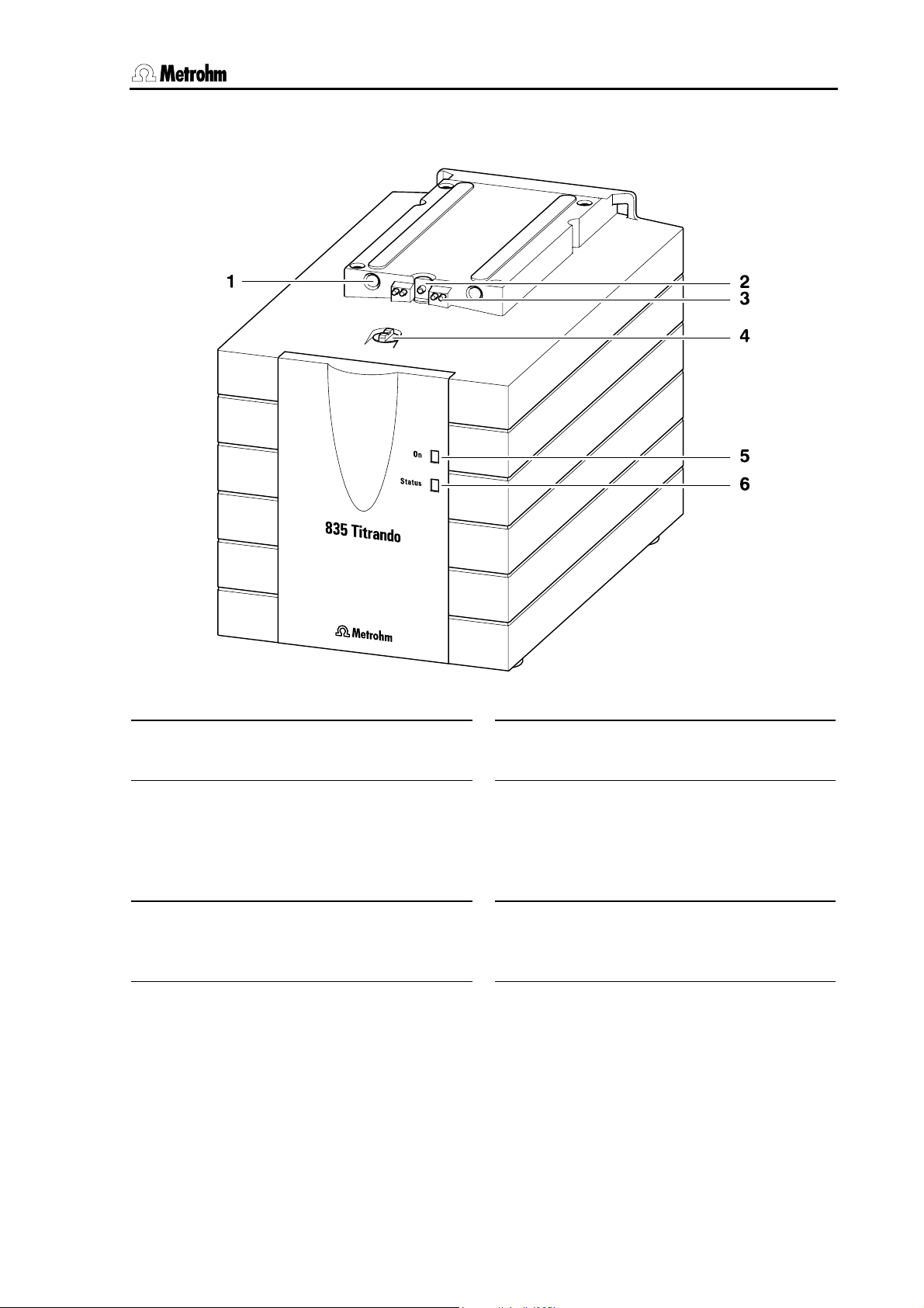
Fig. 2: Front view of a Titrando with internal dosing drive
1 Guide openings
for centering the exchange unit
2 Push rod
of the dosing drive
3 Contact pins
for the data chip
4 Coupling
for switching the flat cock
5 "On" LED
Lights up when the Titrando is connected to the mains supply and a controller (Touch Control or computer) is
connected and switched on.
6 "Status" LED
Shows the current status of the internal
dosing drive (see Section 2.4.2).
Titrando Installation Instructions 5
Page 12
1.3 Parts and controls
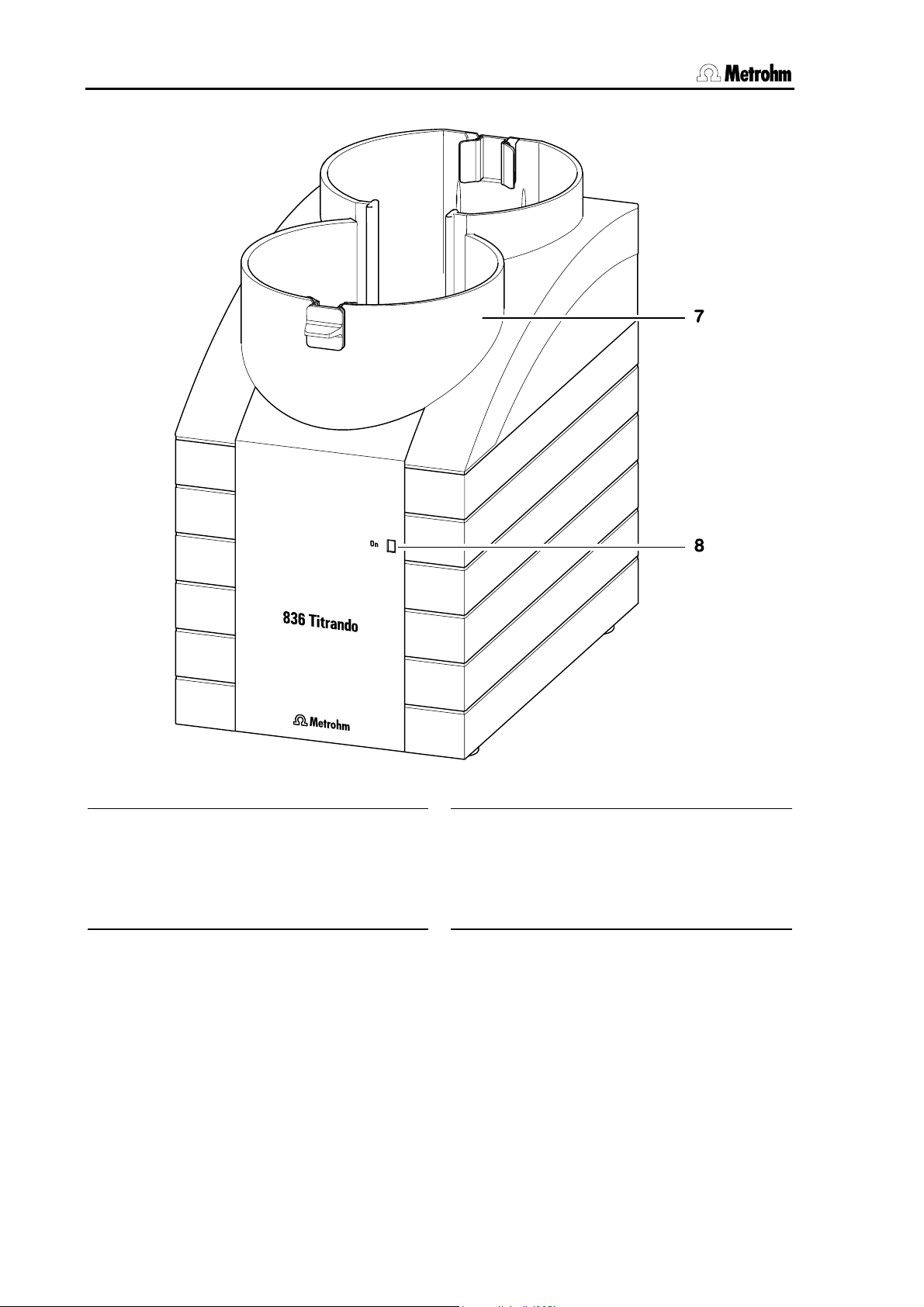
Fig. 3: Front view of a Titrando for the use of external dosing devices
7 Bottle holder
with holding clips, for two reagent bottles
8 "On" LED
Lights up when the Titrando is connected to the mains supply and a controller (Touch Control or computer) is
connected and switched on.
6 Titrando Installation Instructions
Page 13
1 Introduction
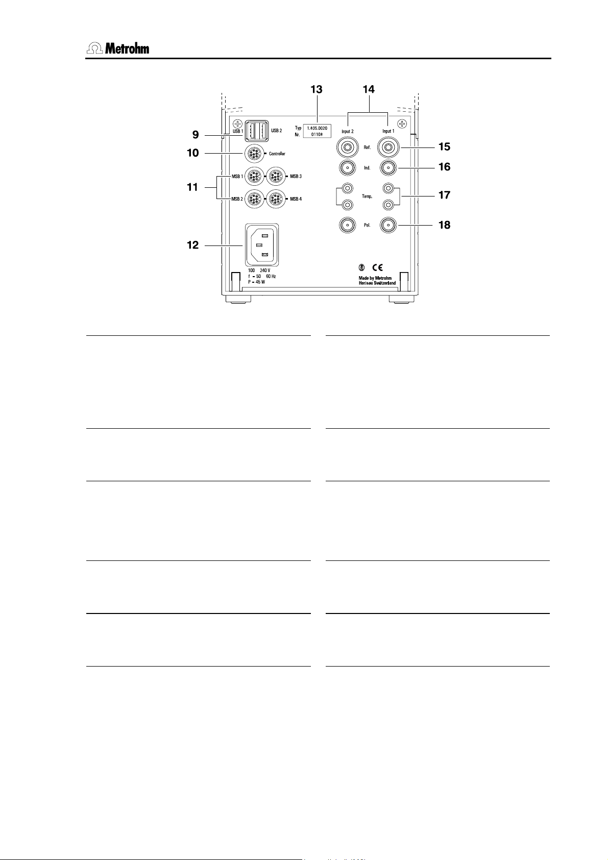
Fig. 4: Rear view of the Titrando
9 USB connections USB 1 and USB 2
USB ports (type A) for connection of
printer, keyboard, barcode reader, additional Titrandos, USB Sample Processor, etc.
10 Controller connection
Connection for Touch Control or PC
with installed PC software
11 MSB connections MSB 1 to MSB 4
Metrohm Serial Bus
Connection for external dosing device,
stirrer or remote box
12 Mains connection socket
Mains connection
13 Instrument type and serial number
14 Measuring interface 1 (Input 1) and
Measuring interface 2 (Input 2)
Models 2.8XX.0010: 1 measuring interface,
Models 2.8XX.0020: 2 measuring interfaces
15 Connection for reference electrode
(Ref.)
e. g. Ag/AgCl reference electrode
16 High-impedance measuring input
(Ind.)
Connection of pH, redox or ISE sensors with built-in or separate reference
electrode
17 Connection for temperature sen-
sors (Temp.)
Pt1000 or NTC
18 Measuring input for polarized elec-
trodes (Pol.)
e. g. double Pt electrodes
Titrando Installation Instructions 7
Page 14
1.4 Safety notes
1.4 Safety notes
Warning!
This instrument should only be used in accordance with the information given in these installation instructions.
1.4.1 Electrical safety
Please observe the following guidelines:
• Only qualified Metrohm technicians should carry out service work
on electronic components.
• Do not open the Titrando housing. This could destroy the Titrando.
Inside the housing there are no components that the user can service or exchange.
Electrical safety when handling the Titrando is guaranteed within the
framework of the IEC 61010 Standard. The following point must be observed:
Protection against electrostatic charges
Warning!
Electronic components are sensitive to electrostatic charges and can
be destroyed by a discharge. Always remove the mains cable from
the power supply socket before setting up or breaking electrical connections on the rear panel of the instrument.
8 Titrando Installation Instructions
Page 15
2 Installation
2 Installation
This section describes what you should pay attention to when unpacking and setting up the Titrando. It also informs you about how a complete titration system – from a simple system with stirrer and printer up
to a complicated system with additional dosing devices, sample
changer and balance – is assembled.
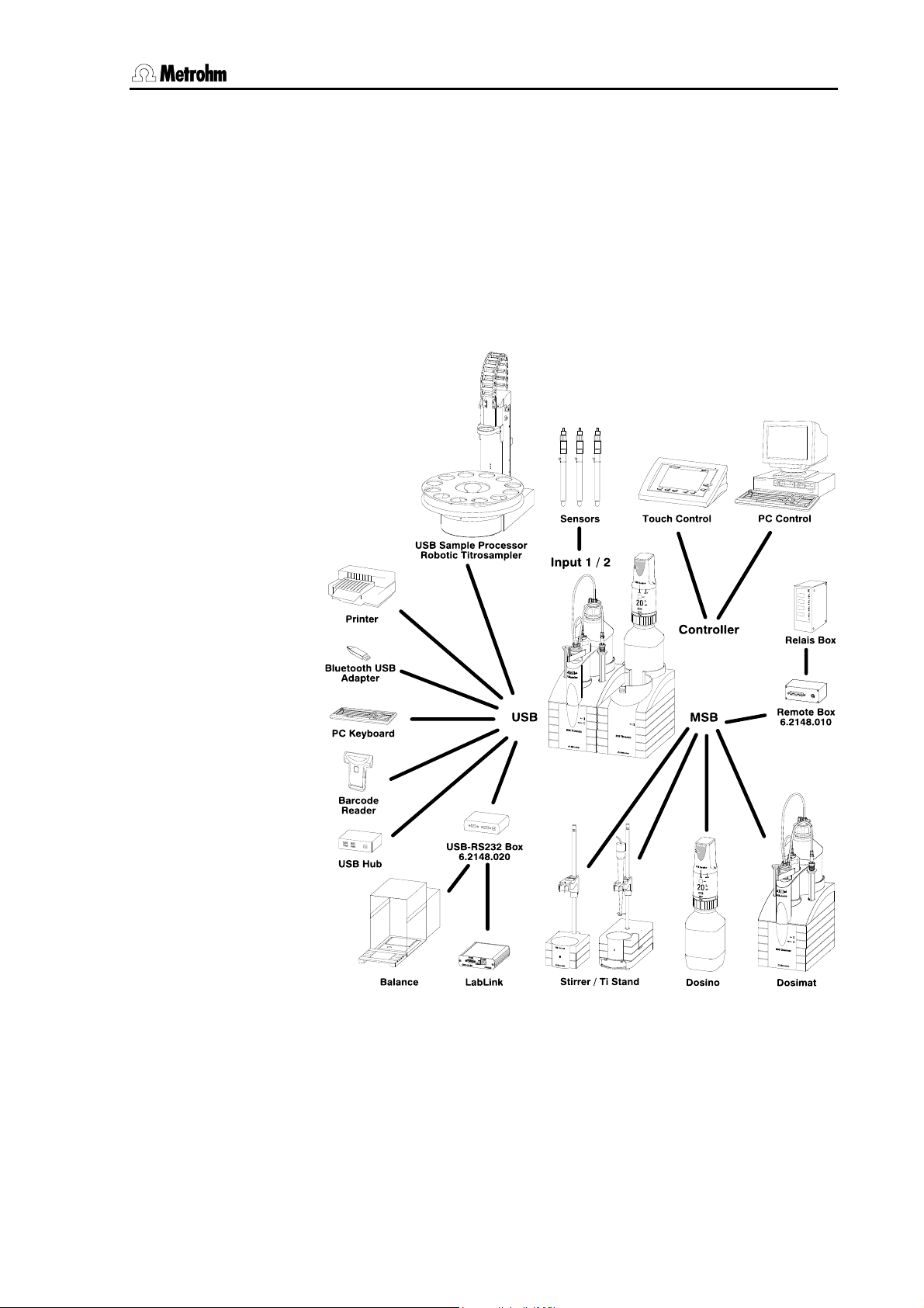
The following illustration provides an overview of the peripheral devices
that can be connected to a Titrando:
Fig. 5: Titrando – Peripheral devices
Titrando Installation Instructions 9
Page 16
2.1 Overview
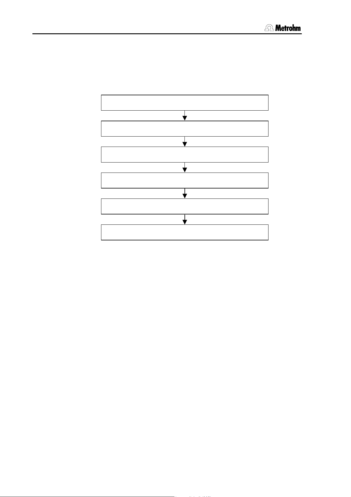
2.1 Overview
The following flow diagram provides an overview of the installation of a
simple titration system with stirrer, external dosing device, printer and
balance. More detailed information can be found in the given sections.
Setup Section 2.2
Touch Control/Computer connection Section 2.3
Stirrer/Titration stand connection Section 2.4.1
Dosing device connection Section 2.4.2 and 2.4.3
Printer connection Section 2.5.1
Balance connection Section 2.5.2
10 Titrando Installation Instructions
Page 17
2 Installation
2.2 Instrument setup
2.2.1 Packaging
The Titrando and the separately packed accessories are delivered in
special packaging that provides excellent protection. Please store this
packaging in a safe place as no other packaging can guarantee the
safe transport of the instrument.
2.2.2 Checks
Please check whether the delivery is complete and undamaged immediately on receipt (compare with delivery note and list of accessories
given in Section 4.2). If transport damage is evident please refer to the
information given in Section 4.4.1.
2.2.3 Location
The Titrando was developed for internal laboratory use; it should not be
used in explosion-endangered locations.
Place the instrument on a suitable vibration-free laboratory bench, protected as much as possible from corrosive atmospheres and contact
with chemicals.
Choose a location where the temperature is usually between +5 °C and
+45 °C. The instrument should be protected against excessive variations in temperature and direct sunlight.
2.3 Controller connection
Two different methods of controlling the Titrando are available:
• The Touch Control with contact-sensitive screen forms a “stand-
alone” titrator together with the Titrando.
• A computer can be used to control the Titrando by using the PC
software PC Control or tiamo.
Attention!
Make sure that the mains cable has been removed from the power
supply socket before setting up or breaking connections between the
instruments.
Titrando Installation Instructions 11
Page 18
2.3 Controller connection
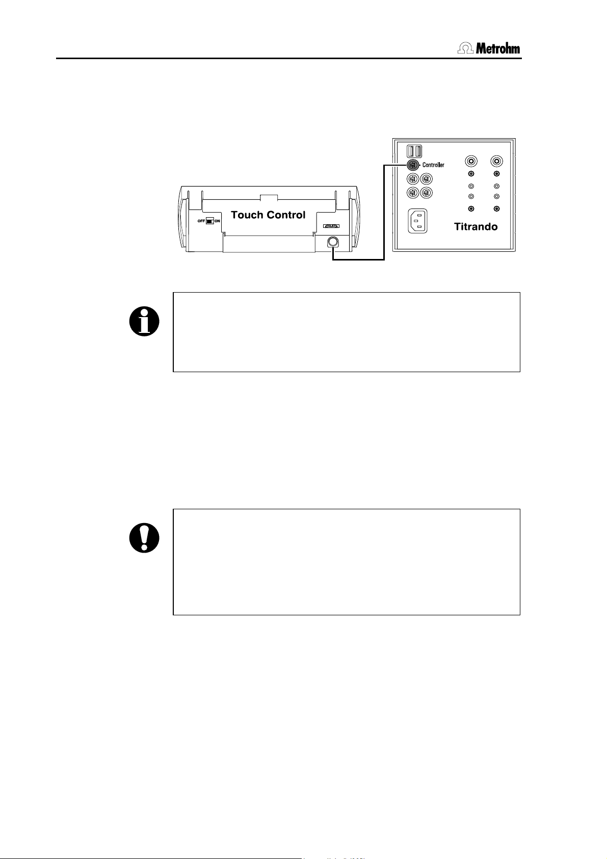
2.3.1 Touch Control connection
Connect the plug of the Touch Control connection cable to the con-
troller socket.
Fig. 6: Titrando – Touch Control
Note!
The plug is fitted with a "pull-out protection device" that prevents the
cable from being pulled out accidentally. When you wish to insert or
remove the plug you must first pull back the outer plug sleeves
(marked with arrows).
Connect all peripheral devices (see Section 2.4 and 2.5) before you
switch on the Touch Control.
Power for the Touch Control is provided by the Titrando.
Connect the Titrando to the mains supply and switch on the Touch
Control.
After switch-on automatic system tests are carried out on both the Titrando and the Touch Control. The "On" LED on the Titrando lights up
when the system test is finished and the instrument is ready for use.
Attention!
The Touch Control has to be shut down properly with the ON/OFF
switch at the back of the instrument before the power supply is interrupted. Otherwise data can be lost. Since the power for the Touch
Control is supplied by the Titrando, never disconnect the Titrando
from the mains connection (e. g. by switching it off via a mains distributor), before you have switched off the Touch Control.
If you do not want to place the Touch Control directly alongside the Titrando then you can extend the connection between the Titrando and
Touch Control with the 6.2151.010 Cable. The connection length must
not exceed 5 m.
12 Titrando Installation Instructions
Page 19
2 Installation
2.3.2 Computer connection
Install the PC Control or tiamo software on your computer. Quit
the program if you have started it after the installation.
Connect all peripheral devices (see Section 2.4 and 2.5) before you
connect the Titrando to the mains supply.
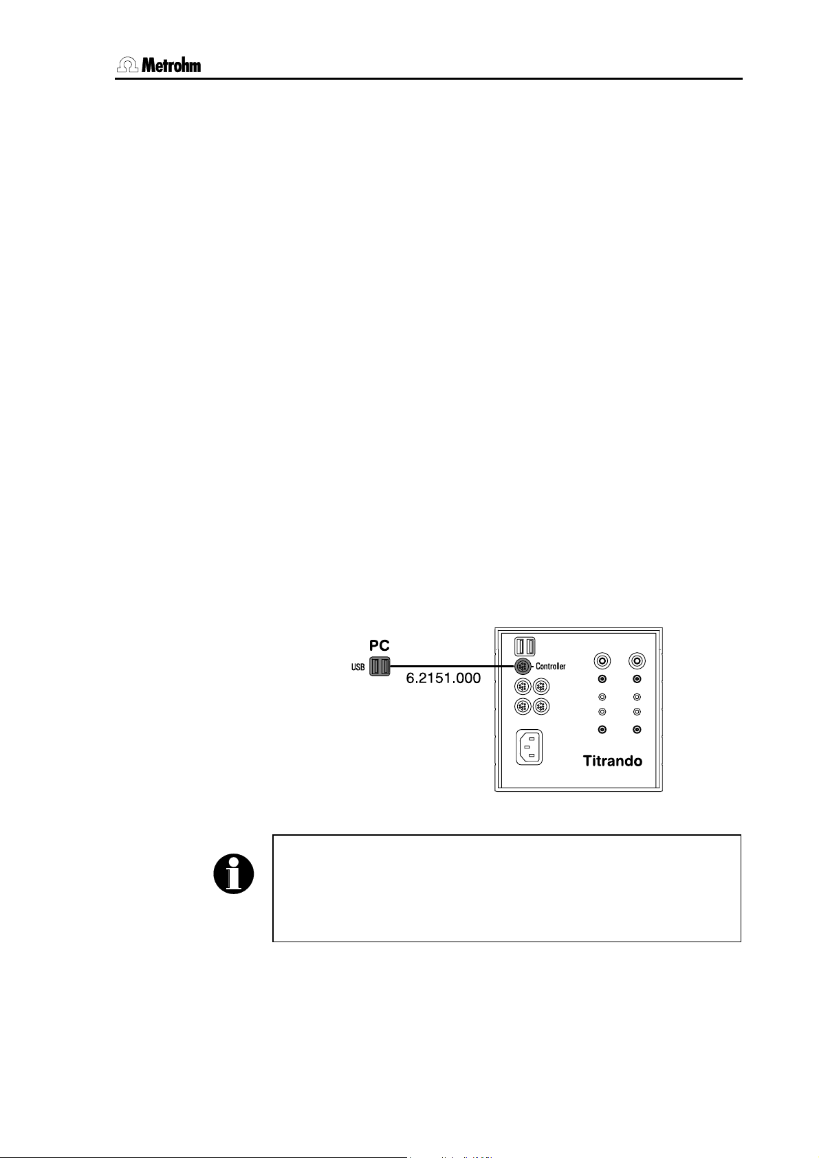
Connect the Titrando to the mains supply. The LED "On" on the Ti-
trando will not yet light up!
Connect the Titrando to a USB connection (type A) on your com-
puter with the 6.2151.000 cable (see the instruction manual for your
computer).
Windows 2000: The Titrando will be recognized and the driver will be
installed automatically. Windows XP: The Titrando will be recognized
and the wizard for the installation of the driver will be started automatically. Select the option "Install the software automatically" and click on
[Next]. End the wizard with [Finish].
PC Control
Connect the USB dongle ("authorization plug") supplied with the full
version of the PC Control software to any USB socket (type A) of the
computer or Titrando.
Windows 2000: The USB dongle will be recognized and the driver will
be installed automatically. Windows XP: The USB dongle will be recognized and the wizard for the installation of the driver will be started
automatically. Select the option "Install the software automatically" and
click on [Next]. End the wizard with [Finish].
Fig. 7: Titrando – Computer
Note!
The plug for connecting to the Titrando is fitted with a "pull-out protection device" that prevents the cable from being pulled out accidentally.
When you wish to insert or remove the plug you must first pull back
the outer plug sleeves (marked with arrows).
You can extend the connection with a commercially available USB extension cable (type A/m – type A/f). The length of the connection should
not exceed 5 m. If you require a longer connection then you must use a
commercially available USB signal amplifier. Up to five USB signal am-
Titrando Installation Instructions 13
Page 20
2.4 Device connection at the MSB
plifiers can be connected in series; this allows a maximum extension of
25 m.
Start the PC Control or tiamo software.
The Titrando will be recognized automatically. When the PC Control or
tiamo software is started a system test will be carried out automatically
on the Titrando. The LED "On" on the Titrando lights up when the system test is finished and the instrument is ready for use.
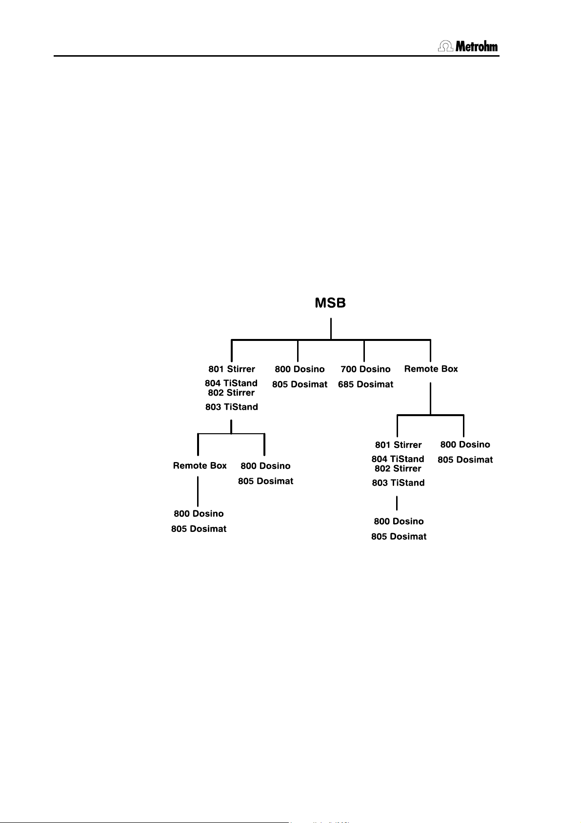
2.4 Device connection at the MSB
The following devices can be connected via each of the four MSB connections (Metrohm Serial Bus): one stirrer or titration stand, one Dosimat or Dosino dosing device and one remote box. The stirrers and
remote boxes each have an MSB output so that the devices can be
switched sequentially ("daisy chain"). The following illustration provides
an overview of the devices that can be connected to an MSB.
Fig. 8: Overview of MSB connections
The MSB 1 of the Titrando with internal dosing drive is occupied by the
internal dosing drive. This means that only a stirrer and a remote box
can be connected to MSB 1.
First connect all peripheral devices and then connect the Titrando to the
mains supply. MSB connections can be extended with the 6.2151.010
cable. The maximum length of the connection is 15 m.
The Titrando automatically recognizes which device has been connected to which MSB connection. The Touch Control or the PC software
(PC Control or tiamo) shows the connected devices in the device manager or the configuration dialog respectively. All devices connected to
the MSB are operated by the Touch Control or PC Control/tiamo.
14 Titrando Installation Instructions
Page 21
2 Installation
Attention!
If you are operating the Titrando with the Touch Control then make
sure that the Touch Control is switched off while you are setting up or
breaking connections between the instruments. If you are operating
the Titrando with the PC software then pull out the plug from the
power supply socket before setting up or breaking MSB connections.
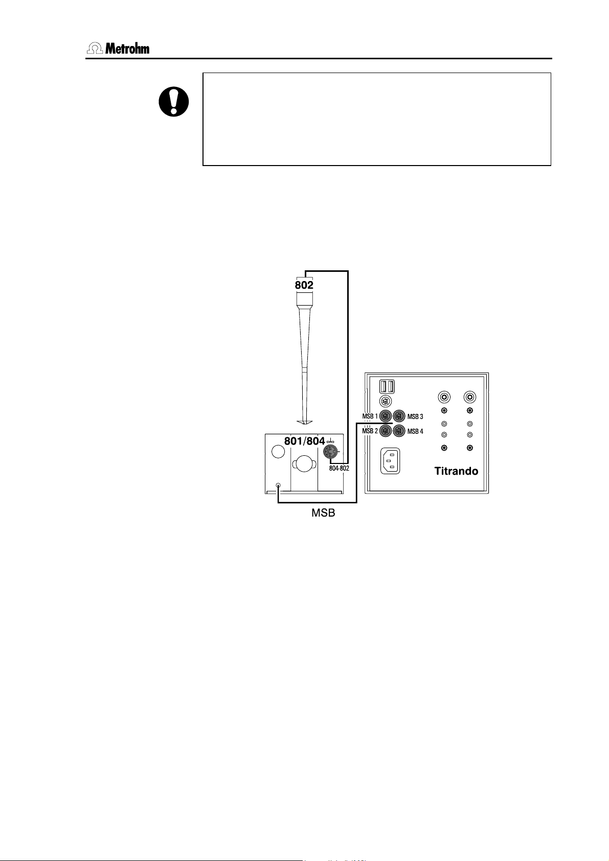
2.4.1 Connecting stirrers and titration stands
You can use the 801 Magnetic Stirrer, the 803 Titration Stand (stirring from below) or the 804 Titration Stand with 802 Rod Stirrer (stirring from above).
Connect the appropriate stirrer as follows:
Fig. 9: Titrando – Stirrer
You can connect a maximum of one 801 Stirrer, one 804 Titration Stand
with 802 Rod Stirrer or one 803 Titration Stand to each MSB socket. The
801 Stirrer as well as the 804 and 803 Titration Stands has a MSB connection to which an additional device, e. g. a dosing device, can be
connected. We recommend that the stirrer is connected to MSB 1, as
this corresponds to the default setting in the methods.
The stand and the stand support are included with the stirrer or titration
stand. Fasten the stand support to the base of the Titrando with the four
screws supplied. Decide whether you want to attach the stirrer to the
right or left of the Titrando. The assembly of the support rod and the
stirrer or titration stand is described in the Instructions for Use of the
801 Stirrer and the 804 Titration Stand or the 803 Titration Stand.
Titrando Installation Instructions 15
Page 22

2.4 Device connection at the MSB
2.4.2 Attaching the exchange unit to the Titrando
Type 806 exchange units have a built-in data chip that allows the storage of data concerning the exchange unit and the reagent. Data is edited in the Touch Control or in the PC Control/tiamo software. The assembly of the exchange unit is described in the Instructions for Use of
the exchange unit.
Fig. 10: Attaching the exchange unit to the Titrando
Slide the exchange unit onto the Titrando so that it snaps into posi-
tion and the "Status" LED slowly blinks.
If the exchange unit has been properly positioned then the exchange
unit guide bolts will operate a microswitch and trigger the exchange unit
initialization. The exchange unit will be recognized and the data is
automatically read out from the data chip. The "Status" LED then lights
up constantly.
The following table provides an overview of the operating statuses of
the internal dosing device that can be indicated by the "Status" LED:
16 Titrando Installation Instructions
Page 23

2 Installation
"Status" LED Dosing device operating status
off There is no exchange unit at-
tached.
constant illumination The Titrando is ready for dosing
or titrating. The exchange unit
has been attached correctly and
recognized and is now in the
change position, i. e. the exchange unit can be removed.
blinks slowly The Titrando is currently dosing
or filling or the exchange unit is
not in the change position.
An intelligent 806 Exchange unit
has been attached and the data
on the built-in data chip is currently being read out or written.
blinks rapidly Dosing drive error (see Sec-
tion 3, Troubleshooting)
Titrando Installation Instructions 17
Page 24

2.4 Device connection at the MSB
2.4.3 Connecting an external dosing device
Three dosing devices of the type 805 or 685 Dosimat or 800 or
700 Dosino can be connected to Titrandos with an internal dosing
drive and four of them to Titrandos without internal dosing drive. MSB 1
is occupied by the built-in dosing drive on the Titrando with internal
dosing drive.
Connect the dosing drive as shown in Fig. 11 and Fig. 12.
Fig. 11: Example for connecting a dosing device:
Titrando – 800 Dosino
18 Titrando Installation Instructions
Page 25

2 Installation
Fig. 12: Example for connecting a dosing device:
Titrando – 805 Dosimat
The 685 Dosimat is connected to the Titrando with the 6.2134.030 cable. 685 Dosimat and 700 Dosino types must be connected directly to
the MSB socket of the Titrando (see Fig. 8: Overview of MSB connections). If you want to connect a stirrer (see Section 2.4.1) and an external 800 Dosino (or 805 Dosimat) dosing device to a Titrando without internal dosing drive then we recommend that the stirrer is connected to
MSB 1 and the dosing device to the MSB connection of the stirrer as
this corresponds to the standard settings in the methods.
Type 806 Exchange units for the 805 Dosimat and type 807 Dosing
units for the 800 Dosino have a built-in data chip that allows the storage
of data about the exchange or dosing unit and the reagent. This data is
automatically read out or updated by Touch Control or PC Control/tiamo when the exchange or dosing unit is attached to the dosing
device. The data is edited in the Touch Control or in the PC Control/tiamo software.
Titrando Installation Instructions 19
Page 26
2.4 Device connection at the MSB
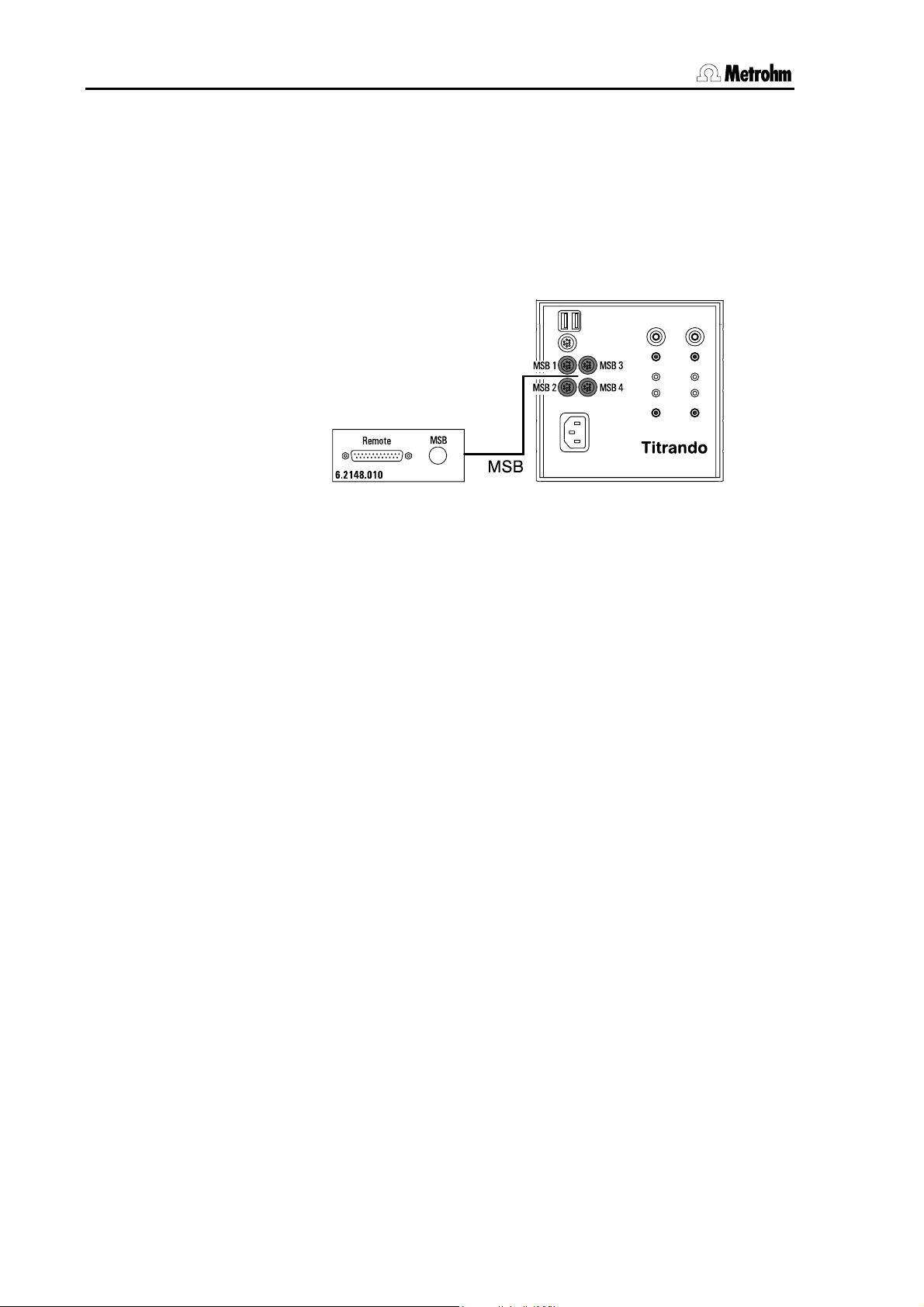
2.4.4 Connecting a remote box
Instruments that are controlled by remote lines or can transmit signals
to the Titrando via remote lines can be connected to the Titrando via the
6.2148.010 Remote box. The pin occupancy of the remote socket is
described in the Instructions for Use for PC Control / Touch Control.
Connect the remote box to an MSB connection on the Titrando in
the following way:
Fig. 13: Titrando – Remote box
For example, you can connect the 849 Level Control to the remote interface of the remote box. The remote box also has an MSB output, to
which an additional instrument, e. g. a dosing device or stirrer, can be
connected.
During a method run remote output lines are set automatically and the
setting of input lines by a peripheral device can automatically trigger
commands (e. g. start or stop). An exact description of the signals is
given in the Instructions for Use for PC Control / Touch Control.
PC Control / Touch Control
If you have several remote boxes connected then you must remember
that the particular remote box that is recognized first by the software
(Touch Control or PC Control) will automatically be used as the "Control
remote box". This means that lines will be set up and scanned automatically on this remote box. The current Control remote box is shown
in the device manager under the Touch Control or PC Control properties (see Instructions for Use for PC Control / Touch Control).
20 Titrando Installation Instructions
Page 27

2 Installation
2.5 Device connection at the USB
The Titrando has two USB connections (type A sockets) for connecting
peripheral devices with a USB interface. The Titrando functions as the
USB hub (distributor), regardless of whether you are using it with Touch
Control or PC Control/tiamo. If you wish to attach more than two devices to a USB then you can also use an additional commercially available USB hub (see Section 2.5.7).
Attention!
If you are operating the Titrando with Touch Control then make sure
that the Touch Control is switched off while you are setting up or
breaking the connections between the instruments. If you are operating the Titrando with the PC software, end the program before setting
up or breaking USB connections.
2.5.1 Connecting a printer
Printers to be connected to the Titrando operated by Touch Control
must meet the following requirements:
• Printer language: HP-PCL, Canon BJL Commands or Epson ESC
P/2
• Printer resolution 300 dpi or 360 dpi (Epson)
• A4 paper, single page feed.
Current printer models that can be connected are listed on the Internet
under www.titrando.com
To connect the printer proceed as follows:
Switch off Touch Control.
Use the 6.2151.020 cable to connect the USB connection of the Ti-
trando (type A) to the USB connection of the printer (type B, see
printer’s operating manual).
.
First switch on the printer and then the Touch Control.
Configure the printer in the device manager of the Touch Control as
described in the Instructions for Use for PC Control / Touch Control.
Fig. 14: Titrando – Printer
Titrando Installation Instructions 21
Page 28

2.5 Device connection at the USB
2.5.2 Connecting a balance
If you are operating the Titrando with the PC Control/tiamo software
then connect the balance directly to the serial interface (COM) of the
computer. This is normally 9-pin and marked with the symbol IOIOI. If
you are operating the Titrando with the Touch Control then you need
the 6.2148.020 USB-RS232 box to connect a balance.
The following table gives an overview of the balances that can be used
together with the Titrando system and which cables you will need to
connect the balance to the RS232 interface:
Balance Cables
AND
6.2125.020 + 6.2125.010
ER-60, 120, 180, 182
FR-200, 300
FX 200, 300, 320
with RS232 interface (OP-03)
Mettler AB, AG, PR (LC-RS9) Supplied with balance
Mettler AM, PM, PE with interface
option 016
or
Mettler AJ, PJ with interface option 018
6.2146.020 + 6.2125.010
additionally from Mettler:
ME 47473 Adapter and either
ME 42500 Hand switch or
ME 46278 Foot switch
Mettler AT 6.2146.020 + 6.2125.010
additionally from Mettler:
ME 42500 Hand switch or
ME 46278 Foot switch
Mettler AX, MX, UMX, PG, AB-S,
6.2134.120
PB-S
Mettler AE with interface option
011 or 012
6.2125.020 + 6.2125.010
additionally from Mettler:
ME 42500 Hand switch or
ME 46278 Foot switch
Ohaus
Cable AS017-09 from Ohaus
Voyager, Explorer, Analytical Plus
Precisa
6.2125.080 + 6.2125.010
balances with RS232C interface
Sartorius MP8, MC1 6.2134.060
Shimadzu BX, BW 6.2125.080 + 6.2125.010
22 Titrando Installation Instructions
Page 29

2 Installation
Operation with Touch Control
Use the 6.2151.030 cable to connect the USB connection of the Ti-
trando (type A) to the USB connection of the USB-RS232 box
(type B).
Connect one of the RS interfaces of the USB-RS232 box with the
RS232 interface of the balance (see Table for cables).
Fig. 15: Titrando – USB-RS232 box – Balance
Switch on the Touch Control.
Switch on the balance.
Configure the RS232 interface of the balance.
Configure the RS232 interface of the USB-RS232 box in the device
manager of the Touch Control (see Instructions for Use for PC Control / Touch Control).
Operation with PC Control/tiamo
Connect the RS232 interface of the computer with the RS232 inter-
face of the balance (see Table for cables).
Switch on the balance.
Configure the RS232 interface of the balance.
Configure the RS232 interface of the computer in the device man-
ager of the PC Control software (see Instructions for Use for PC
Control / Touch Control) or in the configuration dialog of tiamo.
Titrando Installation Instructions 23
Page 30
2.5 Device connection at the USB
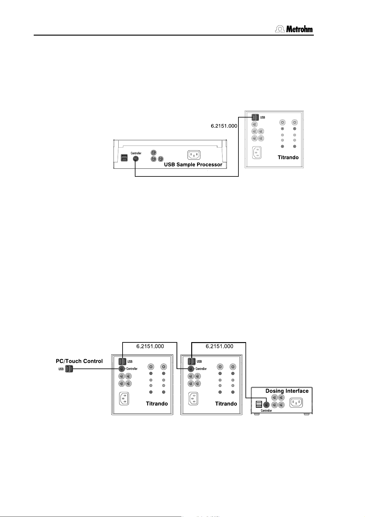
2.5.3 Connecting a USB Sample Processor / Robotic Titrosampler
A USB Sample Processor or a Robotic Titrosampler can be controlled
by Touch Control or PC Control/tiamo.
Use the 6.2151.000 cable to connect the USB connection of the Ti-
trando (type A) with the controller socket of the USB Sample Processors / Robotic Titrosampler.
Fig. 16: Titrando –USB Sample Processor
Start the PC Control/tiamo software or switch on the Touch Control.
The USB Sample Processor / Robotic Titrosampler will be recognized automatically and entered in the device list of PC Control/tiamo or Touch Control.
Configure the USB Sample Processor / Robotic Titrosampler in the
device manager or the configuration dialog as described in the Instructions for Use for PC Control / Touch Control or tiamo respectively.
2.5.4 Connecting additional Titrandos or Dosing Interfaces
With the Touch Control or the PC Control software you can control up to
three Titrandos or Dosing Interfaces. The tiamo software allows to expand the system with practically any number of control devices.
Use the 6.2151.000 cable to connect the USB connection of the first
Titrando / Dosing Interface (type A) with the controller socket of the
second Titrando / Dosing Interface.
Fig. 17: Titrando – Titrando/Dosing Interface
Switch on the Touch Control or start the PC Control/tiamo software.
The Titrando / Dosing Interface will be recognized automatically and
entered in the device list of PC Control/tiamo or Touch Control.
24 Titrando Installation Instructions
Page 31

2 Installation
Configure the Titrando / Dosing Interface in the device manager or
the configuration dialog as described in the Instructions for Use for
PC Control / Touch Control or tiamo respectively.
You can connect another Titrando or Dosing Interface in the manner
described above.
Attention!
Connecting Titrandos/Dosing Interfaces via a commercially available
USB hub is not possible.
2.5.5 Connecting a PC keyboard (Titrando with Touch Control only)
The PC keyboard is used as an aid for entering text and numbers. If you
are operating the Titrando with the Touch Control then you can connect
a PC keyboard with USB interface to the Titrando. Current keyboard
models that can be connected are listed on the Internet under
www.titrando.com
Connect the USB plug of the keyboard (type A) to one of the USB
sockets of the Titrando.
Switch on the Touch Control. The keyboard will be automatically
recognized and entered in the device manager.
Configure the keyboard in the device manager of the Touch Control
as described in the Instructions for Use for PC Control / Touch Control.
.
2.5.6 Connecting a barcode reader
The barcode reader is used as an aid for entering text and numbers.
You can connect a barcode reader with USB-interface. Current barcode
reader models that can be connected are listed on the Internet under
www.titrando.com
Operation with Touch Control
Connect the USB plug of the barcode reader (type A) to one of the
USB sockets of the Titrando.
Switch on the Touch Control. The barcode reader will be automati-
cally recognized and entered in the device manager of the Touch
Control.
Configure the barcode reader in the device manager as described
in the Instructions for Use for PC Control / Touch Control.
Operation with PC Control/tiamo
Connect the USB plug of the barcode reader (type A) to one of the
USB sockets of the Titrando or the computer.
Start the PC Control or tiamo software.
Configure the barcode reader in the device manager or the configu-
ration dialog as described in the Instructions for Use for PC Control / Touch Control or tiamo respectively.
.
Titrando Installation Instructions 25
Page 32

2.5 Device connection at the USB
Settings on the barcode reader:
The operating instructions of the barcode reader describe the programming of the barcode reader.
Bring the barcode reader into the programming mode.
Set the required keyboard layout (USA, Germany, France, Spain,
Switzerland (German)). This setting must be the same as the setting
in the device manager (see Instructions for Use for PC Control / Touch Control).
Make sure that the barcode reader is set so that Ctrl-characters
(ASCII 00 to 31) can be transmitted.
Program the barcode reader so that ASCII character 02 (STX or
Ctrl B) is the first character to be transmitted. This first character is
normally known as the "Preamble" or "Prefix code".
Program the barcode reader so that ASCII character 04 (EOT or
Ctrl D) is the last character to be transmitted. This last character is
normally known as the "Postamble", "Record suffix" or "Postfix code".
Terminate the programming mode.
2.5.7 Connecting a USB hub
If you would like to connect more than two devices to the USB connection of the Titrando then you can use an additional commercially available USB hub (distributor). If you are operating the Titrando with the
Touch Control then you should use a self-powered USB hub.
Switch off the Touch Control or close the PC Control/tiamo software.
Use the 6.2151.020 cable to connect the USB connection of the Ti-
trando (type A) with the USB connection of the hub (type B, see operating instructions of hub).
Switch on the Touch Control or start the PC Control/tiamo software.
The USB hub will be recognized automatically.
2.5.8 Connecting a Bluetooth® adapter
Printers and balances (or other instruments with RS232 connection) can
be connected optionally via a wireless Bluetooth
of printers and balances with integrated Bluetooth
ommended for this. Bluetooth
Bluetooth
are commercially available.
Note!
Bluetooth
Special Interest Group (Bluetooth
®
serial adapters for RS232 connections (e. g. for balances)
®
is a registered and protected trademark of the Bluetooth®
®
®
connection. Models
®
functionality are rec-
printer adapters for the USB port and
®
SIG, Inc.).
26 Titrando Installation Instructions
Page 33

2 Installation
PC Control and tiamo
If the Titrando system is operated with the PC Control/tiamo software, a
Bluetooth USB adapter can be connected to a USB port of the computer (or of the Titrando/USB Sample Processor). The driver software
(for MS Windows 2000/XP), supplied by the manufacturer of the Bluetooth adapter, must be installed as specified in the related instructions.
A Bluetooth USB adapter must support the Bluetooth specifications
HCRP (Hardcopy Cable Replacement Profile for printers) and/or
SPP (Serial Port Profile for balances or RS232 connections). Printer
drivers must be configured before installation of the Bluetooth adapter.
Touch Control
If the Titrando system is operated as a stand-alone system with an
840 Touch Control, the Metrohm Bluetooth USB Adapter for 840
(6.2162.000, Bluetooth
for a Bluetooth connection.
®
V1.1 qualified Class 2 device) will be required
Note!
The Metrohm Bluetooth USB Adapter cannot be operated on a
computer. The adapter is designed exclusively for use in a Titrando
system in stand-alone mode, i. e. with a 840 Touch Control as control
unit. The version 5.840.0130 or higher of the Touch Control software is
required.
The Metrohm Bluetooth USB adapter guarantees wireless data transfer
over a distance of up to 10 m and is easy to install.
Connect the Bluetooth adapter to a free USB port on the rear of the
Titrando/USB Sample Processor.
Switch on the Touch Control. The Bluetooth USB adapter is recog-
nized automatically.
Configure the adapter in the device manager of the Touch Control
as described in the Instructions for Use for PC Control/Touch Control.
Printers and Bluetooth
A Bluetooth-enabled printer or a Bluetooth printer adapter must support
the HCRP Hardcopy Cable Replacement Profile.
Please refer to the printer's User Manual for the settings required for a
Bluetooth-enabled printer. Bluetooth printer adapters can normally be
connected to the USB port of the relevant printer without the need for
configuration. Please note what is said in the printer adapter's documentation. The printer type is defined in the device manager of Touch
Control.
Balances and Bluetooth
A Bluetooth-enabled balance or a Bluetooth serial adapter must comply
with the SPP Serial Port Profile in accordance with the Bluetooth
specifications. If the manufacturer of the balance offers a specific Blue-
Titrando Installation Instructions 27
Page 34

2.5 Device connection at the USB
tooth serial adapter, this should be used instead of a commercially
available adapter.
Bluetooth serial adapters must be configured on the PC using the utility
program supplied by the manufacturer. The data transfer parameters of
instrument and adapter must agree with each other. The Bluetooth serial adapter must be defined as Acceptor and not as Initiator of a serial
connection. Authentication with a PIN code is not supported.
28 Titrando Installation Instructions
Page 35

2 Installation
2.6 Sensor connection
One measuring interface consists of a high-impedance measuring input
(Ind.) for pH, redox or ISE sensors, an input for a separate reference
electrode (Ref.), a measuring input for temperature sensors (Temp.),
e. g. Pt1000 or NTC and a measuring input for polarized electrodes
(Pol.).
Fig. 18: Titrando – Sensors
2.6.1 Connecting an 854 iConnect
One or two external 854 iConnect measuring interfaces can be connected to an 857 Titrando depending on the Titrando's version.
Connect the iConnect plug of the 854 iConnect to the socket "iCon-
nect" of the 857 Titrando. Make sure that the mark on the plug
points to the mark on the Titrando as shown in the figure.
Fig. 19: Connecting the 854 iConnect
The 854 iConnect is recognized automatically and entered as
measuring input in the device properties of the Titrando.
The connection of sensors is described in the Instructions for Use of the
854 iConnect.
Titrando Installation Instructions 29
Page 36

2.6 Sensor connection
2.6.2 Differential potentiometry
During potentiometric measurements in poorly conducting media, highimpedance measuring sensors are affected by electrostatic and electromagnetic interferences. Use our Solvotrode 6.0229.100 or any other
special electrode for pH measurements in organic solvents. If this does
not help then you can connect a Differential amplifier 6.5104.030
(230 V) or 6.5104.040 (115 V).
The Differential amplifier is connected to the high-impedance measuring input (Ind.).
2.6.3 Titration vessel setup
In titration it is important that the solution is thoroughly mixed. The stirring rate should be high enough for a small vortex to be formed. If the
stirring rate is too high then air bubbles will be entrained. This results in
incorrect measurements. If the stirring rate is too low then the solution
at the electrode will not be correctly mixed. To ensure that the measurement is made in a thoroughly mixed solution after titrant addition the
buret tip should be located where the turbulence is greatest. In addition, the distance between the spot where the titrant is added and the
electrode should be as large as possible. When positioning the electrode and buret tip you must also take the stirring direction into account.
1
2
3
Fig. 20: Recommended arrangement of magnetic stirring bar (1),
electrode (2) and buret tip (3)
30 Titrando Installation Instructions
Page 37

2 Installation
2.6.4 Assembly of the Karl Fischer titration cell
Install the titration cell for volumetric KF titrations according to the following figures:
Fig. 21: Drawing of the KF titration cell 6.5609.000
Titrando Installation Instructions 31
Page 38

2.7 Update of the instrument software
Fig. 22: Arrangement of transport tip, buret tip and draw-off tip
1 Position of the transport tip for sol-
vent
2 Position of the buret tip for KF re-
agent
3 Position of the draw-off tip
2.7 Update of the instrument software
The Update of the instrument software is described in the Instructions
for Use for PC Control / Touch Control or in the tiamo help.
32 Titrando Installation Instructions
Page 39

3 Troubleshooting
3 Troubleshooting
3.1 Problems
Problem Possible cause Measures
"On" LED does not
light up although the
Titrando is connected to the mains
supply.
Titrando with internal
dosing drive only:
"Status" LED does
not light up although
an exchange unit is
in place.
Titrando with internal
dosing drive only:
The exchange unit
cannot be pushed
into position.
Either the Touch Control or
the computer is not switched
on, or the plugs are not
plugged in correctly.
The exchange unit has not
been attached correctly.
The exchange unit flat cock
is not in the change position.
The piston rod in the exchange unit is not in the correct position.
Check the plug connections and
switch on the Touch Control or the
computer.
Remove the exchange unit and
push it on again until it clicks into
position. The LED blinks while the
data is being read out from an intelligent exchange unit (806) and is on
continuously when the exchange
unit has been recognized correctly.
Move the flat cock manually to the
change position (switch lever pointing to the right).
Move the piston rod to the correct
position (see exchange unit Instructions for Use, Section "Attaching
the exchange unit").
Titrando with internal
dosing drive only:
The exchange unit
cannot be removed
and the "Status" LED
blinks slowly.
Dosing or filling is currently
taking place and / or the Titrando is not in the change
position.
Stop the run or carry out a "Fill"
step.
Titrando Installation Instructions 33
Page 40

3.1 Problems
Problem Possible cause Measures
Titrando with internal
dosing drive only:
"Status" LED blinks
rapidly.
The dosing drive is overloaded because the flat cock
is blocked.
The dosing drive is overloaded because the piston is
blocked. The fault is indicated by the software (Touch
Control or PC Control/tiamo).
Switch off the Touch Control or end
PC Control/tiamo. Check whether
the exchange unit can be removed.
If it cannot be removed then check
whether the flat cock can still be
rotated. Move it manually to the
change position by turning it to the
right (see Instructions for Use of
exchange unit). Remove the exchange unit and proceed as described in the Instructions for Use
in the section "Servicing a blocked
flat cock".
Switch the control device off and
then on again. The dosing device is
initialized when switching on. Remove the exchange unit and clean
it as described in the Instructions
for Use in the section "Care and
maintenance". Contact Metrohm
Service if it is not possible to remove the exchange unit.
The exchange unit data can
no longer be read as the
data chip has been damaged mechanically or by
chemicals.
Have the data chip replaced by
Metrohm Service personnel.
In order to be able to use the exchange unit until the data chip is
replaced you can remove the data
chip yourself. The cylinder volume
will still be recognized automatically, but data can no longer be
read from or stored in the exchange unit.
34 Titrando Installation Instructions
Page 41

4 Appendix
4 Appendix
In this section you will find the most important technical data of the Titrando, a list of standard and optional accessories and the warranty
and conformity declarations.
4.1 Technical data
Provided that nothing to the contrary is mentioned, the published values are typical technical data for the Titrandos with internal and external
dosing drive.
4.1.1 Titration and measuring modes
DET Dynamic equivalence point titration
Controlled titrant addition with variable volume increments
MET Monotonic equivalence point titration
Titrant addition with fixed volume increments
SET Titration to one or two predefined endpoints
KFT Karl Fischer titration
STAT Endpoint titration while holding the measured value constant
MEAS Measurement (pH, potential, temperature, current (Upol), poten-
tial(Ipol) and concentration)
4.1.2 Measuring interfaces
1 or 2 galvanically separated measuring interfaces
Potentiometry
1 high-impedance measuring input for pH, redox and ISE electrodes
1 reference input for separate reference electrode
Input resistance
Offset current
Temperature
1 measuring input for temperature sensors (Pt1000 or NTC)
Automatic temperature compensation, for NTC sensors R (25 °C) and B
configured.
> 1 * 10
< 1 * 10
(under reference conditions)
12
Ohm
–12
A
25/50
can be
Polarizer
1 measuring input for polarized electrodes
Polarization current Ipol
Polarization potential Upol
Titrando Installation Instructions 35
–125.0 ... +125.0 µA in 2.5 µA steps
–1250 ... +1250 mV in 25 mV steps
Page 42

4.1 Technical data
Polarizer (857 only)
1 measuring input for polarized electrodes
Polarization current Ipol
Polarization potential Upol
1)
–125.0 / +125.0 µA: values not guaranteed, dependent on reference potential
1)
–122.5 ... +122.5 µA in 2.5 µA steps
2)
–1225 ... +1225 mV in 25 mV steps
+2.5 V
2)
–1250 / +1250 mV: values not guaranteed, dependent on reference potential
+2.5 V
4.1.3 Specification of the measuring inputs
Measuring range Resolution Measuring accuracy 1)
pH –20.000 ... +20.000 0.001 pH ± pH 0.003
Potential 2) –2000 mV ... +2000 mV 0.1 mV ± 0.2 mV
Current 3) –200 µA ... +200 µA 0.01 µA −
Temperature
Pt1000
NTC
1)
± 1 digit, without sensor error, under reference conditions
2)
potentiometric and voltametric
3)
amperometric
4)
for a NTC-Sensor with R (25 °C) = 30'000 Ohm and B (25/50) = 4100 K.
–150 °C ... +250 °C
–20 °C ... +250 °C
0.1 °C
4)
0.1 °C
± 0.2 °C (Pt1000: –20 °C ...
+150 °C)
Measuring cycle: 100 ms for all measuring ranges
4.1.4 Specification of the measuring inputs (857 only)
Measuring range Resolution Measuring accuracy 1)
pH –13.000 ... +20.000 0.001 pH ± pH 0.003
Potential 2) –1200 mV ... +1200 mV 0.1 mV ± 0.2 mV
Current 3) –120 µA ... +120 µA 0.01 µA −
Temperature
Pt1000
NTC
–150 °C ... +250 °C
–5 °C ... +250 °C
4)
0.1 °C
0.1 °C
± 0.2 °C (–20 °C... +150 °C)
± 0.6 °C (+10 °C... +40 °C)
1)
± 1 digit, without sensor error, under reference conditions
2)
potentiometric and voltametric
3)
amperometric
4)
for a NTC-Sensor with R (25 °C) = 30'000 Ohm and B (25/50) = 4100 K.
Measuring cycle: 100 ms for all measuring ranges
36 Titrando Installation Instructions
Page 43

4 Appendix
4.1.5 Internal dosing device
Cylinder volume
Exchange unit resolution
Accuracy
4.1.6 Interfaces
USB connections
USB ports 2 USB downstream ports (type A sockets), 500 mA
Controller connection
Controller port USB upstream port with additional signals (mini DIN
Touch Control connection With built-in Touch Control cable
Computer connection With 6.2151.000 cable
MSB connections (MSB = Metrohm Serial Bus)
1 mL, 5 mL, 10 mL, 20 mL or 50 mL
20'000 steps per cylinder volume
0.025% (typical)
Complies with ISO/DIN Standard 8655-3
each, for connection of peripheral devices such as
printer, keyboard, barcode reader or USB-RS232 box
(Metrohm Ordering no. 6.2148.020)
socket) for the connection of Touch Control or computer to control the Titrando.
Dosing device Connection of max. 3 external dosing devices of the
Stirrer Connection of max. 4 stirrers
Remote box Connection of max. 4 remote boxes
4.1.7 Mains connection
Voltage
Frequency
Power consumption
Fuses
type Dosimat or Dosino to Titrandos with internal dosing drive (MSB 2 to MSB 4) or 4 external dosing devices of the type Dosimat or Dosino to Titrandos without internal dosing drive (MSB 1 to MSB 4).
Stirrer control: on/off; manual or coordinated with the
titration procedure.
15 steps for speed and direction of rotation selectable.
Remote boxes are used to select and control external
devices.
100 ... 240 V (± 10%)
50 ... 60 Hz
45 W
electronic overload protection
Titrando Installation Instructions 37
Page 44

4.1 Technical data
4.1.8 Safety specifications
Construction and testing According to EN/IEC/UL 61010-1, CSA-C22.2 No.
61010-1 protection class I
Safety information The Installation Instructions contain safety information
that must be observed by the user in order to ensure
the safe operation of the instrument.
4.1.9 Electromagnetic compatibility (EMC)
Emission Standards complied with:
- EN/IEC 61326
- EN 55022 / CISPR 22
Immunity Standards complied with:
- EN/IEC 61326
- EN/IEC 61000-4-2
- EN/IEC 61000-4-3
- EN/IEC 61000-4-4
- EN/IEC 61000-4-5
- EN/IEC 61000-4-6
- EN/IEC 61000-4-11
4.1.10 Ambient temperature
Nominal working range
Automatic inside temperature monitoring
Storage
Transport
+5 °C ... +45 °C (at max. 85 % rel. humidity)
> 70 °C pre-alarm, > 75 °C alarm
–20 °C ... +60 °C
–40 °C ... +60 °C
4.1.11 Reference conditions
Ambient temperature
Rel. humidity
Warmed-up condition
Validity of data
+25 °C (±3 °C)
≤ 60 %
Instrument in operation for at least 30 min
After adjustment
38 Titrando Installation Instructions
Page 45
4 Appendix
4.1.12 Dimensions
Titrando with internal dosing drive
Housing material Polybutylene terephthalate (PBT)
Width
Height (without exch. unit)
Height (with exch. unit)
Depth
Weight (without exch. unit) 2948 g
Titrando without internal dosing drive
Housing material Polybutylene terephthalate (PBT)
Width
Height
Depth
Weight 2817 g
142 mm
164 mm
approx. 450 mm
239 mm
142 mm
227 mm
231 mm
4.1.13 Recycling and disposal
This product is covered by European Directive 2002/96/EC, WEEE – Waste
from Electrical and Electronic Equipment.
The correct disposal of your old equipment will help to prevent negative
effects on the environment and public health.
More details about the disposal of your old equipment can be obtained
from your local authorities, from waste disposal companies or from your
local dealer.
Titrando Installation Instructions 39
Page 46
4.2 Standard equipment
4.2 Standard equipment
Immediately upon receipt of the Titrando please check that the delivery
is complete. The illustrations in the accessory lists are not to the same
scale.
4.2.1 808 Titrando
The 808 Titrando is available in the 2 following versions:
• 2.808.0010 808 Titrando with one measuring interface
• 2.808.0020 808 Titrando with two galvanically separated
measuring interfaces
The information given in brackets refers to 2.808.0020.
No. Order No. Description
1 1.808.0010
or
1.808.0020
1 6.0262.100 Ecotrode Plus
1 6.2104.020 Connection cable for Metrohm electrodes with plug head
1 6.2739.010 Key for exchange units
1 (2)
1 (2)
1
6.2103.130
6.2103.140
6.2122.020
6.2122.040
6.2122.070
808 Titrando with one measuring interface
or
808 Titrando with two galvanically separated measuring interfaces
Combined LL pH glass electrode with fixed ground-joint diaphragm
length 1 m
Adapter red
Adapter black
for temperature sensor
2 mm plug / 4 mm socket
Mains cable (plug to customer’s specification)
Type SEV 12 (Switzerland)
Type CEE(7), VII (Germany,...)
Type NEMA/ASA (USA,...)
1 8.840.1133 Installation Instructions for Titrando
40 Titrando Installation Instructions
Page 47

4 Appendix
4.2.2 809 Titrando
The 809 Titrando is available in the 2 following versions:
• 2.809.0010 809 Titrando with one measuring interface
• 2.809.0020 809 Titrando with two galvanically separated
measuring interfaces
The information given in brackets refers to 2.809.0020.
No. Order no. Description
1 1.809.0010
or
1.809.0020
809 Titrando with one measuring interface
or
809 Titrando with two galvanically separated measuring interfaces
1 6.0262.100 Ecotrode Plus
Combined LL pH glass electrode with fixed ground-joint diaphragm
1 6.2104.020 Connection cable for Metrohm electrodes with plug head
length 1 m
2 6.2043.005 Holding clip for bottle
1 (2)
1 (2)
6.2103.130
6.2103.140
Adapter red
Adapter black
for temperature sensor
2 mm plug / 4 mm socket
1
6.2122.020
6.2122.040
6.2122.070
Mains cable (plug to customer’s specification)
Type SEV 12 (Switzerland)
Type CEE(7), VII (Germany,...)
Type NEMA/ASA (USA,...)
1 8.840.1133 Installation Instructions for Titrando
Titrando Installation Instructions 41
Page 48

4.2 Standard equipment
4.2.3 835 Titrando
The 835 Titrando is available in the 2 following versions:
• 2.835.0010 835 Titrando with one measuring interface
• 2.835.0020 835 Titrando with two galvanically separated
measuring interfaces
The information given in brackets refers to 2.835.0020.
No. Order No. Description
1 1.835.0010
or
1.835.0020
835 Titrando with one measuring interface
or
835 Titrando with two galvanically separated measuring interfaces
1 6.0262.100 Ecotrode Plus
Combined LL pH glass electrode with fixed ground-joint diaphragm
1 6.2104.020 Connection cable for Metrohm electrodes with plug head
length 1 m
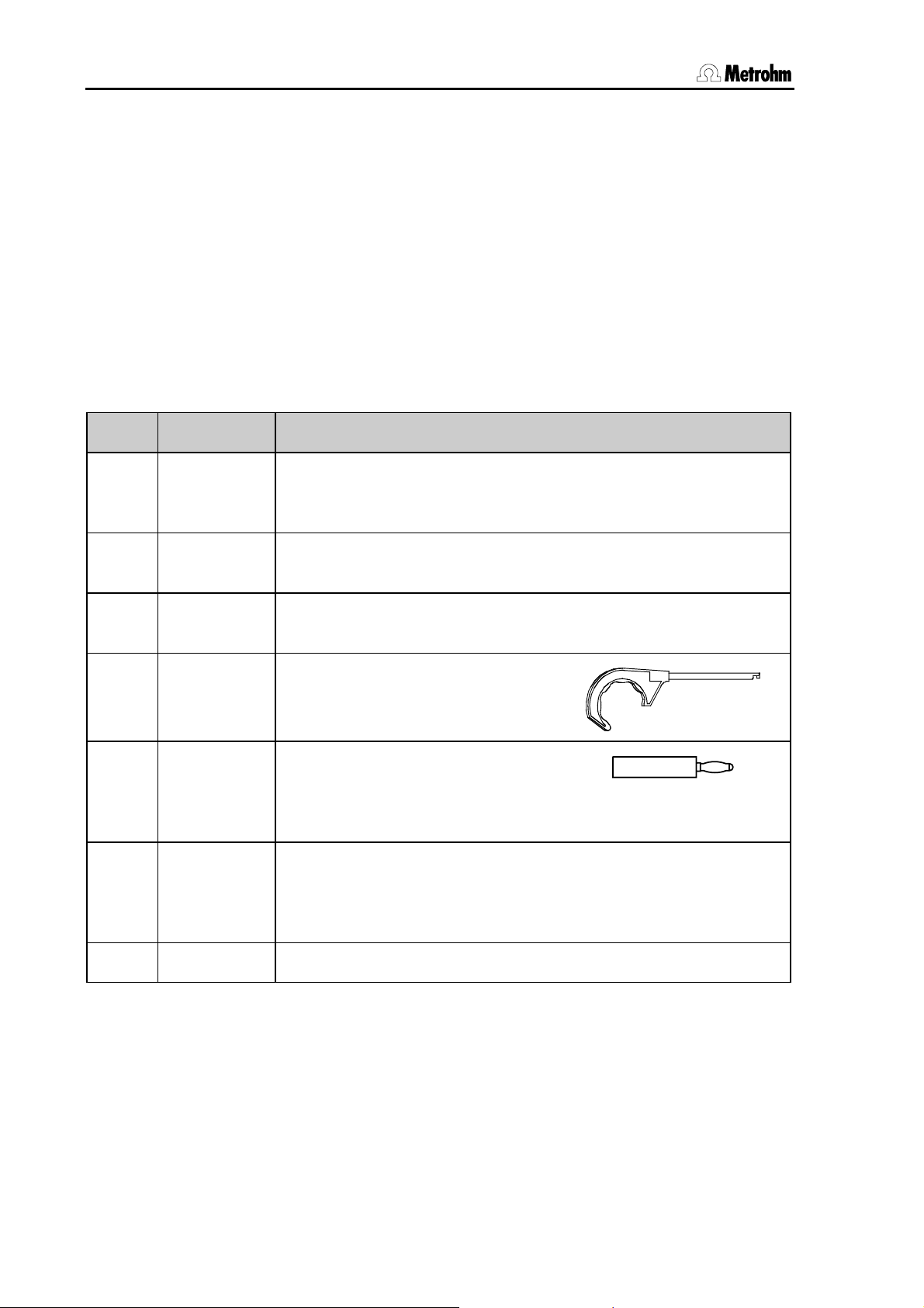
1 6.2739.010 Key for exchange units
1 (2)
1 (2)
6.2103.130
6.2103.140
Adapter red
Adapter black
for temperature sensor
2 mm plug / 4 mm socket
1
6.2122.020
6.2122.040
6.2122.070
Mains cable (plug to customer’s specification)
Type SEV 12 (Switzerland)
Type CEE(7), VII (Germany,...)
Type NEMA/ASA (USA,...)
1 8.840.1133 Installation Instructions for Titrando
42 Titrando Installation Instructions
Page 49

4 Appendix
4.2.4 836 Titrando
The 836 Titrando is available in the 2 following versions:
• 2.836.0010 836 Titrando with one measuring interface
• 2.836.0020 836 Titrando with two galvanically separated
measuring interfaces
The information given in brackets refers to 2.836.0020.
No. Order no. Description
1 1.836.0010
or
1.836.0020
836 Titrando with one measuring interface
or
836 Titrando with two galvanically separated measuring interfaces
1 6.0262.100 Ecotrode Plus
Combined LL pH glass electrode with fixed ground-joint diaphragm
1 6.2104.020 Connection cable for Metrohm electrodes with plug head
length 1 m
2 6.2043.005 Holding clip for bottle
1 (2)
1 (2)
6.2103.130
6.2103.140
Adapter red
Adapter black
for temperature sensor
2 mm plug / 4 mm socket
1
6.2122.020
6.2122.040
6.2122.070
Mains cable (plug to customer’s specification)
Type SEV 12 (Switzerland)
Type CEE(7), VII (Germany,...)
Type NEMA/ASA (USA,...)
1 8.840.1133 Installation Instructions for Titrando
Titrando Installation Instructions 43
Page 50

4.2 Standard equipment
4.2.5 841 Titrando
The 841 Titrando is available in the following version:
• 2.841.0010 841 Titrando with one measuring interface
No. Order no. Description
1 1.841.0010 841 Titrando with one measuring interface
1 6.5609.000 Karl Fischer titration equipment (see Section 4.3.4 and Fig. 21)
2 6.2043.005 Holding clip for bottle
1
1
6.2103.130
6.2103.140
Adapter red
Adapter black
for temperature sensor
2 mm plug / 4 mm socket
1
6.2122.020
6.2122.040
6.2122.070
Mains cable (plug to customer’s specification)
Type SEV 12 (Switzerland)
Type CEE(7), VII (Germany,...)
Type NEMA/ASA (USA,...)
1 8.840.1133 Installation Instructions for Titrando
44 Titrando Installation Instructions
Page 51

4 Appendix
4.2.6 842 Titrando
The 842 Titrando is available in the following version:
• 2.842.0010 842 Titrando with one measuring interface
No. Order no. Description
1 1.842.0010 842 Titrando with one measuring interface
1 6.0262.100 Ecotrode Plus
Combined LL pH glass electrode with fixed ground-joint diaphragm
1 6.2104.020 Connection cable for Metrohm electrodes with plug head
length 1 m
2 6.2043.005 Holding clip for bottle
1
1
6.2103.130
6.2103.140
Adapter red
Adapter black
for temperature sensor
2 mm plug / 4 mm socket
1
6.2122.020
6.2122.040
6.2122.070
Mains cable (plug to customer’s specification)
Type SEV 12 (Switzerland)
Type CEE(7), VII (Germany,...)
Type NEMA/ASA (USA,...)
1 8.840.1133 Installation Instructions for Titrando
Titrando Installation Instructions 45
Page 52

4.2 Standard equipment
4.2.7 857 Titrando
The 857 Titrando is available in the 2 following versions:
• 2.857.0010 857 Titrando with one measuring interface for 854
iConnect
• 2.857.0020 857 Titrando with two galvanically separated
measuring interfaces (one for 854 iConnect, one for
854 iConnect and conventional sensors)
The information given in brackets refers to 2.857.0020.
No. Order no. Description
1 1.857.0010
or
1.857.0020
857 Titrando with one measuring interface
or
857 Titrando with two galvanically separated measuring interfaces
1 1.854.0010 854 iConnect
measuring input
2 6.2043.005 Holding clip for bottle
1
1
6.2103.130
6.2103.140
for 2.857.0020 only:
Adapter red
Adapter black
for temperature sensor
2 mm plug / 4 mm socket
1
6.2122.020
6.2122.040
6.2122.070
Mains cable (plug to customer’s specification)
Type SEV 12 (Switzerland)
Type CEE(7), VII (Germany,...)
Type NEMA/ASA (USA,...)
1 8.840.1133 Installation Instructions for Titrando
46 Titrando Installation Instructions
Page 53

4 Appendix
4.3 Additional instruments and optional accessories
4.3.1 Controller for operating the Titrando
Order no. Description
2.840.0100 Touch Control
with touch-sensitive screen
6.6050.310 PC Control Software 4.1 for Titrando
4.3.2 Stirrers and titration stands
Order no. Description
2.801.0040 801 Magnetic stirrer
with stand and electrode holder for mounting on Titrando
2.801.0010 801 Magnetic stirrer
without stand
2.804.0040 804 Titration stand
for 802 Rod stirrer, with stand and electrode holder for mounting on Titrando
2.804.0010 804 Titration stand
for 802 Rod stirrer, without stand
2.802.0040 802 Rod stirrer for 804 Titration stand
6.1909.010 Propeller stirrer, polypropylene
(length from lower edge of SGJ: 96 mm)
2.803.0010 803 Titration stand
with magnetic stirrer and pump
4.3.3 Titration equipment
Order no. Description
6.5609.000 Karl Fischer titration equipment (see Fig. 21)
6.5613.000 Eco titration equipment
6.1414.010 Titration vessel upper part
for titration vessels 6.1415.xxx and
6.1418.xxx
5 openings, made of PPS
Titrando Installation Instructions 47
Page 54

4.3 Additional instruments and optional accessories
Order no. Description
6.1415.22x Titration vessel, 20 ... 90 ml
6.1415.220 clear glass
6.1415.223 amber glass
6.1415.25x Titration vessel, 50 ... 150 ml
6.1415.250 clear glass
6.1415.253 amber glass
6.2021.020 Electrode holder,
plastic
6.2013.010 Clamping ring
for 10 mm diameter support rods
6.1602.190 Bottle adapter for tandem dosing
1 x NS14, 4 x M6
4.3.4 Karl Fischer titration equipment 6.5609.000
Order no. Description
6.0338.100 Double platinum wire electrode
6.1244.040 Sealing rings for 6.1414.030
6.1403.040 Drying tube with cover and O-ring
6.1414.030 KF titration vessel upper part
6.1415.220 Titration vessel 20 ... 90 mL
6.1415.250 Titration vessel 50 ... 150 mL
6.1448.010 Septum
6.1903.020 PTFE-stirring bar 16 mm
6.1903.030 PTFE-stirring bar 25 mm
48 Titrando Installation Instructions
Page 55

4 Appendix
Order no. Description
6.2104.020 Electrode cable with F plug length 1 m
6.2412.000 Glass weighing spoon with protective tube
6.2730.010 Screw nipple
6.2730.020 Septum stopper 18 mm with O-ring
6.2730.030 Stopper with nipple and O-ring
6.2811.000 Molecular sieve 250 g; pore dimension: 0.3 nm
4.3.5 Dosing devices
Order no. Description
2.805.0010 805 Dosimat
6.3026.110 806 Exchange unit with 1 mL glass cylinder
6.3026.150 806 Exchange unit with 5 mL glass cylinder
6.3026.210 806 Exchange unit with 10 mL glass cylinder
6.3026.220 806 Exchange unit with 20 mL glass cylinder
6.3026.250 806 Exchange unit with 50 mL glass cylinder
6.2244.020 Cards for 806 Exchange unit (10 pieces, assorted)
2.800.0010 800 Dosino
6.3032.120 807 Dosing unit with 2 mL glass cylinder
6.3032.150 807 Dosing unit with 5 mL glass cylinder
6.3032.210 807 Dosing unit with 10 mL glass cylinder
6.3032.220 807 Dosing unit with 20 mL glass cylinder
6.3032.250 807 Dosing unit with 50 mL glass cylinder
6.2061.010 Bottle holder for Dosinos (Reagent Organizer)
for 2 bottles
Titrando Installation Instructions 49
Page 56

4.3 Additional instruments and optional accessories
4.3.6 Combined pH electrodes
Order no. Description
6.0262.100 Ecotrode Plus
Combined LL pH glass electrode with fixed ground-joint diaphragm
6.0256.100 Flat membrane electrode
Combined LL pH glass electrode with fixed ground-joint diaphragm, for low
immersion depths
6.0229.100 Solvotrode
combined LL pH glass electrode
ground diaphragm (PCTFE), reference electrolyte LiCl saturated in EtOH
6.0253.100 Aquatrode plus
combined LL pH glass electrode
6.0255.100 Profitrode
Combined LL pH glass electrode with ground diaphragm, double junction
6.0258.010 Unitrode with Pt1000 temperature sensor (2 mm plug), plug F
6.0259.100 Unitrode without temperature sensor
4.3.7 Combined metal electrodes
Order no. Description
6.0430.100 Ag Titrode
6.0431.100 Pt Titrode
6.0450.100 Combined Ag ring electrode
6.0451.100 Combined Pt ring electrode
6.0452.100 Combined Au ring electrode
4.3.8 Ion-sensitive electrodes and surfactant electrodes
Order no. Description
6.0502.140 Ion-sensitive electrode for Cu2+
6.0502.150 Ion- sensitive electrode for F-
6.0508.110 Ion- sensitive electrode for Ca2+
6.0507.010 NIO surfactant electrode for nonionic surfactants
50 Titrando Installation Instructions
Page 57

4 Appendix
Order no. Description
6.0507.120 "Ionic Surfactant" electrode for ionic surfactants
6.0507.130 Surfactrode Resistant for ionic surfactants
6.0507.140 Surfactrode Refill for ionic surfactants
6.0507.150 "Cationic Surfactant" electrode for ionic surfactants
4.3.9 Karl Fischer electrodes
Order no. Description
6.0338.100 Double platinum electrode
4.3.10 Reference electrodes
Order no. Description
6.0726.100 Ag/AgCl reference electrode with ground-joint diaphragm
6.0726.107 Ag/AgCl reference electrode filled with c(KCl)=3 mol/L,
with ground-joint diaphragm
6.0726.108 Ag/AgCl reference electrode filled with LiCl sat. in ethanol
with ground diaphragm
6.0750.100 LL ISE Reference
Ag/AgCl reference electrode with fixed ground-joint diaphragm, bridge electrolyte c(KCl) = 3 mol/L, length 133 mm, with Metrohm socket B
4.3.11 Temperature sensors
Order no. Description
6.1110.100 Pt1000 resistance thermometer
6.2103.130 Adapter red
for temperature sensor
2 mm plug / 4 mm socket
6.2103.140 Adapter black
for temperature sensor
2 mm plug / 4 mm socket
Titrando Installation Instructions 51
Page 58

4.3 Additional instruments and optional accessories
4.3.12 Cables for electrodes and other accessories
Order no. Description
6.2104.020 Connection cable for Metrohm electrodes with plug head, length 1 m
6.2104.030 Connection cable for Metrohm electrodes with plug head, length 2 m
6.2104.140 Connection cable for resistance thermometer with 2 mm-plug, length 1 m
6.2104.150 Connection cable for resistance thermometer with 2 mm-plug, length 2 m
6.2106.020 Connection cable for reference electrodes, length 1 m
6.2106.060 Connection cable for reference electrodes, length 2 m
6.5104.030 Differential amplifier, 230 V Euro
for measurements in poorly conducting solutions
6.5104.040 Differential amplifier, 115 V USA
for measurements in poorly conducting solutions
4.3.13 Communication
Order no. Description
6.2151.000 Cable for connecting the control device (Titrando, Dosing Interface, Sample Processor,
etc.) to a PC (USB connection, type A) and
for connecting additional control devices
USB A – Controller (1.8 m)
6.2151.020 USB cable for connecting a printer (USB
connection, type B) to the control device (Titrando, Dosing Interface, Sample Processor,
etc.) (USB connection, type A)
USB A – USB B (1.8 m)
6.2148.010 Remote box MSB
for connecting devices controlled by remote
lines (e. g. Sample changer)
6.2148.020 RS232 box USB (USB-RS232 box)
for connecting devices with a serial RS232
interface (e. g. balances) to the USB connection of the control device (Titrando, Dosing
Interface, Sample Processor, etc.)
52 Titrando Installation Instructions
Page 59

4 Appendix
Order no. Description
6.2151.030 USB cable for connecting the
USB-RS232 box to the control device (Titrando, Dosing Interface, Sample Processor,
etc.)
(USB connection, type A)
USB A – USB B (30 cm)
6.2134.040 Cable for connecting a computer to the USBRS232 box
9 p./f – 9 p./f (3 m)
2.847.0010 847 USB Lab Link for connecting the Touch
Control to a computer network
4.3.14 Cables for balances
Order no. Description
6.2125.010 Adapter cable 25-pin to 9-pin
9 p./f – 25 p./m (30 cm)
6.2125.020 Cable for Mettler balances with interface 011
or 012 and AND-balances
25 p./f – 25 p./m (3 m)
6.2125.080 Cable for Precisa and Shimadzu balances
25 p./f – 25 p./m (2 m)
6.2134.060 Cable for Sartorius balances
25 p./m – 9 p./f (2 m)
6.2134.120 Cable for Mettler AX/MX/UMX/PG and
AB-S balances
9 p./f – 9 p./m (1.8 m)
6.2146.020 Cable for Mettler AT/AM/PM balances
25 p./m – Mettler plug (2 m)
Titrando Installation Instructions 53
Page 60

4.4 Warranty and conformity
4.4 Warranty and conformity
4.4.1 Warranty
The warranty on our products is limited to defects that are traceable to
material, construction or manufacturing error that occur within 12
months from the day of delivery. In this case the defects will be rectified
in our workshops free of charge. Transport costs are to be paid by the
customer.
For day and night operation the warranty is limited to 6 months.
Glass breakage in the case of electrodes or other parts is not covered
by the warranty. Checks that are not a result of material or manufacturing faults are also charged during the warranty period. For parts from
outside manufacturers, insofar as these constitute an appreciable part
of our instrument, the warranty stipulations of the manufacturer in question apply.
With the regard to the guarantee of accuracy the technical specifications in the instruction manual are authoritative.
Concerning defects in materials, construction or design as well as the
absence of guaranteed features the purchaser has no rights or claims
except those mentioned above.
If damage of the packaging is evident on receipt of a consignment or if
the goods show signs of transport damage after unpacking, the carrier
must be informed immediately and a written damage report demanded.
Lack of an official damage report releases Metrohm from any liability to
pay compensation.
If any instruments and parts have to be returned then the original packaging should be used if at all possible. This applies above all to instruments, electrodes, buret cylinders and PTFE pistons. Before embedment in wood shavings or similar material the parts must be packed in
a dustproof package (for instruments the use of a plastic bag is essential). If open assemblies are included that are sensitive to electromagnetic voltages (e. g. data interfaces, etc.) then these must be returned
in the associated original protective packaging (e. g. conductive protective bag). (Exception: assemblies with a built-in voltage source belong
in non-conductive protective packaging).
For damage that arises as a result of non-compliance with these instructions no warranty responsibility whatsoever will be accepted by
Metrohm.
54 Titrando Installation Instructions
Page 61

4 Appendix
4.4.2 Declaration of Conformity for 808 Titrando
This is to certify the conformity to the standard specifications for electrical appliances and accessories,
as well as to the standard specifications for security and to system validation issued by the manufacturing company.
Name of commodity
808 Titrando
Description Universal titrator, controlled by a Touch Control or a computer with PC Control/tiamo
software. It is equipped with an internal dosing device. Three additional external dosing
devices can be connected directly.
This instrument has been built and has undergone final type testing according to the standards:
Electromagnetic compatibility: Emission
EN/IEC 61326, EN 55022 / CISPR 22
Electromagnetic compatibility: Immunity
EN/IEC 61326, EN/IEC 61000-4-2, EN/IEC 61000-4-3, EN/IEC 61000-4-4, EN/IEC 61000-4-5,
EN/IEC 61000-4-6, EN/IEC 61000-4-11
CH-9101 Herisau/Switzerland
E-Mail info@metrohm.com
www.metrohm.com
Safety specifications
EN/IEC/UL 61010-1, CSA-C22.2 No. 61010-1, protection class I
It has also been certified by ElectroSuisse, which is member of the International Certification Body
(CB/IEC).
The instrument meets the requirements of the CE mark as contained in the EU directives 89/336/EEC and 73/23/EEC and fulfils the following specifications:
EN 61326 Electrical equipment for measurement, control and laboratory use – EMC requirements
EN 61010-1 Safety requirements for electrical equipment for measurement, control and laboratory
use
Metrohm Ltd. is holder of the SQS-certificate of the quality system ISO 9001 for quality assurance in
design/development, production, installation and servicing.
The system software, stored in Read Only Memories (ROMs) has been validated in connection with
standard operating procedures in respect to functionality and performance.
The technical specifications are documented in the instruction manual.
Herisau, 26 June, 2006
D. Strohm Ch. Buchmann
Vice President Vice President
Head of R&D Head of Production
Responsible for Quality Assurance
Titrando Installation Instructions 55
Page 62

4.4 Warranty and conformity
4.4.3 Declaration of Conformity for 809 Titrando
This is to certify the conformity to the standard specifications for electrical appliances and accessories,
as well as to the standard specifications for security and to system validation issued by the manufacturing company.
Name of commodity
809 Titrando
Description Universal titrator, controlled by a Touch Control or a PC with PC Control/tiamo soft-
ware. Four dosing devices can be connected directly.
This instrument has been built and has undergone final type testing according to the standards:
Electromagnetic compatibility: Emission
EN/IEC 61326, EN 55022 / CISPR 22
Electromagnetic compatibility: Immunity
EN/IEC 61326, EN/IEC 61000-4-2, EN/IEC 61000-4-3, EN/IEC 61000-4-4, EN/IEC 61000-4-5,
EN/IEC 61000-4-6, EN/IEC 61000-4-11
CH-9101 Herisau/Switzerland
E-Mail info@metrohm.com
www.metrohm.com
Safety specifications
EN/IEC/UL 61010-1, CSA-C22.2 No. 61010-1, protection class I
It has also been certified by ElectroSuisse, which is member of the International Certification Body
(CB/IEC).
The instrument meets the requirements of the CE mark as contained in the EU directives 89/336/EEC and 73/23/EEC and fulfils the following specifications:
EN 61326 Electrical equipment for measurement, control and laboratory use – EMC requirements
EN 61010-1 Safety requirements for electrical equipment for measurement, control and laboratory
use
Metrohm Ltd. is holder of the SQS-certificate of the quality system ISO 9001 for quality assurance in
design/development, production, installation and servicing.
The system software, stored in Read Only Memories (ROMs) has been validated in connection with
standard operating procedures in respect to functionality and performance.
The technical specifications are documented in the instruction manual.
Herisau, 26 June, 2006
D. Strohm Ch. Buchmann
Vice President Vice President
Head of R&D Head of Production
Responsible for Quality Assurance
56 Titrando Installation Instructions
Page 63

4 Appendix
4.4.4 Declaration of Conformity for 835 Titrando
This is to certify the conformity to the standard specifications for electrical appliances and accessories,
as well as to the standard specifications for security and to system validation issued by the manufacturing company.
Name of commodity
835 Titrando
Description Universal titrator, controlled by a Touch Control or a computer with PC Control/tiamo
software. It is equipped with an internal dosing device. Three additional external dosing
devices can be connected directly.
This instrument has been built and has undergone final type testing according to the standards:
Electromagnetic compatibility: Emission
EN/IEC 61326, EN 55022 / CISPR 22
Electromagnetic compatibility: Immunity
EN/IEC 61326, EN/IEC 61000-4-2, EN/IEC 61000-4-3, EN/IEC 61000-4-4, EN/IEC 61000-4-5,
EN/IEC 61000-4-6, EN/IEC 61000-4-11
CH-9101 Herisau/Switzerland
E-Mail info@metrohm.com
www.metrohm.com
Safety specifications
EN/IEC/UL 61010-1, CSA-C22.2 No. 61010-1, protection class I
It has also been certified by ElectroSuisse, which is member of the International Certification Body
(CB/IEC).
The instrument meets the requirements of the CE mark as contained in the EU directives 89/336/EEC and 73/23/EEC and fulfils the following specifications:
EN 61326 Electrical equipment for measurement, control and laboratory use – EMC requirements
EN 61010-1 Safety requirements for electrical equipment for measurement, control and laboratory
use
Metrohm Ltd. is holder of the SQS-certificate of the quality system ISO 9001 for quality assurance in
design/development, production, installation and servicing.
The system software, stored in Read Only Memories (ROMs) has been validated in connection with
standard operating procedures in respect to functionality and performance.
The technical specifications are documented in the instruction manual.
Herisau, 26 June, 2006
D. Strohm Ch. Buchmann
Vice President Vice President
Head of R&D Head of Production
Responsible for Quality Assurance
Titrando Installation Instructions 57
Page 64

4.4 Warranty and conformity
4.4.5 Declaration of Conformity for 836 Titrando
This is to certify the conformity to the standard specifications for electrical appliances and accessories,
as well as to the standard specifications for security and to system validation issued by the manufacturing company.
Name of commodity
836 Titrando
Description Universal titrator, controlled by a Touch Control or a PC with PC Control/tiamo soft-
ware. Four dosing devices can be connected directly.
This instrument has been built and has undergone final type testing according to the standards:
Electromagnetic compatibility: Emission
EN/IEC 61326, EN 55022 / CISPR 22
Electromagnetic compatibility: Immunity
EN/IEC 61326, EN/IEC 61000-4-2, EN/IEC 61000-4-3, EN/IEC 61000-4-4, EN/IEC 61000-4-5,
EN/IEC 61000-4-6, EN/IEC 61000-4-11
CH-9101 Herisau/Switzerland
E-Mail info@metrohm.com
www.metrohm.com
Safety specifications
EN/IEC/UL 61010-1, CSA-C22.2 No. 61010-1, protection class I
It has also been certified by ElectroSuisse, which is member of the International Certification Body
(CB/IEC).
The instrument meets the requirements of the CE mark as contained in the EU directives 89/336/EEC and 73/23/EEC and fulfils the following specifications:
EN 61326 Electrical equipment for measurement, control and laboratory use – EMC requirements
EN 61010-1 Safety requirements for electrical equipment for measurement, control and laboratory
use
Metrohm Ltd. is holder of the SQS-certificate of the quality system ISO 9001 for quality assurance in
design/development, production, installation and servicing.
The system software, stored in Read Only Memories (ROMs) has been validated in connection with
standard operating procedures in respect to functionality and performance.
The technical specifications are documented in the instruction manual.
Herisau, 26 June, 2006
D. Strohm Ch. Buchmann
Vice President Vice President
Head of R&D Head of Production
Responsible for Quality Assurance
58 Titrando Installation Instructions
Page 65

4 Appendix
4.4.6 Declaration of Conformity for 841 Titrando
This is to certify the conformity to the standard specifications for electrical appliances and accessories,
as well as to the standard specifications for security and to system validation issued by the manufacturing company.
Name of commodity
841 Titrando
Description Universal titrator, controlled by a Touch Control or a PC with PC Control/tiamo soft-
ware. Four dosing devices can be connected directly.
This instrument has been built and has undergone final type testing according to the standards:
Electromagnetic compatibility: Emission
EN/IEC 61326, EN 55022 / CISPR 22
Electromagnetic compatibility: Immunity
EN/IEC 61326, EN/IEC 61000-4-2, EN/IEC 61000-4-3, EN/IEC 61000-4-4, EN/IEC 61000-4-5,
EN/IEC 61000-4-6, EN/IEC 61000-4-11
CH-9101 Herisau/Switzerland
E-Mail info@metrohm.com
www.metrohm.com
Safety specifications
EN/IEC/UL 61010-1, CSA-C22.2 No. 61010-1, protection class I
It has also been certified by ElectroSuisse, which is member of the International Certification Body
(CB/IEC).
The instrument meets the requirements of the CE mark as contained in the EU directives 89/336/EEC and 73/23/EEC and fulfils the following specifications:
EN 61326 Electrical equipment for measurement, control and laboratory use – EMC requirements
EN 61010-1 Safety requirements for electrical equipment for measurement, control and laboratory
use
Metrohm Ltd. is holder of the SQS-certificate of the quality system ISO 9001 for quality assurance in
design/development, production, installation and servicing.
The system software, stored in Read Only Memories (ROMs) has been validated in connection with
standard operating procedures in respect to functionality and performance.
The technical specifications are documented in the instruction manual.
Herisau, 26 June, 2006
D. Strohm Ch. Buchmann
Vice President Vice President
Head of R&D Head of Production
Responsible for Quality Assurance
Titrando Installation Instructions 59
Page 66

4.4 Warranty and conformity
4.4.7 Declaration of Conformity for 842 Titrando
This is to certify the conformity to the standard specifications for electrical appliances and accessories,
as well as to the standard specifications for security and to system validation issued by the manufacturing company.
Name of commodity
842 Titrando
Description Universal titrator, controlled by a Touch Control or a PC with PC Control/tiamo soft-
ware. Four dosing devices can be connected directly.
This instrument has been built and has undergone final type testing according to the standards:
Electromagnetic compatibility: Emission
EN/IEC 61326, EN 55022 / CISPR 22
Electromagnetic compatibility: Immunity
EN/IEC 61326, EN/IEC 61000-4-2, EN/IEC 61000-4-3, EN/IEC 61000-4-4, EN/IEC 61000-4-5,
EN/IEC 61000-4-6, EN/IEC 61000-4-11
CH-9101 Herisau/Switzerland
E-Mail info@metrohm.com
www.metrohm.com
Safety specifications
EN/IEC/UL 61010-1, CSA-C22.2 No. 61010-1, protection class I
It has also been certified by ElectroSuisse, which is member of the International Certification Body
(CB/IEC).
The instrument meets the requirements of the CE mark as contained in the EU directives 89/336/EEC and 73/23/EEC and fulfils the following specifications:
EN 61326 Electrical equipment for measurement, control and laboratory use – EMC requirements
EN 61010-1 Safety requirements for electrical equipment for measurement, control and laboratory
use
Metrohm Ltd. is holder of the SQS-certificate of the quality system ISO 9001 for quality assurance in
design/development, production, installation and servicing.
The system software, stored in Read Only Memories (ROMs) has been validated in connection with
standard operating procedures in respect to functionality and performance.
The technical specifications are documented in the instruction manual.
Herisau, 26 June, 2006
D. Strohm Ch. Buchmann
Vice President Vice President
Head of R&D Head of Production
Responsible for Quality Assurance
60 Titrando Installation Instructions
Page 67

4 Appendix
4.4.8 Declaration of Conformity for 857 Titrando
This is to certify the conformity to the standard specifications for electrical appliances and accessories,
as well as to the standard specifications for security and to system validation issued by the manufacturing company.
Name of commodity
857 Titrando
Description Universal titrator, controlled by a Touch Control or a PC with PC Control/tiamo soft-
ware. Four dosing devices can be connected directly.
This instrument has been built and has undergone final type testing according to the standards:
Electromagnetic compatibility: Emission
EN/IEC 61326, EN 55022 / CISPR 22
Electromagnetic compatibility: Immunity
EN/IEC 61326, EN/IEC 61000-4-2, EN/IEC 61000-4-3, EN/IEC 61000-4-4, EN/IEC 61000-4-5,
EN/IEC 61000-4-6, EN/IEC 61000-4-11
CH-9101 Herisau/Switzerland
E-Mail info@metrohm.com
www.metrohm.com
Safety specifications
EN/IEC/UL 61010-1, CSA-C22.2 No. 61010-1, protection class I
It has also been certified by ElectroSuisse, which is member of the International Certification Body
(CB/IEC).
The instrument meets the requirements of the CE mark as contained in the EU directives 89/336/EEC and 73/23/EEC and fulfils the following specifications:
EN 61326 Electrical equipment for measurement, control and laboratory use – EMC requirements
EN 61010-1 Safety requirements for electrical equipment for measurement, control and laboratory
use
Metrohm Ltd. is holder of the SQS-certificate of the quality system ISO 9001 for quality assurance in
design/development, production, installation and servicing.
The system software, stored in Read Only Memories (ROMs) has been validated in connection with
standard operating procedures in respect to functionality and performance.
The technical specifications are documented in the instruction manual.
Herisau, 26 June, 2006
D. Strohm Ch. Buchmann
Vice President Vice President
Head of R&D Head of Production
Responsible for Quality Assurance
Titrando Installation Instructions 61
Page 68

4.4 Warranty and conformity
4.4.9 Quality Management Principles
Metrohm Ltd., CH-9101 Herisau, Switzerland
CH-9101 Herisau/Switzerland
E-Mail info@metrohm.com
Internet www.metrohm.com
Metrohm Ltd. holds the ISO 9001 Certificate, registration number 10872-02, issued by
SQS (Swiss Association for Quality and Management Systems). Internal and external audits are carried out periodically to assure that the standards defined by Metrohm’s QM
Manual are maintained.
The steps involved in the design, manufacture and servicing of instruments are fully
documented and the resulting reports are archived for ten years. The development of
software for PCs and instruments is also duly documented and the documents and
source codes are archived. Both remain the possession of Metrohm. A non-disclosure
agreement may be asked to be provided by those requiring access to them.
The implementation of the ISO 9001
quality system is described in Metrohm’s
QM Manual, which comprises detailed
instructions on the following fields of
activity:
Instrument development
The organization of the instrument design, its planning and the intermediate
controls are fully documented and traceable. Laboratory testing accompanies all
phases of instrument development.
Software development
Software development occurs in terms of
the software life cycle. Tests are performed to detect programming errors
and to assess the program’s functionality in a laboratory environment.
Components
All components used in the Metrohm
instruments have to satisfy the quality
standards that are defined and implemented for our products. Suppliers of
components are audited by Metrohm as
the need arises.
Manufacture
The measures put into practice in the
production of our instruments guarantee
a constant quality standard. Production
planning and manufacturing procedures,
maintenance of production means and
testing of components, intermediate and
finished products are prescribed.
Customer support and service
Customer support involves all phases of
instrument acquisition and use by the
customer, i. e. consulting to define the
adequate equipment for the analytical
problem at hand, delivery of the equipment, user manuals, training, after-sales
service and processing of customer
complaints. The Metrohm service organization is equipped to support customers in implementing standards such
as GLP, GMP, ISO 900X, in performing
Operational Qualification and Performance Verification of the system components or in carrying out the System Validation for the quantitative determination
of a substance in a given matrix.
62 Titrando Installation Instructions
Page 69

5 Index
5 Index
A
Accessories ............................47
Ambient temperature .............. 38
Attaching the exchange unit ...16
B
Balance...................................22
Barcode reader.......................25
Blocked flat cock ....................34
Blocked piston........................34
Bluetooth adapter ...................26
Bottle holder........................6, 49
C
Cable
Balance.................... 22, 53
Computer.......................52
Electrode .......................52
Computer
Connection ....................13
Connection
Balance.......................... 22
Barcode reader..............25
Bluetooth adapter..........26
Computer.......................13
Controller .......................11
Dosing device................ 18
Dosing Interface ............24
PC keyboard..................25
Printer ............................21
Remote box ...................20
Robotic Titrosampler .....24
Sensors..........................29
Stirrer .............................15
Titrando..........................24
Titration stand................15
Touch Control ................12
USB hub ........................26
USB Sample Processor.24
Contact pins for data chip ........5
Contents ....................................I
Control elements.......................5
Control remote box .................20
Controller ..........................11, 37
Connection ......................7
Coupling for switching the flat
cock ..........................................5
D
Data chip.....................16, 19, 34
Differential potentiometry........ 30
Dimensions.............................39
Disposal..................................39
Dongle ....................................13
Dosimat.............................37, 49
Dosing device.............14, 37, 49
Connection ....................18
Dosing Interface......................24
Dosing unit........................19, 49
Dosino...............................37, 49
E
Electrical safety.........................8
Electromagnetic compatibility 38
EMC ........................................38
Exchange unit .......19, 33, 34, 49
Attaching........................16
External dosing device .............2
F
Flat cock switching ...................5
Front view..............................5, 6
G
Guide openings ........................5
I
Installation.................................9
Instrument setup.....................11
Instrument software
Update...........................32
Instrument type ......................... 7
Interface .................................. 37
Internal dosing device.............37
Operating status............16
Internal dosing drive .................2
Introduction...............................1
Ion-sensitive electrodes..........50
K
Karl Fischer electrodes ...........51
Karl Fischer titration cell..........31
Draw-off tip ....................32
KF reagent ..................... 32
Solvent ...........................32
Karl Fischer titration equipment
................................................48
Keyboard ................................25
L
LED
On ..........................5, 6, 33
Status.............5, 17, 33, 34
List of illustrations .................... III
M
Mains connection ...............7, 37
Measuring input ...................... 35
High-impedance........7, 29
Polarized electrodes ..7, 29
Reference electrode ..7, 29
Specification ..................36
Temperature sensor ..7, 29
Measuring interface ......7, 29, 35
Measuring modes...................35
Metal electrodes .....................50
Metrohm Serial Bus ................37
MSB ........................................37
Connection ................7, 14
N
NTC...................................29, 35
O
Operating status
Internal dosing device ...16
Operating system ...................13
Order designations ................. 40
Overview ...................................1
Installation......................10
P
PC
Connection ....................13
PC keyboard ........................... 25
Peripheral devices
MSB ...............................14
USB................................21
pH electrodes .........................50
Printer......................................21
Models ...........................21
Pt1000............................... 29, 35
Push rod of the dosing drive ....5
R
Rear view ..................................7
Reference electrode..........35, 51
Connection ......................7
Reference input.......................35
Remote box.................14, 37, 52
Connection ....................20
Remote line.............................20
Robotic Titrosampler ..............24
Rod stirrer ...............................15
RS232 box ........................22, 52
RS232 interface.......................22
S
Safety notes .............................. 8
Safety specifications...............38
Scope of delivery ....................40
Sensors...................................29
Serial number............................7
Standard equipment ...............40
Stirrer.....................14, 19, 37, 47
Connection ....................15
Surfactant electrodes..............50
System test .......................12, 14
T
Technical data ........................35
Titrando Installation Instructions 63
Page 70

5 Index
Temperature sensor .........35, 51
Connection ......................7
Titrando................................... 24
Titration equipment................. 47
Titration modes.......................35
Titration stand................... 14, 47
Connection ....................15
Titration vessel........................ 47
Setup ............................. 30
Touch Control ......................... 25
Connection ....................12
Transport damage.................. 54
Troubleshooting...................... 33
U
Update
Instrument software....... 32
USB......................................... 37
connection....................... 7
Connection ....................21
USB dongle ............................13
USB hub .................................21
Connection ....................26
USB Sample Processor.......... 24
USB-RS232 box................ 22, 52
W
Warranty.................................. 54
64 Titrando Installation Instructions
 Loading...