

Page 1
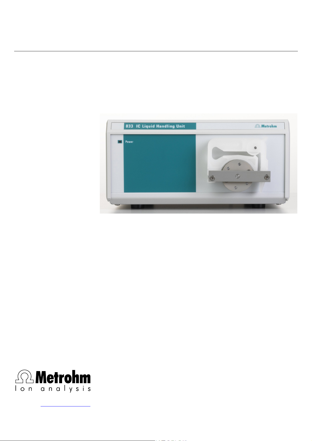
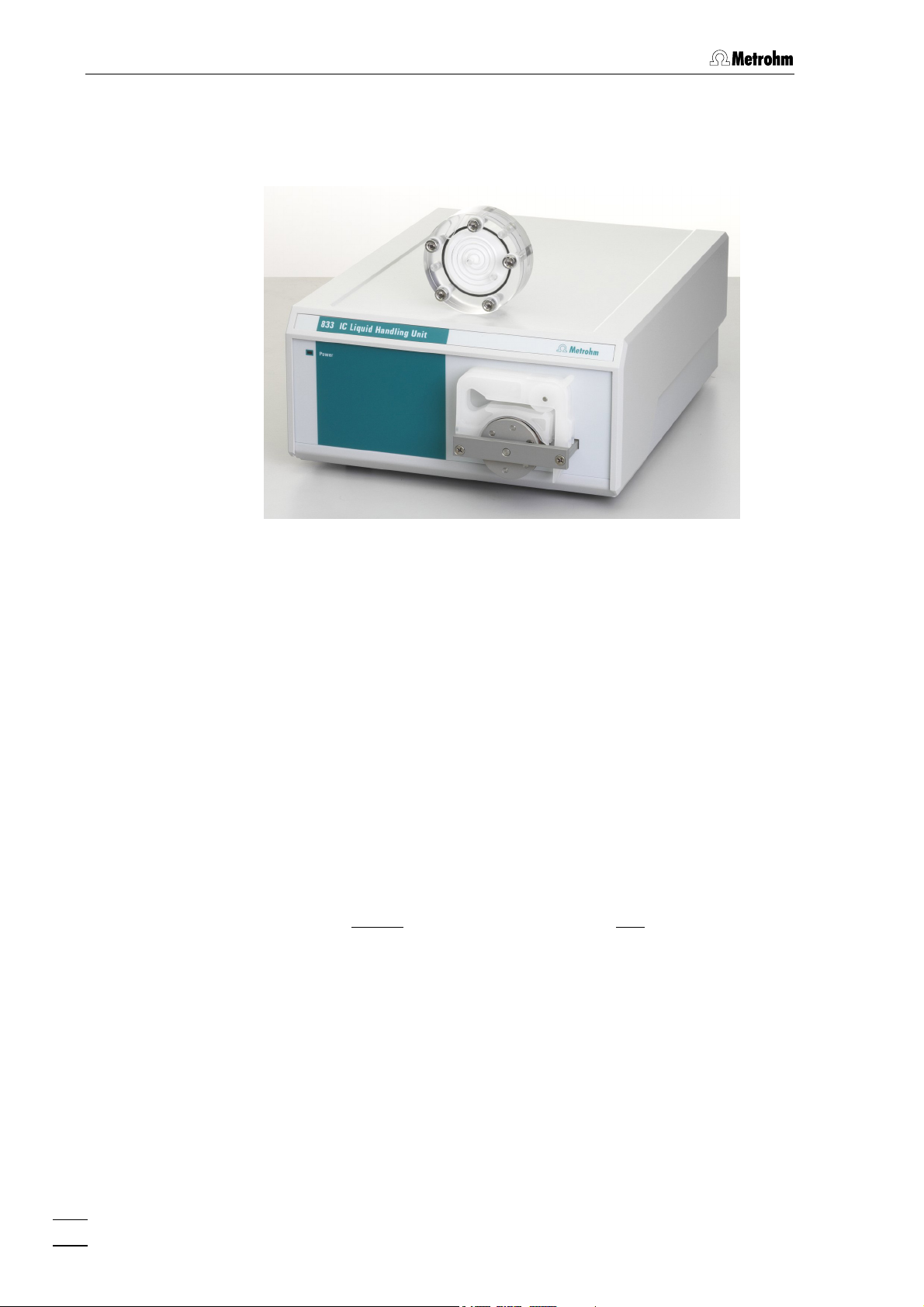
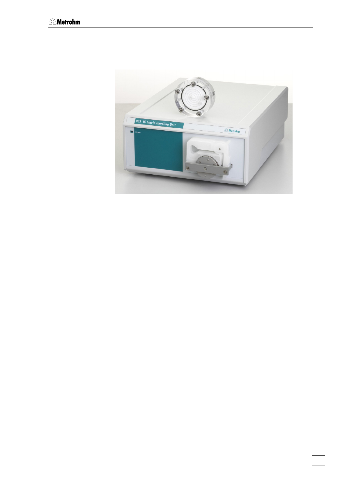
833 IC Liquid Handling Unit
CH-9101 Herisau/Switzerland
E-Mail info@metrohm.com
Internet www.metrohm.com
Instructions for Use
8.833.1003
Page 2

Page 3

CH-9101 Herisau/Switzerland
E-Mail info@metrohm.com
Internet www.metrohm.com
833 IC Liquid Handling Unit
Instructions for Use
8.833.1003 10.2003 / pkl
Page 4

Teachware
Metrohm AG
Oberdorfstrasse 68
CH-9101 Herisau
teachware@metrohm.com
1st Edition 2003
These instructions are protected by copyright. All rights reserved.
Although all the information given in these instructions has been checked with great care, errors
cannot be entirely excluded. Should you notice any mistakes please inform the author at the
address given above.
Page 5

Table of contents
Table of contents
1 Introduction ................................................................ 1
1.1 Instrument description ................................................................................1
1.1.1 833 IC Liquid Handling Pump Unit..................................................................... 1
1.1.2 833 IC Liquid Handling Suppressor Unit ........................................................... 2
1.1.3 833 IC Liquid Handling Sample Preparation Unit.............................................. 3
1.1.4 833 IC Liquid Handling Dialysis Unit.................................................................. 4
1.1.5 833 IC Liquid Handling Ultrafiltration Unit.......................................................... 5
1.2 Parts and controls .......................................................................................6
1.3 Information about these Instructions for Use ............................................8
1.3.1 Arrangement....................................................................................................... 8
1.3.2 Notation and pictograms.................................................................................... 9
1.4 Safety information .....................................................................................10
1.4.1 Electrical safety................................................................................................. 10
1.4.2 General safety rules.......................................................................................... 10
2 Installation ............................................................... 11
2.1 Instrument setup .......................................................................................11
2.1.1 Packaging......................................................................................................... 11
2.1.2 Checks.............................................................................................................. 11
2.1.3 Location ............................................................................................................ 11
2.1.4 Arranging the instruments ................................................................................ 11
2.2 Mains connection ......................................................................................12
2.2.1 Setting the mains voltage................................................................................. 12
2.2.2 Fuses ................................................................................................................ 13
2.2.3 Mains cable ...................................................................................................... 13
2.2.4 Switching the instrument on/off........................................................................ 13
3 Basic instrument ...................................................... 14
3.1 Electrical connection.................................................................................14
3.1.1 Connecting to 761 Compact IC ....................................................................... 14
3.1.2 Connecting to 819 IC Detector......................................................................... 16
3.1.3 Connecting to 830 IC Interface ........................................................................ 18
3.2 Assembly the pump tubing .......................................................................19
3.3 Operation ...................................................................................................23
3.3.1 Switching the instrument on/off........................................................................ 23
3.3.2 Program settings .............................................................................................. 23
4 833 IC Liquid Handling Pump Unit........................... 27
4.1 Connection of the suppressor module ....................................................27
5 833 IC Liquid Handling Suppressor Unit ................. 31
5.1 Connection of the Suppressor module ....................................................31
5.2 Handling the suppressor module .............................................................35
6 833 IC Liquid Handling Sample Preparation Unit ... 36
6.1 Connection to modular IC system for neutralization .............................36
6.1.1 Electrical connections ...................................................................................... 37
6.1.2 Connection of the sample preparation module ............................................... 38
833 IC Liquid Handling Unit / Instructions for Use 8.833.1003
I
Page 6

Table of contents
6.2 Connection to modular IC system for cation separation ........................43
6.2.2 Settings in IC Net.............................................................................................. 47
6.3 Handling the sample preparation module................................................49
7 833 IC Liquid Handling Dialysis Unit .......................50
7.1 Flow diagram for dialysis..........................................................................51
7.2 Electrical connection.................................................................................52
7.2.1 Dialysis without suppression............................................................................ 52
7.2.2 Dialysis with suppression................................................................................. 53
7.3 Settings in IC Net.......................................................................................54
7.3.1 Dialysis without suppression............................................................................ 54
7.3.2 Dialysis with suppression................................................................................. 55
7.4 Assembling the dialysis cell .....................................................................56
7.5 Making the capillary connections.............................................................57
7.5.1 Preparing the 820 IC Separation Center.......................................................... 57
7.5.2 Connection of the dialysis cell ......................................................................... 58
7.6 Optimizing the dialysis..............................................................................63
7.6.1 Determining the rinsing time ............................................................................ 63
7.6.2 Determining the transfer time........................................................................... 63
7.6.3 Determining the dialysis time........................................................................... 64
7.7 Dialysis procedure ....................................................................................66
8 833 IC Liquid Handling Ultrafiltration Unit.............. 68
8.2 Assembling the ultrafiltration cell.............................................................69
8.3 Connect filtration cell ................................................................................70
8.4 Filtration .....................................................................................................74
8.4.1 Selection of possible sample types ................................................................. 74
8.4.2 Filter working life............................................................................................... 74
8.4.3 Filter membrane selection................................................................................ 75
9 Troubleshooting - maintenance............................... 76
9.1 Faults and their remedies .........................................................................76
9.2 Care and maintenance ..............................................................................79
9.2.1 Instrument care ................................................................................................ 79
9.2.2 Maintenance by Metrohm service.................................................................... 79
9.2.3 Shut down ........................................................................................................ 79
9.2.4 Replacing the pump tubing ............................................................................. 80
9.2.5 Changing the filter ............................................................................................ 81
9.2.6 Suppressor module / Sample preparation module ......................................... 82
9.2.7 Dialysis cell....................................................................................................... 88
9.2.8 Ultrafiltration cell ............................................................................................... 90
10 Appendix ................................................................... 91
10.1 Technical data............................................................................................91
10.1.1 Basic instrument: 833 IC Liquid Handling Unit 1.833.0010............................. 91
10.1.2 6.2729.100 Dialysis cell.................................................................................... 94
10.1.3 6.2729.110 Ultrafiltration cell............................................................................ 94
10.2 Standard equipment ..................................................................................95
10.2.1 833 IC Liquid Handling Pump Unit .................................................................. 95
10.2.2 833 IC Liquid Handling Suppressor Unit ......................................................... 96
10.2.3 833 IC Liquid Handling Sample Preparation Unit............................................ 97
10.2.4 833 IC Liquid Handling Dialysis Unit ............................................................... 98
10.2.5 833 IC Liquid Handling Ultrafiltration Unit...................................................... 100
833 IC Liquid Handling Unit / Instructions for Use 8.833.1003
II
Page 7

Table of contents
10.3 Optional accessories ..............................................................................103
10.3.1 Connection cables ......................................................................................... 103
10.3.2 Pumps............................................................................................................. 104
10.3.3 Modules .......................................................................................................... 106
10.4 Validation / GLP .......................................................................................107
10.5 Warranty and Conformity ........................................................................108
10.5.1 Warranty.......................................................................................................... 108
10.5.2 Declaration of Conformity............................................................................... 109
10.5.3 Quality Management Principles ..................................................................... 110
10.6 Index .....................................................................................................111
833 IC Liquid Handling Unit / Instructions for Use 8.833.1003
III
Page 8

Table of contents
List of figures
Fig. 1: Front panel of 833 IC Liquid Handling Unit ............................................... 6
Fig. 2: Rear panelof 833 IC Liquid Handling Unit................................................. 7
Fig. 3: Setting the mains voltage........................................................................ 13
Fig. 4: Connecting the 833 IC Liquid Handling Unit to 761 Compact IC ........... 14
Fig. 5: Connecting the 833 IC Liquid Handling Unit to 819 IC Detector............. 16
Fig. 6: Connecting the 833 IC Liquid Handling Unit to 830 IC Interface ............ 18
Fig. 7: Assembly the pump tubing ..................................................................... 19
Fig. 8: Connections to suppressor module of 820 Separation Center............... 27
Fig. 9: Suppressor module 1.753.0100 .............................................................. 31
Fig. 10: Suppressor module connections for
833 IC Liquid Handling Suppressor Unit................................................. 32
Fig. 11: 1.793.0110 Sample Preparation Module................................................. 36
Fig. 12: Electrical connections for 833 IC Liquid Handling Sample
Preparation Unit and modular IC system for neutralization..................... 37
Fig. 13: Connections at sample preparation module of
the 833 IC Liquid Handling Sample Preparation Unit.............................. 39
Fig. 14: Connection of 833 IC Liquid Handling Sample Preparation Unit
to modular IC system for cation separation ............................................ 44
Fig. 15: 6.2729.100 Dialysis Cell .......................................................................... 50
Fig. 16: Connecting the 833 IC Liquid Handling Dialysis Unit
to a modular dialysis system without suppression ................................. 52
Fig. 17: Connecting the 833 IC Liquid Handling Dialysis Unit
to a modular dialysis system with suppression....................................... 53
Fig. 18: Time program for dialysis without suppression ...................................... 54
Fig. 19: Time program for dialysis with suppression............................................ 55
Fig. 20 Inserting the dialysis cell in the holder..................................................... 57
Fig. 21: Tubing connection system ...................................................................... 58
Fig. 22: 6.2729.110 Ultrafiltration cell ................................................................... 68
Fig. 23 Inserting the ultrafiltration cell in the holder ............................................. 70
Fig. 24: Tubing connection system ...................................................................... 71
Fig. 25: Filter unit PEEK 6.2821.120 ..................................................................... 81
Fig. 26: Actuator assembly................................................................................... 84
Fig. 27: Adjusting the actuator step ..................................................................... 88
833 IC Liquid Handling Unit / Instructions for Use 8.833.1003
IV
Page 9
1.1 Instrument description
1 Introduction
1.1 Instrument description
Within the modular Advanced IC Systems the 833 IC Liquid Handling
Unit is the universal building block for the preliminary preparation and
post-treatment of samples and for transporting auxiliary and rinsing
solutions. It is available in 5 versions that are matched to the most
frequently required applications:
• 2.833.0010 833 IC Liquid Handling Pump Unit
• 2.833.0020 833 IC Liquid Handling Suppressor Unit
• 2.833.0030 833 IC Liquid Handling Sample Preparation Unit
• 2.833.0040 833 IC Liquid Handling Dialysis Unit
• 2.833.0050 833 IC Liquid Handling Ultrafiltration Unit
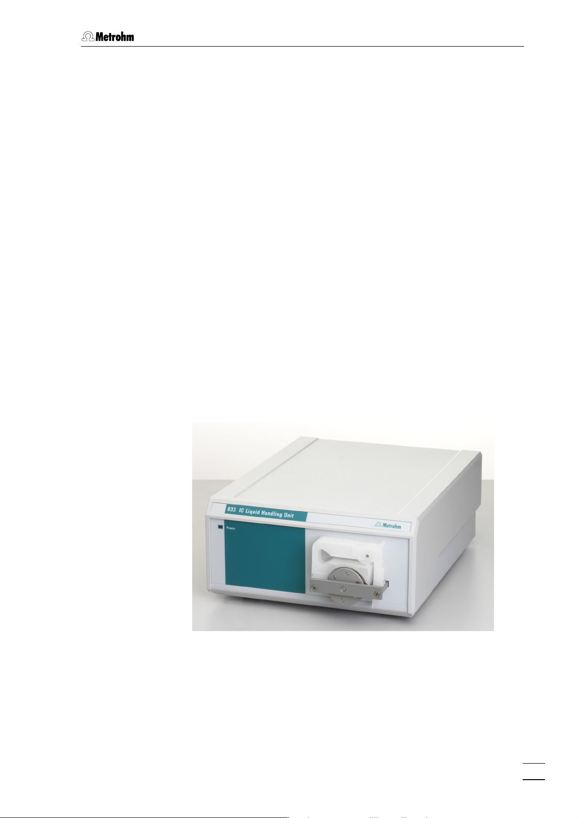
1.1.1 833 IC Liquid Handling Pump Unit
The 833 IC Liquid Handling Pump Unit corresponds to the basic
instrument. It has a 2-channel peristaltic pump and can be included in a
modular Metrohm IC system via a remote interface and remotely
controlled by the IC Net software.
It can transport two solutions simultaneously and is particularly suitable
for the operation of the suppressor module in the 2.820.0230 IC
Separation Center for supplying regeneration and rinsing solution.
833 IC Liquid Handling Unit / Instructions for Use 8.833.1003
1
Page 10
1 Introduction
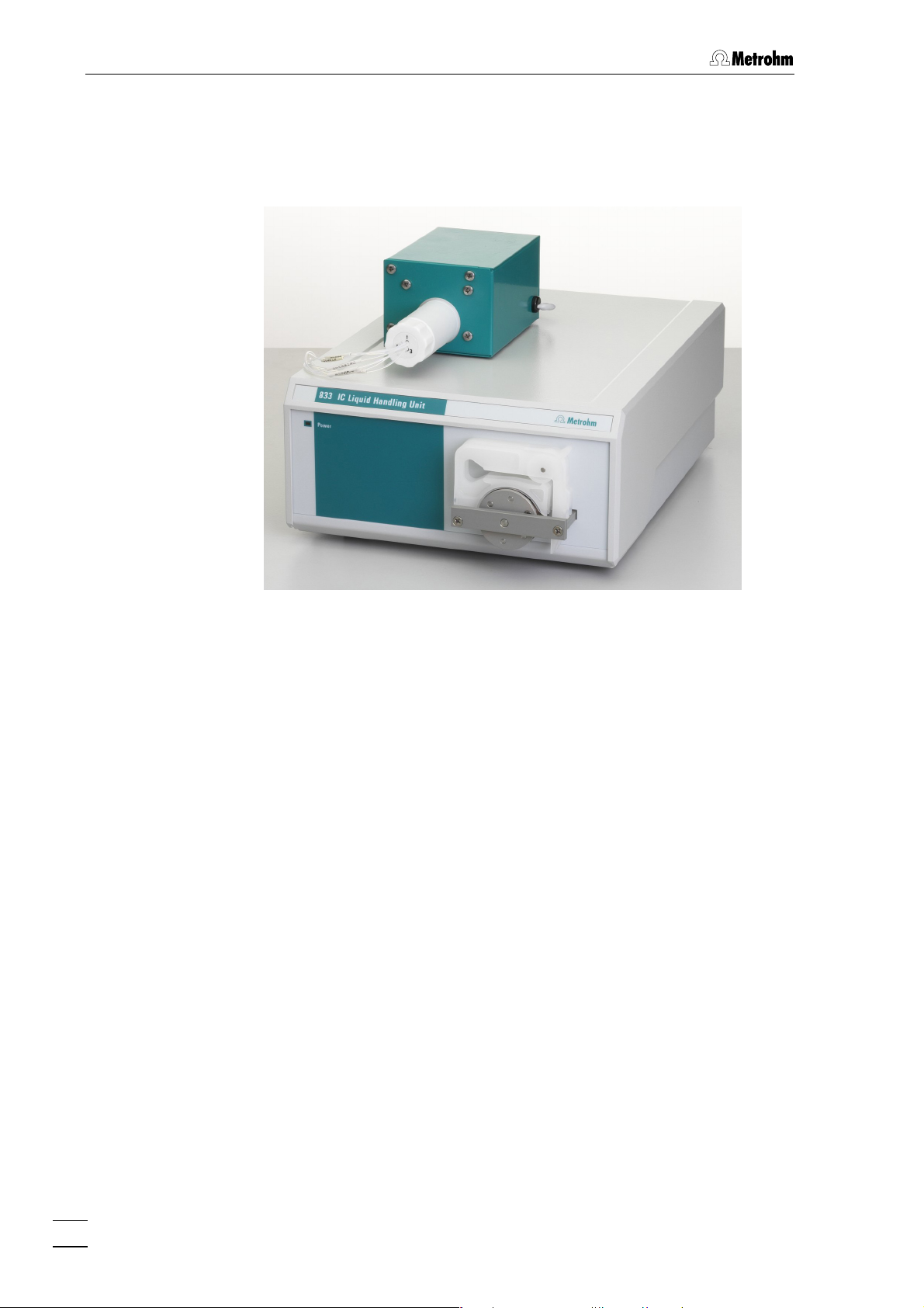
1.1.2 833 IC Liquid Handling Suppressor Unit
As well as the basic instrument, the 833 IC Liquid Handling
Suppressor Unit includes a suppressor module connected to the
basic instrument and also remotely controlled by IC Net.
With the suppressor included in the suppressor module analyses by
ion chromatography with chemical suppression can be carried out. The
suppressor consists of a total of 3 suppressor units which are used in
rotation for suppression, regeneration with sulfuric acid and rinsing with
water. In order that each new chromatogram is recorded under
comparable conditions a freshly regenerated suppressor unit is
normally used. Switching takes place automatically.
The 833 IC Liquid Handling Suppressor Unit is particularly suitable
for retrofitting existing IC systems for chemical suppression in a simple
way. For example, this means that the 833 IC Liquid Handling
Suppressor Unit can be used together with two 819 IC Detectors, two
818 IC Pumps and an 820 IC Separation Center without suppressor
(2.820.0220) to realize a complete 2-channel IC system with only a
single Separation Center.
2
833 IC Liquid Handling Unit / Instructions for Use 8.833.1003
Page 11
1.1 Instrument description
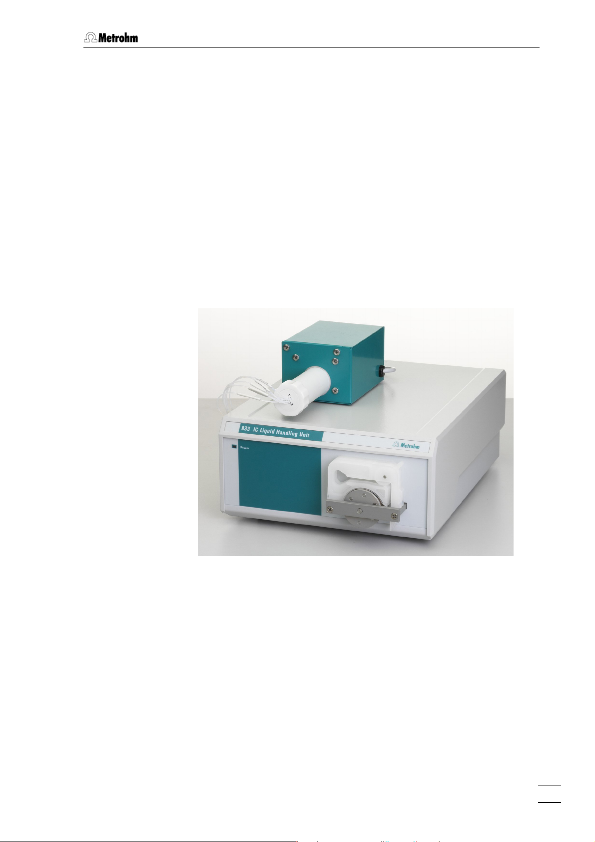
1.1.3 833 IC Liquid Handling Sample Preparation Unit
As well as the basic instrument, the 833 IC Liquid Handling Unit
includes a reactor block (sample preparation module) that is
connected to the basic instrument and also remotely controlled by IC
Net.
With the cation exchanger built-into the sample preparation module
such inline sample preparation steps as neutralization and cation
separation can be carried out for analyses by ion chromatography.
The sample preparation module contains a total of three units which are
used in rotation for cation exchange, regenerated with acid and rinsed
with water. In order that each new chromatogram is recorded under
comparable conditions a freshly regenerated cation exchanger is
normally used. Switching takes place either automatically by the IC
system or manually. As sulfate could interfere with the subsequent IC
analysis, the cation exchanger of the sample preparation module
usually uses perchloric acid (HClO
regeneration.
) instead of sulfuric acid (H2SO4) for
4
The 833 IC Liquid Handling Sample Preparation Unit is particularly
suitable for retrofitting a modular IC system for anion analysis for
sample preparation in a simple way. Two typical applications
(neutralization: exchange of e.g. Na
exchange of e.g. heavy metals for H
Instructions for Use. Although the cation exchange technique used is
comparable with the principle of suppression of the 833 IC Liquid
Handling Suppressor Unit, the 833 IC Liquid Handling Sample
Preparation Unit is not suitable for chemical suppression after the
separation of anions by ion chromatography.
833 IC Liquid Handling Unit / Instructions for Use 8.833.1003
+
for H+ and cation separation:
+
) are described in detail in the
3
Page 12
1 Introduction
1.1.4 833 IC Liquid Handling Dialysis Unit
As well as the basic instrument, the IC Liquid Handling Dialysis Unit
833 includes a dialysis cell upstream from the sample injector.
The 833 IC Liquid Handling Dialysis Unit is used for online sample
preparation in ion chromatography and allows the use of automatic
sample dialysis immediately before sample injection. As well as the 2channel peristaltic pump of the basic instrument for transferring the
sample and acceptor solution from the dialysis cell itself, the ions from
the flowing sample solution are enriched in the stationary acceptor
solution and then injected directly into the IC system. As a result of this
special stopped flow technique, for which an application for a patent
has been made by Metrohm, 100% sample concentration can be
achieved in the acceptor solution and in this way it is possible to carry
out calibration with external standards in a very easy manner.
The operation of the 833 IC Liquid Handling Dialysis Unit requires
the use of an 820 IC Separation Center with one injector and an
additional 833 IC Liquid Handling Pump Unit for the sample tramsport.
These systems, which are described in the Instructions for Use, require
the following instruments:
Operation without
2.819.0110 IC Detector
2.820.0210 IC Separation Center
2.818.0110 IC Pump
2.833.0040 IC Liquid Handling
Dialysis Unit
2.833.0010 IC Liquid Handling
Pump Unit
suppressor
Operation with suppressor
2.819.0110 IC Detector
2.820.0230 IC Separation Center
2.818.0110 IC Pump
2.833.0040 IC Liquid Handling
Dialysis Unit
2.833.0010 IC Liquid Handling
Pump Unit (2 x)
4
833 IC Liquid Handling Unit / Instructions for Use 8.833.1003
Page 13
1.1 Instrument description
1.1.5 833 IC Liquid Handling Ultrafiltration Unit
As well as the basic instrument, the IC Liquid Handling Ultrafiltration
Unit 833 includes a filtration cell upstream from the sample injector.
The 833 IC Liquid Handling Ultrafiltration Unit is an instrument for
online sample preparation in ion chromatography that allows the inline
filtration of the sample immediately before it is injected.
The 833 IC Liquid Handling Ultrafiltration Unit is designed for the
filtration of difficult samples that place special demands on the filtration
effects and sample throughput.
Of course, all versions of the 833 IC Liquid Handling Unit can also be
used with any other commercially available HPLC components.
833 IC Liquid Handling Unit / Instructions for Use 8.833.1003
5
Page 14
1 Introduction
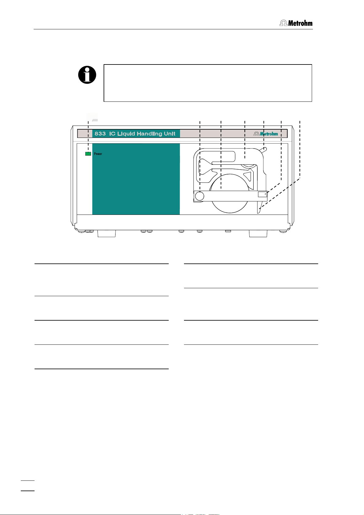
1.2 Parts and controls
In this section you will find the numbers and names of the parts and
controls of the 833 IC Liquid Handling Unit. The numbering is valid for
the whole of these Instructions for Use, i.e. bold numbers in the text
(e.g.
9
) refer to the parts and controls shown here.
Fig. 1: Front panel of 833 IC Liquid Handling Unit
Mains lamp
1
Lights up when instrument is switched
on
Holding pin
2
For inserting the tubing cassettes
32 4 5 6
Contact lever
5
For controlling the contact pressure
Holding clip
6
For clicking the tubing cassette in
place
7
Pump drive
3
Roller head with contact rollers
Tubing cassette
4
For 6.1826.0X0 Pump tubing
6
833 IC Liquid Handling Unit / Instructions for Use 8.833.1003
Spring lever
7
For releasing the tubing cassette
Page 15
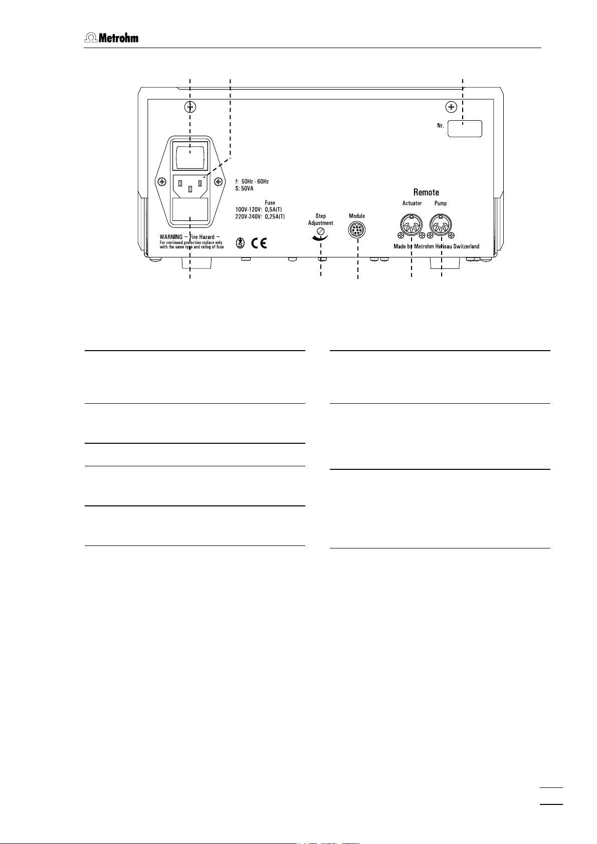
1.2 Parts and controls
8
9
11
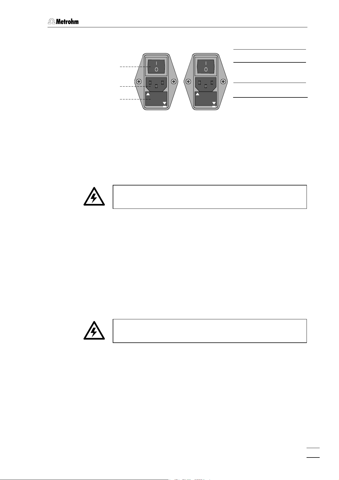
Fig. 2: Rear panelof 833 IC Liquid Handling Unit
Mains switch
8
Switch for switching instrument on/off:
I = ON 0 = OFF
12 13 14
Module
13
Connection for suppressor module
and sample preparation module
10
15
Mains connection
9
Mains connection: see Section 2.2
Serial number
10
Fuse holder
11
Changing the fuses: see Section 2.2.2.
Step adjustment
12
Adjusts the actuator rotor
REMOTE actuator
14
Remote interface for actuator
Connection to 761 Compact IC, 819 IC
Detector or 830 IC Interface
REMOTE pump
15
Remote interface for pump
Connection to 761 Compact IC,
732/819 IC Detector or 762/830 IC
Interface
833 IC Liquid Handling Unit / Instructions for Use 8.833.1003
7
Page 16
1 Introduction
1.3 Information about these Instructions for Use
Please read through these Instructions for Use carefully before you
start to use the 833 IC Liquid Handling Unit. The instructions contain
information and warnings that must be observed by the user in order
to guarantee the safe use of the instrument.
1.3.1 Arrangement
These 8.833.1003 Instructions for Use for the 833 IC Liquid
Handling Unit provide a comprehensive overview of the installation,
start-up, operation and technical specifications of this instrument. They
are arranged in the following way:
Sect. 1 Introduction
General description of the instrument, numbers and
names of the parts and controls, safety information
Sect. 2 Installation
Instrument setup, mains connection
Sect. 3 Basic instrument
Instrument connection, mounting the pump tubing,
control via «IC Net»
Sect. 4 833 IC Liquid Handling Pump Unit
Instrument connection
Sect. 5 833 IC Liquid Handling Suppressor Unit
Instrument connection, suppressor module handling
Sect. 6 833 IC Liquid Handling Sample Preparation Unit
Instrument connection to modular system for cation
separation and modular system for neutralization, sample
preparation module handling
Sect. 7 833 IC Liquid Handling Dialysis Unit
Instrument connection to modular system with manual
sample injection, dialysis procedure, dialysis optimization
Sect. 8 833 IC Liquid Handling Ultrafiltration Unit
Instrument connection, general information about filtration
Sect. 9 Troubleshooting -
Troubleshooting and remedies, care and maintenance
Sect. 10 Appendix
Technical data, standard equipment, options, warranty,
conformity declarations, index
Please use either the Table of Contents or the Index to find any
information you may require.
8
833 IC Liquid Handling Unit / Instructions for Use 8.833.1003
Page 17
1.3 Information about these Instructions for Use
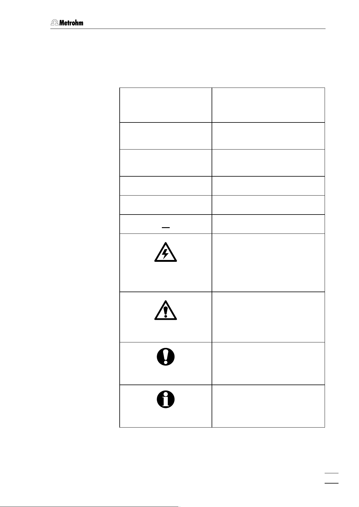
1.3.2 Notation and pictograms
The following notation and pictograms (symbols) are used in these
Instructions for Use:
Pump Menu item, parameter or input
value
in «IC Net» program
SYSTEM STATE Program window
in «IC Net» program
<OK> Button
in «IC Net» program
[ RUN/STOP ] Switch or key
10 Part or control of 833
14 Part or control of 819/820
Danger/Warning
This symbol indicates a possible
risk of death or injury to the user
and possible damage to the
instrument or its components by
electric current.
Danger/Warning
This symbol indicates a possible
risk of death or injury to the user
and possible damage to the
instrument or its components.
Attention
This symbol indicates important
information that you should read
before continuing.
833 IC Liquid Handling Unit / Instructions for Use 8.833.1003
Information
This symbol indicates additional
information and tips which may be
of particular use to you.
9
Page 18
1 Introduction
1.4 Safety information
1.4.1 Electrical safety
Electrical safety when handling the 833 IC Liquid Handling Unit is
guaranteed within the scope of Standard IEC 1010-1 (protection class
1, protection code IP40). The following points must be observed:
• Mains connection
The mains connection must be made in accordance with the
instructions given in Section 2.2.
• Opening the instrument
The housing contains no components which could be set or adjusted
by the user .
When the 833 IC Liquid Handling Unit is connected to the mains
supply the instrument must not be opened, nor should any of its
components be dismantled as otherwise you could come into contact
with current-carrying components. Before opening the instrument
separate it from all current sources and make sure that mains cable
9
has been removed from mains connection socket
!
• Protection against electrostatic charges
Electronic components are sensitive to electrostatic charges and can
be destroyed by a discharge. Before you touch any electronic
components of the 833 IC Liquid Handling Unit you should ground
you and your tools by grasping a grounded object (e.g. the instrument
housing or a radiator) in order to eliminate any electrostatic charges
that may be present.
1.4.2 General safety rules
• Solvent handling
Check the pump tubing and inlet and outlet connections for leaks at
regular intervals. Observe the relevant regulations when handling and
disposing of flammable and/or toxic solutions.
• Regular replacement of pump tubing
Pump tubing is a consumable and must be replaced from time to
time (see Section 9.2.4). Take suitable measures to ensure that any
leak in the pump tubing or connections during unattended and
continuous operation cannot cause any damage (placing the
instrument in a low position, collection trough for escaping liquid).
10
833 IC Liquid Handling Unit / Instructions for Use 8.833.1003
Page 19
2.1 Instrument setup
2 Installation
2.1 Instrument setup
2.1.1 Packaging
The 833 IC Liquid Handling Unit and its separately packed accessories
are supplied in very protective special packaging. These contain
impact-absorbing plastic foam linings contained inside a blue plastic
film; these are molded to fit the individual components. The instrument
itself is contained in a dustproof evacuated polyethylene bag. Please
store all this special packaging; it is the only way in which the safe
transport of the instrument can be guaranteed.
2.1.2 Checks
Please check that the delivery is complete and undamaged
immediately on receipt (compare with delivery note and list of
accessories given in Section 10.2). If transport damage is evident
please refer to the information given in Section 10.5.1 "Warranty".
2.1.3 Location
Place the instrument on a vibration-free bench in a favorable position
for operation and protected from corrosive atmospheres and
contamination by chemicals.
2.1.4 Arranging the instruments
Other IC instruments (e.g. 818, 819, 820) can be stacked on top of the
833 IC Liquid Handling Unit. It is best to place it beside the modular IC
system or at the bottom of the stack.
The 833 IC Liquid Handling Unit should always be at the bottom so
that any leaks which may occur in the pump tubing or connections
cannot cause any great damage by escaping liquids (e.g. acids).
833 IC Liquid Handling Unit / Instructions for Use 8.833.1003
11
Page 20
2 Installation
2.2 Mains connection
Please observe the following rules when connecting the instrument to
the electricity supply. If the instrument is operated with an incorrectly
set mains voltage and/or an incorrect mains fuse then it represents a
fire hazard!
2.2.1 Setting the mains voltage
Before you switch on the 833 Liquid Handling Unit for the first time
please check that the mains voltage set on the instrument (see Fig. 3)
corresponds to your local mains voltage. If this is not
must alter the mains voltage as follows:
1 Pull out mains cable
Remove the mains cable from mains supply connection 9 of the
833 IC Liquid Handling.
the case then you
2 Remove the fuse holder
Use a screwdriver to loosen fuse holder 11 beneath the mains
supply connection and remove it completely.
3 Check the fuse
Carefully remove the built-in fuse for the intended voltage from
the fuse holder and check its specifications (the position of the
fuse in the fuse holder is indicated by the white arrow beside the
voltage range):
100…120 V 0.5 A (slow blow) Metrohm No. U.600.0013
220…240 V 0.25 A (slow blow) Metrohm No. U.600.0010
4 Insert fuse
Exchange the fuse if necessary and replace it in the fuse holder.
5 Insert fuse holder
Depending on the required mains voltage, insert the fuse holder
in the 833 IC Liquid Handling Unit 833 so that the appropriate
voltage range can be read normally and the adjacent white
arrow points to the white bar printed beneath the fuse holder
(see Fig. 3).
12
833 IC Liquid Handling Unit / Instructions for Use 8.833.1003
Page 21
2.2 Mains connection
–
V
V
Fig. 3: Setting the mains voltage
2.2.2 Fuses
220 –240
100
120
8 Mains switch
8
9 Mains
connection
9
11
220 - 240 V
100 - 120 V
-
220
240 V
-
100
120 V
11 Fuse holder
The fuse holder of the 833 IC Liquid Handling Unit contains one of the
two fuses 0.5 A/slow blow for 100…120 V or 0.25 A/slow blow for
220…240 V.
Make sure that the instrument is never operated with a different type of
fuse as otherwise it represents a fire hazard!
Checking and replacing a fuse is described in Section 2.2.1.
2.2.3 Mains cable
The instrument is supplied with one of the following mains cables:
• 6.2122.020 with SEV 12 plug (Switzerland, …)
• 6.2122.040 with CEE(7), VII plug (Germany, …)
• 6.2133.070 with NEMA 5-15 (USA, …)
which has 3 wires and is fitted with a plug with a grounding pin. If a
different plug has to be attached then the yellow/green wire (IEC
standard) must be connection to the grounding pin.
Any break in the grounding inside or outside the instrument will make
it dangerous!
Insert the mains cable plug in mains connection 9 of the 833 IC Liquid
Handling Unit (see Fig. 2).
2.2.4 Switching the instrument on/off
The 833 IC Liquid Handling Unit is switched on and off with mains
switch 8 (see Fig. 2). When the instrument is switched on mains lamp 1
lights up.
833 IC Liquid Handling Unit / Instructions for Use 8.833.1003
13
Page 22
3 Basic instrument
3 Basic instrument
3.1 Electrical connection
Always switch off the 833 IC Liquid Handling Unit and the instrument
to which the Liquid Handling Unit is to be connected before you make
an electrical connection.
The 833 Liquid Handling Unit can be operated and remotely controlled
by a 761 Compact IC, an 819 IC Detector and in a modular system
via the 830 IC Interface.
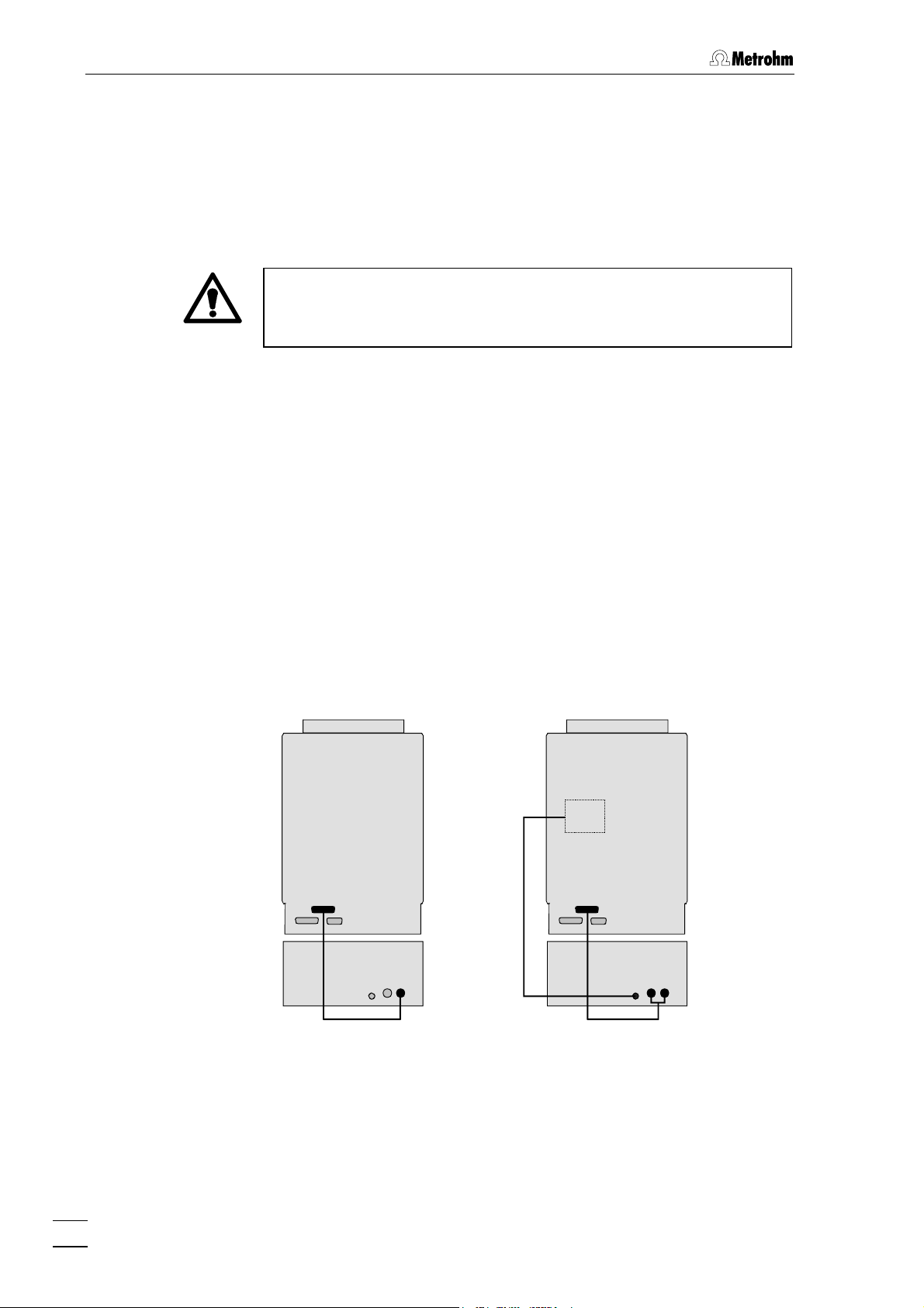
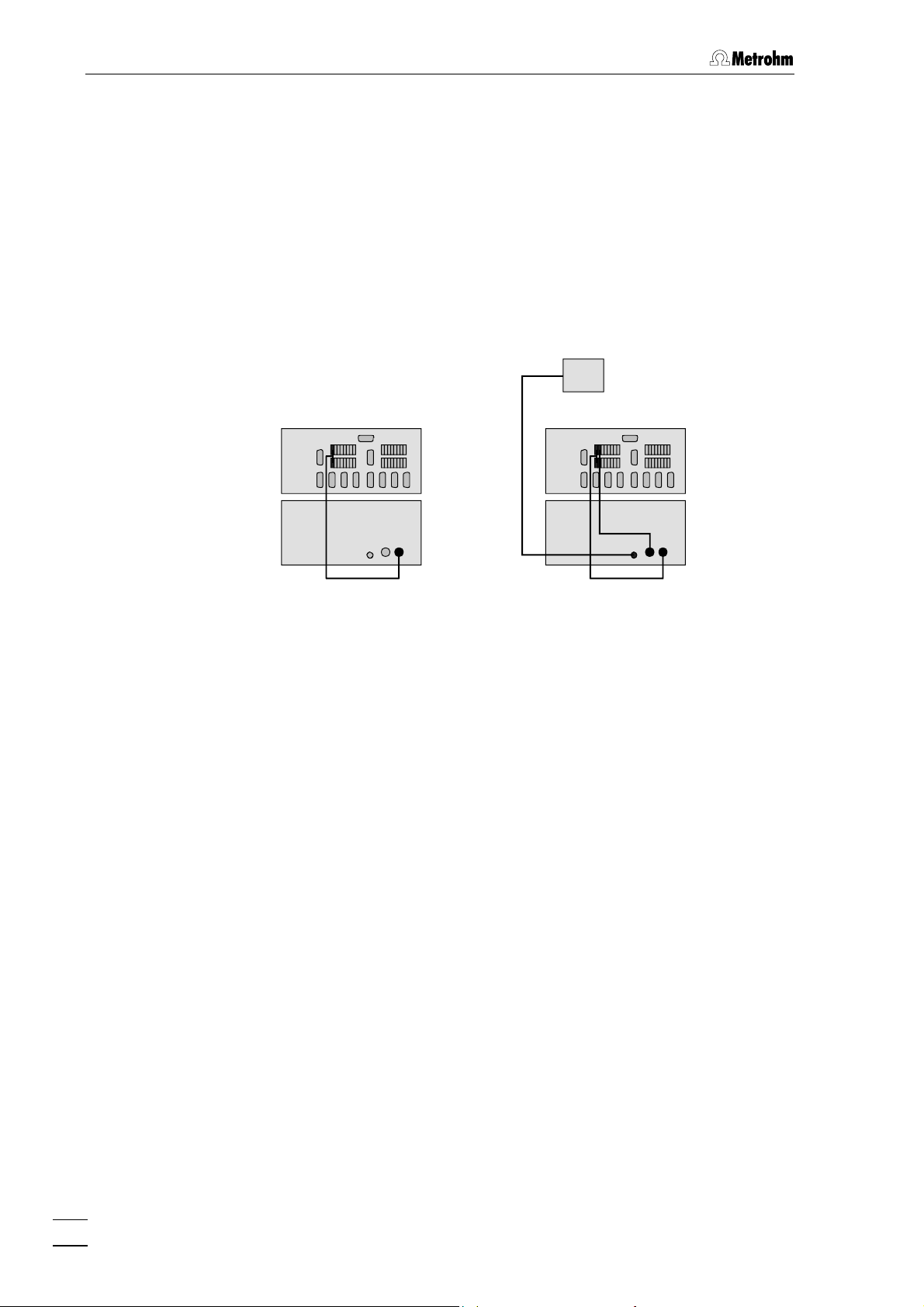
3.1.1 Connecting to 761 Compact IC
Connect the remote connection of the 761 Compact IC with the
required remote connections 14 and 15 on the 833 IC Liquid Handling
Unit. The peristaltic pump of the Liquid Handling Unit is controlled via
remote connection Remote Pump 15, this must always be connected.
The connection Remote Actuator 14 is only required for the 833 IC
Liquid Handling Suppressor Unit and the 833 IC Liquid Handling
Sample Preparation Unit; it is used to switch the suppressor or
sample preparation module. The particular modules are connected
to the socket Module 13.
761
833
816
Cable
to
Module
761
833
816
6.2143.200
6.2143.210
Fig. 4: Connecting the 833 IC Liquid Handling Unit to 761 Compact IC
14
833 IC Liquid Handling Unit / Instructions for Use 8.833.1003
Page 23

3.1 Electrical connection
The following cables are available for these connections:
• 6.2143.200 Cable for one remote connection via
Remote line 1.
To connect a Liquid Handling Unit with a peristaltic pump, e.g.:
2.833.0010 IC Liquid Handling Pump Unit
2.833.0050 IC Liquid Handling Ultrafiltration Unit
• 6.2143.210 Cable for two remote connections via
Remote lines 1 and 2.
To connect a Liquid Handling Unit with a peristaltic pump and a
suppressor or sample preparation module, e.g.:
2.833.0020 IC Liquid Handling Suppressor Unit
2.833.0030 IC Liquid Handling Sample Preparation Unit
or
To connect two peristaltic pumps, e.g. for dialysis:
2.833.0010 IC Liquid Handling Pump Unit
2.833.0040 IC Liquid Handling Dialysis Unit
• 6.2143.220 Cable for three remote connections via
Remote lines 1, 2 and 4.
To connect up to three Liquid Handling Units, e.g. for dialysis with
suppression:
2x 2.833.0010 IC Liquid Handling Pump Unit
and 1x 2.833.0040 IC Liquid Handling Dialysis Unit
(three peristaltic pumps are switched on and off)
or
Ultrafiltration with suppression
1x 2.833.0020 IC Liquid Handling Suppressor Unit
and 1x 2.833.0050 IC Liquid Handling Ultrafiltration Unit
(two peristaltic pumps are switched on and off
and the sample preparation module is switched
on)
The remote line via which the control of the Liquid Handling Unit takes
place is determined by the wiring of the cable. The active remote line is
printed on the 833-end of the cable. This remote line must be set
accordingly in the control software «761 Compact IC» or «IC Net», see
Section 4.3.7 In the «761 Compact IC» Instructions for Use and Section
6.5.3 in the «IC Net» Instructions for Use.
833 IC Liquid Handling Unit / Instructions for Use 8.833.1003
15
Page 24
3 Basic instrument
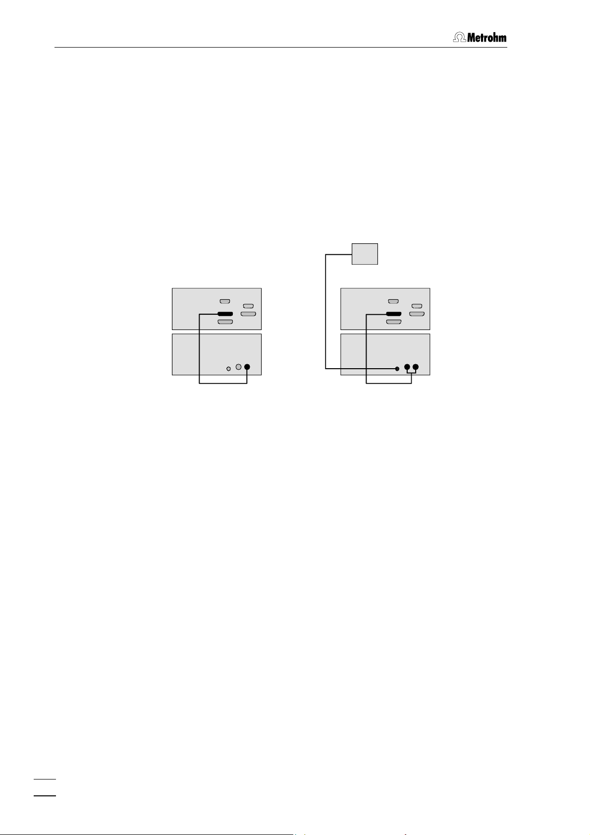
3.1.2 Connecting to 819 IC Detector
Connect the remote connection of the 819 IC Detector to the necessary
remote connections 14 and 15 on the 833 IC Liquid Handling Unit. The
peristaltic pump of the Liquid Handling Unit is controlled via remote
connection Remote Pump 15, this must always be connected. The
connection Remote Actuator 14 is only required for the 833 IC Liquid
Handling Suppressor Unit and the 833 IC Liquid Handling Sample
Preparation Unit; it is used to switch the suppressor or sample
preparation module. The particular modules are connected to the
socket Module 13.
819 819
833
816
6.2143.200
Cable
to
Module
833
816
6.2143.210
Fig. 5: Connecting the 833 IC Liquid Handling Unit to 819 IC Detector
The following cables are available for these connections:
• 6.2143.200 Cable for one remote connection via
Remote line 1.
To connect a Liquid Handling Unit with a peristaltic pump, e.g.:
2.833.0010 IC Liquid Handling Pump Unit
2.833.0050 IC Liquid Handling Ultrafiltration Unit
• 6.2143.210 Cable for two remote connections via
Remote lines 1 and 2.
To connect a Liquid Handling Unit with a peristaltic pump and a
suppressor or sample preparation module, e.g.:
2.833.0020 IC Liquid Handling Suppressor Unit
2.833.0030 IC Liquid Handling Sample Preparation Unit
or
To connect two peristaltic pumps, e.g. for dialysis:
2.833.0010 IC Liquid Handling Pump Unit
2.833.0040 IC Liquid Handling Dialysis Unit
16
833 IC Liquid Handling Unit / Instructions for Use 8.833.1003
Page 25

3.1 Electrical connection
• 6.2143.220 Cable for three remote connections via
Remote lines 1, 2 and 4.
To connect up to three Liquid Handling Units, e.g. for dialysis with
suppression:
2x 2.833.0010 IC Liquid Handling Pump Unit
and 1x 2.833.0040 IC Liquid Handling Dialysis Unit
(three peristaltic pumps are switched on and off)
or
Ultrafiltration with suppression
1x 2.833.0020 IC Liquid Handling Suppressor Unit
and 1x 2.833.0050 IC Liquid Handling Ultrafiltration Unit
(two peristaltic pumps are switched on and off
and the sample preparation module is switched
on)
The remote line via which the control of the Liquid Handling Unit takes
place is determined by the wiring of the cable. The active remote line is
printed on the 833-end of the cable. This remote line must be set
accordingly in the control software «IC Net», see Section 6.4.3 of the
«IC Net» Instructions for Use.
833 IC Liquid Handling Unit / Instructions for Use 8.833.1003
17
Page 26
3 Basic instrument
3.1.3 Connecting to 830 IC Interface
Connect one of the event lines of the 830 IC Interface with one of the
required remote connections 14 and 15 on the 833 IC Liquid Handling
Unit. The peristaltic pump of the Liquid Handling Unit is controlled via
remote connection Remote Pump 15, this must always be connected.
The connection Remote Actuator 14 is only required for the 833 IC
Liquid Handling Suppressor Unit and the 833 IC Liquid Handling
Sample Preparation Unit; it is used to switch the suppressor or
sample preparation module. The particular modules are connected
to the socket Module 13.
830
833
816
Cable
to
Module
6.2128.180
830
833
816
6.2128.180
6.2128.180
Fig. 6: Connecting the 833 IC Liquid Handling Unit to 830 IC Interface
For each remote connection one 6.2128.180 Cable is required. At the
830 IC Interface 2 × 7 remote connections can be assembled. Which
event lines are used for this does not matter; when a system is set up
the assignment must only be given correctly in the «IC Net» software
when creating a system, see Section 6.1 of the «IC Net» Instructions for
Use.
18
833 IC Liquid Handling Unit / Instructions for Use 8.833.1003
Page 27
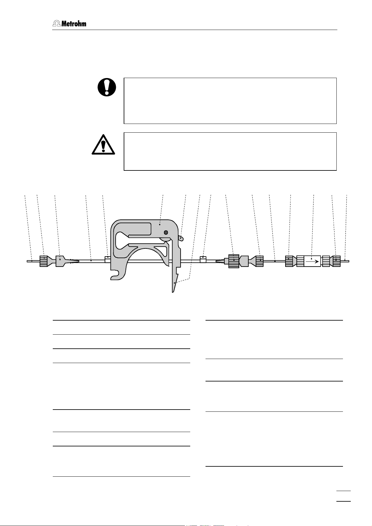
3.2 Assembly the pump tubing
3.2 Assembly the pump tubing
Pump tubing is a consumable whose working life depends on the
contact pressure. This is why when the pump is switched off for a long
time, the tubing cassette should be lifted by fully loosening spring
lever
7
on the right-hand side (in this way the correctly set optimal
contact pressure is retained).
The 6.1826.0X0 Pump tubing consists of PVC or PP and must
therefore not be rinsed with solvents that contain acetone. In this case
you should either use different pump tubing or use a different pump
for rinsing.
18 17 16 4 519
Tubing cassette
4
Contact lever
5
Spring lever
7
6.1803.0X0 Aspiration
16
tubeing/capillary
PTFE tubing/capillary, depends on
version, see Section 10.2 Standard
equipment
20 22 21 20 17
Fig. 7: Assembly the pump tubing
7
Stopper
20
The color of the stopper indicates the
material and dimensions of the pump
tubing, see Tab. 1.
6.2744.160 PEEK Coupling
21
with tubing security device
6.2821.120 PEEK Filter unit
22
not contained in all versions, see
Section 10.2 Standard equipment
17 1716
23
6.2744.010 PEEK compression
17
fitting
6.2744.034 PEEK coupling
18
6.1826.0X0 Pump tubing
19
various tubing is available, depending
on the application, see Tab. 1.
833 IC Liquid Handling Unit / Instructions for Use 8.833.1003
Discharge capillary
23
delivery side for connection to:
suppressor module
sample preparation module
dialysis cell
ultrafiltration cell
19
Page 28
3 Basic instrument
1 Remove tubing cassettes
• Loosen the two tubing cassettes 4 by pressing in spring lever
7 of holding clip 6 and unhinge them from holding pin 2 of
the 833 IC Liquid Handling Unit (see Fig. 1).
2 Insert pump tubing
• Press contact lever 5 on the two tubing cassettes down as far
it will go.
• Insert pump tubing into each tubing cassette as shown in
Fig. 7.
Stopper must click into position in the corresponding holder
on the left-hand side of the tubing cassette.
3 Attach tubing cassettes
• Hinge the tubing cassettes on holding pin and press down
on the right –hand side until spring lever clicks into position
in holding clip 6. Take care that the pump tubing does not
kink.
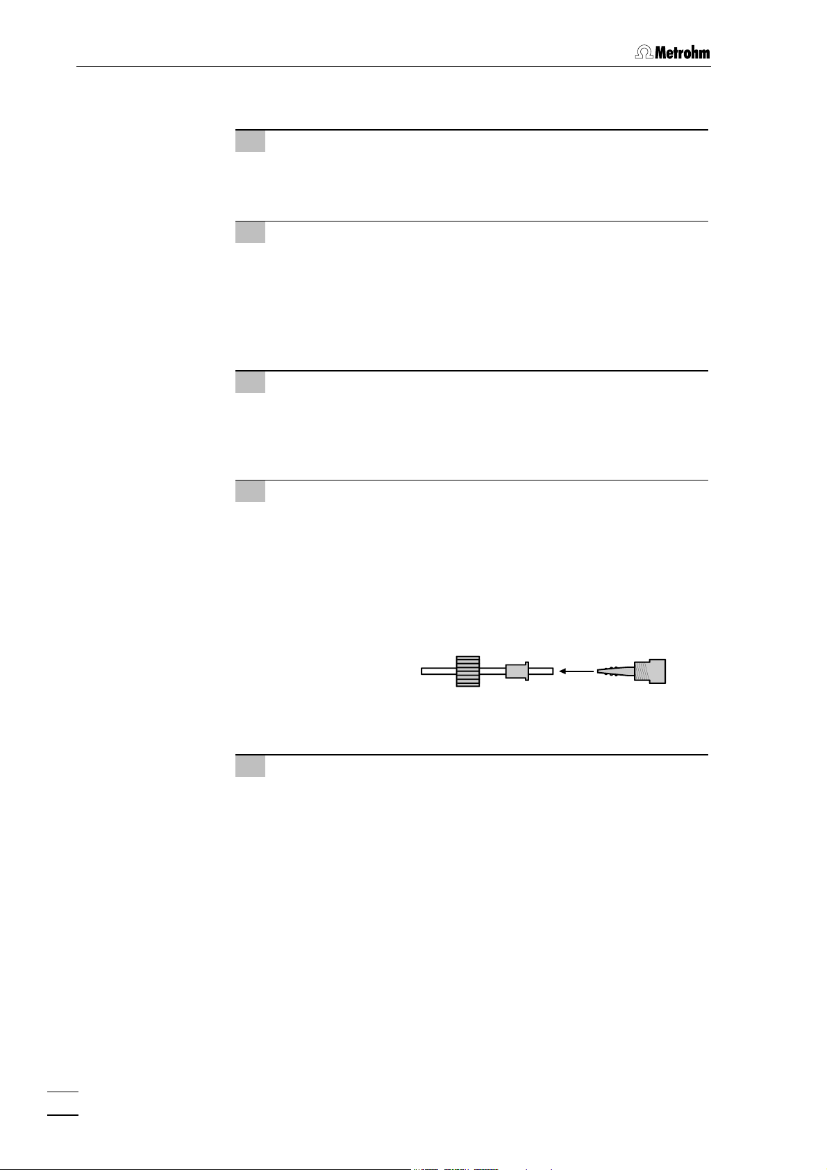
4 Attach coupling to pump tubing
• Attach PEEK coupling 18 to the aspiration end of pump
tubing 19 for both channels (see Fig. 7).
•
Mount PEEK coupling 21 with the tubing security device
(6.2744.160) to the delivery end of pump tubing 19 for both
channels.
This is done by dismantling the tubing security device and
first pushing the sleeve nut and the compression piece onto
the tubing.
Attach the tubing to the PEEK coupling and screw the sleeve
nut onto the coupling in order to secure the tubing.
5 Mounting of filter unit
• If contained in the standard equipment (see Section 10.2
Standard equipment), screw 6.2821.120 PEEK filter unit 22
onto PEEK coupling 21 (6.2744.160) by using two PEEK
compression fittings 17 (6.2744.010) and a piece of
aspiration tubing/capillary 16 (6.1803.0X0) at the delivery end
of pump tubing 19.
Setting the contact pressure correctly:
Press contact lever 5 until the solutions are just aspirated. Then press
the contact lever up by 1 further click to achieve the optimum contact
pressure.
20
833 IC Liquid Handling Unit / Instructions for Use 8.833.1003
Page 29
3.2 Assembly the pump tubing
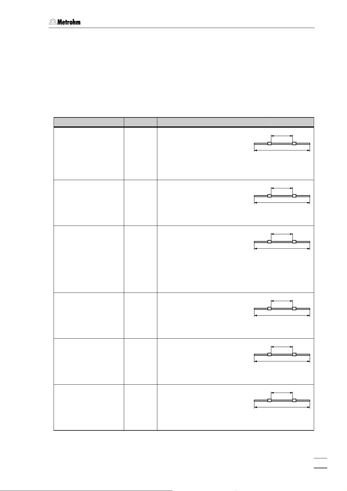
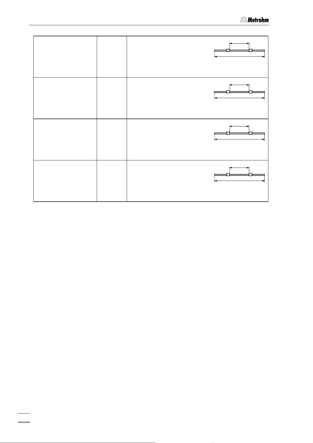
In addition to the correct contact pressure, the delivery rate of the 833
IC Liquid Handling Unit depends primarily on the inner diameter of
pump tubing 19. Different pump tubing can be used depending on the
application.
The following table provides information about the properties and use
of the available pump tubing.
Tab. 1: Using 6.1826.0X0 Pump tubing
Used with Order no. Description
2.833.0030 IC Liquid
Handling Sample
Preparation Unit:
both channels
6.1826.010 Pump tubing
PVC (Tygon
ST) with 2 permanently
mounted white-white stoppers;
i.d. = 1.02 mm ± 0.05 mm,
Delivery rate
1.41 mL/min (20 min
1.69 mL/min (24 min
optional 6.1826.020 Pump tubing
PVC (Tygon
ST) with 2 permanently
mounted blue-blue stoppers;
i.d. = 1.65 mm ± 0.05 mm,
Delivery rate
3.75 mL/min (20 min
4.50 mL/min (24 min
2.833.0040 IC Liquid
Handling Dialysis Unit:
channel for supplying
acceptor solution
2.833.0050 IC Liquid
Handling Ultrafiltration
Unit:
channel for transferring
filtrate to sample loop
2.833.0040 IC Liquid
Handling Dialysis Unit:
channel for supplying
sample
6.1826.030 Pump tubing
PVC (Tygon
ST) with 2 permanently
mounted orange-yellow stoppers;
i.d. = 0.51 mm ± 0.05 mm,
Delivery rate
0.40 mL/min (20 min
0.48 mL/min (24 min
6.1826.040 Pump tubing
PVC (Tygon
mounted black-black stoppers;
i.d. = 0.76 mm ± 0.05 mm,
Delivery rate
ST) with 2 permanently
0.75 mL/min (20 min
0.90 mL/min (24 min
150
-1
)
-1
)
-1
)
-1
)
-1
)
-1
)
-1
)
-1
)
400
150
400
150
400
150
400
2.833.0010 IC Liquid
Handling Pump Unit,
2.833.0020 IC Liquid
Handling Suppressor
Unit:
both channels
6.1826.050 Pump tubing
PVC (Tygon
mounted white-yellow stoppers;
i.d. = 0.57 mm ± 0.05 mm,
Delivery rate
0.52 mL/min (24 min
optional 6.1826.060 Pump tubing
PP (PharMed
mounted orange-yellow stoppers;
i.d. = 0.51 mm ± 0.05 mm,
Delivery rate
0.56 mL/min (24 min
833 IC Liquid Handling Unit / Instructions for Use 8.833.1003
ST) with 2 permanently
0.43 mL/min (20 min
) with 2 permanently
0.47 mL/min (20 min
150
-1
)
-1
)
-1
)
-1
)
400
150
400
21
Page 30
3 Basic instrument
2.833.0050 IC Liquid
Handling Ultrafiltration
Unit:
channel for transferring
sample to ultrafiltration cell
6.1826.070 Pump tubing
PVC (Tygon
ST) with 2 permanently
mounted yellow-yellow stoppers;
i.d. = 1.42 mm ± 0.05 mm,
Delivery rate
2.55 mL/min (20 min
3.06 mL/min (24 min
optional 6.1826.110 Pump tubing long-life
PVC (Tygon
mounted orange-yellow stoppers;
i.d. = 0.51 mm ± 0.0102 mm,
Delivery rate
LFL) with 2 permanently
0.40 mL/min (20 min
0.48 mL/min (24 min
optional 6.1826.120 Pump tubing long-life
PVC (Tygon
mounted orange-white stoppers;
i.d. = 0.59 mm ± 0.05 mm,
Delivery rate
LFL) with 2 permanently
0.44 mL/min (20 min
0.53 mL/min (24 min
optional 6.1826.130 Pump tubing long-life
PVC (Tygon
mounted white-white stoppers;
i.d. = 1.02 mm ± 0.0127 mm,
Delivery rate
LFL) with 2 permanently
1.41 mL/min (20 min
1.69 mL/min (24 min
150
-1
)
-1
)
-1
)
-1
)
-1
)
-1
)
-1
)
-1
)
400
150
400
150
400
150
400
22
833 IC Liquid Handling Unit / Instructions for Use 8.833.1003
Page 31

3.3 Operation
R
3.3 Operation
The 833 IC Liquid Handling Unit is operated completely via the
Metrohm «IC Net» software.
This Section only described the most important functions and settings
for operating the 833 IC Liquid Handling Unit. Further information is
given in the Instructions for Use of the «IC Net» and in the online help
for the program.
3.3.1 Switching the instrument on/off
Remote control of the 833 IC Liquid Handling Unit by the software
requires that the instruments has been installed correctly as described
in Section 2.
Switching the instrument on/off
The 833 IC Liquid Handling Unit is switched on and off with
mains switch 8 on the rear panel of the instrument (see Fig. 2):
I Instrument switched on
0 Instrument switched off
POWE
When the instrument has been switched on mains lamp 1 lights
up to show that it is ready for use.
3.3.2 Program settings
The 833 IC Liquid Handling Unit is operated completely via the
Metrohm «IC Net» software.
This section only describes the most important functions and settings
for operating the 833 IC Liquid Handling Unit. Further information is
given in the Instructions for Use of the «IC Net» and in the online help
for the program.
3.3.2.1 833 IC Liquid Handling Unit icon
2.833.00X0 IC Liquid Handling Unit
For differentiating between which version of the 833 is indicated by the
instrument icon a tool tip with the name of the corresponding
instrument appears when the mouse cursor is placed on the particular
icon.
833 IC Liquid Handling Unit / Instructions for Use 8.833.1003
23
Page 32

3 Basic instrument
3.3.2.2 Settings in the window "833 IC Liquid Handling Unit"
Selection of this menu item with the right-hand mouse key or a doubleclick on the 833 instrument icon opens the window
Unit for parameter settings. It consists of three tabs: Manual, Program
Links.
and
833 IC Liquid Handling
Depending on the version, the title line of the parameter settings
window shows
Preparation Unit
833 IC Pump Unit, 833 IC Suppressor Unit, 833 IC Sample
, 833 IC Dialysis Unit or 833 IC Ultrafiltration Unit and (in
brackets) the name of the system folder and the system file.
Manual
The tab
Manual of the window 833 IC Liquid Handling Unit is used for
manually operating the peristaltic pump and the suppressor or sample
prep module.
Pump (available with all versions)
<On> Start pump drive.
<Off> Stop pump drive.
Suppressor (only available with 833 IC Suppressor Unit)
<Step> Rotate suppressor to the next position. The
time since the last step action is displayed in
the field beside the
Actuator (only available with 833 IC Sample Preparation
Unit)
<Step> Rotate sample preparation module to the next
<Step> button.
position. The time since the last step action is
displayed in the field beside the
24
833 IC Liquid Handling Unit / Instructions for Use 8.833.1003
<Step> button.
Page 33

3.3 Operation
Start pump with startup hardware
Automatic start of pump drive with Startup
hardware
.
Time program
A user-specific time program can be entered on the tab
833 IC Liquid Handling Unit window. Depending on the settings made in
Start mode window (for details see Section 4.4.3 8.110.8281
the
Program in the
Instructions for Use for the Metrodata «IC Net 2.3» software), this
program is started automatically either at the start of the determination
(
Start with determination) or when the sample is injected (Start with inject).
Time (1st column) Time at which program instruction is applied.
Entry range:
0.0 ... 999.9 min
If no time is entered, the program instruction is
applied together with the last instruction with
time entry.
Command (2nd. column) Program instruction (see below).
Parameter (3rd column) Parameter for program instruction (see below).
ENABLED Enable program start (a disabled program is
not started).
<Add> Add new program instruction.
<Delete> Delete selected program instruction.
<Verify> Test the time program (error messages are
displayed if program is wrong).
833 IC Liquid Handling Unit / Instructions for Use 8.833.1003
25
Page 34

3 Basic instrument
List of program instructions
The following program instructions can be added to the time
program on the
Instruction Parameter entry Meaning
Pump on, off Switch on or off the pump drive.
Step Rotate suppressor or sample prep
Program page:
(available for
all versions)
module to the next position.
(only available for
Unit and 833 IC Sample Prep Unit)
833 IC Suppressor
Links
Links tab of the 833 IC Pump Unit is used for Event line selection (for
The
details see Instructions for Use of «IC Net»).
26
833 IC Liquid Handling Unit / Instructions for Use 8.833.1003
Page 35

4.1 Connection of the suppressor module
4 833 IC Liquid
Handling Pump Unit
This version is mainly used for supplying a Metrohm Suppressor
Module MSM built into a 2.820.0X30 IC Separation Center with
regeneration and rinsing solutions. The Metrohm Suppressor Module
MSM is described in detail in Section 2.9.7 of the 819/820 Instructions
for Use.
4.1 Connection of the suppressor module
In order to protect the suppressor module against foreign particles an
inline filter is mounted between the 833 IC Liquid Handling Unit and
the inlet capillary of the suppressor module, see Fig. 7. The most
suitable unit is the 6.2821.120 Filter unit PEEK included in the
standard equipment.
H2SO4
Waste
The suppressor module is connected to the 833 IC Liquid Handling
Pump Unit in accordance with Section 2.9.7 of the 819/820 Instructions
for Use. The most important points are described again below, with
underlined numbers ##
819/820 Instructions for Use:
Eluent
64
65
66
1
2
3
67
Waste
69
68
referring to the parts and controls in the
64
Suppressor inlet
capillary for eluent
65 Suppressor inlet
Detector
H2O
capillary for H
66 Suppressor outlet
capillary for H
67 Suppressor outlet
capillary for H
68 Suppressor inlet
capillary for H
69 Suppressor outlet
capillary for eluent
2SO4
2SO4
2
2
O
O
Fig. 8: Connections to suppressor module of 820 Separation Center
833 IC Liquid Handling Unit / Instructions for Use 8.833.1003
27
Page 36

4 833 IC Liquid Handling Pump Unit
1 Connect column to injector
• Remove end caps from column 53.
• without column heating:
Screw inlet end of separating column 53
to column connection capillary 50
(note flow direction)
mounted on the injector.
• with column heating:
Prepare column heating according to Section 2.9.2 of the
819/820 Instructions for Use and screw column connection
capillary 50
compression fitting to injection valve 51
(see Fig. 20, 819/820 Instructions for Use) with a
.
• With precolumn:
Install precolumn according to the supplied leaflet between
inlet of the separating column and the injection valve.
2 Rinse column
• Place a beaker beneath the column outlet.
• Start 818 IC Pump in «IC Net» with suitable flow (see leaflet of
the column) and rinse column for ca. 10 min with eluent.
• Stop 818 IC Pump.
3 Connect column to suppressor module (Suppressor
connection 1)
• Cut inlet capillary 64
module 70
to the required length. Use the 6.2126.080
(marked with "Eluent") of suppressor
Capillary cutter available as an option.
• without column heating
Screw inlet capillary 64
column 53
using a 6.2744.010 compression fitting.
on to the outlet end of separating
• with column heating
Connect capillary 52
at the outlet of the separating column
(see Fig. 20, 819/820 Instructions for Use) to the inlet
capillary 64
using the 6.2744.040 Coupling.
4 Fix column
• without column heating
Insert one or two column holders 59
or 6.2027.050) in the mounting rails 58
(6.2027.030, 6.2027.040
and fasten separating
column in the column holder.
• with column heating
Insert column heating according to Fig. 10 (819/820
Instructions for Use) into the Separation Center.
28
833 IC Liquid Handling Unit / Instructions for Use 8.833.1003
Page 37

4.1 Connection of the suppressor module
5 Connect suppressor module to detector block
(Suppressor connection 1)
• Cut outlet capillary 69
module 70
to the required length. Use the 6.2126.080
(marked with “Detector”) of suppressor
Capillary cutter available as an option.
• Screw outlet capillary 69
on to coupling 71 by using a
6.2744.010 Pressure screw.
• Screw inlet capillary 56
end of coupling 71
of detector block 57 on to the other
.
6 Mount pump tubing on 833 Pump Unit
• Mount the two lengths of 6.1826.050 Pump tubing (white-
yellow stopper) with aspirating tube 16 and filter unit PEEK
22 6.2821.120 as described in Section 3.2, see Fig. 7.
7 Suppressor connection 2: H2SO4
• Pull inlet capillary 65 (marked with "H2SO4") by hand as far as
required through one of the feedthroughs 14
to the outside
(see Fig. 23 and Fig.24, 819/820 Instructions for Use).
• Screw the filter unit PEEK contained in the standard
equipment of the 833 IC LH Pump Unit on to PEEK coupling
21 (6.2744.160) as described in Section 3.2 at the outlet end
of the first piece of pump tubing 19.
• Fasten inlet capillary 65
(23 in Fig. 7) to filter unit PEEK
(6.2821.120) by using a compression fitting 17 (6.2744.010)
(see Fig. 7).
• At the inlet end of the first piece of tubing 19 fasten a suitably
long piece of PTFE tubing 16 (6.1803.020) to coupling 18
(6.2744.034) by using a compression fitting 17 (6.2744.010).
• Immerse the other end of the aspiration tubing in a container
with regeneration solution (normally 50 mmol/L H
2SO4
) and fix
it in position.
• Pull outlet capillary 66 of the suppressor module (marked
with "Waste") through opening 18
on the rear panel, lead it
into a sufficiently large waste bottle and fix it in position.
8 Suppressor connection 3: H2O
• Pull inlet capillary 68 (marked with "H2SO4") by hand as far as
required through one of the feedthroughs 14
(see Fig. 23 and Fig.24, 819/820 Instructions for Use).
• Screw the filter unit PEEK contained in the standard
equipment of the 83 IC LH Pump Unit on to PEEK coupling
21 (6.2744.160) as described in Section 3.2 at the outlet end
of the second piece of pump tubing 19.
• Fasten inlet capillary 68
(6.2821.120) by using a compression fitting 17 (6.2744.010)
(see Fig. 7).
833 IC Liquid Handling Unit / Instructions for Use 8.833.1003
to the outside
(23 in Fig. 7) to the filter unit PEEK
29
Page 38

4 833 IC Liquid Handling Pump Unit
• At the inlet end of the second piece of tubing 19 fasten a
suitably long piece of PTFE tubing 16 (6.1803.020) to
coupling 18 (6.2744.034) by using a compression fitting 17
(6.2744.010).
• Immerse the other end of the aspiration tubing in a container
with rinsing solution (normally dist. H
• Pull outlet capillary 67
of the suppressor module (marked
with "Waste") through opening 18
O) and fix it in position.
2
on the rear panel, lead it
into a sufficiently large waste bottle and fix it in position.
9 Start up the 833 Pump Unit
• Switch on the 833 Pump Unit with mains switch 8.
• Set the contact pressure for both cassettes: press contact
lever 5 until the solutions are just aspirated. Then press the
contact lever up by 1 further click to achieve the optimum
contact pressure.
• Check all the tubing from the storage containers to the 833 IC
Liquid Handling Unit and the suppressor module through to
the waste bottles for leaks. If any liquid should be leaking
then the corresponding connection must be tightened up or
replaced.
30
833 IC Liquid Handling Unit / Instructions for Use 8.833.1003
Page 39

5.1 Connection of the Suppressor module
5 833 IC Liquid
Handling
Suppressor Unit
This instrument version can be used for retrofitting a 2.820.0X20 IC
Separation Center with two injectors or a 2.761.0010 Compact IC for
chemical suppression in an easy way. It consists of the 833 IC Liquid
Handling Unit basic instrument and the 1.753.0100 Metrohm
Suppressor Module MSM.
Suppressor module
24
Suppressor connection
25
with permanently attached inlet
and outlet capillaries
1
2
3
26 25 24
Fig. 9: Suppressor module 1.753.0100
Connection cable
26
connection cable to 833 IC Liquid
Handling Unit
5.1 Connection of the Suppressor module
The 1.753.0100 Suppressor module must first be inserted in the
2.820.0X20 IC Separation Center and connected to the 833 IC Liquid
Handling Unit. Connections are then made to the inlet and outlet
capillaries mounted on the suppressor. Proceed as follows (underlined
numbers ##
Use):
1 Insert suppressor module
refer to parts and controls in the 819/820 Instructions for
• 820.0X20 IC Separation Center (2-channel system):
Place suppressor module 24 inside the chamber on the floor,
see Fig. 24, 819/820 Instructions for Use).
833 IC Liquid Handling Unit / Instructions for Use 8.833.1003
31
Page 40

5 833 IC Liquid Handling Suppressor Unit
2 Connect suppressor module
• 820.0X20 IC Separation Center (2-channel system):
Remove plastic stopper from rear panel opening 18
of the
820 IC Separation Center and lead cable 26 of suppressor
module 24 out through one of the openings in the rear panel
of the IC Separation Center.
• Connect cable 26 to connection 13 (“Module” of the 833 IC
Liquid Handling Unit (see Fig. 2).
3 Connect the column to the injector
• Remove end caps from column 53
• without column heating:
Screw inlet end of separating column 53
to column connection capillary 50
(note flow direction)
mounted on the injector.
• with column heating:
Prepare column heating according to Section 2.9.2 of the
819/820 Instructions for Use and screw column connection
capillary 50
compression fitting to injection valve 51
(see Fig. 20, 819/820 Instructions for Use) with a
.
• With precolumn:
Install precolumn according to the supplied leaflet between
inlet of the separating column and the injection valve.
H2SO4
Waste
28
29
4 Rinse column
• Place a beaker beneath the column outlet.
• Start 818 IC Pumpe 818 in «IC Net» with suitable flow (see
leaflet of the column) and rinse column for ca. 10 min with
eluent.
• Stop 818 IC Pump.
Eluent
27
32
1
2
3
31
30
Waste
Detector
H2O
Suppressor inlet capillary for
27
eluent
Suppressor inlet capillary for
28
H
Suppressor outlet capillary for
29
H
Suppressor outlet capillary for
30
H
Suppressor inlet capillary for
31
H
Suppressor outlet capillary for
32
2SO4
2SO4
O
2
O
2
eluent
Fig. 10: Suppressor module connections for 833 IC Liquid Handling
Suppressor Unit
32
833 IC Liquid Handling Unit / Instructions for Use 8.833.1003
Page 41

5.1 Connection of the Suppressor module
5 Connect column to suppressor module (Suppressor
connection 1)
• Cut inlet capillary 27 (marked with “Eluent”) at suppressor
connection 25 (see Fig. 9) to the required length. Use the
6.2126.080 Capillary cutter available as an option.
• without column heating
Screw inlet capillary 27 on to the outlet end of separating
column 53
using a 6.2744.010 compression fitting.
• with column heating
Connect capillary 52
at the outlet of the separating column
(see Fig. 20, 819/820 Instructions for Use) to the inlet
capillary 27 using the 6.2744.040 Coupling supplied with the
820 standard equipment.
6 Fix column
• without column heating
Insert one or two column holders 59
or 6.2027.050) in the mounting rails 58
(6.2027.030, 6.2027.040
and fasten separating
column in the column holder.
• with column heating
Insert column heating according to Fig. 10 (819/820
Instructions for Use) into the Separation Center.
7 Connect suppressor module to detector block
(Suppressor connection 1)
• Cut outlet capillary 32 (marked with “Detector”) at suppressor
connection 25 (see Fig. 9) to coupling 71
(6.2620.060) to the
required length. Use the 6.2126.080 Capillary cutter available
as an option.
• Screw outlet capillary 32 on to coupling 71
by using a
6.2744.010 compression fitting.
• Screw inlet capillary 56
end of coupling 71
of detector block 57 on to the other
.
8 Attach pump tubing to 833 Liquid Handling Unit
• Mount both the 6.1826.050 Pump tubing (white-yellow
stopper) as described in Section 3.2, see Fig. 7.
9 Suppressor connection 2: H2SO4
• Pull inlet capillary 28 (marked with “H2SO4”) at suppressor
connection 25 (see Fig. 9) through one of the openings 18
the rear panel of the 820 IC Separation Center.
• Attach inlet capillary 28 (23 in Fig. 7) to the filter unit PEEK 22
(6.2821.120) of the first pump tubing using a compression
fitting 17 (6.2744.010), see Fig. 7.
• Mount aspiration tubing: cut a piece of PTFE tubing 16
(6.1803.020) to the required length.
• Attach a PEEK compression fitting 17 (6.2744.010) to one
end of the PTFE tubing 16 and screw this on to coupling 18.
on
833 IC Liquid Handling Unit / Instructions for Use 8.833.1003
33
Page 42

5 833 IC Liquid Handling Suppressor Unit
• Immerse the other end of the aspiration tubing in a container
with regeneration solution (normally 50 mmol/L H
2SO4
) and fix
it in position.
• Pull outlet capillary 29 (marked with “Waste”) through one of
the openings 41
or 43 in the rear panel of the 820 IC
Separation Center.
• Lead outlet capillary 29 into a sufficiently large waste bottle
and fix it in position.
10 Suppressor connection 3: H2O
• Pull inlet capillary 31 (marked with “H2O”) at suppressor
connection 25 (see Fig. 9) through one of the openings 18
in
the rear panel of the 820 IC Separation Center.
• Fasten inlet capillary 31 (23 in Fig. 7) to filter unit PEEK 22
(6.2821.120) of the second pump tubing using a
compression fitting 17 (6.2744.010), see Fig. 7.
• Mount aspiration tubing: cut a piece of PTFE tubing 16
(6.1803.020) to the required length.
• Attach a PEEK compression fitting 17 (6.2744.010) to one
end of the PTFE tubing 16 and screw this on to coupling 18.
• Immerse the other end of the aspiration tubing in a container
with rinsing solution (normally dist. H
O) and fix it in position.
2
• Pull outlet capillary 30 (marked with “Waste”) through one of
the openings 41
or 43 in the rear panel of the 820 IC
Separation Center.
• Lead outlet capillary 30 into a sufficiently large waste bottle
and fix it in position.
11 Start up 833 IC Liquid Handling Suppressor Unit
• Switch on 833 Pump Unit with mains switch 8.
• Set the contact pressure for both cassettes: press contact
lever 5 until the solutions are just aspirated. Then press the
contact lever up by 1 further click to achieve the optimum
contact pressure.
• Before switching the suppressor to the next position for the
first time (see Section 5.2) rinse the three suppressor units
with solution for 5 minutes.
• Check all the tubing from the storage containers to the 833 IC
Liquid Handling Unit and the suppressor module through to
the waste bottles for leaks. If any liquid should be leaking
then the corresponding connection must be tightened up or
replaced.
34
833 IC Liquid Handling Unit / Instructions for Use 8.833.1003
Page 43

5.2 Handling the suppressor module
5.2 Handling the suppressor module
General
The Metrohm Suppressor Module MSM of the 833 IC Liquid
Handling Suppressor Unit consists of a total of three suppressor
units, which are used in sequence for suppression, regenerated with
sulfuric acid and rinsed with water. In order to be able to record each
chromatogram under comparable conditions, work is normally carried
out with a freshly regenerated suppressor. Switching takes place either
automatically together with the valve switching or manually.
Correct connection
The three suppressor inlets and outlets numbered 1…3 each have two
permanently attached PTFE capillaries that must be connected as
described in Section 5.1 (see Fig. 10).
Flow direction
The suppressor units must never be regenerated with H
same direction as which the eluent is transported. This is why the inlet
and outlet capillaries must always be mounted as described in
Section 5.1 and shown in Fig. 10.
Never switch to the next position when dry
The suppressor module must never be switched to the next position
when it is dry, as there is a risk that it could be blocked.
No recycling
The recycling method (return of the eluent to the storage container)
must not be used with the suppressor.
2SO4
in the
833 IC Liquid Handling Unit / Instructions for Use 8.833.1003
35
Page 44

6 833 IC Liquid Handling Sample Preparation Unit
6 833 IC Liquid
Handling Sample
Preparation Unit
This instrument version consists of the 833 IC Liquid Handling Unit
basic instrument and the 1.793.0110 Sample Preparation Module.
Sample preparation module
33
Sample preparation
34
connection
1
2
3
with permanently attached inlet
and outlet capillaries
Connection cable
35
3534 33
Fig. 11: 1.793.0110 Sample Preparation Module
connection cable to 833 IC Liquid
Handling Unit
6.1 Connection to modular IC system for neutralization
The 833 IC Liquid Handling Sample Preparation Unit is frequently used
for the neutralization of an alkaline sample for anion determination with
chemical suppression. Excessive amounts of strong bases (e.g. 30%
NaOH) should not be fed into the sample preparation module. In order
to ensure an adequate capacity for the exchange of Na
ions under all circumstances only a small fraction of the sample is fed
into the sample preparation module through a sample loop (e.g. 20 µL).
The analyte anions are retained on a downstream enrichment column,
then re-eluted with the eluent in counterflow and transferred to the
separating column.
This means that the necessary instrument configuration corresponds to
the Modular IC System 6 (MIC 6 Advanced: anion system with
chemical suppression, enrichment and matrix elimination), extended by
the 833 IC Liquid Handling Sample Preparation Unit. Samples with
a low load for the capacity of the sample preparation module can also
be added directly to the sample preparation module and transferred to
the sample loop. Switching then corresponds to the system described
in Section 6.2.
+
ions for H+
36
833 IC Liquid Handling Unit / Instructions for Use 8.833.1003
Page 45

6.1 Connection to modular IC system for neutralization
The electrical connections of this system to the 766 IC Sample
Processor with complete control by the «IC Net 2.3» software is
described below.
6.1.1 Electrical connections
The electrical connections of the system, consisting of 819 IC Detector,
820 IC Separation Center (2-channel; 2.820.0X20), 818 IC Pump, 833 IC
Liquid Handling Pump Unit (2.833.0010), 833 IC Liquid Handling
Suppressor Unit (2.833.0020), 833 IC Liquid Handling Sample
Preparation Unit (2.833.0030) and 830 IC Interface are shown in Fig. 12:
6.2125.120
6.2143.210
6.2143.200
819
6.2125.090
820
B (LOOP) A (PCC)
6.2128.180
818
6.2141.110
830
6.2134.130
6.2134.040
6.2128.180
PC
6.2134.100
833 Sample Prep
833 Suppressor
6.2115.070
833 Pump
6.2128.180
6.2134.090
Fig. 12: Electrical connections for 833 IC Liquid Handling Sample
Preparation Unit and modular IC system for neutralization
766
6.2134.080
Please note that the signal for switching the connected 833 IC Liquid
Handling Suppressor Unit to the next position is not controlled by the
program of the 766 Sample Changer. Instead the remote connection 14
of the 833 IC Liquid Handling Suppressor Unit for the
Suppressor/Actuator is connected by 6.2128.180 cable with the event
line “Fill” of valve B (sample loop before the sample preparation
module) to the 820. In this way a move to the next position of the
suppressor is triggered by the “Fill” setting of this valve.
833 IC Liquid Handling Unit / Instructions for Use 8.833.1003
37
Page 46

6 833 IC Liquid Handling Sample Preparation Unit
A
6.1.2 Connection of the sample preparation module
The following description assumes the use of a 2.820.0X20 IC
Separation Center (2-channel system).
The 1.793.0110 Sample Preparation Module must first be inserted in the
820 IC Separation Center and then connected to the basic instrument
of the 833 IC Liquid Handling Sample Preparation Unit (833 Sample
Preparation in Fig. 12). The 1.753.0100 Suppressor Module of the IC
Liquid Handling Suppressor Unit is also inserted in the Separation
Center and connected to the relevant basic instrument (833
Suppressor in Fig. 12). This is described in detail in Section 5.
The components are connected as shown below; this also shows the
sample flow scheme:
Fill Inject
) Sample loop at valve B
is filled.
B) Sample is neutralized
in Sample Preparation
Module; anions are
enriched at valve A.
C) Enriched anions are
transferred to the
separation column.
Sample
Sample
Sample
SP
B
Module
A
A
833
Pump
H2O Regenerant RegenerantEluentH2OH
833
SP
Enrichmentcolumn
Inject Fill
SP
B
Module
A
A
833
Pump
O Regenerant RegenerantEluentH2OH
H
2
833
SP
Enrichmentcolumn
Inject Inject
SP
B
Module
A
A
Column
818
Column
818
Column
MSM
833
Suppr.
MSM
833
Suppr.
MSM
O
2
O
2
chment-
833
Pump
H
O Regenerant RegenerantEluentH2OH
2
833
SP
column
818
833
Suppr.
O
2
The inlet and outlet capillaries mounted on the sample preparation
module are connected up as follows:
38
833 IC Liquid Handling Unit / Instructions for Use 8.833.1003
Page 47

6.1 Connection to modular IC system for neutralization
1 Insert sample preparation module
• Place sample preparation module 33 inside the chamber on
the floor.
2 Connect sample preparation module
• Remove plastic stoppers from the rear panel openings 18 of
the 820 IC Separation Center and lead cable 35 mounted on
sample preparation module 33 back through this opening.
• Connect cable 35 to connection 13 “Module” of the 833 IC
Liquid Handling Unit (see Fig. 2).
3 Connect sample feed to sample preparation
module (Sample Preparation connection 1)
• Connect inlet capillary 36 (marked with “Sample in”) at the
sample preparation module connection 34 (see Fig. 13) to
connection “5” of injection valve B using a 6.2744.010
compression fitting.
4 Connect sample preparation module to valve A
(enrichment column) (Sample Preparation
connection 1)
• Connect outlet capillary (marked “Sample out”) at sample
preparation module connection 34 (see Fig. 13) to
connection “1” of injection valve A using a 6.2744.010
compression fitting.
• When making the further connections to injection valve A
make sure that the ”Inject” setting of the enrichment column
is rinsed in the reverse direction to the “Fill” setting.
Regenerant
Waste
Sample in
Inlet capillary for sample
36
Inlet capillary for acid
37
Outlet capillary for acid
38
Outlet capillary for H
39
Inlet capillary for H
40
2
O
O
2
37
38
36
41
1
2
3
40
Sample out
H2O
39
Outlet capillary for sample
41
Waste
Fig. 13: Connections at sample preparation module of the 833 IC Liquid
Handling Sample Preparation Unit
833 IC Liquid Handling Unit / Instructions for Use 8.833.1003
39
Page 48

6 833 IC Liquid Handling Sample Preparation Unit
5 Mount pump tubing on the 833 Liquid Handling Unit
• Mount the two lengths of 6.1826.010 Pump tubing (white-
white stopper) as described in Section 3.2, see Fig. 7.
6 Sample preparation module connection 2:
Regenerant
• Pull inlet capillary 37 (marked with “Regenerant”) at sample
preparation module connection 34 (see Fig. 13) through one
of the openings 18
on the rear panel of the 820 IC Separation
Center.
• Attach inlet capillary 37 (23 in Fig. 7) to filter unit PEEK 22
(6.2821.120) of the first pump tubing using a compression
fitting 17 (6.2744.010), see Fig. 7.
• Mount aspiration tubing: cut a piece of PTFE tubing 16
(6.1803.020) to the required length.
• Attach a PEEK compression fitting 17 (6.2744.010) to one
end of the PTFE tubing 16 and screw this on to coupling 18,
see Fig. 7.
• Immerse the other end of the aspiration tubing in a container
with regeneration solution (normally 20 mmol/L perchloric
acid) and fix it in position.
• Pull outlet capillary 38 (marked with “Waste”) at sample
preparation module though one of the openings 18
of the
rear panel of the 820 IC Separation Center.
• Lead outlet capillary 38 into a sufficiently large waste bottle
and fix it in position.
7 Sample preparation module connection 3: H2O
• Pull inlet capillary 40 (marked with “H2O”) at Sample
preparation module connection 34 (see Fig. 13) through one
of the openings 18
on the rear panel of the 820 IC Separation
Center.
• Attach inlet capillary 40 (23 in Fig. 7) to the filter unit PEEK 22
(6.2821.120) of the second pump tubing using a PEEK
compression fitting 17 (6.2744.010), see Fig. 7.
• Mount aspiration tubing: cut a piece of PTFE tubing 16
(6.1803.020) to the required length.
• Attach a PEEK compression fitting 17 (6.2744.010) to one
end of the PTFE tubing 16 and screw this on to coupling 18,
see Fig. 7.
• Immerse the other end of the aspiration tubing in a container
with rinsing solution (normally deionized water) and fix it
position.
• Pull outlet capillary 39 (marked with “Waste”) at Sample
preparation module connection 34 (see Fig. 13) through one
of the openings 18
in the rear panel of the 820 IC Separation
Center.
• Lead outlet capillary 39 into a sufficiently large waste bottle
and fix it in position.
40
833 IC Liquid Handling Unit / Instructions for Use 8.833.1003
Page 49

6.1 Connection to modular IC system for neutralization
8 Start-up 833 IC Liquid Handling Sample Preparation
Unit
• Switch on 833 LH Pump Unit with mains switch 8.
• Set the contact pressure for both cassettes: press contact
lever 5 until the solutions are just aspirated. Then press the
contact lever up by 1 further click to achieve the optimum
contact pressure.
• Check all the tubing from the storage containers to the 833 IC
Liquid Handling Unit and the sample preparation module
through to the waste bottles for leaks. If any liquid should be
leaking then the corresponding connection must be tightened
up or replaced.
• Before the sample preparation module is used for the first
time the cation exchanger material must be conditioned. This
is done by injecting e.g. 30% NaOH 15 times (5 injections per
unit). You can use the program described in the following
section for the system “Neutralisation.smt” with a running
time of 20 min; the column does not need to be mounted.
6.1.2.2 Settings in IC Net
When setting up the 833 IC Liquid Handling Sample Preparation Unit
and the 833 IC Liquid Handling Unit the “New system wizard” of the IC
Net program demands the assignment of an “Event line” for the sample
preparation module and the suppressor module. Although this does not
exist you should still select any unused Event line so that the “New
system wizard” can continue. In fact the sample preparation module is
controlled from the 766 IC Sample Processor and the suppressor
module from the Event Line of the 820 valve B (see Fig. 12).
Apart from the main program “Neutralisation.smt” two further programs
should be created for the 766 IC Sample Processor in separate system
files. The 766 program in the system file “Start-Neutralisation.smt” only
starts the peristaltic pump (833 Pump) and rinses the sample
preparation module in all three positions. “End-Neutralisation.smt”
switches the pump off (833 Pump).
The peristaltic pumps of the 833 IC Liquid Handling Sample Preparation
Unit (833 Sample Prep) and the 833 IC Liquid Handling Suppressor
Unit (833 Suppressor, see Fig. 12) start immediately when the system
is activated (recording the baseline). This is done by activating the
option ’Start pump with startup hardware’ in IC Net for each
instrument.
833 IC Liquid Handling Unit / Instructions for Use 8.833.1003
41
Page 50

6 833 IC Liquid Handling Sample Preparation Unit
Neutralisation.smt
1. Program input for the 766 IC Sample Processor:
001 Ctrl INIT 819
002 Move sample
003 Lift work
004 Ctrl FILL B / STEP 1
005 Pump 120 s
006 Ctrl FILL A 1
007 Ctrl INJECT B1
008 Wait 60 s
009 Ctrl ZERO 1
010 Ctrl INJECT A1
011 Ctrl STEP MSM 833
(*) The time for transferring the sample via the sample preparation module must
be adequate, but should be kept as short as possible in order to minimize
contamination of the downstream enrichment column with unwanted anions
from the water used. This is also the reason why the blank value of this water
should be measured regularly for calibration purposes.
Start-Neutralisation.smt
2. Save the system “Neutralisation.smt” under a new name “StartNeutralisation.smt”.
− Initializes remote lines at 819
− Moves needle to sample position
− Moves lift with needle to working position
− Switches injection valve B at 820 to "Fill"
− Transfers sample to first sample loop
− Switches injection valve A at 820 to "Fill"
− Switches injection valve B at 820 to "Inject"
− Transfers sample via sample preparation module to
enrichment column (*)
− Triggers autozero at 819 IC Detector
− Switches injection valve A at 820 to "Inject"
− Switches sample preparation module to next position
3. Remove the data recorder by clicking on the recorder icon with the
right-hand mouse key and then selecting “Unlink”.
4. Change the program for 'Start-Neutralisation.smt' as follows and
save it again:
001 Ctrl INIT 819
002 Ctrl PUMP 833 on
003 Wait 300 s
004 Ctrl STEP MSM 833
005 Wait 300 s
006 Ctrl STEP MSM 833
007 Wait 300 s
End-Neutralisation.smt
5. Save the system “Start-Neutralisation.smt” under a new name “EndNeutralisation.smt”.
6. Change the program for “End-Neutralisation.smt” as follows and
save it again:
001 Ctrl INIT 819
002 Ctrl PUMP 833 off
− Initializes remote lines at 819
− Switches on 833 Pump Unit 833
− Rinsing time
− Switches sample preparation module to next position
− Rinsing time
− Switches sample preparation module to next position
− Rinsing time
− Initializes remote lines at 819
− Switches off 833 Pump Unit 833
42
833 IC Liquid Handling Unit / Instructions for Use 8.833.1003
Page 51

6.2 Connection to modular IC system for cation separation
7. The sample queue to be processed then contains the following
entries, for example:
System Ident Vial Chrom. No.
1 Start-Neutralisation.smt dummy 1 -
2 Neutralisation.smt Sample 1 1 1
3 Neutralisation.smt Sample 2 2 2
4 Neutralisation.smt Sample 3 3 3
5 Neutralisation.smt Sample 4 4 4
6 Neutralisation.smt Sample 5 5 5
7 End-Neutralisation.smt dummy 5 -
This example shows the processing of a sample series with 5 samples.
the 'Chrom. No.' column is only used for information.
6.2 Connection to modular IC system for cation separation
A further application for the 833 IC Liquid Handling Sample Preparation
Unit is the separation of cations before injecting the sample onto the
separation column (e.g. separation of heavy metals). A system for the
determination of anions with chemical suppression is described, in
which the direct transfer of the sample to the sample preparation
module with subsequent transfer of the treated sample to the injection
valve is planned. This is why the necessary instrument configuration
corresponds to that of the Modular IC System 2 (MIC 2 Advanced:
anion system with chemical suppression), extended by the 833 IC
Liquid Handling Unit.
If you are not certain whether the capacity of the sample preparation
module is sufficient for your application then, for more strongly polluted
samples which require matrix elimination and enrichment, you should
use such a system as that described in Section 6.1.
The electrical connections of the system described above to the 766 IC
Sample Processor with complete control by the «IC Net 2.3» software
is described below.
833 IC Liquid Handling Unit / Instructions for Use 8.833.1003
43
Page 52

6 833 IC Liquid Handling Sample Preparation Unit
6.2.1.1 Electrical connection
The electrical connections of the system, consisting of 819 IC Detector,
820 IC Separation Center (2.820.0X30; 1-channel + MSM), 818 IC
Pump, 833 IC Liquid Handling Pump Unit, 833 IC Liquid Handling
Sample Preparation Unit and 830 IC Interface are shown in Fig. 14:
6.2125.120
6.2143.210
819
6.2125.090
820
6.2115.070
818
766
6.2141.110
6.2134.080
830
6.2134.130
6.2134.040
6.2128.180
PC
6.2134.100
833 Sample Prep
833 Pump
6.2128.180
6.2134.090
Fig. 14: Connection of 833 IC Liquid Handling Sample Preparation Unit
to modular IC system for cation separation
6.2.1.2 Connection of the sample preparation module
The following description assumes the use of a 2.820.0X30 IC
Separation Center (1-channel system, MSM).
The 1.793.0110 Sample Preparation Module must first be inserted in the
820 IC Separation Center and connected to the basic instrument of the
833 IC Liquid Handling Sample Preparation Unit (833 Sample
Preparation in Fig. 14).
44
833 IC Liquid Handling Unit / Instructions for Use 8.833.1003
Page 53

6.2 Connection to modular IC system for cation separation
A
The components are connected as shown below; this also shows the
sample flow scheme:
Fill
) Cations of the sample
are continuously
+
exchanged for H
ions
in the ssample
preparation module;
sample loop at valve A
is filled.
B) Sample is neutralized
in sample preparation
module; anions are
enriched at valve A.
The inlet and outlet capillaries mounted on the sample preparation
module are connected as follows:
Sample
Sample
Regenerant H
SP
Module
A
833
SP
SP
Module
A
833
SP
A
Column
818
RegenerantEluent H
MSM
833
Pump
ORegenerant H2O
2
Inject
A
Column
818
O
2
RegenerantEluent H2O
MSM
833
Pump
1 Insert sample preparation module
• Place sample preparation module 33 inside the chamber on
the floor.
2 Connect sample preparation module
• Remove plastic stoppers from the rear panel openings 18 of
the 820 IC Separation Center and lead cable 35 mounted on
sample preparation module 33 back through this opening.
• Connect cable 35 to connection 13 “Module” of the 833 IC
Liquid Handling Unit (see Fig. 2).
3 Connect sample feed to sample preparation
module (Sample Preparation connection 1)
• Connect inlet capillary 36 (marked with “Sample in”) at
sample preparation module connection 34 (see Fig. 13) to
the 766 Autosampler using the 6.1831.060 PEEK capillary,
two 6.2744.010 compression fittings and a 6.2744.040 PEEK
coupling.
833 IC Liquid Handling Unit / Instructions for Use 8.833.1003
45
Page 54

6 833 IC Liquid Handling Sample Preparation Unit
4 Connect sample preparation module to valve A
(Sample Preparation connection 1)
• Connect outlet capillary 41 (marked with “Sample out”) at
sample preparation module connection 34 (see Fig. 13) to
connect “1” of injection valve A using a 6.2744.010
compression fitting.
5 Mount pump tubing on 833 Liquid Handling Unit
• Mount the two lengths of 6.1826.010 Pump tubing (white-
white stopper) as described in Section 3.2, see Fig. 7.
6 Sample preparation module connection 2:
Regenerant
• Pull inlet capillary 37 (marked with “Regenerant”)at sample
preparation module connection 34 (see Fig. 13) through one
of the openings 18
on the rear panel of the 820 IC Separation
Center.
• Attach inlet capillary 37 (23 in Fig. 7) to filter unit PEEK 22
(6.2821.120) of the first pump tubing using a compression
fitting 17 (6.2744.010), see Fig. 7.
• Mount aspiration tubing: cut a piece of PTFE tubing 16
(6.1803.020) to the required length.
• Attach a PEEK compression fitting 17 (6.2744.010) to one
end of the PTFE tubing 16 and screw this on to coupling 18,
see Fig. 7.
• Immerse the other end of the aspiration tubing in a container
with regeneration solution (normally 50 mmol/L perchloric
acid) and fix it in position.
• Pull outlet capillary 38 (marked with “Waste”) at sample
preparation module though one of the openings 18
of the
rear panel of the 820 IC Separation Center.
• Lead outlet capillary 38 into a sufficiently large waste bottle
and fix it in position.
7 Sample preparation module connection 3: H2O
• Pull inlet capillary 40 (marked with “H2O”) at sample
preparation module connection 34 (see Fig. 13) through one
of the openings 18
on the rear panel of the 820 IC Separation
Center.
• Attach inlet capillary 40 (23 in Fig. 7) to the filter unit PEEK 22
(6.2821.120) of the second pump tubing using a PEEK
compression fitting 17 (6.2744.010), see Fig. 7.
• Mount aspiration tubing: cut a piece of PTFE tubing 16
(6.1803.020) to the required length.
• Attach a PEEK compression fitting 17 (6.2744.010) to one
end of the PTFE tubing 16 and screw this on to coupling 18,
see Fig. 7.
46
833 IC Liquid Handling Unit / Instructions for Use 8.833.1003
Page 55

6.2 Connection to modular IC system for cation separation
• Immerse the other end of the aspiration tubing in a container
with rinsing solution (normally deionized water) and fix it
position.
• Pull outlet capillary 39 (marked with “Waste”) at sample
preparation module connection 34 (see Fig. 13) through one
of the openings 18
in the rear panel of the 820 IC Separation
Center.
• Lead outlet capillary 39 into a sufficiently large waste bottle
and fix it in position.
8 Start-up 833 IC Liquid Handling Sample Preparation
Unit
• Switch on 833 LH Pump Unit with mains switch 8.
• Set the contact pressure for both cassettes: press contact
lever 5 until the solutions are just aspirated. Then press the
contact lever up by 1 further click to achieve the optimum
contact pressure.
• Check all the tubing from the storage containers to the 833 IC
Liquid Handling Unit and the sample preparation module
through to the waste bottles for leaks. If any liquid should be
leaking then the corresponding connection must be tightened
up or replaced.
• Before the sample preparation module is used for the first
time the cation exchanger material must be conditioned. This
is done by injecting e.g. 30% NaOH 15 times (5 injections per
unit). You can use the program described in the following
section for the system “Neutralisation.smt” with a running
time of 20 min; the column does not need to be mounted.
6.2.2 Settings in IC Net
When setting up the 833 IC Liquid Handling Sample Preparation Unit
and the 833 IC Liquid Handling Unit the “New system wizard” of the IC
Net program demands the assignment of an “Event line” for the
Actuator, i.e. the sample preparation module. Although this does not
exist you should still select any unused Event line so that the “New
system wizard” can continue. In fact the sample preparation module is
controlled from the 766 IC Sample Processor (see Fig. 14).
The signal for switching the internal suppressor module of the 820 to
the next position is not controlled by the program of the 766 IC Sample
Changer. Instead the parameter “Auto Step” is set to “fill” in the
parameter window of the 820 IC Separation Center in IC Net (double-
click on 820 symbol).
833 IC Liquid Handling Unit / Instructions for Use 8.833.1003
47
Page 56

6 833 IC Liquid Handling Sample Preparation Unit
The peristaltic pumps of the 833 IC Liquid Handling Pump Unit and the
833 IC Liquid Handling Sample Preparation Unit start immediately when
the system is activated (recording the baseline). This is done by
activating the option
’Start pump with startup hardware’ in IC Net for each
instrument.
Catex.smt
The program for the 766 IC Sample Processor is as follows:
001 Ctrl INIT 819
002 Move sample
003 Lift work
004 Ctrl ZERO 1
005 Ctrl FILL A 1
006 Pump 120 s
007 Ctrl INJECT A1
008 Ctrl STEP MSM 833
(*) The time for transferring the sample via the sample preparation module must
be adequate, but should be kept as short as possible in order to minimize
contamination of the downstream enrichment column with unwanted anions
from the water used.
− Initializes remote lines at 819
− Moves needle to sample position
− Moves lift with needle to working height
− Triggers autozero at 819 IC Detector
− Switches injection valve A at 820 to "Fill"
− Transfers sample to sample loop via sample
preparation module (*)
− Switches injection valve A at 820 to "Inject"
− Switches sample preparation module to next
position
48
833 IC Liquid Handling Unit / Instructions for Use 8.833.1003
Page 57

6.3 Handling the sample preparation module
6.3 Handling the sample preparation module
General
The sample preparation module of the 833 IC Liquid Handling
Sample Preparation Unit contains a total of three cartridges, which
are used in sequence for exchanging cations, for regeneration, and for
rinsing with water. In order to be able to record each chromatogram
under comparable conditions work is normally carried out with a freshly
regenerated cartridge. Switching takes place either automatically
together with the valve switching or manually.
Correct connection
The three actuator unit inlets and outlets numbered 1, 2, 3 each have
two permanently attached PTFE capillaries that must be connected as
described in Section 6.1 and 6.2 (see Fig. 13).
Flow direction
The cation exchanger units of the sample preparation module must
never be regenerated in the same flow direction as that in which the
sample is transported. This is why the inlet and outlet capillaries must
always be mounted as described in Section 6.1 and 6.2 and shown in
Fig. 13.
Never switch to the next position when dry
The sample preparation module must never be switched to the next
position when it is dry, as there is a risk that it could be blocked.
No recycling
The recycling method (return of the eluent to the storage container)
must not be used with the sample preparation module.
833 IC Liquid Handling Unit / Instructions for Use 8.833.1003
49
Page 58

7 833 IC Liquid Handling Dialysis Unit
7 833 IC Liquid
Handling Dialysis
Unit
This version consists of the 833 IC Liquid Handling Unit basic
instrument and the 6.2729.100 Dialysis Cell.
47 46 45 44 43 42
50 49 48 48 52 51
Fig. 15: 6.2729.100 Dialysis Cell
6.2729.100 Dialysis cell
42
Upper part of dialysis cell
43
E.301.0111 Sealing ring
44
6.2714.010 Dialysis membrane
45
Lower part of dialysis cell
46
V.022.6030 Screw with 4.754.4090
47
Washer
A dialysis system with manual sample injection is described below.
Slot for holding the dialysis cell in
48
cell holder 6
Outlet for acceptor solution
49
Inlet for acceptor solution
50
Inlet for sample solution
51
Outlet for sample solution
52
50
833 IC Liquid Handling Unit / Instructions for Use 8.833.1003
Page 59

7.1 Flow diagram for dialysis
A
A
A
A
7.1 Flow diagram for dialysis
Sample dialysis with the 833 IC Liquid Handling Dialysis Unit comprises
the following four steps for each sample:
1 Rinsing
Valve A: INJECT
Waste
Sample channel,
acceptor channel and
Inject
sample loop are rinsed
(for approx. 2 min).
Colum
Eluent
2 Dialysis with «stopped flow»
Valve A: INJECT
Waste
The sample is dialyzed
with stationary acceptor
Inject
solution (dialysis time
approx. 10 min).
Colum
Eluent
833
Dialysis
Unit
A
833
Dialysis
Unit
A
cceptor
cceptor
Sample
Sample
833
Pump
Unit
833
Pump
Unit
Waste
Waste
3 Transfer to sample loop
Valve A: FILL
The acceptor solution
enriched with ions from
Fill
the sample is
transferred to the
sample loop (transfer
time approx. 0.5 min).
Colum
Eluent
4 Injection
Valve A: INJECT
The acceptor solution
Inject
enriched with ions from
the sample is injected
into the IC system.
Colum
Eluent
Waste
Waste
Dialysis
Unit
A
833
Dialysis
Unit
A
833
cceptor
cceptor
Sample
Sample
833
Pump
Unit
833
Pump
Unit
Waste
Waste
To perform dialysis with the 833 IC Liquid Handling Dialysis Unit two
peristaltic pumps are required. One pump (833 Dialysis Unit) is
delivering the acceptor solution, the other one (833 Pump Unit) is
833 IC Liquid Handling Unit / Instructions for Use 8.833.1003
51
Page 60

7 833 IC Liquid Handling Dialysis Unit
delivering the sample. One channel of each pump is used to transfer
solution to the dialysis cell, the second channel is required to remove
solution from the dialysis cell. This setup ensures constant flow and
equal pressure conditions on both sides of the dialysis membrane.
7.2 Electrical connection
7.2.1 Dialysis without suppression
The electrical connections of the system, consisting of 819 IC Detector,
820 IC Separation Center (2.820.0X10; 1-channel), 818 IC Pump, 833 IC
Liquid Handling Dialysis Unit, 833 IC Liquid Handling Pump Unit and
830 IC Interface are shown in Fig. 16:
819
820
6.2125.090
6.2115.070
818
830
6.2134.130
6.2143.210
6.2134.040
833 Pump
PC
6.2134.100
833 Dialysis
6.2134.090
Fig. 16: Connecting the 833 IC Liquid Handling Dialysis Unit to a modular
dialysis system without suppression
Make sure that the remote control of the peristaltic pumps 833 Pump
and 833 Dialysis via 6.2143.210 cable (see Section 3.1.2)
corresponds to the remote configuration of the detector program (see
Section 7.3.1).
52
833 IC Liquid Handling Unit / Instructions for Use 8.833.1003
Page 61

7.2 Electrical connection
7.2.2 Dialysis with suppression
The electrical connections of the system, consisting of 819 IC Detector,
820 IC Separation Center (2.820.0X30; 1-channel with suppressor), 818
IC Pump, 833 IC Liquid Handling Suppressor Unit (2 x), 833 IC Liquid
Handling Dialysis Unit and 830 IC Interface is shown in Fig. 17:
819
820
6.2125.090
6.2115.070
818
830
6.2134.130
6.2134.040
6.2128.180
PC
6.2134.100
6.2134.090
6.2143.210
833 Pump
833 Pump
833 Dialysis
(Suppressor)
Fig. 17: Connecting the 833 IC Liquid Handling Dialysis Unit to a modular
dialysis system with suppression
Make sure that the remote control of the peristaltic pumps 833 Pump
and 833 Dialysis via 6.2143.210 cable (see Section 3.1.2)
corresponds to the remote configuration of the detector program (see
Section 7.3.2).
833 IC Liquid Handling Unit / Instructions for Use 8.833.1003
53
Page 62

7 833 IC Liquid Handling Dialysis Unit
7.3 Settings in IC Net
7.3.1 Dialysis without suppression
The program steps required for dialysis are all controlled by the time
program of the 819 IC Detector.
Start of 833 Pump (Sample)
Rinse time
Dialysis time
Transfer time
Start of 833 Pump (Acceptor)
Stop of acceptor solution
Trigger auto-zero at 819 Detector
Fill sample loop
Transfer to sample loop
Injection (Start evaluation)
Stop of 833 Pump (Acceptor)
Stop of 833 Pump (Sample)
Fig. 18: Time program for dialysis without suppression
Make sure that the remote control of the peristaltic pumps 833 Pump
and 833 Dialysis (see Section 7.2.1) via the 6.2143.210 cable (see
Section 3.1.2) corresponds to the remote configuration of the detector
program.
54
833 IC Liquid Handling Unit / Instructions for Use 8.833.1003
Page 63

7.3 Settings in IC Net
7.3.2 Dialysis with suppression
The peristaltic pump of the 833 IC Liquid Handling Suppressor Unit
(833 Suppressor see Fig. 17) starts immediately when the system is
activated (recording the baseline). This is done by activating the option
’Start pump with startup hardware’ for the instrument in IC Net.
The program steps required for dialysis are all controlled by the time
program of the 819 IC Detector.
Start of 833 Pump (Sample)
Rinse time
Dialysis time
Transfer time
Start of 833 Pump (Acceptor)
Stop of acceptor solution
Switch suppressor to next position
Trigger auto-zero at 819 Detector
Fill sample loop
Transfer to sample loop
Injection (Start evaluation)
Stop of 833 Pump (Acceptor)
Stop of 833 Pump (Sample)
Fig. 19: Time program for dialysis with suppression
Make sure that the remote control of the peristaltic pumps 833 Pump
and 833 Dialysis (see Section 7.2.2) via the 6.2143.210 cable (see
Section 3.1.2) corresponds to the remote configuration of the detector
program.
833 IC Liquid Handling Unit / Instructions for Use 8.833.1003
55
Page 64

7 833 IC Liquid Handling Dialysis Unit
7.4 Assembling the dialysis cell
This section describes the initial assembly of the dialysis cell. Before it
is used a dialysis membrane must be inserted. This is done as follows
(see Fig. 15):
1 Prepare dialysis cell
• Remove dialysis cell 42 (6.2729.100) from the packaging and
screw out the four 6.2744.060 Blank stoppers .
• Use the 6.2621.070 Allen key to loosen the 5 screws 47
completely, remove lower part 46 from upper part 43 and
remove sealing ring 44.
2 Clean dialysis cell
• Thoroughly rinse sealing ring 44, upper part 43 and lower
part 46 of the dialysis cell with ultrapure water and dry with N
or a lint-free tissue.
2
Only ultrapure water or ethanol should be used for cleaning the
dialysis cell, other organic solvents (e.g. acetone) will damage the
Plexiglas cell!
3 Prepare dialysis membrane
• Use the 6.2831.010 Tweezers to remove a new dialysis
membrane 45 (e.g. 6.2714.010) from the packaging and
immerse in a Petri dish filled with ultrapure water for approx. 2
min until the membrane is thoroughly soaked with water.
4 Insert dialysis membrane
• Place upper part 43 on a paper tissue with its inner side
uppermost.
• Place sealing ring 44 in the recess provided for it in upper
part 43.
• Use the 6.2831.010 Tweezers to place the wet dialysis
membrane 45 (e.g. 6.2714.010) inside sealing ring 44 on
upper part 43.
Make sure that the dialysis membrane soaked with water does not dry
out before insertion as otherwise it cannot be used !
5 Close dialysis cell
• Place lower part 46 on upper part 43 so that the two parts are
properly aligned with each other.
• Use the 6.2621.070 Allen key to screw in the 5 screws 47
completely and tighten them up well.
56
833 IC Liquid Handling Unit / Instructions for Use 8.833.1003
Page 65

7.5 Making the capillary connections
6 Assemble dialysis cell
• Push the 6.2057.010 Cell holder into the free folding guide of
the 820 IC Separation Center and insert assembled dialysis
cell 42 in the holder.
Fig. 20 Inserting the dialysis cell in the holder
7.5 Making the capillary connections
7.5.1 Preparing the 820 IC Separation Center
For operation with the 833 IC Liquid Handling Dialysis Unit the 820 IC
Separation Center must be converted as follows (see Fig. 21):
1 Dismantle accessories
• Pull the PTFE aspiration tube completely out of the
feedthrough 14
56.
• Dismantle the PEEK capillary tubing from connection "2" of
valve A 56 to the feedthrough 13
2 Make connections to suppressor (only for
2.820.0X30)
• Install suppressor module of the 820 IC Separation Center
and the additional 833 IC Liquid Handling Pump Unit as
described in Section 4.
and screw it off from connection "1" of valve A
.
833 IC Liquid Handling Unit / Instructions for Use 8.833.1003
57
Page 66

7 833 IC Liquid Handling Dialysis Unit
7.5.2 Connection of the dialysis cell
42
61
820
64
55
56
62
53
16
57
A
58
Column
60
Eluent
63
833 Dialysis
59
833 Pump
65
Acceptor
Sample
Fig. 21: Tubing connection system
6.1803.040 PTFE capillary (1 m)
16
for supplying sample/acceptor solution
6.2744.010 PEEK compression
17
fitting
18 6.2744.034 Coupling
6.2744.160 PEEK coupling with
21
tubing security device
42 6.2729.100 Dialysis cell
6.1826.030 Pump tubing
53
(19 in Fig. 7) with orange-yellow
stoppers for transferring the acceptor
solution
54
18
21
17
6.1826.040 Pump tubing
54
(19 in Fig. 7) with black-black
stoppers for transferring the sample
6.1825.210 PEEK sample loop
55
(20 µL )
Injection valve A
56
6.1803.040 PTFE capillary (1 m)
57
connection peristaltic pump (channel
1 of 833 Pump Unit for the supply of
fresh sample) – inlet dialysis cell
(sample side)
Waste
58
833 IC Liquid Handling Unit / Instructions for Use 8.833.1003
Page 67

7.5 Making the capillary connections
6.1803.040 PTFE capillary (1 m)
58
connection outlet dialysis cell (sample
side) – peristaltic pump (channel 2 of
833 Pump Unit for the disposal of
dialyzed sample solution)
PTFE capillary 6.1803.040 (1 m)
59
connection peristaltic pump (channel
2 of 833 Pump Unit for the disposal
of dialyzed sample solution) – waste
container
6.1803.040 PTFE capillary (1 m)
60
connection peristaltic pump (channel
1 of 833 Dialysis Unit for the supply
of fresh acceptor solution) – inlet
dialysis cell (acceptor side)
To connect dialysis cell 42 to the IC system proceed as follows (see
also Fig. 21):
6.1831.050 PEEK capillary (40 cm)
61
connection outlet dialysis cell
(acceptor side) – connection “1” of
valve A
6.1831.060 PEEK capillary (1 m)
62
connection of connection “2” valve A –
peristaltic pump (channel 2 of 833
Dialysis Unit for the disposal of
acceptor solution)
6.1803.040 PTFE capillary (1 m)
63
peristaltic pump (channel 2 of 833
Dialysis Unit for the disposal of
acceptor solution) – waste container
6.2744.000 PVDF compression fitting
64
Waste container
65
Capillaries fitted with new connectors must have a perfectly flat cut
surface. Use the 6.2621.080 Capillary cutter available as an option
to cut capillaries.
Connections for sample solution
1 Attach pump tubing to 833 Liquid Handling Pump
Unit
• Attach the two pieces of pump tubing 6.1826.040 (black-
black stopper) as described in Section 3.2 to the 833 IC
Liquid Handling Pump Unit 833, see Fig. 7.
2 Connect aspiration capillary for sample
• Attach one end of aspiration capillary 16 (6.1803.040; L =1
m) to PEEK coupling 18 on the suction side of the black-
black pump tubing of channel 1 from the 833 Pump Unit
using a PEEK compression fitting 17 (6.2744.010) (see Fig. 7
and Fig. 21).
• Immerse the other end of aspiration tubing 16 in the sample
container and fix it in position.
833 IC Liquid Handling Unit / Instructions for Use 8.833.1003
59
Page 68

7 833 IC Liquid Handling Dialysis Unit
3 Connect dialysis cell
• Screw PTFE capillary 57 (6.1803.040; L =1 m) (23 in Fig. 7)
to PEEK coupling 21 (6.2744.034) on the delivery side of the
pump tubing with the black-black stoppers of channel 1
from the 833 Pump Unit using a PEEK compression fitting
17 (6.2744.010) (see Fig. 7 and Fig. 21).
Lead the other end of the capillary through one of the
feedthroughs 14
at the front or the side of the 820 Separation
Center in the column compartment and screw it on to inlet
opening 51 of lower part 46 of the dialysis cell using a PVDF
compression fitting 64 (6.2744.000) (see Fig. 15 and Fig. 21).
• Screw PTFE capillary 58 (6.1803.040; L =1 m) to outlet
opening 52 of lower part 46 of the dialysis cell (see Fig. 15)
using a PVDF compression fitting 64 (6.2744.000) and lead it
out of the column compartment through one of the
feedthroughs 14
on the front or side of the 820 Separation
Center. Attach the other end of the PTFE capillary 58 to PEEK
coupling 18 on the suction side of the black-black pump
tubing of channel 2 from the 833 Pump Unit using a PEEK
compression fitting 17 (6.2744.010) (see Fig. 7 and Fig. 21).
Use only the above-mentioned 6.2744.000 PVDF compression
fittings for the dialysis cell connections. If 6.2744.010 PEEK
compression fittings are used then stress cracks could occur in the
dialysis cell !
4 Connect waste container
• Screw PTFE capillary 59 (6.1803.040; L =1 m) (23 in Fig. 7)
to PEEK coupling 21 (6.2744.034) on the delivery side of the
pump tubing with the black-black stoppers of channel 2
from the 833 Pump Unit using a PEEK compression fitting
17 (6.2744.010) (see Fig. 7 and Fig. 21). Lead the other end
of the capillary into a sufficiently large waste container and fix
it in position.
Connections for acceptor solution
1 Connect pump tubing to 833 Liquid Handling
Dialysis Unit
• Attach the two pieces of pump tubing 6.1826.030 (orange-
yellwo stopper) as described in Section 3.2 to the 833 IC
Liquid Handling Dialysis Unit 833, see Fig. 7.
2 Connect aspiration capillary for acceptor solution
• Attach one end of aspiration capillary 16 (6.1803.040; L =1
m) to PEEK coupling 18 on the suction side of the orange-
yellow pump tubing of channel 1 from the 833 Dialysis
Unit using a PEEK compression fitting 17 (6.2744.010) (see
Fig. 7 and Fig. 21).
60
833 IC Liquid Handling Unit / Instructions for Use 8.833.1003
Page 69

7.5 Making the capillary connections
• Immerse the other end of aspiration tubing 16 in the sample
container and fix it in position. Ultrapure water is normally
used as the acceptor solution; it must first be degassed (with
N
, He or vacuum).
2
3 Connect dialysis cell
• Screw PTFE capillary 60) (6.1803.040; L =1 m) to PEEK
coupling 21 (6.2744.034) on the delivery side of the pump
tubing with the orange-yellow stoppers of channel 1 from
the 833 Dialysis Unit using a PEEK compression fitting 17
(6.2744.010) (see Fig. 7 and Fig. 21). Lead the other end of
the capillary through one of the feedthroughs 14
at the front
or the side of the 820 Separation Center in the column
compartment and screw it on to inlet opening 50 of upper
part 43 of the dialysis cell with a PVDF compression fitting 64
(6.2744.000) (see Fig. 15 and Fig. 21).
• Screw PEEK capillary 61 (6.1831.050; L =40 cm)(see Fig. 21)
to outlet opening 49 of cell upper part 43 of the dialysis cell
using a PVDF compression fitting 64 (6.2744.000) (see Fig.
15).
Use only the above-mentioned 6.2744.000 PVDF compression
fittings for the dialysis cell connections. If 6.2744.010 PEEK
compression fittings are used then stress cracks could occur in the
dialysis cell !
4 Connect injection valve
• Screw the PEEK capillary 61 (6.1831.050; L = 40 cm)
attached to outlet 49 to connection "1" of valve A 56 using a
6.2744.010 PEEK compression fitting.
• Screw PEEK capillary 62 (6.1831.060; L =1 m) to connection
"2" of valve A 56 using a 6.2744.010 PEEK compression
fitting and lead it out of the column compartment through one
of the feedthroughs 14
on the front or side of the 820
Separation Center. Attach the other end of the PTFE capillary
62 to PEEK coupling 18 on the suction side of the orange-
yellow pump tubing of channel 2 from the 833 Dialsis Unit
using a PEEK compression fitting 17 (6.2744.010) (see Fig. 7
and Fig. 21).
5 Connect waste container
• Screw PTFE capillary 63 (6.1803.040; L =1 m) (23 in Fig. 7)
to PEEK coupling 21 (6.2744.034) on the delivery side of the
pump tubing with the orange-yellow stoppers of channel 2
from the 833 Dialysis Unit using a PEEK compression fitting
17 (6.2744.010) (see Fig. 7 and Fig. 21). Lead the other end
of the capillary into a sufficiently large waste container and fix
it in position.
833 IC Liquid Handling Unit / Instructions for Use 8.833.1003
61
Page 70

7 833 IC Liquid Handling Dialysis Unit
Conditioning the dialysis system
Before the first analysis the dialysis cell with the inserted dialysis
membrane and all the tubing connections must be rinsed with ultrapure
water. Proceed as follows:
1 Settings at 820 IC Separation Center
• Switch injection valves A and B in the 820 IC Separation
Center to the setting "FILL" in the «IC Net» software.
2 Start-up the 833 IC Liquid Handling Dialysis Unit
• Immerse the 2 pieces of aspiration tubing 16 (see Fig. 21) in
the acceptor solution (degassed ultrapure water).
• Switch on 833 Liquid Handling Pump Unit and 833 IC Liquid
Handling dialysis Unit with mains switch 8.
• Start the peristaltic pumps in «IC Net» by setting the remote
line 1 (833 Pump Unit) and remote line 2 (833 Dialysis Unit) in
the window of the 819 Detector.
• Set the contact pressure for both cassettes: press contact
lever 5 until the solutions are just aspirated. Then press the
contact lever up by 1 further click to achieve the optimum
contact pressure.
• Rinse the dialysis system for approx. 10 min with ultrapure
water and check that the same amount of solution emerges
from both the waste outlets in the waste bottle.
3 Conditioning the dialysis membrane
• Rinse the dialysis system for approx. 20 min with ultrapure
water. Check that the same amount of solution emerges from
both the waste outlets in the waste bottle.
• Check all tubing from the storage containers to the tubing
cassettes and dialysis cell and up to the waste bottle for
leaks. If any leaks are found then the corresponding
connection must either be tightened up or replaced.
• If any air bubbles remain in the dialysis cell then screw off
PEEK tubing 62 (acceptor solution) and PTFE tubing 58
(sample) from outlets 49 and 52 of the dialysis cell and wait
until the air bubbles have vanished. Then screw the tubing
back on again.
62
833 IC Liquid Handling Unit / Instructions for Use 8.833.1003
Page 71

7.6 Optimizing the dialysis
7.6 Optimizing the dialysis
7.6.1 Determining the rinsing time
A rinsing time of 2 min is normally sufficient for completely rinsing the
sample and acceptor channels. This time can be increased if
necessary.
7.6.2 Determining the transfer time
The time for transferring the enriched acceptor solution to the sample
loop must be chosen so that the part of the acceptor solution with the
highest ion concentration is transferred to the sample loop. The
following values can normally be used for the optimal transfer time if the
standard accessories are used; they depend on the delivery rate of the
pump:
Mains frequency Optimal transfer time
50 Hz 0.5 min
60 Hz 0.4 min
You should determine the optimal transfer time yourself for each
analytical problem by measuring the individual ion concentrations as a
function of the transfer time and checking them from time to time.
Proceed as follows:
1 First measurement
• Set transfer time in program to 0.2 min and dialysis time to 10
min (see Section 7.3.1/7.3.2).
• Immerse sample
standard containing 10 mg/L of the particular anion or cation.
• Start determination in IC Net and wait until chromatogram has
been evaluated.
2 Further measurements
• Increase the transfer time in the program (see
Section 7.3.1/7.3.2) in steps of 0.1 min until the measured
concentration starts to decrease.
• Carry out measurements as described in item 1.
3 Determine the optimal transfer time
• Plot the measured peak area or concentration as a function
of the transfer and determine the optimal transfer time from
the plot.
aspiration tubing 16 (see Fig. 21) in a
833 IC Liquid Handling Unit / Instructions for Use 8.833.1003
63
Page 72

7 833 IC Liquid Handling Dialysis Unit
The below illustration shows an example of such a determination for
anions using the 6.2714.010 Dialysis membrane from Metrohm
(cellulose acetate; thickness= 115 µm; pore size= 0.2 µm). A standard
solution containing 10 mg/L of each of the individual anions was used
as the sample and dialyzed for10 min (mains frequency 50 Hz).
12.0
10.0
8.0
6.0
4.0
Konzentration [mg/L]
2.0
0.0
0.00.10.20.30.40.50.60.70.80.91.0
7.6.3 Determining the dialysis time
After the optimal transfer time has been determined the optimal dialysis
time must also be determined, this depends on the total ionic
concentration. The dialysis time with the stopped acceptor solution flow
must be selected so that 100% of the sample concentration is achieved
in the acceptor solution. For the 6.2714.010 Dialysis membrane from
Metrohm (cellulose acetate; thickness= 115 µm; pore size= 0.2 µm)
the optimal dialysis time is 10 min for a total ionic concentration
≥ 5 mg/L.
Fluorid
Chlori d
Nitri t
Bromid
Nitrat
Phosphat
Sulfat
Transferzeit [min]
If a different dialysis membrane is used or if a total ionic concentration
< 5 mg/L is measured the optimal dialysis time must be determined by
measuring the recovery rate as a function of the dialysis time. Proceed
as follows:
64
833 IC Liquid Handling Unit / Instructions for Use 8.833.1003
Page 73

7.6 Optimizing the dialysis
1 Measure standard directly
• Immerse the aspiration tubing 16 of the acceptor solution in
the required ionic standard. This should have approximately
the same total ionic concentration as the sample.
• Start a determination in «IC Net» to measure the standard
directly; the program could look like that shown below:
Not for dialysis without suppression
• Immerse acceptor solution
aspiration tubing 16 (see Fig.
21)in the acceptor solution again and rinse the acceptor
channel for approx. 2 min.
• Switch pump of the 833 IC Liquid Handling Dialysis Unit off.
2 Dialyze the standard and measure it
• Set the dialysis time to 5 min in the program (see
Section 7.3.1/7.3.2).
• Immerse sample
aspiration tubing 16 in the standard used in
item 1.
• Start the determination in IC Net and wait until the
chromatogram has been evaluated.
3 Further measurements
• Increase the transfer time in the program (see
Section 7.3.1/7.3.2) in steps of 5 min until the measured
values are constant.
• Carry out measurements as described in item 2.
4 Determine the optimal dialysis time
• Plot the relationship between the measured peak areas or
concentrations as a function of the dialysis time (i.e. the
recovery rate) and determine the optimal dialysis time.
833 IC Liquid Handling Unit / Instructions for Use 8.833.1003
65
Page 74

7 833 IC Liquid Handling Dialysis Unit
7.7 Dialysis procedure
For determinations of samples by using dialysis it is advisable to
proceed in the following sequence:
1 Prepare acceptor solution
• To avoid interference from air bubbles in the acceptor
channel the ultrapure water used for the acceptor solution
should always be degassed for at least 10 min by vacuum,
N
or He.
2
2 Prepare sample
• In order to avoid blocking the sample channel, samples
containing a large amount of suspended or solid particles
should always be centrifuged using a benchtop centrifuge
at 10'000 min
3 Start up IC system
• Switch on all instruments.
• Start the IC Net software and load/create the required system
(see «IC Net» Instructions for Use).
• Condition the IC column (see 819/820 Instructions for Use).
-1
for 5 min.
4 Start up dialysis system
• Immerse both pieces of aspiration tubing 16 in the acceptor
solution.
• Start the peristaltic pumps in «IC Net» by setting the remote
line 1 (833 Pump Unit) and remote line 2 (833 Dialysis Unit) in
the window of the 819 Detector.
• Rinse the dialysis system with acceptor solution for approx.
10 min and then switch off the pump again.
5 Calibration
• Immerse sample aspiration tubing 16 in the standard
solution.
• Start the determination in IC Net and wait until the standard
chromatogram has been evaluated and the next standard
can be measured.
6 Sample determination
• Immerse sample aspiration tubing 16 in the sample solution.
• Start the determination in IC Net and wait until the
chromatogram has been evaluated.
66
833 IC Liquid Handling Unit / Instructions for Use 8.833.1003
Page 75

7.7 Dialysis procedure
7 Rinse dialysis system
• At the end of the measurements immerse sample aspiration
tubing 16 in the acceptor
solution.
• Start the peristaltic pumps in «IC Net» by setting the remote
line 1 (833 Pump Unit) and remote line 2 (833 Dialysis Unit) in
the window of the 819 Detector.
• Rinse the dialysis system with acceptor solution for approx.
10 min and then switch off the pump again.
8 Closing down the dialysis system
• To shut down the dialysis cell the acceptor and sample
channels must be rinsed with ultrapure water for approx. 10
min. The inlet and outlet tubing is then screwed off from the
dialysis cell and openings 49, 50, 51 and 52 (see Fig. 15) are
each closed with a 6.2744.060 Blank stopper.
• If the dialysis system is not to be used for a long time then the
dialysis membrane must be removed and the cell has to be
cleaned, see Section 9.2.7.1 and Fig. 15.
833 IC Liquid Handling Unit / Instructions for Use 8.833.1003
67
Page 76

8 833 IC Liquid Handling Ultrafiltration Unit
8 833 IC Liquid
Handling
Ultrafiltration Unit
This version consists of the basic 833 IC Liquid Handling Unit and the
6.2729.110 Filtration Cell.
70 69 68 67 66
71 74 73 72
Fig. 22: 6.2729.110 Ultrafiltration cell
6.2729.100 Ultrafiltration cell
66
Upper part of ultrafiltration cell
67
E.301.0111 Sealing ring
68
Lower part of ultrafiltration cell
69
V.022.6030 Screw with 4.754.4090
70
Washer
Outlet for filtrate
71
Filtration membrane
72
(e.g. 6.2714.020)
Inlet for sample solution
73
Outlet for sample solution
74
68
833 IC Liquid Handling Unit / Instructions for Use 8.833.1003
Page 77

8.2 Assembling the ultrafiltration cell
8.2 Assembling the ultrafiltration cell
This section describes the initial assembly of the ultrafiltration cell.
Before the ultrafiltration cell is used a filtration membrane must be
inserted. Proceed as follows (see Fig. 22):
1 Prepare ultrafiltration cell
• Remove ultrafiltration cell 66 (6.2729.100) from the packaging
and remove the three screwed-in 6.2744.060 Blank stoppers .
• Use the 6.2621.070 Allen key to loosen the 5 screws 70
completely. Separate lower part 69 from upper part 67 and
remove sealing ring 68.
2 Clean ultrafiltration cell
• Thoroughly the clean sealing ring 68, upper part 67 and
lower part 69 of the ultrafiltration cell with ultrapure water and
dry with N
Only ultrapure water or ethanol should be used for cleaning the
dialysis cell, other organic solvents (e.g. acetone) will damage the
Plexiglas cell!
or a lint-free tissue.
2
3 Prepare filtration membrane
• Use the 6.2831.010 Tweezers to remove a new filtration
membrane 72 (e.g. 6.2714.020) from the packaging and
immerse in a Petri dish filled with ultrapure water for approx. 2
min until the membrane is thoroughly soaked with water.
4 Insert filtration membrane
• Place upper part 67 on a paper tissue with its inner side
uppermost.
• Place sealing ring 68 in the recess provided for it in upper
part 67.
• Use the 6.2831.010 Tweezers to place the wet filtration
membrane 72 (e.g. 6.2714.010) inside sealing ring 68 on
upper part 67.
Make sure that the filtration membrane soaked with water does not dry
out before insertion as otherwise it cannot be used !
5 Close ultrafiltration cell
• Place lower part 69 on upper part 67 so that the two parts are
properly aligned with each other.
• Use the 6.2621.070 Allen key to screw in the 5 screws 70
completely and tighten them up well.
833 IC Liquid Handling Unit / Instructions for Use 8.833.1003
69
Page 78

8 833 IC Liquid Handling Ultrafiltration Unit
6 Assemble ultrafiltration cell
• Slide 6.2057.020 Cell holder of ultrafiltration cell 66 into a free
holding guide 58
Separation Center.
• Insert the screwed-together ultrafiltration cell 66 in its
6.2057.020 Cell holder so that the heads of the screws 70 are
located in the opening provided for them in the holder.
Fig. 23 Inserting the ultrafiltration cell in the holder
in the column compartment of the IC
8.3 Connect filtration cell
To connect filtration cell 66 to the IC system proceed as follows (see
also Fig. 24):
Pump tubing
1 Connect pump tubing to the 833 Liquid Handling
Unit
• Attach the two pieces of pump tubing 6.1826.030 (orange-
yellow stopper) and 6.1826.070 (yellow-yellow stopper) as
described in Section 3.2, see Fig. 7.
2 Connect pump tubing for sample
• Screw 6.1803.070 PTFE capillary 77 (23 in Fig. 7) onto
PEEK coupling 21 (6.2744.160) at the delivery side of pump
tubing 75 with the yellow-yellow stoppers (6.1826.070)
using a PEEK compression fitting 17 (6.2744.010) (see Fig.
7).
• Attach one end of aspiration capillary 16 (6.1803.080) to
PEEK coupling 18 on the suction side of the yellow-yellow
pump tubing 75 using a PEEK compression fitting 17
(6.2744.010) (see Fig. 7).
• Immerse the other end of aspiration capillary 16 in a
container with sample solution and fix it in position.
70
833 IC Liquid Handling Unit / Instructions for Use 8.833.1003
Page 79

8.3 Connect filtration cell
3 Sample feed to filtration cell
• Lead the other end of PTFE capillary 77 through one of the
openings at the front of the 820 IC Separation Center into the
column compartment.
• Attach this end of the PTFE capillary to inlet opening 73 on
the base of the ultrafiltration cell using a PVDF compression
fitting 64 (see Fig. 22).
4 Tubing connection filtration cell – waste
• Attach one end of PTFE capillary 78 to outlet opening 74 on
the base of the ultrafiltration cell with a PVDF compression
fitting 64 (see Fig. 22).
• Lead the other end of PTFE capillary 77 out through opening
18
on the rear panel of the 820 IC Separation Center and into
a waste bottle
(e.g. optional: 6.1608.070 Bottle with 6.1602.150 GL45 bottle
attachment).
820
80
16
A
Column
Eluent
833
76
75
Sample
Fig. 24: Tubing connection system
Filtrat
18
17
79
64
66
78
Waste
64
77
Waste
81
21
6.1803.080 PTFE capillary
16
for sample solution feed
6.2744.010 PEEK compression
17
fitting
18 6.2744.034 Coupling
833 IC Liquid Handling Unit / Instructions for Use 8.833.1003
6.2744.160 PEEK coupling with
21
tubing security device
6.2744.000 PVDF compression
64
fitting
66 6.2729.110 Filtration cell
71
Page 80

8 833 IC Liquid Handling Ultrafiltration Unit
6.1826.070 Pump tubing
75
(19 in Fig. 7) with yellow-yellow
stoppers for transferring the sample
6.1826.030 Pump tubing
76
(19 in Fig. 7)with orange-yellow
stoppers for transferring the filtrate
6.1803.070 PTFE capillary
77
(23 in Fig. 7)
connection pump tubing – filtration cell
(inlet)
for transferring the sample
6.1803.080 PTFE capillary
78
connection filtration cell – waste
Use only the above-mentioned 6.2744.000 PVDF compression
fittings for the ultrafiltration cell connections. If 6.2744.010 PEEK
compression fittings are used then stress cracks could occur in the
ultrafiltration cell !
5 Transferring the filtrate
Connection filtration cell – pump tubing
• Attach one end of PTFE capillary 79 to the outlet opening for
• Screw this end onto PEEK coupling 18 on the suction
6.1803.050 PTFE capillary
79
(23 in Fig. 7)
connection filtration cell (outlet) – pump
tubing
for transferring the filtrate
6.1831.100 PTFE capillary
80
connection pump tubing – valve
for transferring the filtrate
6.1831.040 PTFE capillary
81
connection pump tubing – valve
for transferring the filtrate
the filtrate 71 on the top of the ultrafiltration cell using a PVDF
compression fitting 64 (see Fig. 22) and lead out the other
end through one of the openings on the front of the 820 IC
Separation Center.
side of
pump tubing 76 with the orange-yellow stoppers
(6.1826.030) using a PEEK compression fitting 17
(6.2744.010) (see Fig. 7, Fig. 24).
6 Transferring the filtrate
Connection pump tubing – injection valve
• Screw one end of PEEK capillary 80 onto PEEK coupling 21
(6.2744.034) at the delivery side of pump tubing 76 with the
orange-yellow stoppers (6.1826.030) using a PEEK
compression fitting 17 (6.2744.010) (see Fig. 7, Fig. 24).
• Lead PEEK capillary 80 through one of the openings 14
the front or side of the 820 IC Separation Center into the
column compartment and screw it onto connection “1” of the
injection valve instead
of PTFE-aspiration tubing 63 (see
Fig. 21 and Fig. 23 of the 819/820 Instructions for Use) with a
PEEK compression fitting 17 (6.2744.010).
• Tighten up the rotary nipple on the inside of connections 22
and 28
72
833 IC Liquid Handling Unit / Instructions for Use 8.833.1003
to fix PEEK capillary 80 in position.
on
Page 81

8.3 Connect filtration cell
7 Tubing connection injection valve – waste
• Insert 6.2744.020 Coupling (from the 820 accessories) into
connection 13
• Screw PTFE aspiration tubing 63
Coupling inserted in connection 13
provided for it in the 820 IC Separation Center.
onto the 6.2744.020
and lead it into the waste
bottle.
8 Rinse ultrafiltration cell
• Each time that a new filtration membrane is inserted any air
that may still be contained in the filtration cell or tubing must
be removed. This is done by rinsing the cell and all the tubing
with e.g. ultrapure water:
• Immerse aspiration tubing 16 (see Fig. 24) in the rinsing
solution (degassed ultrapure water).
• Switch on the peristaltic pump in the «IC Net» software.
• Rinse the filtration system with ultrapure water for approx. 5
min. Check that the same amount of solution emerges from
both the waste outlets in the waste bottle.
• Check all tubing from the storage containers to the tubing
cassettes and filtration cell and up to the waste bottle for
leaks. If any leaks are found then the corresponding
connection must either be tightened up or replaced.
• If any air bubbles remain in the dialysis cell then screw off
PEEK capillary 80 (filtrate) from outlet 71 and the filtration cell
and wait until the air bubbles have vanished. Then screw the
tubing back onto the filtration cell again.
8 Closing down the filtration cell
• If the filtration cell is not to be used for a long time then it
must be rinsed with ultrapure water for approx. 10 min. The
inlet and outlet tubing is then screwed off from the filtration
cell and openings 71, 73 and 74 (see Fig. 22) are each
closed with a 6.2744.060 Blank stopper.
• If the filtration cell is not to be used for a long time then the
filtration membrane must be removed and the cell cleaned,
see Section 9.2.8.1 and Fig. 22.
With 820.0X20 IC Separation Center equipped with two injection
valves it is possible to fill both sample loops from the same 833 IC
Liquid Handling Ultrafiltration Unit. In this case connection "1" at valve
A (sample loop outlet) must be connected to connection "2" of valve B
(sample loop inlet) using a 6.1831.040 PEEK capillary (15 cm).
833 IC Liquid Handling Unit / Instructions for Use 8.833.1003
73
Page 82

8 833 IC Liquid Handling Ultrafiltration Unit
8.4 Filtration
8.4.1 Selection of possible sample types
Each filtration process using a filtration membrane with a small pore
size could be subject to a membrane blockage.
The following table lists some types of sample that have been filtered
with the 833 IC Liquid Handling Ultrafiltration Unit with the standard
6.2714.020 Filtration membrane (0.15 µm) or a second filter membrane
(0.2 µm) and then analyzed on a Metrohm IC system. The
concentrations of the following 7 anions were determined: F
-
Br
, NO
-
, HPO
3
2-
4
, SO
2-
.
4
-
, Cl-, NO
-
2
,
Sample type Pore size
of membrane
Orange juice with fruit pulp 0.15 40
Surface water 0.15 500
Drinking water 0.15 1000
Ground water 0.15 500
Wastewater 1 0.15 1000
Wastewater 2 0.15 130
Wastewater 3 0.15 40
Wastewater 4 0.15 80
NaCl solution (1%) 0.2 5000
Schöninger digestion soln. 0.2 100
Acidic soil extracts 0.2 1000
Aqueous soil extracts 0.2 200
No. of samples
per filter
The given number of samples that can be filtered on a filter membrane
without any loss of quality being observed are empirical values. They
have been determined at Metrohm AG and by various customers and
should be used as an orientation guide for estimating the application of
the ultrafiltration cell for sample preparation. These values must be
determined individually for each new application.
8.4.2 Filter working life
A reduction in the recovery rate when analyzing standard solutions can
be used as a possible indicator for the early recognition of an
impending blockage. Ideally these solutions should be made up in the
sample matrix being analyzed.
This means that if a large number of samples are to be analyzed then it
is advisable to measure standard solutions at regular intervals, for
example after every 5th or 10th sample for sample with a high particle
load. However, it is not possible to make any general prediction about
the number of possible filtration processes. The development of the
recovery rate with the number of samples may also be subject to large
variations. While with one sample matrix the recovery rate may remain
74
833 IC Liquid Handling Unit / Instructions for Use 8.833.1003
Page 83

8.4 Filtration
stable rate for many samples and then drop sharply, with a different
sample matrix it may diminish slowly and continuously.
The time when the filter membrane should be replaced ultimately
depends on the sample matrix and the specifications of the analytical
method used. In our experience very fine and suspended particles in
the sample matrix will block the filter membrane more rapidly than
coarse particles, which tend to be carried past the membrane in the
sample flow.
Instructions for replacing the filter membrane are given in
Section 9.2.8.1.
8.4.3 Filter membrane selection
You can apply existing sample preparation rules to filtration with the 833
IC Liquid Handling Ultrafiltration Unit. If you wish to use a different filter
membrane from that supplied as standard then please note that, even if
the particle size is known, the selection of a membrane with an
appropriate pore size does not automatically produce the required
results.
Some investigations have shown that the retention capability of normal
filter membranes does not always correspond to their specified pore
size. The following table shows the qualitative filtering effect of filter
membranes with different nominal pore sizes. The tests were carried
out on aqueous solutions containing silica particles with particles sizes
1.5 µm and 5 µm.
Test solutions:
silica particles in water
0.5%, 5 µm 0.15 µm no breakthrough
0.5%, 5 µm 3 µm no breakthrough
0.5%, 5 µm 8 µm no breakthrough
0.5%, 5 µm 10 µm breakthrough 2
0.5%, 5 µm 12 µm no breakthrough
0.5%, 1.5 µm 0.15 µm no breakthrough
0.5%, 1.5 µm 3 µm breakthrough
(1)
Nominal pore size according to information supplied by manufacturer.
(2)
All the membranes came from a single manufacturer except this one.
Pore size
of filter membrane 1
Effect
Please also note that, because of their lack of thickness, the retention
capability of filter membranes may be lower than that of thicker filters
with the same nominal pore size. This should be taken into account
when choosing a suitable filter membrane.
833 IC Liquid Handling Unit / Instructions for Use 8.833.1003
75
Page 84

9 Troubleshooting - maintenance
9 Troubleshooting -
maintenance
9.1 Faults and their remedies
If difficulties occur when carrying out analyses with the IC system, then
it is advisable to search for their causes in the following sequence
column → pump → eluent → IC system. An overview of faults, their
possible causes and remedies can be found in the Instruction for Use
of both the 761 Compact IC (Section 5.3) and the 819/820 Modular IC
System (Section 4.3.2).
In addition to these general faults, the following table lists those faults
that could occur during the operation of an IC Liquid Handling Unit.
Fault Cause Remedy
Inadequate or no supply
at all from pump
• Contact pressure too low
• Pump tubing faulty
• 6.2821.120 PEEK filter unit
blocked
• Connection blocked
Suppressor module /
Sample preparation module
• Actuator rotor blocked
• Set contact pressure correctly: first press
contact lever 5 on the tubing cassette
down as far as it will go, then up again
until the solution is just aspirated. Then
press the contact lever up by 1 click to
achieve the optimal contact pressure.
• Replace pump tubing
(see Section 9.2.4)
• Replace 6.2821.130 filter (see
connection description, Section 9.2.5)
• Check tubing and connections step by
step and clean or replace as necessary. If
the suppressor inlets or outlets are
blocked then dismantle the suppressor
and clean it (see Section 9.2.6.2).
• Replace actuator rotor
(see Section 9.2.6.3).
76
833 IC Liquid Handling Unit / Instructions for Use 8.833.1003
Page 85

9.1 Faults and their remedies
Fault Cause Remedy
Inadequate or no supply
at all from pump
Leaks • Tubing nipple leaks • Tighten up or replace tubing nipples.
Air bubbles in pump
circulation system
Dialysis cell
• Dialysis cell inlets blocked
• Sample tubing blocked by too
large particles
• Bacterial growth in sample
channel and dialysis cell
• Narrowed PTFE tubing by
compression fittings tightened
too much
Filtration cell
• Filter membrane blocked,
filtration cell inlets blocked
• Narrowed PTFE tubing by
compression fittings tightened
too much
• Aspiration tubing not immersed
• Tubing nipple leaks
Dialysis cell
• Acceptor not properly
degassed
• Standing air bubbles
• Replace dialysis membrane and clean
the cell (see Section 9.2.7.1).
• Replace blocked tubing, always
centrifuge sample (see Section 9.2.4).
• Replace tubing16, 57 und 58 for sample
channel regularly, replace dialysis
membrane
• Use capillary cutter to cut off narrowed
tubing ends or replace tubing.
• Replace filter membrane and clean the
cell (see Section 9.2.8.1).
• Use capillary cutter to cut off narrowed
tubing ends or replace tubing.
• Completely immerse aspiration tubing.
• Tighten up or replace tubing nipples.
Dialysis cell
• Degas acceptor solution again.
• Small air bubbles do not interfere. For
larger air bubbles rinse the sample
channel with degassed acceptor solution
(possibly open outlet briefly).
Reduced phosphate
sensitivity and/or large
baseline increase
(suppressor)
Suppressor module /
Sample preparation
module switches to next
position, but does not
work properly
• Suppressor capacity reduced
by heavy metal load or organic
contaminants
• Suppressor module/Sample
preparation module dry
• Actuator rotor temporarily in
wrong position
• Actuator step not set correctly
• Regenerate suppressor (see Section
9.2.6.1) or replace it (see Section 9.2.6.3).
• Rinse all 3 actuator units with solution for
at least 10 min.
• Switch instrument off and on again.
Activate suppressor with <STEP>. Check
that actuator rotor is in correct position
(see Section 9.2.6.3).
Repeat process 2-3 times, before each
switch to next position with <STEP> wait
at least 10 s.
If necessary set actuator step again (see
below).
• Readjust actuator step
(see Section 9.2.6.3).
833 IC Liquid Handling Unit / Instructions for Use 8.833.1003
77
Page 86

9 Troubleshooting - maintenance
Fault Cause Remedy
Suppressor module /
Sample preparation
module do not switch to
next position
Unsatisfactory yield for
dialysis
• Connection to suppressor
module / sample preparation
module interrupted
• Suppressor module/Sample
preparation module dry
• Actuator rotor temporarily
blocked
• Actuator dirty
• Actuator has mechanical fault
• Transfer time not determined
correctly
• Dialysis time too short (e.g. at
too low concentration)
• Dry or damaged dialysis
membrane
• Deposits on dialysis
membrane, recognizable by
discoloration at sample inlet
• Unsuitable dialysis membrane
• Check cable connection from suppressor
module / sample preparation module to
833 IC Liquid Handling Unit and from 833
IC Liquid Handling Unit to 830 IC Interface
/ 819 IC Detector.
• Rinse all 3 suppressor units with solution
for at least 10 min.
• Switch instrument off and on again.
Activate suppressor with <STEP>. Check
that actuator rotor is in correct position
(see Section 9.2.6.3).
Repeat process 2-3 times, before each
switch to next position with <STEP> wait
at least 10 s.
If the suppressor is blocked again then it
must be cleaned or replaced (see below).
• Clean actuator (see Section 9.2.6.2).
• Replace actuator (see Section 9.2.6.3).
• Check optimal transfer time (see Section
7.6.2).
• Check optimal dialysis time (see Section
7.6.3).
• Replace dialysis membrane
(see Section 9.2.7.1).
• Replace dialysis membrane
(see Section 9.2.7.1).
• Use different dialysis membrane.
78
833 IC Liquid Handling Unit / Instructions for Use 8.833.1003
Page 87

9.2 Care and maintenance
9.2 Care and maintenance
9.2.1 Instrument care
The 833 IC Liquid Handling Unit and its associated modules require a
reasonable amount of care. If the instrument becomes excessively dirty
this could affect the functioning and shorten the working life of the
basically robust mechanism and electronics.
Split chemicals and solvents should be cleaned up immediately. Above
all, the connection strip (the mains plug in particular) must be kept
clean.
Although this prevented to a large extent by constructive measures, if
aggressive media should penetrate the interior of the instrument then
the mains plug of the 833 IC Liquid Handling Unit should be pulled
out immediately in order to prevent massive damage to the
electronics. If such damage should occur please contact the Metrohm
service department.
The instrument must not be opened by untrained personnel. Please
observe the safety information given in Section 1.4.
9.2.2 Maintenance by Metrohm service
Servicing the 833 IC Liquid Handling Unit should be carried out within
the framework of an annual service visit by technicians from Metrohm. If
aggressive or corrosive chemicals are used then shorter service
intervals are necessary.
The Metrohm service department is always pleased to provide
competent advice about the servicing and maintenance of all Metrohm
instruments.
9.2.3 Shut down
Suppressor module/Sample preparation module
If the IC system is not to be used for a long time then the whole IC
system (without
module) must be rinsed salt-free with methanol/water (1:4) to prevent
eluent salts from crystallizing out and causing subsequent damage.
Rinsing is carried out by disconnecting the column and suppressor and
connecting the injector directly to the detector. Rinsing is carried out
with methanol/water (1:4) until the conductivity falls below 10 µS/cm.
column and suppressor module/sample preparation
Each of the three suppressor units is rinsed with ultrapure water for
approx. 5 min.
833 IC Liquid Handling Unit / Instructions for Use 8.833.1003
79
Page 88

9 Troubleshooting - maintenance
Dialysis cell
To shut down the dialysis cell the acceptor and sample channels must
be rinsed with ultrapure water for approx. 10 min. The inlet and outlet
tubing is then screwed off from the dialysis cell and openings 49, 50,
51 and 52 (see Fig. 15) are each closed with a 6.2744.060 Blank
stopper.
If the dialysis system is not to be used for a long time then the dialysis
membrane must be removed and the cell has to be cleaned, see
Section 9.2.7.1 and Fig. 15.
Filtration cell
If the filtration cell is not to be used for a long time then must be rinsed
with ultrapure water for approx. 10 min. The inlet and outlet tubing is
then screwed off from the filtration cell and openings 71, 73 and 74
(see Fig. 22) are each closed with a 6.2744.060 Blank stopper.
9.2.4 Replacing the pump tubing
The pump tubing is a consumable with a limited working life, which is
why it should be replaced at regular intervals (approx. every 2 weeks for
continuous use).
The working life of the pump tubing depends primarily on the contact
pressure. This is why you should set the contact pressure correctly as
described in Section 3.2 and lift up the tubing cassettes completely
when the pump is switched off for a long time releasing spring lever 7
on the right-hand side (this means that the optimally set contact
pressure is retained).
As the pump always operates with the same direction of rotation this
means that the supplied 6.1826.0X0 Pump tubing can be used on both
sides. The pump tubing is replaced as follows:
1 Remove old pump tubing
• Press contact lever 5 on the tubing cassette down as far as it
will go.
• Loosen tubing cassette 4 from holding clip 6 by pressing
down spring lever 7 and unhinge it from the holding pin 2 on
the 833 IC Liquid Handling Unit (see Fig. 1).
• Remove the old pump tubing.
2 Insert new pump tubing
• Insert new pump tubing 19 (6.1826.0X0) in the tubing
cassette as shown in Fig. 7. Stopper 20 must click into
position in the corresponding holder on the left-hand side of
the tubing cassette.
• Hinge the tubing cassettes on holding pin and press down
on the right-hand side until spring lever clicks into position in
holding clip 6. Take care that the pump tubing does not kink.
80
833 IC Liquid Handling Unit / Instructions for Use 8.833.1003
Page 89

9.2 Care and maintenance
3 Set the contact pressure
• Press contact lever 5 until the solution is just aspirated. Then
press the contact lever up by 1 further click to achieve the
optimum contact pressure.
9.2.5 Changing the filter
The 6.2821.120 Filter unit PEEK 22 (see Fig. 25) serves to avoid
contamination by abrasive particles of the pump tubings. The filter unit
consists of the housing 82, the filter 83 and the connector 84 to be
screwed into the housing 82. For the connection of capillaries PEEK
compression fittings 17 (6.2744.010) must be used.
New filter 83 are available as an option with the ordering number
6.2821.130 (10 pieces).
To change the filter 83 dismantle the Filter unit PEEK 22 according to
Fig. 25, replace the filter 83 and put it together again. Install the Filter
unit PEEK 22 according to Fig. 7 in the flow path again.
For the connection of the filter unit, please note the flow direction
arrow printed on the housing.
The filter unit is filled with isopropanol when new. Rinse your IC system
carefully after the first installation of a new filter unit.
17 16 17 84 83 82 23
Fig. 25: Filter unit PEEK 6.2821.120
6.1803.0X0 Aspiration
16
tube/capillary
PTFE tubing/capillary, depends on
version, see Section 10.2 Standard
equipment
6.2744.010 PEEK compression
17
fitting
Discharge capillary
23
delivery side for connection to:
suppressor module
sample preparation module
dialysis cell
ultrafiltration cell
Filter housing
82
833 IC Liquid Handling Unit / Instructions for Use 8.833.1003
Filter 6.2821.130
83
Filter connector
84
81
Page 90

9 Troubleshooting - maintenance
9.2.6 Suppressor module / Sample preparation module
The 1.753.0010 Suppressor Module and the 1.793.0010 sample
preparation module have the same technical construction so their
maintenance is described jointly. Wherever the different chemistry
requires a different treatment for the modules this is expressly
mentioned in the text.
9.2.6.1 Regenerating the actuator units
If the suppressor units of the suppressor module or the cation
exchanger units of the sample preparation module come into contact
with certain heavy metals (e.g. iron) or organic contaminants for a
longer period of time then these can no longer be completely removed
with the regeneration solutions normally used (50 mmol/L H
mmol/L HClO
). This affects the capacity of the actuator units of the
4
module. If such capacity problems occur then the actuator units must
be treated as follows:
1 Disconnect suppressor module/sample preparation
module from IC system
• Disconnect the module from column and detector.
2SO4
or 50
2 Regenerate suppressor module
• Rinse all 3 actuator units in sequence for approx. 10 min with
one of the following solutions:
Contamination with heavy metals
0.2 mol/L H
+ 0.1 mol/L oxalic acid (for Fe
2SO4
2+
/Fe+3)
Contamination with organic substances
0.2 mol/L H
/ acetone ≥ 20%
2SO4
Regenerate sample preparation module
• Rinse all 3 actuator units in sequence for approx. 10 min with
one of the following solutions:
Contamination with heavy metals
0.2 mol/L HClO
4
+ 0.1 mol/L oxalic acid (for Fe2+/Fe+3)
Contamination with organic substances
0.2 mol/L HClO
/ acetone 20%
4
The 6.1826.050/6.1826.010 Pump tubing consists of PVC and must
therefore not be rinsed with solvents that contain acetone. In this case
you should either use different pump tubing or use a different pump
for rinsing.
82
833 IC Liquid Handling Unit / Instructions for Use 8.833.1003
Page 91

9.2 Care and maintenance
3
Connect suppressor module/sample preparation
module to IC system
• Reconnect the module to the IC system. If there are still
capacity problems then the actuator rotor must be replaced
(see Section 9.2.6.3).
9.2.6.2 Cleaning the actuator module
Cleaning the suppressor module or sample preparation module may be
necessary in the following cases (see also Section 9.1):
• Irreparable blockage of the suppressor
module/sample preparation module
(solutions can no longer be transported by the
suppressor)
• Irreparable blockage of the actuator of the particular
module
(actuator can no longer be switched to next position)
Clean the connection piece and actuator rotor as follows (see Fig. 26):
1 Disconnect suppressor module/sample preparation
module from IC system
• Disconnect the inlet of the suppressor module/sample
preparation module from the column and detector outlet.
2 Dismantle actuator module
• Unscrew sleeve nut 85 from actuator holder 88.
• Pull connection piece 86 and actuator rotor 87 out of actuator
holder 88.
• Loosen connection piece 86 from actuator rotor 87.
3 Clean inlets and outlets
• Connect each of the 6 pieces of capillary tubing attached to
connection piece 86 to the pump in sequence and pump
ultrapure water through them.
• Check whether any liquid is escaping from connection piece
86. If one of the inlets or outlets remains blocked then the
connection piece must be replaced.
Order number 6.2832.010 for suppressor module
6.2835.010 for sample preparation module
4 Clean actuator rotor
• Clean the sealing surface of actuator rotor 87 using a lint-free
cloth and ethanol.
833 IC Liquid Handling Unit / Instructions for Use 8.833.1003
83
Page 92

9 Troubleshooting - maintenance
5 Insert actuator rotor
• Place actuator rotor 87 in actuator holder 88 so that the
tubing connections on the rear of the rotor fit into the
corresponding recesses inside the holder and one of the
three holes of the rotor can be seen from below in one of the
openings of the holder.
• When the rotor has been correctly inserted its sealing surface
is approx. 4 mm inside the holder. If this is not the case then
the rotor must be brought into the correct position from below
by using a pointed object (e.g. screwdriver).
8786 85 88
Fig. 26: Actuator assembly
Sleeve nut
85
Connection piece with inlets and
86
outlets
6.2832.010 for suppressor module
or
6.2835.010 for sample preparation
module
6 Clean connection piece
7 Insert connection piece
Actuator rotor
87
6.2832.000 for suppressor module
or
6.2835.000 for sample preparation
module
Actuator holder
88
• Clean the sealing surface of connection piece 86 using a lint-
free cloth and ethanol.
• Insert connection piece 86 in actuator holder 88 so that
connection "1" is at the top and the three connection piece
projections fit into the corresponding recesses in the holder.
• Tighten up sleeve nut 85 on the thread of suppressor holder
88 by hand (do not use any tools
).
84
833 IC Liquid Handling Unit / Instructions for Use 8.833.1003
Page 93

9.2 Care and maintenance
8 Connect and condition suppressor module
• Reconnect suppressor module to the IC system (see Section
5.1).
• Before moving the suppressor to the next position for the first
time rinse the 3 actuator units with solution for 5 min.
Connect and condition sample preparation module
• Reconnect sample preparation module to the IC system (see
Section 6.1 and Section 6.2).
• Before moving the suppressor to the next position for the first
time rinse the 3 actuator units with solution for 5 min.
9.2.6.3 Replacing the actuator rotor
It may be necessary to replace actuator rotor 87 contained in the cation
exchanger of the suppressor module or sample preparation module in
the following cases (see also Section 9.1):
• Irreparable loss of exchanger capacity
(recognizable at suppressor by reduced phosphate
sensitivity and/or large increase in baseline)
• Irreparable blockage of the suppressor
(solutions can no longer be transported by the
suppressor)
As well as replacing actuator rotor 87 (6.2832.000 in suppressor
module, 6.2835.000 in sample preparation module), it may also be
necessary to replace connection piece 86 (6.2832.010 in suppressor
module, 6.2835.010 in sample preparation module). Exchange these
components in the following way (see Fig. 26):
1 Disconnect suppressor module/sample preparation
module from IC system
• Disconnect the inlet of the suppressor module/sample
preparation module from the column and detector outlet.
2 Dismantle actuator module
• Unscrew sleeve nut 85 from actuator holder 88.
• Pull connection piece 86 and actuator rotor 87 out of actuator
holder 88.
• Loosen connection piece 86 from actuator rotor 87.
3 Clean actuator rotor
• Clean the sealing surface of the new actuator rotor 87 using
a lint-free cloth and ethanol.
830 IC Interface / Gebrauchsanweisung 8.830.1001
85
Page 94

9 Troubleshooting - maintenance
4 Insert actuator rotor
• Place actuator rotor 87 in actuator holder 88 so that the
tubing connections on the rear of the rotor fit into the
corresponding recesses inside the holder and one of the
three holes of the rotor can be seen from below in one of the
openings of the holder.
• When the rotor has been correctly inserted its sealing surface
is approx. 4 mm inside the holder. If this is not the case then
the rotor must be brought into the correct position from below
by using a pointed object (e.g. screwdriver)..
5 Clean connection piece
• Clean the sealing surface of connection piece 86 using a lint-
free cloth and ethanol.
6 Insert connection piece
• Insert connection piece 86 in actuator holder 88 so that
connection "1" is at the top and the three connection piece
projections fit into the corresponding recesses in the holder.
• Tighten up sleeve nut 85 on the thread of suppressor holder
88 by hand (do not use any tools
).
7 Connect and condition suppressor module
• Reconnect suppressor module to the IC system (see Section
5.1).
• Before moving the suppressor to the next position for the first
time rinse the 3 actuator units with solution for 5 min.
Connect and condition sample preparation module
• Reconnect sample preparation module to the IC system (see
Section 6.1 and Section 6.2).
• Before moving the suppressor to the next position for the first
time rinse the 3 actuator units with solution for 5 min..
8 Check actuator step
• Check that the actuator rotor moves to the next position as
described in Section 9.2.6.3 and readjust it if necessary.
86
830 IC Interface / Gebrauchsanweisung 8.830.1001
Page 95

9.2 Care and maintenance
9.2.6.4 Adjusting the actuator step
It may be necessary to readjust the actuator step on the suppressor
module or sample preparation module in the following cases (see also
Section 9.2.6.3):
• Suppressor/Sample preparation module does move to
next position but its functions are impaired.
• After replacement of the actuator rotor (see Section
9.2.6.3)
The actuator step is adjusted by using the setting screw Step
Adjustment 12 on the rear panel of the 833 IC Liquid Handling Unit.
Proceed as follows:
1 Condition cation exchanger
• If the actuator rotor has been cleaned or replaced the three
cation exchanger units must be conditioned before the
actuator rotor is moved to the next position for the first time.
Condition suppressor module
• see Section 5.1.
• Before the suppressor is switched to the next position for the
first time the actuator units should be rinsed with solution for
5 min.
Condition sample preparation module
• See Section 6.1 and Section 6.2.
• Before the sample preparation module is switched to the next
position for the first time the actuator units should be rinsed
with solution for 5 min.
2 Check position of actuator rotor
• Switch the instrument off and then on again and activate the
suppressor in «IC Net» with <STEP>.
• By turning the suppressor module or using a mirror check the
position of the actuator rotor as shown in Fig. 27: in one of
the openings in the base
of the suppressor module it should
be possible to see one of the three holes on the suppressor
rotor, at least partially.
• Repeat the process 2-3 times; before each switch to the next
position with <STEP> wait at least 10 s.
• If the rotor stops in an invalid position then the step of the
actuator rotor must be readjusted (continue with item 3).
830 IC Interface / Gebrauchsanweisung 8.830.1001
87
Page 96

9 Troubleshooting - maintenance
3 Adjust actuator step
• Turn setting screw 12 as shown in Fig. 27 a little in the
required direction so that the rotor comes to rest in a valid
position.
• Activate <STEP> in the software.
• Check the position of the rotor in all 3 possible settings as
shown in Fig. 27.
• Repeat the setting procedure until the rotor is in a valid
position in all of the 3 possible settings. Always wait for at
least 10 s before triggering the next STEP command.
opt i malz ul ässi g zul ässi gunzul ässi g unzul ässi g
Fig. 27: Adjusting the actuator step
9.2.7 Dialysis cell
The dialysis membrane is very sensitive to contact and drying out, so
avoid touching it with your fingers and ensure that the membrane never
dries out when inserted in the cell.
The working life of a dialysis membrane is approx. 1 week if used
frequently. It should always be exchanged if there are any indications
that the yield has become reduced or that it is being blocked.
Follow the instructions for the installation of the dialysis cell (Section 7.4
and 7.5), its shut down (Section 9.2.3) and for replacement of the
dialysis membrane (Section 9.2.7.1).
88
830 IC Interface / Gebrauchsanweisung 8.830.1001
Page 97

9.2 Care and maintenance
9.2.7.1 Replacing the dialysis membrane
It may be necessary to replace the dialysis membrane in the following
circumstances (see also Section 9.1):
• Reduced yield after dialysis
• Membrane damaged by drying out or deposits or
bacterial growth
• Irreparable blockage of sample channel (sample can
no longer be transported through dialysis cell)
Proceed as follows when replacing the membrane (see Fig. 15):
1 Dismantle dialysis cell
• Screw off the four inlets and outlets of dialysis cell 42 and
take the cell out of the cell holder.
• Use the 6.2621.070 Allen key to loosen the 5 screws 47 and
separate lower part 46 from upper part 43
• Remove old dialysis membrane 45.
2 Clean dialysis cell, insert dialysis membrane and
reassemble cell
• See Steps 2-6 Section 7.4 Assembling the dialysis cell.
3 Connect dialysis cell
• See dialysis cell Section 7.5.2 Connection of the dialysis
cell.
4 Condition dialysis membrane
See also Section 7.5.2.
• Immerse the 2 pieces of aspiration tubing 16 (see Fig. 21) in
the acceptor solution (degassed ultrapure water).
• Switch on the peristaltic pump in «IC Net».
• Rinse the dialysis system for approx. 20 min with ultrapure
water. Check that the same amount of solution emerges from
both the waste outlets in the waste bottle.
• Check all tubing from the storage containers to the tubing
cassettes and dialysis cell and up to the waste bottle for
leaks. If any leaks are found then the corresponding
connection must either be tightened up or replaced.
• If any air bubbles remain in the dialysis cell then screw off
PEEK tubing 61 (acceptor solution) and PTFE tubing 58
(sample) from outlets 49 and 52 of the dialysis cell and wait
until the air bubbles have vanished. Then screw the tubing
back on again.
• Switch off peristaltic pump.
830 IC Interface / Gebrauchsanweisung 8.830.1001
89
Page 98

9 Troubleshooting - maintenance
9.2.8 Ultrafiltration cell
The perfect condition of the filter membrane used is a necessary
requirement for the constant high quality of the analytical results, which
is why it must be replaced at regular intervals.
In order to asses the necessity of replacing the membrane please
consult Section 8.4.
To replace the filter membrane please proceed as follows (see also Fig.
22 in Section 8.2):
9.2.8.1 Replacing the filter membrane
1 Prepare ultrafiltration cell
• Loosen all capillary connections at ultrafiltration cell 66 by
unscrewing the PVDF compression fittings 64.
• Use the 6.2621.070 Allen key (5 mm) to completely loosen
the 5 screws 70, Separate upper part 67 from lower part 69
and remove sealing ring 72 and the used filter membrane.
2 Clean filtration cell, insert new filter membrane
and reassemble the cell
• See steps 2-6 Section 8.2 Assembling the ultrafiltration cell.
3 Connect filtration cell
• See steps 3-5 Section 8.3 Connect filtration cell.
4 Rinse ultrafiltration cell
• See also step 8 Section 8.3.
Each time that a new filtration membrane is inserted any air
that may still be contained in the filtration cell or tubing must
be removed. This is done by rinsing the cell and all the tubing
with e.g. ultrapure water:
• Immerse aspiration tubing 16 (see Fig. 24) in the rinsing
solution (degassed ultrapure water).
• Switch on the peristaltic pump in the «IC Net» software.
• Rinse the filtration system with ultrapure water for approx. 5
min. Check that the same amount of solution emerges from
both the waste outlets in the waste bottle.
• Check all tubing from the storage containers to the tubing
cassettes and filtration cell and up to the waste bottle for
leaks. If any leaks are found then the corresponding
connection must either be tightened up or replaced.
• If any air bubbles remain in the dialysis cell then screw off
PEEK capillary 80 (filtrate) from outlet 71 and the filtration cell
and wait until the air bubbles have vanished. Then screw the
tubing back onto the filtration cell again.
90
830 IC Interface / Gebrauchsanweisung 8.830.1001
Page 99

10.1 Technical data
10 Appendix
10.1 Technical data
Unless anything to the contrary is mentioned, the
published data represent typical values for the 833 IC
Liquid Handling Unit at an ambient temperature of 25°C.
10.1.1 Basic instrument: 833 IC Liquid Handling Unit 1.833.0010
Pump
Pump type 2-channel peristaltic pump with
20 min
24 min
Capacity
(with water, no
counterpressure)
Pressure max. 4 bar (0.4 MPa)
Pumpable liquids Clear liquids with no solid particles
Pump tubing material PVC (Tygon
Mains connection
Voltage 115 V: 100...120 V ± 10 %
Typically
with at:
pump tubing 20 min
6.1826.010 1.41 mL/min 1.69 mL/min
6.1826.030 0.40 mL/min 0.48 mL/min
6.1826.040 0.75 mL/min 0.90 mL/min
6.1826.050 0.43 mL/min 0.52 mL/min
6.1826.070 2.55 mL/min 3.06 mL/min
230 V: 220...240 V ± 10 %
Switched with voltage selection insert in fuse
holder (see Section 2.2.1)
-1
(50 Hz)
-1
(60 Hz)
ST), PVC (Tygon LFL), PP
-1
24 min-1
Frequency 50...60 Hz
Power consumption 50 VA
Fuses 5 mm dia., 20 mm long
830 IC Interface / Gebrauchsanweisung 8.830.1001
100…120 V: 0.5 A (slow-blow)
220…240 V: 0.25 A (slow-blow)
91
Page 100

10 Appendix
Remote interface 15 for pump
Purpose
Socket
Remote control of pump (on/off)
DIN
Socket occupancy
+5V
Remote interface 14 for actuator
Purpose
Remote control of actuator (switches to next
position), input signal
Socket
DIN
Socket occupancy
330
1k
833
+5V
10k
Pin
Current flows: on
No current flows: off
2
+
-
5
Pin
2
+
external
0V
-
5
* A requirement for a step to be triggered is that
current flows for at least 10 ms. For a further
step to be triggered the current must not
previously flow for at least 10 ms.
Interface 13 for actuator module
Purpose
Connection of suppressor module or sample
preparation module
Socket
Mini DIN
Safety specification
Construction / Testing As per EN/IEC 61010-1 / UL 3101-1,
Protection class 1, Protection code IP40
Safety information These Instructions for Use contain information
and warnings that must be observed by the user
in order to guarantee the safe operation of the
instrument.
92
830 IC Interface / Gebrauchsanweisung 8.830.1001
 Loading...