

Page 1

CH-9101 Herisau/Switzerland
E-Mail info@metrohm.com
Internet www.metrohm.com
832 KF Thermoprep
Instructions for Use
8.832.1023 10.2004/ dm
Page 2

Teachware
Metrohm AG
Oberdorfstr. 68
CH-9101 Herisau
teachware@metrohm.com
These instructions are protected by copyright. All rights reserved.
Although all the information given in these instructions has been checked with great
care, errors cannot be entirely excluded. Should you notice any mistakes please
inform the author at the address given above.
© Metrohm Ltd. 2002
Printed in Switzerland
II 832 KF Thermoprep
Page 3

Table of contents
1 Introduction 1
1.1 Description of the instrument ..........................................................1
1.2 Information about these Instructions for Use.................................2
1.3 Parts and controls ............................................................................3
1.3.1 Individual parts and standard accessories ..............................................3
1.3.2 Rear view...................................................................................................4
1.3.3 Temperature controller..............................................................................5
1.3.4 Sample holder for standard vials ..............................................................5
2 Safety information 6
2.1 General..............................................................................................6
2.2 Electrical safety ................................................................................6
3 Installation 7
3.1 Instrument setup...............................................................................8
3.1.1 Packaging .................................................................................................8
3.1.2 Checks ......................................................................................................8
3.1.3 Location.....................................................................................................8
3.2 Mains connection .............................................................................8
3.3 Assembling the 832 KF Thermoprep............................................ 10
3.3.1 Assembling the needles..........................................................................10
3.3.2 Attaching the drying bottles ....................................................................11
3.3.3 Attaching the dust filter ...........................................................................11
3.4 Assembling the coulometric cell .................................................. 12
3.5 Assembling the titration vessel for volumetric KF titrators ........ 12
4 Operation 13
4.1 Inserting and removing sample vials ........................................... 13
4.2 Needle penetration ........................................................................ 13
4.3 The pump ....................................................................................... 14
4.4 The temperature controller ........................................................... 15
4.4.1 Two set temperatures .............................................................................15
4.4.2 Setting a temperature..............................................................................15
4.4.3 Self-optimization of the control parameters............................................16
4.4.4 Key lock function.....................................................................................16
4.5 Working procedure........................................................................ 17
4.5.1 Preparing the 832 KF Thermoprep/756/831 Coulometer system ..........18
4.5.2 Determination with blank value subtraction............................................18
4.5.3 Determination without blank value subtraction.......................................19
4.6 Practical information ..................................................................... 20
5 Maintenance information 21
6 GLP validation 21
832 KF Thermoprep III
Page 4

7 Troubleshooting 22
7.1 Problems ........................................................................................ 22
8 Annex 23
8.1 Technical data................................................................................ 23
8.1.1 Oven........................................................................................................23
8.1.2 Air pump..................................................................................................23
8.1.3 Temperature controller............................................................................23
8.1.4 Power supply ..........................................................................................23
8.1.5 Safety specifications ...............................................................................23
8.1.6 Electromagnetic compatibility (EMC) .....................................................24
8.1.7 Ambient temperature ..............................................................................24
8.1.8 Dimensions and materials ......................................................................24
8.2 Standard equipment ...................................................................... 25
8.2.1 832 KF Thermoprep................................................................................25
8.3 Optional accessories..................................................................... 27
8.3.1 Sample vials............................................................................................27
8.4 Warranty and conformity............................................................... 28
8.4.1 Warranty ..................................................................................................28
8.4.2 EU Declaration of Conformity for 832 KF Thermoprep ..........................29
8.4.3 Declaration of Conformity .......................................................................30
Index 31
List of illustrations
Fig. 1 Front view ...................................................................................................................3
Fig. 2 Rear view ....................................................................................................................4
Fig. 3 Temperature controller ...............................................................................................5
Fig. 4 Sample holder .......................................................................................................... 5
Fig. 5: 832 KF Thermoprep – peripheral devices ..................................................................7
Fig. 6 Fuse holder.................................................................................................................9
Fig. 7 Needle assembly ...................................................................................................... 10
Fig. 8 Guide head with needles..........................................................................................10
Fig. 9 Coulometer cell......................................................................................................... 12
Fig. 10 Volumetric KF cell ..................................................................................................... 12
Fig. 11 Crimping pliers.......................................................................................................... 13
Fig. 12 Loosening the guide head........................................................................................13
Fig. 13 Needle in lowered position ....................................................................................... 14
IV 832 KF Thermoprep
Page 5

1.1 Description of the instrument
1 Introduction
Thanks to its reliability and simple handling, the Metrohm 832 KF Thermoprep is a very versatile instrument. It has been designed for use in
production and laboratories and covers a wide range of applications.
The 832 KF Thermoprep can be used wherever it is necessary to heat
up a solid or liquid sample and/or to drive off water by the application of
heat.
When combined with a coulometric or volumetric KF titrator, the 832 KF
Thermoprep forms the ideal analytical system for determining the water
content of samples which contain interfering components or which only
release their moisture slowly.
Among the decisive advantages of the KF Thermoprep is the reduction
of sample preparation to a minimum. By using hermetically sealed
sample vessels (headspace vials) the samples can be filled directly on
site. The PTFE-coated septa guarantee a constant and true water content, even when the sample have been allowed to stand for a long time.
1.1 Description of the instrument
The 832 KF Thermoprep has been designed primarily for the determination of moisture by the oven method. The samples are heated in the
oven block and release their moisture in the form of water vapor; this is
transferred to a measuring cell by a carrier gas. The carrier gas stream
is produced by a built-in air pump. An inlet valve is also provided for the
use of nitrogen or other inert gases. The determination of moisture in
the measuring cell can be carried out either coulometrically or volumetrically according to the Karl Fischer method.
The 832 KF Thermoprep is characterized by its compact construction;
the oven heating block, air pump, temperature controller, flowmeter and
flow controller as well as the drying bottles are already built in.
832 KF Thermoprep, Introduction 1
Page 6
1.2 Information about these Instructions for Use
1.2 Information about these Instructions for Use
Please read through these Instructions for Use before you start to use
the 832 KF Thermoprep.
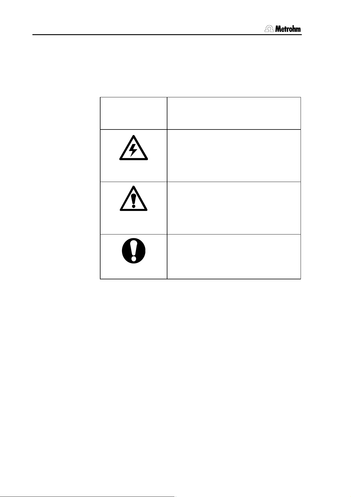
The following notations and pictograms are used in these instructions:
35
Operating element
The operating elements are explained on
pages 3ff.
Danger
This symbol indicates a possible risk of
death or injury to the user and possible
damage to the instrument or its components by electricity.
Danger/Warning
This symbol indicates a possible risk of
death or injury to the user and possible
damage to the instrument or its components.
Attention
This symbol indicates important information. Read the information provided before
you continue.
2 832 KF Thermoprep, Introduction
Page 7
1.3 Parts and controls
1.3 Parts and controls
1.3.1 Individual parts and standard accessories
1
2
3
11
5
6
8
9
10
4
7
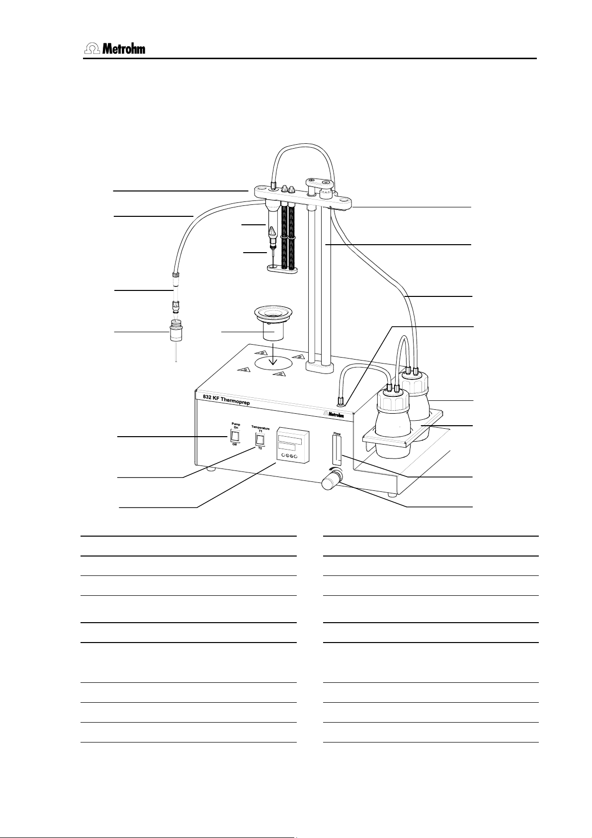
Fig. 1 Front view
12
13
14
15
16
17
18
Guide head
1
Transfer tubing 6.1805.460
2
Spacer 4.832.4190
3
Penetration and outlet needle
4
6.2816.070 and 6.2816.080
Dosing tip 6.1543.060
5
Septum stopper 6.2730.050
6
Sample holder
7
Pump switch
8
Temperature selection switch
9
832 KF Thermoprep, Introduction 3
10
11
12
13
14
15
16
17
18
Temperature controller
Clamping lever
Guide rod
Inlet tubing 6.1805.020
Air/Nitrogen outlet
Drying bottles 6.1608.050
With 6.1602.140 inset, filled with
6.2811.000 molecular sieve
Bottle holder
Flow indicator
Flow controller
Page 8
1.3 Parts and controls
1.3.2 Rear view
19
20
21
22
23
WARNING - Fire Hazard -
for conti nued pro tection replac e only
with the same ty pe and rating of fuse
100 - 120 V: 4 A (T)
220 - 240 V: 2 A (T)
f = 50/60 Hz
S = 350 VA
Inlet filt er
Key lock
On
Off
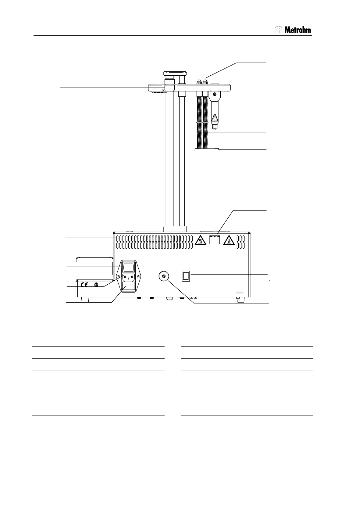
Fig. 2 Rear view
Vorsicht: Heisse Gehäuseteile
(üb er 60° C)
Attention: Hot parts
(a bove 6 0°C)
Cuidado: Partes calientes
(mas de 60°C)
Attention: Parties chaudes
(p lus de 60°C)
Type 1.832.0010 Nr.
Made by Metrohm Switzerland
0010/01104
24
25
26
27
28
29
30
Tubing guide
19
Ventilation slots
20
Mains switch
21
Mains connection
22
Fuse holder
23
Adjustment nuts
24
25
26
27
28
29
30
Transfer tubing connection
Guide spring
Needle base
Hot air outlet
Key lock switch
Air/nitrogen outlet
Connection for dust filter (6.2724.010)
4 832 KF Thermoprep, Introduction
Page 9
1.3 Parts and controls
1.3.3 Temperature controller
31
32
33
34
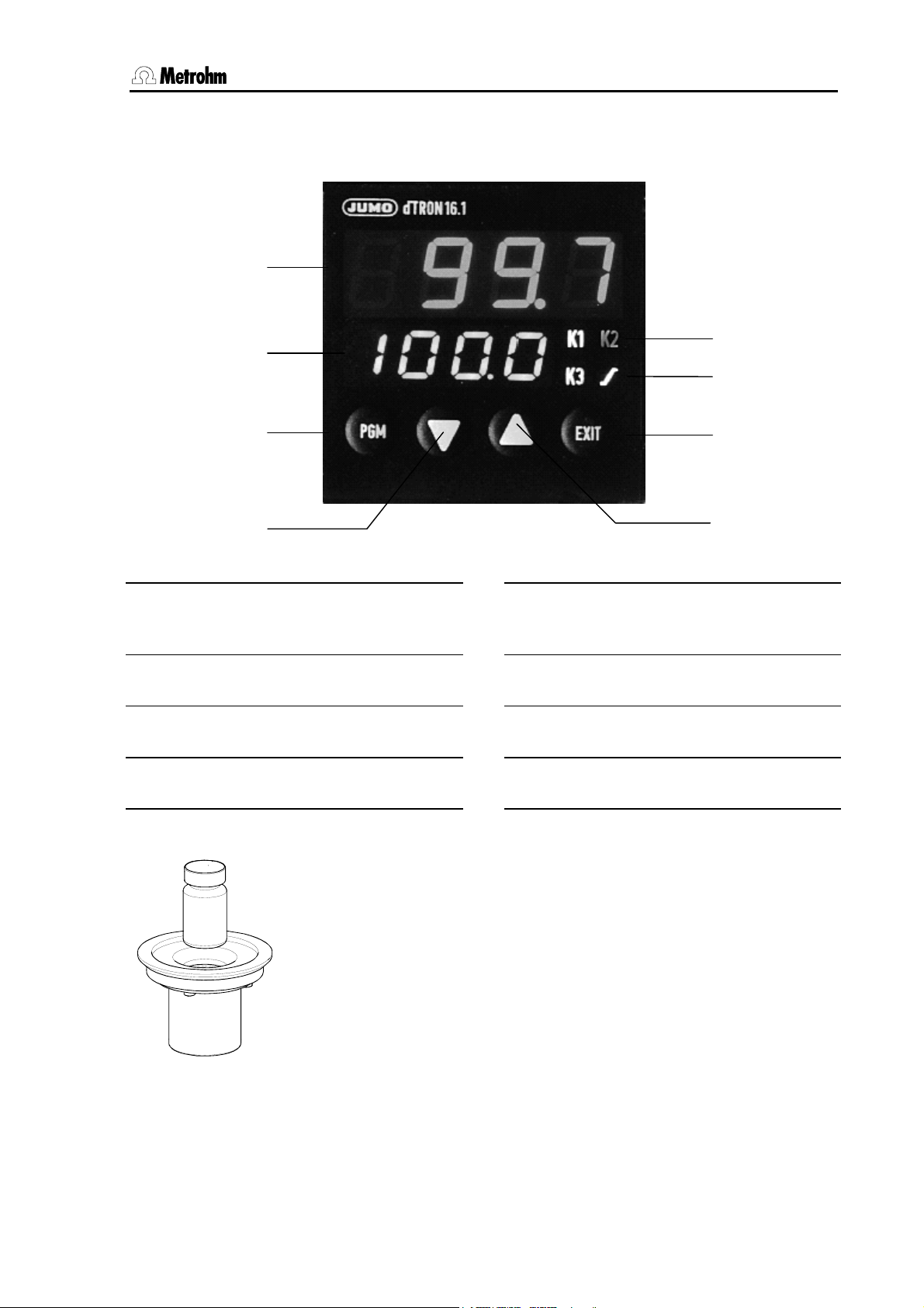
Actual value display
31
red, 4-place
Set value display
32
green, 4-place
Program key
33
for selecting the parameters
Decrement key
34
for changing values
Fig. 3 Temperature controller
35
36
37
38
Output status display
yellow, for outputs 1 to 3
(K1 and K3: oven heating, K2: fan)
LED for ramp/program function
green, lights if configured
EXIT key
to exit the dialog levels
Increment key
for changing values
35
36
37
38
1.3.4 Sample holder for standard vials
The dimensions of the 6.2063.000 sample holder are optimized for the
Metrohm 6.2419.007 standard sample vials (6 mL). This ensures the
highest possible heat flow from the oven to the sample.
If other sample containers with different dimensions shall be used
custom made sample holders can be delivered. For this the precise
dimensions (incl. dimensional tolerances) must be known.
The measures of non-standard sample containers must vary within the
following dimensional limits:
Diameter 10.0 … 32.0 mm
Fig. 4 Sample holder
832 KF Thermoprep, Introduction 5
Depth of immersion 20.0 … 45.0 mm
Page 10
2.1 General
2 Safety information
Warning!
This instrument should only be used in accordance with the information
given in these Instructions for Use.
2.1 General
This instrument left our works in perfect condition from the point of view
of its operational safety (see Technical data, safety specification). To
keep it in this condition and to continue to operate safely the following
information must be carefully observed.
2.2 Electrical safety
Please observe the following guidelines:
• Only qualified Metrohm personnel should carry out service work on
electronic components.
• Do not open the instrument housing as this could damage the instrument. The housing contains no components which could be
serviced or exchanged by the user.
Electrical safety when handling the instrument is guaranteed within the
scope of Standard IEC 61010. However, please observe the following
point:
Protection against electrostatic charges
Warning!
Electronic components are sensitive to electrostatic charges and can
be destroyed by a discharge. Always remove the mains connection
cable from socket 12 before making or breaking electrical connections
on the rear panel of the instrument.
Connection to the electricity supply:
This instrument must only be operated at the specified mains voltage.
Repair and maintenance:
If faults or malfunctions occur while using the 832 KF Thermoprep we
recommended that you first check that the connection to the control instrument has been made correctly.
The instrument must not be opened. This is reserved exclusively for
authorized service personnel.
6 832 KF Thermoprep, Safety information
Page 11
2.2 Electrical safety
3 Installation
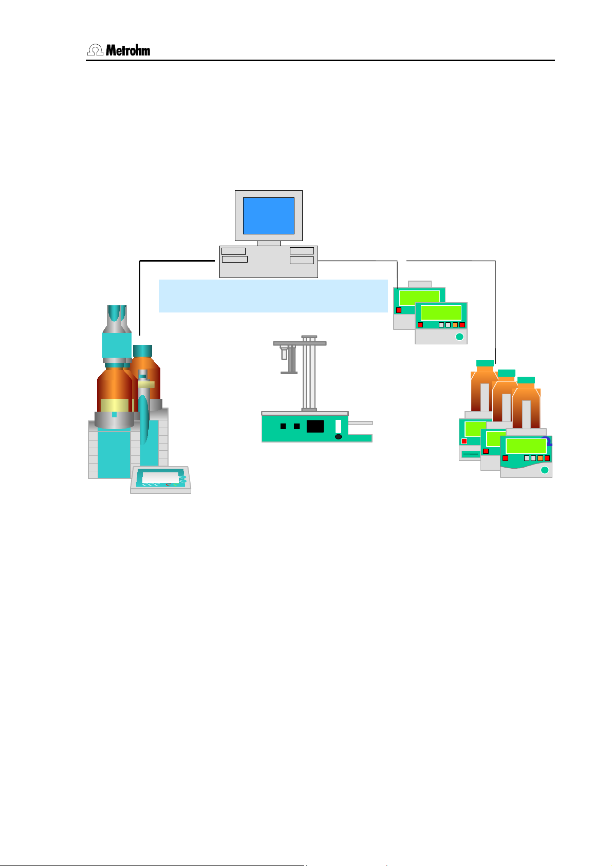
This section describes the things you should pay attention to when unpacking and starting up the 832 KF Thermoprep. It also tells you how a
complete automation system is built up.
The following illustration provides an overview of the peripheral devices
which can be used with an 832 KF Thermoprep:
PC
PC
800
800
800
800
800
800
800
800
Dosino
Dosino
Dosino
Dosino
Dosino
Dosino
Dosino
Dosino
Titriermittel
KF
Titriermittel
KF
Titriermittel
Titriermittel
KF
KF
835
835
835
Titrando
Titrando
Titrando
836
836
836
Titrando
Titrando
Titrando
Titrandos
USB
PC Control tiamo
KF
KFKF
Touch ControlTouch Control
Fig. 5: 832 KF Thermoprep – peripheral devices
LPT 1
LPT 1
USB
PC Software
COM 1
COM 1
COM 2
COM 2
USB
RS232
Tinet 2.x / VESUV 3.0
832 TP832 TP
832 Thermoprep
RS232
756 KF756 KF
831 KF831 KF
KF Coulometer
831 / 756
Titrierm ittelTitrierm ittel
Titrierm ittelTitrierm ittel
Titrierm ittel
Titrierm ittel
KFD 758
KFD 758
KFP 785
KFP 785
KFP 795KFP 795
KF Titrino
795 / 787 / 758
832 KF Thermoprep, Installation 7
Page 12

3.1 Instrument setup
3.1 Instrument setup
3.1.1 Packaging
The 832 KF Thermoprep and its specially packed accessories are supplied in very protective special packaging. Please store this packaging
in a safe place; it is the only way in which the safe transport of the instrument can be guaranteed.
3.1.2 Checks
Please check that the delivery is complete and undamaged immediately on receipt (compare with delivery note and list of accessories
given in Section 8.28.2). If transport damage is evident please refer to
the information given in Section 8.4.1 “Warranty”.
3.1.3 Location
The 832 KF Thermoprep has been developed for use indoors and must
not be used in explosion-endangered surroundings.
Place the instrument on a suitable vibration-free laboratory bench, protected as much as possible from corrosive atmospheres and contamination by chemicals.
Select a location in which the ambient temperature is normally between
+5 °C and +45 °C. The instrument should be protected against excessive variations in temperature and direct sunshine.
If an instrument which has been stored under cold conditions is
brought into a warm room then the atmospheric humidity may condense inside the instrument and form water. In order to avoid damaging
the instrument please wait for at least one hour before switching it on.
3.2 Mains connection
Please observe the following rules when connecting the instrument to
the electricity supply. If the instrument is operated with an incorrectly set
mains voltage and/or an incorrect mains fuse then it represents a fire
hazard!
Setting the mains voltage
Before you switch on the 832 KF Thermoprep for the first time please
check that the mains voltage set on the instrument (see illustration on
the following page) corresponds to your local mains voltage. If this is
not the case then you must alter the mains voltage as follows:
8 832 KF Thermoprep, Installation
Page 13

3.2 Mains connection
• Pull out mains cable
Remove the mains cable from the mains supply connection of the 832
KF Thermoprep.
• Remove the fuse holder
Use a screwdriver to loosen the fuse holder beside the mains supply
connection and remove it completely.
• Check the fuse and replace it
Carefully remove the built-in fuse for the intended voltage from the fuse
holder and check its specifications (the position of the fuse in the fuse
holder is indicated by the white arrow beside the voltage range):
100…120 V 4 A (slow blow) Metrohm-No. U.600.0022
220…240 V 2 A (slow blow) Metrohm No. U.600.0019
• Insert fuse
Exchange the fuse if necessary and replace it in the fuse holder.
• Insert fuse holder
Depending on the required mains voltage, insert the fuse holder so that
the white arrow of the corresponding voltage range points to the white
bar; this is to the right of the fuse holder (see below).
220 – 240 V 100 – 120 V
Mains switch
Mains connection
Fuse holder
100 - 120 V
220 - 240 V
Fig. 6 Fuse holder
220 - 240 V
100 - 120 V
832 KF Thermoprep, Installation 9
Page 14

3.3 Assembling the 832 KF Thermoprep
3.3 Assembling the 832 KF Thermoprep
3.3.1 Assembling the needles
41
3
39
• Screw spacer 3 (4.832.4190, L=58 mm) into distributor 39. For special
requirements, e.g. different sample vials, custom-made spacers can
be supplied, see p. 27.
• Place PTFE distance ring 41 (supplied with the needle) on penetration
needle 42 (6.2816.070) and insert this into distributor 39 from above
(see left). Pull penetration needle 42 down as far as it will go.
• Slide hollow outlet needle 43 over penetration needle 42 from below
and fasten it to Luer-lock connector of the spacer 3.
• Connect inlet tubing 13 (6.1805.020, 52 cm) to distributor 39 from
above and fasten it. This fixes penetration needle 42 in the proper
position.
44
13
Fig. 7
Needle assembly
43
12
42
27
Fig. 8 Guide head with needles
To prevent possible injury the height of needle base 27, which protects
the tip of penetration needle 42, can be adjusted. Screw adjustment
nuts 44 of guide rod 12 until the needle tip is flush with the lower side of
needle base 27.
10 832 KF Thermoprep, Installation
Page 15

3.3 Assembling the 832 KF Thermoprep
3.3.2 Attaching the drying bottles
1. Fill 6.1608.050 drying bottles 15 with 6.2811.000 molecular sieve
and place 6.1821.040 outlet tube (with 6.2821.090 filter) in
6.1602.140 screw cap. Screw the screw caps onto the drying bottles.
14
16
When attaching the tubing please
observe the following:
To filter the carrier gas before leaving
the drying bottle, it must be led
through the outlet tube to the outlet
connection.
2. Place drying bottles 15 in holder 16 of the
oven. Screw the 6.1805.180 Tubing (16 cm) to
the inlet tubing connection of the front drying
bottle. The carrier gas must enter the drying
15
bottle at the top of the bottle. Connect the other
end of the tubing to the air/nitrogen outlet 14
(see drawing).
3. The rear drying bottle is connected to the front
bottle using 6.1805.010 Tubing (13 cm). Screw
the tubing onto the outlet tube of the front bottle
and connect the other end to the inlet connection of the rear drying bottle. The carrier gas
must enter the rear drying bottle at the top of
the bottle.
4. Screw 6.1805.020 Tubing (52 cm) onto the
outlet tube of the rear drying bottle and lead it
through the tubing guide on the guide head of
the 832 KF Thermoprep. The free end of the
tubing is screwed onto the connection provided
for it on the guide head.
5. 6.1805.460 Transfer tubing (27 cm) is screwed onto the back of the
distributor piece. Attach 6.1543.060 Dosing tip to the other end of
the tubing and insert it into the titration vessel.
3.3.3 Attaching the dust filter
Attach 6.2724.010 Dust filter to the 'Inlet filter' connection on the rear
panel of the instrument.
If nitrogen is to be used as the carrier gas then the nitrogen inlet tubing
can be attached directly to the dust filter tubing nozzle.
832 KF Thermoprep, Installation 11
Page 16

3.4 Assembling the coulometric cell
3.4 Assembling the coulometric cell
Generator electrode
Fig. 9 Coulometer cell
with drying tube
Indicator electrode
6.1543.060 Tip
Screw nipple of
6.2730.030
6.1446.060 Stopper
The coulometer cell is setup for the gas inlet as
follows:
6.1543.060 Tip is screwed into the 6.1446.060 Stopper
by using the screw nipple (screw nipple of 6.2730.030
with O-ring) and the stopper is inserted into the SGJ
14/15 opening.
If simultaneous aspiration is necessary while gas is
being led in then the gas inlet tubing must be inserted
into the side inlet. This requires the use of the following
parts:
Tip 6.1543.060
Screw cap 6.2701.0
40
Sealing ring A.254.0104
A titration vessel with 2 side-mounted inlets is also
available: order number 6.1465.320.
3.5 Assembling the titration vessel for volumetric KF titrators
The titration vessel is adapted for the gas inlet in the
following way:
Instead of the 6.2730.020 Septum stopper, the
6.2730.050 Stopper is used with 6.1543.060 Tip. (Nipple
and O-ring of 6.2730.030 from the Titrino accessories.)
Fig. 10 Volumetric KF cell
12 832 KF Thermoprep, Installation
Page 17

4.1 Inserting and removing sample vials
4 Operation
This section describes the basic principles of handling the 832 KF Thermoprep.
4.1 Inserting and removing sample vials
As the oven of the 832 KF Thermoprep can reach a temperature of
250 °C, vials must only be inserted in or removed from the oven by using crimping pliers or other tools. Hot vials should only be placed on
temperature-resistant surfaces.
Fig. 11 Crimping pliers
4.2 Needle penetration
Always lower guide head 1 by using both hands. In this way you can
avoid injuring yourself on the needle.
Fig. 12 Loosening the guide head
Clamping lever
11
832 KF Thermoprep, Operation 13
Page 18

4.3 The pump
Loosen the red clamping lever by pressing it strongly and lower the
guide head and needle by using both hands. Penetrate the vial septum
with the needle and lower the guide head until it reaches the bottom
stop.
4.3 The pump
The 832 KF Thermoprep is equipped with a powerful air pump, with
which the released humidity of the sample can be transferred to a titration cell in a constant carrier gas stream.
Atach a 6.2724.010 dust filter to the air inlet 30 on the instrument's rear
side. Avoid the intrusion of dust particles.
The dust filter must be replaced in a regular equipment service.
If thermal unstable samples, which may decompose at higher temperatures are treated, the use of nitrogen as carrier gas is highly recommended. Connect the nitrogen supply pipe to the hose olive of the dust
filter. The maximum pressure of the nitrogen supply must not exceed
1 bar.
Fig. 13 Needle in lowered position
14 832 KF Thermoprep, Operation
Page 19

4.4 The temperature controller
4.4 The temperature controller
The best proven dTron 16.1 (JUMO) temperature controller of the 832
KF Thermoprep is very easy to use for routine operation of the instrument. Fine adjustment of the control parameters is possible but not
normally necessary. Unappropriate parameters of configuration settings
may cause faults of the instrument. The default settings can be used
without any problems. The temperature controller 10 also has a comfortable and simple self-optimization function which can be used if necessary.
4.4.1 Two set temperatures
The temperature controller of the 832 KF Thermoprep can store two set temperatures (T1 and T2).
You can switch between these two set temperatures by using the temperature selection switch.
The oven starts to heat up as soon as the instrument is switched on
and is controlled at the set temperature (T1 or T2). If a switch is made
from one set temperature to the other one then this will be adopted immediately by the temperature controller, i.e. the oven will immediately
heat up or cool down until the set temperature has been reached.
4.4.2 Setting a temperature
The desired temperature (T1 or T2) is easily set by using the two arrow
keys (increment key 38) and (decrement key 34) of the temperature controller. The set temperature can be altered at any time, regardless of whether the set temperature has been reached or not.
Please observe the green set value display 32. This always refers to the
set temperature T1 or T2 which has been selected. Longer pressure on
an arrow key changes the set value more quickly.
Altered set values are immediately accepted by the temperature controller.
If the key lock function (tumbler switch 29 on the rear panel of the housing) is switched on then no settings can be made.
Temperature display
The display indicates the real value and the set
value (T1 or T2).
832 KF Thermoprep, Operation 15
Page 20

4.4 The temperature controller
4.4.3 Self-optimization of the control parameters
Self-optimization should only be used when the set temperature cannot
be achieved by the temperature controller or when the actual temperature varies about the set temperature by more than 2…5 °C (overshooting).
Preparation
Set the same conditions as would be used in a real determination.
• Set the temperature (T1 or T2) to a value corresponding to a real
determination (e.g. 120 °C).
• Wait until the oven has reached the set temperature.
• Insert a sealed sample vial containing a sample in the oven.
• Lower the work head and completely penetrate the sample vial sep-
tum with the needle.
• Switch on the pump (or open the nitrogen valve) and set the gas
flow to a realistic value which would be used during a proper determination.
Self-optimization
• Start the self-optimization process with EXIT (keep key 37 pressed
down for at least 2s!).
During the self-optimization process "tunE" blinks in the display 31.
When the blinking stops the process is finished. Self-optimization normally takes 1 to 5 minutes. The duration depends on the selected temperature, i.e. the higher the temperature the shorter it takes.
•
• Save the control parameters which have been determined by press-
ing the EXIT key 37 for 2 seconds.
The self-optimization process can be canceled by pressing the EXIT
key 37 briefly.
4.4.4 Key lock function
The temperature controller settings can be protected against accidental
alteration. On the rear panel of the 832 KF Thermoprep the 'Key Lock'
tumbler switch 29 can be switched to 'On'.
If the key lock function is switched on the 'Temperature' tumbler switch
9 can still be used to select the two set temperatures T1 and T2. It is
also possible to switch the pump on and off (key 8).
However, no alteration can be made to the temperature controller 10
with the key lock function switched on.
16 832 KF Thermoprep, Operation
Page 21

4.5 Working procedure
4.5 Working procedure
Warning!
As both the sample vials and the oven become very hot the sample
vials must be removed from the oven by using the crimping pliers. The
sample vials should only be placed on a heat-resistant surface.
In principle two different methods can be used.
For samples with a low water content one (or more) blank values
must be determined and subtracted from the water content determined
for the sample. Sample vials contain a considerable amount of atmospheric humidity, e.g. Metrohm standard vials with a volume of 6 mL can
contain 60…150 µg water. While the determination is being carried out
atmospheric moisture can also enter the coulometer cell as a result of
leaks, etc.
For samples with a high water content blank value determinations
are not necessary as the atmospheric humidity contained in the vial is
negligible when compared with the moisture contained in the sample. If
no blank determinations are carried out then the whole procedure is
simplified and takes less time.
Determinations with the 832 KF Thermoprep basically take part in three
phases:
1. Preparing / Conditioning the system
2. Possibly determining the blank value
3. Determination of the sample
The procedure for determinations with the 756/831 Coulometer is described below. A similar procedure can be used with a volumetric KF titrator (e.g. 795 KFT Titrino).
Note
When using either a coulometer or a volumetric KF titrator it is absolutely essential that an extraction time of at least 300 s is observed per
determination. More details are given in the Instructions for Use of the
particular instrument.
832 KF Thermoprep, Operation 17
Page 22

4.5 Working procedure
4.5.1 Preparing the 832 KF Thermoprep/756/831 Coulometer system
1. Switch on the 832 KF Thermoprep. The oven heats up automatically to set temperature T1 or T2.
2. If necessary use the set value switch to alter set temperature T1 or
T2.
3. Place an empty sealed vial in the oven.
4. Lower the needle until the stop is reached. Both hands should be
used for safety reasons.
5. Switch on air pump (if N
is used open the nitrogen valve).
2
6. Check the gas flow at the flowmeter 17 and alter it if necessary
(optimal range: 40…60 mL/min).
7. Start the 756/831 Coulometer and allow it to be conditioned.
8. Let the oven heat up until the set temperature is reached and the
coulometer cell is conditioned.
4.5.2 Determination with blank value subtraction
Determination of blank value(s)
1. Load a method for a blank value determination (e.g. Blank) into the
coulometer. The mean value of the blank value determinations
should be stored as a common variable. Set the extraction time to
300 s.
2. Start conditioning the coulometer (with the <START> key).
3. Wait until the set temperature has been reached and the coulometer cell is conditioned.
4. Start the blank determination at the coulometer with <START>.
5. Raise the needle fully and remove the conditioning vial from the
oven with the crimping pliers.
6. Insert an empty sealed vial (blank sample) in the oven using the
crimping pliers.
7. Lower the needle until it reaches the stop and pierce the septum
cap.
8. After the determination wait for post-conditioning to be completed
and, if necessary, carry out further blank value determinations, i.e.
repeat the procedure from item 3 onward.
Sample determination
1. Load a method for a sample determination into the coulometer.
The mean blank value, stored as a common variable, is to be subtracted from the sample result. Set the extraction time to 300 s.
2. Start conditioning the coulometer (with the <START> key).
3. Wait until the set temperature has been reached and the coulometer cell is conditioned.
4. Start the determination at the coulometer with <START>.
18 832 KF Thermoprep, Operation
Page 23

4.5 Working procedure
5. Raise the needle fully and remove the blank sample vial from the
oven with the crimping pliers.
6. Insert the sealed sample vial in the oven using the crimping pliers.
7. Lower the needle until it reaches the stop. Enter the sample size at
the coulometer and confirm it with <ENTER>.
8. After the determination wait for post-conditioning to be completed
and, if necessary, carry out further determinations.
4.5.3 Determination without blank value subtraction
Sample determination
1. Load a method for a sample determination into the coulometer. The
result calculation must not contain any blank value subtraction. Set
the extraction time to 300 s. 'Value' must be entered under
'>Preselection' | 'Request sample size'.
2. Start conditioning the coulometer (with the <START> key).
3. Wait until the set temperature has been reached and the coulometer
cell is conditioned.
4. Start the determination at the coulometer with the <START> key.
5. Raise the needle fully and remove the conditioning vial from the
oven with the crimping pliers.
6. Insert the sealed sample vial) in the oven using the crimping pliers.
7. Lower the needle until it reaches the stop. Enter the sample size at
the coulometer and confirm it with <ENTER>.
8. After the determination wait for post-conditioning to be completed
and, if necessary, carry out further determinations.
832 KF Thermoprep, Operation 19
Page 24

4.6 Practical information
4.6 Practical information
Selecting the carrier gas
Nitrogen (N
sitive to air or oxygen (decomposition) or releases substances which interfere with the KF reaction.
Temperature setting
Select as high a temperature as the sample allows (high temperature =
short analysis time). However, the sample must not decompose. It
should not release any other oxidizable substances than water. The
temperature shown on the temperature controller refers to the temperature in the aluminum heating block and not to the sample temperature.
Depending on the size of vial used and the temperature setting, the
sample temperature could vary by up to 10%.
Gas flow
The gas flow is set on the flow controller on the front panel of the 832
KF Thermoprep and passes through the drying bottles. The gas flow
should be kept as low as possible. With very moist samples in particular
care must be taken that large amounts of water do not enter the titration
vessel too quickly. The solution in cell must be able to absorb the
driven-off moisture. A flow rate of 40…60 mL/min is normally optimal.
If the needle is inserted in the sample bottle until the stop is reached
then the flow of gas through the sample will be transferred to the titration vessel via the outlet needle. The moisture is then titrated in the titration vessel.
Extraction time
An extraction time of at least 5 min should be set on the connected titrator, in order to prevent the titration from being stopped before all the
sample has released all its moisture.
Conditioning the system
Before a measurement the system must be conditioned with an empty
sealed sample vial (conditioning vessel).
Literature
• Hydranal
de Haën, 1987
• The following Metrohm Application Bulletins can be obtained free of
charge:
should be used as the carrier gas if the hot sample is sen-
2)
®
Manual, Water reagents for Karl-Fischer-Titration, Riedel-
No. 109 Karl Fischer water determination with the KF drying
oven
No. 145 Determination of low water contents in plastics using
the KF oven method
No. 217 Karl Fischer water determination in pharmaceuticals using the oven method
20 832 KF Thermoprep, Operation
Page 25

4.6 Practical information
5 Maintenance information
The 832 KF Thermoprep does not need a lot of care. Ensure that it does
not become excessively dirty and is not exposed to corrosive atmospheres.
• Renew used-up molecular sieve in good time. The molecular sieve
should be exchanged as soon as increased drift values occur in the
Karl Fischer cell.
• Rinse the tubing and the distributor occasionally and carefully dry
the tubing.
• Clean the oven compartment at regular intervals.
• Replace the dust filter on the rear panel when necessary.
6 GLP validation
Each instrument produced by Metrohm undergoes a rigorous quality
control check before delivery.
GLP (Good Laboratory Practice) requires, among other things, that the
precision and correctness of analytical instruments are checked at
regular intervals by using SOPs (Standard Operating Procedure).
Recommended literature
• Metrohm leaflets "Quality Management with Metrohm", detailed information about the principles and procedures of Good Laboratory
Practice
• Metrohm Application Bulletin 252/1 "Validation of Metrohm titrators
according to GLP/ISO 9001"
832 KF Thermoprep, Maintenance information 21
Page 26

7.1 Problems
s
s
7 Troubleshooting
7.1 Problems
Problem Possible cause Remedy
Titration results
widely scattered.
Drift too high.
Titration time too
long.
Molecular sieve in the
drying bottles is used
up.
Condensate in the outlet
tubing.
Gas flow too high. Reduce gas flow
Inhomogeneous
sample.
Not all the moisture has
been driven out.
Leaky tubing connections.
Molecular sieve in the
drying bottles is used
up.
Leaky titration vessel Orings.
Leaky septum cap. Replace septum cap.
Inhomogeneous
sample.
Replace molecular sieve. (If the
molecular sieve in the front bottle is
till OK then this bottle can be used
as the rear bottle. The "freshest“ molecular sieve belongs in the front bottle.)
Dry the tubing. Reduce gas flow.
Possibly lower the temperature.
Reduce sample particle size before
weighing.
Set "harder" switch-off conditions at
the titrator: Lower stop drift, increased
switch-off delay.
Check tubing and replace if neces-
sary.
Replace molecular sieve. (If the
molecular sieve in the front bottle is
till OK then this bottle can be used
as the rear bottle. The "freshest“ molecular sieve belongs in the front bottle.)
Replace O-rings.
Reduce sample particle size before
weighing.
22 832 KF Thermoprep, Troubleshooting
Page 27

8.1 Technical data
8 Annex
In this section you will find the most important technical data of the 832
KF Thermoprep, a list of standard and optional accessories and the
warranty and conformity declarations.
8.1 Technical data
8.1.1 Oven
Temperature range
Correction range
Heating power
Heating rate
50…250 °C
-10…+10 °C
200 VA
15 °C/min
8.1.2 Air pump
Delivery rate
Adjustment range
0…300 mL/min (0…18 L/h)
0…80 mL/min (0…4.8 L/h)
8.1.3 Temperature controller
Make
Temperature control
Display
JUMO dTRON 16.1
Self-optimizing microprocessor controller, can be used as
2-point, 3-point or continuous controller
2x 7-segment digital display of set and actual values
8.1.4 Power supply
Voltage
Frequency
Power consumption
100...120 V, 220...240 V
50...60 Hz
220 VA
8.1.5 Safety specifications
Construction and testing According to IEC 61010, EN 61010, EN50093, protection
class 3
Safety information The Instructions for Use contains safety information that
must be observed by the user in order to ensure the safe
operation of the instrument.
832 KF Thermoprep, Annex 23
Page 28

8.1 Technical data
8.1.6 Electromagnetic compatibility (EMC)
Emission Standards fulfilled:
- EN/IEC 61326-1
- EN 55022 class B
- CISPR 22 class B
- EN/IEC 61000-3-2 class A
- EN/IEC 61000-3-3
- Namur
Immunity Standards fulfilled:
- EN/IEC 61326-1
- EN/IEC 61000-4-2
- EN/IEC 61000-4-3
- EN/IEC 61000-4-4
- EN/IEC 61000-4-5
- EN/IEC 61000-4-6
- EN/IEC 61000-4-8
- EN/IEC 61000-4-11
- Namur
8.1.7 Ambient temperature
Nominal working range
Storage
Transport
+5…+45 °C
(at max. 85% relative humidity)
-20 °C…+60 °C
-40 °C…+60 °C
8.1.8 Dimensions and materials
Height
Width
Depth
Weight approx. 8.9 kg (without accessories)
Housing material Metal housing, surface-refined
49.5 cm
35.5 cm
22.0 cm
24 832 KF Thermoprep, Annex
Page 29

8.2 Standard equipment
8.2 Standard equipment
Immediately upon receipt of the instrument please check that the delivery is complete.
8.2.1 832 KF Thermoprep
Order no. 2.832.0020
No. Order no. Description
1 1.832.0020 832 KF Thermoprep
KF oven for processing single samples in sealed vials.
The following accessories are supplied as standard:
1 6.1543.060 ETFE/FEP dosing tip
2 6.1602.145 Drying bottle insert
2 6.1608.050 Clear glass bottle GL 45, 100 mL
1 6.1805.010 FEP tubing, M6, L=13 cm
1 6.1805.020 FEP tubing, M6, L=52 cm
1 6.1805.180 FEP tubing, M6, L=16 cm
1 6.1805.460 FEP tubing, M6, L=27 cm
832 KF Thermoprep, Annex 25
Page 30

8.2 Standard equipment
2 6.1821.040 Inlet tube for drying bottle, with filter,
L=92 mm
1 6.2049.030 Spacer with Luer-Lock needle
connector, L=58mm
1 6.2063.000 Sample holder for 6.2419.007
sample vials (6 mL)
1 6.2621.110 Crimping pliers
1 6.2724.010 Dust filter, 32 mm diameter
1 6.2730.050 Stopper for dosing tip, M10, with
O-ring
1 6.2739.000 Tubing nipple wrench
1 6.2811.000 Molecular sieve, 250 g
1 6.2816.070 Penetration needle
1 6.2816.080 Outlet needle
100 6.2419.007 Sample vials, 6 mL
100 6.1448.057 Septum seals for sample vial 6.2419.007
1 8.800.1023 Instructions for Use for 832 KF Thermoprep
26 832 KF Thermoprep, Annex
Page 31

8.3 Optional accessories
8.3 Optional accessories
8.3.1 Sample vials
Order no. Description
6.2419.000 Sample vials , 6 mL, 1000 ea.
6.1448.050 Septum seals for sample vial, 1000 ea.
In order to use other sample vials with different dimensions the sample
holder of the 832 KF Thermoprep must be replaced. Please contact
your Metrohm distributor.
For further accessories please see Metrohm Accessories Catalog.
832 KF Thermoprep, Annex 27
Page 32

8.4 Warranty and conformity
8.4 Warranty and conformity
8.4.1 Warranty
The warranty on our products is limited to defects that are traceable to
material, construction or manufacturing error which occur within 12
months from the day of delivery. In this case, the defects will be rectified in our workshops free of charge. Transport costs are to be paid by
the customer.
For day and night operation, the warranty is limited to 6 months.
Glass breakage in the case of electrodes or other parts is not covered
by the warranty. Checks which are not a result of material or manufacturing faults are also charged during the warranty period. For parts of
outside manufacture insofar as these constitute an appreciable part of
our instrument, the warranty stipulations of the manufacturer in question
apply.
With the regard to the guarantee of accuracy, the technical specifications in the instruction manual are authoritative.
Concerning defects in material, construction or design as well as the
absence of guaranteed features, the orderer has no rights or claims except those mentioned above.
If damage of the packaging is evident on receipt of a consignment or if
the goods show signs of transport damage after unpacking, the carrier
must be informed immediately and a written damage report demanded.
lack of an official damage report releases Metrohm from any liability to
pay compensation.
If any instruments and parts have to be returned, the original packaging
should be used if at all possible. This applies above all to instruments,
electrodes, burette cylinders and PTFE pistons. Before embedment in
wood shavings or similar material, the parts must be packed in a dustproof package (for instruments, use of a plastic bag is imperative). If
open assemblies are enclosed in the scope of delivery that are sensitive to electromagnetic voltages (e.g. data interfaces etc.) these must
be returned in the associated original protective packaging (e.g. conductive protective bag). (Exception: assemblies with built-in voltage
source belong in a non-conductive protective packaging).
No warranty responsibility whatsoever will be accepted by Metrohm for
damage which arises as a result of non-compliance with these instructions.
28 832 KF Thermoprep, Annex
Page 33

8.4 Warranty and conformity
8.4.2 EU Declaration of Conformity for 832 KF Thermoprep
EU Declaration of Conformity
The Metrohm Ltd. company, Herisau, Switzerland hereby certifies, that the instrument:
832 KF Thermoprep
meets the requirements of EU Directives 89/336/EEC and 73/23/EEC.
Source of specifications:
EN 61326-1 Electromagnetic compatibility, basic specification Emitted In-
terference, Interference Immunity
EN 61010-1 Safety requirements for electrical laboratory measurement
and control equipment
Description of the instrument:
Instrument with sample heating block, temperature controller and air pump for
processing samples according to the Karl Fischer oven method.
Herisau, May 30, 2002
Dr. J. Frank Ch. Buchmann
Development Manager Production and
Quality Assurance Manager
832 KF Thermoprep, Annex 29
Page 34

8.4 Warranty and conformity
8.4.3 Declaration of Conformity
Certificate of Conformity and System Validation
This is to certify the conformity to the standard specifications for electrical appliances
and accessories, as well as to the standard specifications for security and to system
validation issued by the manufacturing company.
Name of commodity: 832 KF Thermoprep
Manufacturer: Metrohm Ltd., Herisau, Switzerland
Technical specifications: Distribution voltage:
100…120, 220…240 V
Frequency: 50…60 Hz
The instrument was manufactured and tested according to the following
standards:
Electromagnetic compatibility:
Emission
IEC 61326-1, EN 55022 class B, CISPR 22 class B EN/IEC 61000-3-2 class A,
EN/IEC 61000-3-3
Immunity
EN/IEC 61326-1, EN/IEC 61000-4-2, EN/IEC 61000-4-3, EN/IEC 61000-4-4, EN/IEC
61000-4-5, EN/IEC 61000-4-6, EN/IEC 61000-4-8, EN/IEC 61000-4-11, EN/IEC
61000-4-14
Security specifications
EN/IEC 61010-1, UL 3101-1
It has also been certified by the Swiss Electrotechnical Association (SEV), which is
member of the International Certification Body (CB/IEC).
The technical specifications are documented in the instruction manual.
Metrohm Ltd. is holder of the SQS-certificate of the quality system ISO 9001 for quality
assurance in design/development, production, installation and servicing.
Herisau, May 30, 2002
Dr. J. Frank Ch. Buchmann
Development Manager Production and
Quality Assurance Manager
30 832 KF Thermoprep, Annex
Page 35

Index
Index
<ENTER> ............................. 19
<START>........................18, 19
A
Accessories ............................26
Actual value display ..................5
Adjustment nuts..................4, 10
Air inlet ....................................14
Air outlet................................3, 4
Air pump .................................14
Ambient temperature ..........8, 24
Assembling .............................10
Atmospheric humidity...............8
B
Blank value..............................18
Bottle holder..............................3
C
Care ........................................21
Carrier gas ........................14, 20
Certificate................................30
Clamping lever....................3, 14
Cleaning..................................21
Condensation .........................22
Conformity ..............................29
Connection ...............................6
Corrosive atmospheres ..........21
Coulometric cell ......................12
Crimping pliers..................13, 17
D
Danger ......................................2
Declaration of conformity........29
Decomposition .......................20
Decrement key....................5, 15
Delivery rate ............................23
Depth of immersion ..................5
Diameter ...................................5
Dimensions...............................5
Dirty......................................... 21
Display ....................................23
Distance ring........................... 10
Distributor ...............................10
Dosing tip..................................3
Drift too high ...........................22
Drying bottle .............................3
Drying bottles..........................11
dTron 16.1 (JUMO).................15
Dust filter.................4, 11, 14, 21
E
Electrical safety.........................6
Electricity supply...................6, 8
Electromagnetic compatibility ....
.....................................24, 30
Electrostatic charges ................6
Emission ...........................24, 30
EU Declaration........................ 29
EXIT key ....................................5
Extraction time ..................17, 20
F
Faults ........................................6
Flow controller ..........................3
Flow indicator............................3
Flowmeter ...............................18
Fuse ..........................................9
Fuse holder...........................4, 9
G
Gas flow..................................20
GLP .........................................21
Good Laboratory Practice ......21
Guide head ...................3, 10, 13
Guide rod..................................3
Guide spring .............................4
H
Handling .................................13
Heating rate ............................23
High water content..................17
Hollow needle .........................10
Hot air outlet .............................4
I
Immunity ...........................24, 30
Increment key .....................5, 15
Information................................2
Inlet filter..................................11
Inlet tubing ..........................3, 10
Inserting sample vials .............13
Installation............................. 7, 8
J
JUMO...................................... 15
K
Karl Fischer.............................20
Key lock function ....................16
Key lock switch .........................4
L
Leaking ...................................22
LED ...........................................5
Literature .................................20
Location ....................................8
Low water content...................17
Luer-lock adapter....................10
M
Mains connection .................4, 8
Mains switch .............................4
Maintenance ...........................21
Malfunctions .............................6
Materials .................................24
Maximum pressure .................14
Molecular sieve.................11, 21
N
Needle assembly ....................10
Needle base..............................4
Needle penetration .................13
Needles...................................10
Nitrogen ............................14, 20
Nitrogen outlet ......................3, 4
Notations...................................2
O
Operation ................................13
Outlet needle ......................3, 10
Output status display................5
Oven .........................................3
Overshooting ..........................16
P
Packaging.................................8
Parts.......................................... 3
Penetration needle..............3, 10
Peripheral devices ....................7
Pictograms................................2
Power consumption................23
Power supply ..........................23
Practical information ...............20
Preparing ................................18
Pressure..................................14
Problems.................................22
Procedure ...............................17
Program key..............................5
Pump switch .............................3
Q
Quality control......................... 21
R
Rear view ..................................4
Relative humidity.....................24
Removing sample vials...........13
Repair........................................6
S
Safety information...............6, 23
Sample containers....................5
Sample determination.............19
Sample holder.......................3, 5
Sample vials......................26, 27
Sealing ring.............................12
Security specifications ............30
Self-optimization .....................16
Septum seals ....................26, 27
Septum stopper ........................3
Service-personnel .....................6
Set temperatures ....................15
Set value display................. 5, 15
Setup.........................................8
832 KF Thermoprep, Index 31
Page 36

Index
SOP ........................................21
Spacer ....................................10
Standard accessories............... 3
Standard equipment...............25
Standards ............................... 24
System conditioning ...............20
T
T1, T2......................................15
Technical data ........................23
Temperature controller ...3, 5, 15
Display/Control parts................5
Temperature display...............15
Temperature selection switch.....
.......................................3, 15
Temperature setting ...............20
Titration vessel........................12
Tolerances ................................ 5
Transfer tubing..........................3
Transfer tubing connection....... 4
Transport damage..................28
Troubleshooting...................... 22
Tubing guide............................. 4
V
Validation ................................ 21
Ventilation slots......................... 4
Voltage.................................. 8, 9
Volumetric KF cell...................12
W
Warning.....................................2
Warranty.................................. 28
Water content .........................17
32 832 KF Thermoprep, Index
 Loading...