

Page 1
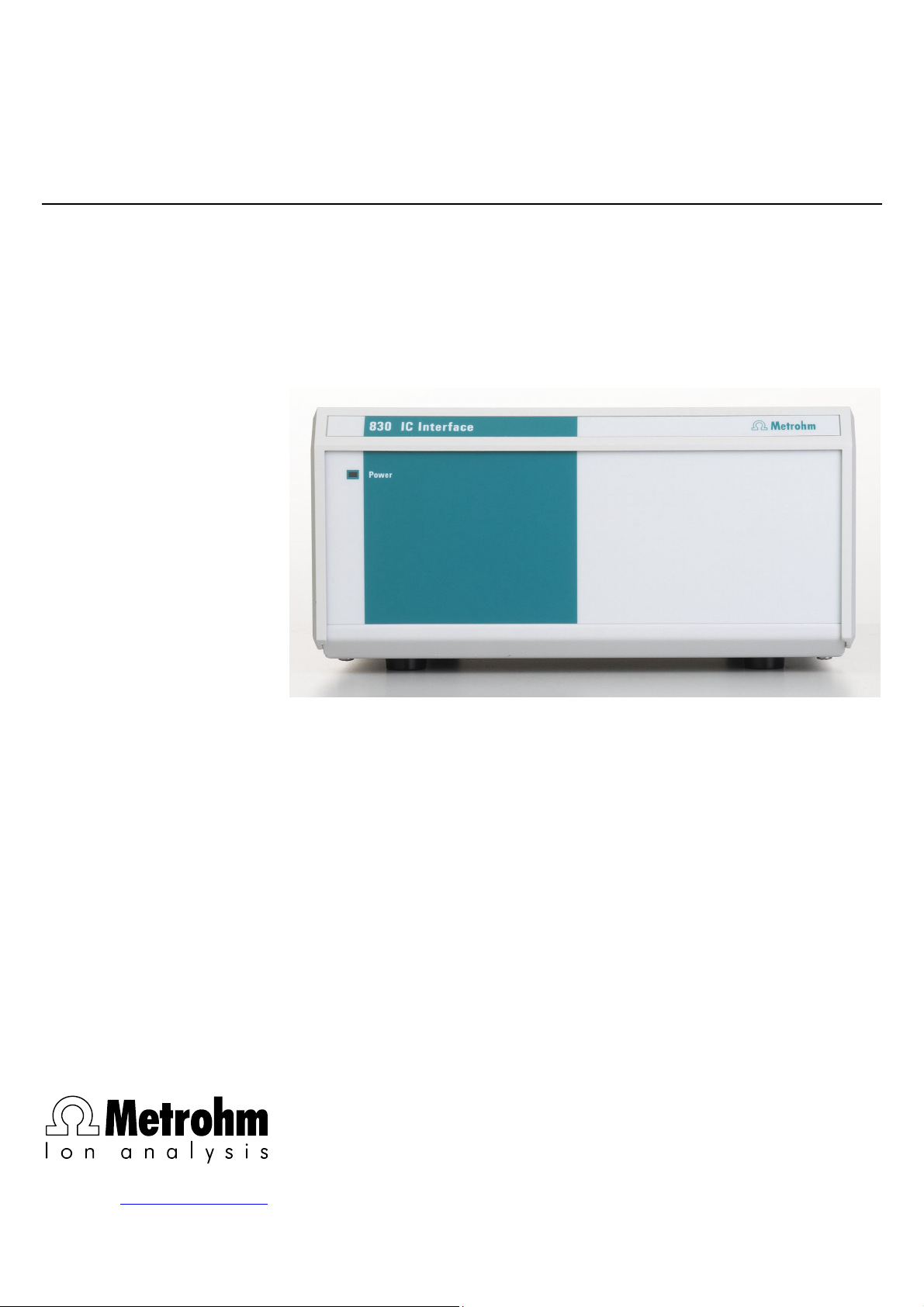
830 IC Interface
CH-9101 Herisau/Switzerland
E-Mail info@metrohm.com
Internet www.metrohm.com
Instuctions for Use
8.830.1003
Page 2

Page 3

CH-9101 Herisau/Switzerland
E-Mail info@metrohm.com
Internet www.metrohm.com
830 IC Interface
5.830.0020 Program
Instructions for Use
8.830.1003 07.2003 / pkl
Page 4

Teachware
Metrohm AG
Oberdorfstrasse 68
CH-9101 Herisau
teachware@metrohm.com
st
Edition 2003
1
These instructions are protected by copyright. All rights reserved.
Although all the information given in these instructions has been checked with great care, errors
cannot be entirely excluded. Should you notice any mistakes please inform the author at the
address given above.
Page 5

Table of contents
Table of contents
1 Introduction.................................................... 1
1.1 Instrument description ............................................................. 1
1.2 Parts and controls..................................................................... 2
1.3 Information on the Instructions for Use................................... 4
1.3.1 Organization ..................................................................................4
1.3.2 Notation and pictograms ..............................................................5
1.4 Safety notes .............................................................................. 6
2 Installation ..................................................... 7
2.1 Setting up the instrument ......................................................... 7
2.1.1 Packaging......................................................................................7
2.1.2 Check.............................................................................................7
2.1.3 Location ......................................................................................... 7
2.1.4 Arrangement of the instruments....................................................7
2.2 Mains connection...................................................................... 8
2.2.1 Mains voltage and fuses ...............................................................8
2.2.2 Mains cable ...................................................................................8
2.2.3 Switching the instrument on/off.....................................................8
2.3 Connection to the PC................................................................ 9
2.3.1 Connecting cable ..........................................................................9
2.3.2 Software installation ......................................................................9
2.4 Connection of external instruments....................................... 10
2.4.1 General information.....................................................................10
2.4.2 819 IC Detector, 820 IC Separation Center, 818 IC Pump .........12
2.4.3 833 IC Liquid Handling Pump Unit .............................................13
2.4.4 833 IC Liquid Handling Suppressor-Unit .................................... 14
2.4.5 833 IC Liquid Handling Sample Prep Unit .................................. 15
2.4.6 833 IC Liquid Handling Dialysis Unit...........................................16
2.4.7 833 IC Liquid Handling Ultra Filtration Unit.................................17
2.4.8 Triathlon Autosampler .................................................................18
2.4.9 766 IC Sample Processor ...........................................................19
2.4.10 791 IC VA Detector ......................................................................20
2.4.11 761 Compact IC ..........................................................................21
2.4.12 812 IC Valve Unit and 817 Bioscan............................................. 22
2.4.13 816 IC Eluent Selector ................................................................. 23
2.4.14 828 IC Dual Suppressor ..............................................................24
2.4.15 837 IC Combi Degasser..............................................................25
3 Operation...................................................... 26
3.1 Switch instrument on/off ........................................................ 26
3.2 Settings in the "830 IC Interface" window.............................. 27
3.2.1 Event output lines ........................................................................ 30
4 Appendix ....................................................... 34
4.1 Technical data......................................................................... 34
4.2 Scope of delivery .................................................................... 38
4.3 Optional accessories.............................................................. 39
4.4 Validation / GLP ...................................................................... 40
4.5 Warranty and Conformity ....................................................... 41
830 IC Interface / 8.830.1003 Instructions for Use
I
Page 6

Table of contents
4.5.1 Warranty ......................................................................................41
4.5.2 Declaration of Conformity ...........................................................42
4.5.3 Quality Management Principles .................................................. 43
4.6 Index ........................................................................................ 44
List of illustrations
Fig. 1: Connection possibilities at 830 IC Interface .............................................. 1
Fig. 2: Front of 830 IC Interface............................................................................ 2
Fig. 3: Rear of 830 IC Interface............................................................................. 3
Fig. 4: Connection of 830 IC Interface to PC........................................................ 9
Fig. 5: Connection of 819, 820 and 818 (MIC 1) ................................................ 12
Fig. 6: Connection of 820, 819, 818 and 833(Pump Unit) (MIC 2) ..................... 13
Fig. 7: Connection of 2×819, 820, 2×818 and 833 (Suppressor Unit) (MIC 3).. 14
Fig. 8: Connection of 833 (Sample Prep Unit) to MIC 6 for Neutralization......... 15
Fig. 9: Connection of 819, 820, 818, 833 (Suppressor Unit)
and 833 (Dialysis Unit)
............................................................................ 16
Fig. 10: Connection of 819, 820, 818, 833 (Suppressor Unit)
and 833 (Ultra Filtration Unit)
................................................................... 17
Fig. 11: Connection of 819, 820, 818 and Triathlon ............................................. 18
Fig. 12: Connection of 819, 820, 818 and 766 ..................................................... 19
Fig. 13: Connection of 819, 820, 818 and 791 ..................................................... 20
Fig. 14: Connection of 819, 820, 818 and 761 ..................................................... 21
Fig. 15: Connection of 817, 812 and 818 (MIC 8) ................................................ 22
Fig. 16: Connection to 819, 820, 818 and 816 ..................................................... 23
Fig. 17: Connection to 819, 820, 2x818 and 828 (MIC 10)................................... 24
Fig. 18: Connection to 819, 820, 818 and 837 ..................................................... 25
830 IC Interface / 8.830.1003 Instructions for Use
II
Page 7
1.1 Instrument description
1 Introduction
1.1 Instrument description
The 830 IC Interface provides the connection between the PC and external IC or HPLC peripheral instruments. Up to 16 instruments including 4 detectors can be connected to the 830 IC Interface and controlled
by means of the «IC Net» PC software. The 830 IC Interface can also
record and convert the analog signals from a maximum of 4 channels
(two at once) which are processed at very high resolution.
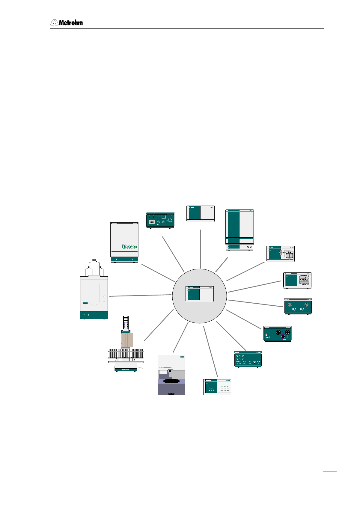
Fig. 1 shows an overview of all the Metrohm instruments which can be
connected to the 830 IC Interface and are described in these ‘Instructions for Use’. It is also possible to connect Bischoff instruments;
please refer to the «IC Net» on-line program help as well as the relevant
Bischoff instruction manuals.
761 Compact IC
766/788 IC Sample Processor
817 Bioscan
791 IC VA Detector
Triathlon Autosampler
819 IC Detector
820 IC Separation Center
818 IC Pump
833 IC Liquid Handling Unit
830 IC Interface
812 IC Valve Unit
816 IC Eluent Selector
828 IC Dual Suppressor
837 IC Inline Degasser
Fig. 1: Connection possibilities at 830 IC Interface
830 IC Interface / 8.830.1003 Instructions for Use
1
Page 8
1 Introduction
1.2 Parts and controls
In this section you will find the numbers and designations of the parts
and controls of the 830 IC Interface. The numbering applies throughout the instructions for use, i.e. bold numbers in the text (e.g.
to the parts and controls illustrated here.
1
5
) refer
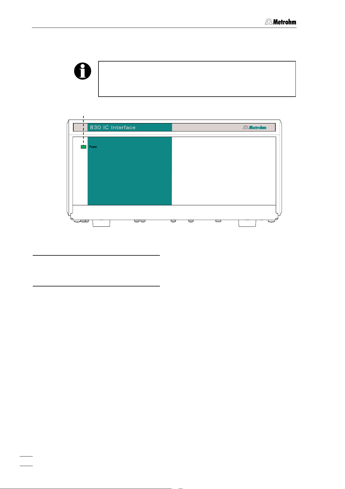
Fig. 2: Front of 830 IC Interface
Mains pilot lamp
1
Lights up when instrument is switched
on
2
830 IC Interface / 8.830.1003 Instructions for Use
Page 9
1.2 Parts and controls
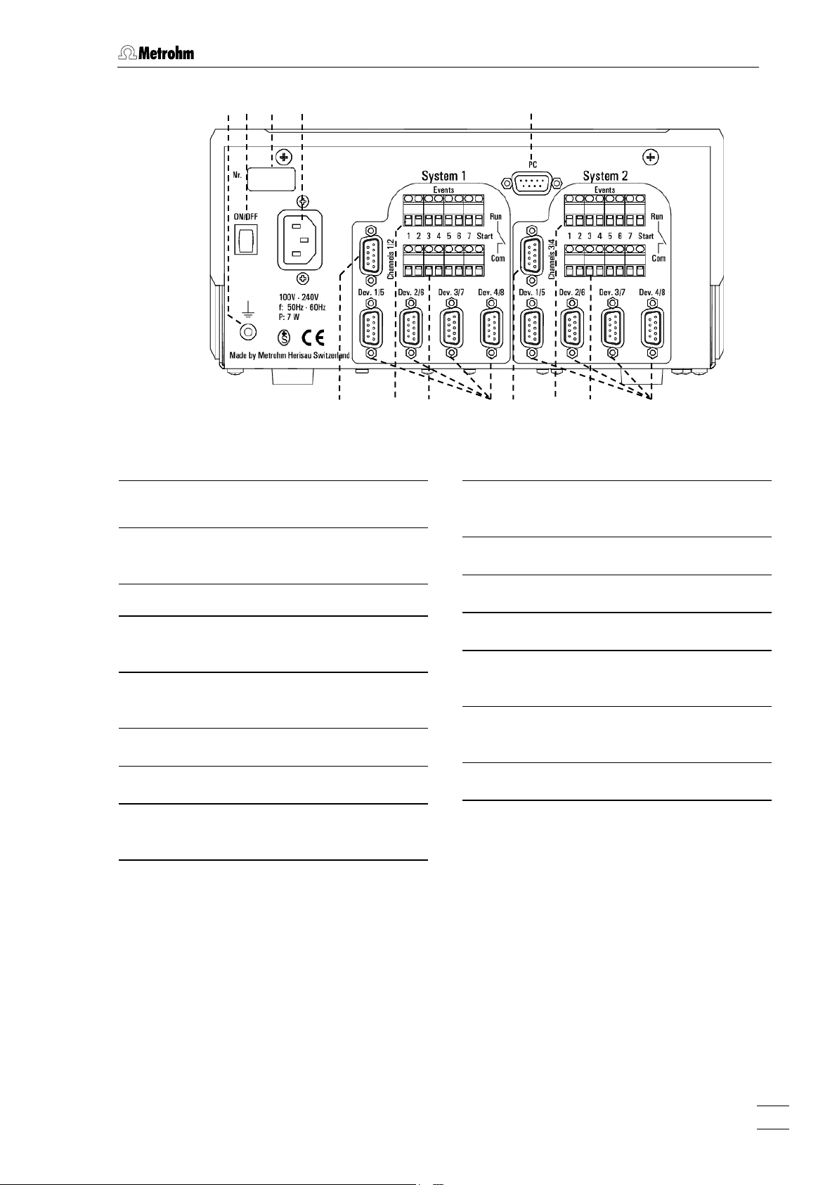
2 3 4 5
Fig. 3: Rear of 830 IC Interface
Earthing socket
2
Mains switch
3
For switching the instrument on/off.
Serial number
4
6
7 8 9 10 11 12 13 14
Remote input/output lines connec-
9
tion (COM)
RS232 interfaces
10
System 2
Mains connection plug
5
Mains connection see section 2.2
PC connection
6
RS232 interface
System 1
Analog signal connection
7
Remote input/output lines connec-
8
tion (RUN)
Analog signal connection
11
Remote input/output lines connec-
12
tion (RUN)
Remote input/output lines connec-
13
tion (COM)
RS232 interfaces
14
830 IC Interface / 8.830.1003 Instructions for Use
3
Page 10

1 Introduction
1.3 Information on the Instructions for Use
Please read through these Instructions for Use carefully before you put
the 830 IC Interface into operation. The Instructions for Use contain
information and warnings to which the user must pay attention in order
to assure safe operation of the instrument.
1.3.1 Organization
These 8.830.1003 Instructions for Use for the 830 IC Interface provide a comprehensive overview of the installation, startup procedure,
operation and technical specifications of this instrument. The Instructions for Use are organized as follows:
Section 1 Introduction
Section 2 Installation
General description of instrument, parts and controls and safety notes
Mains connection, connection to PC,
connection of external instruments
Section 3 Operation
Operation via «IC Net»
Section 4 Appendix
Technical data, standard equipment, options, warranty, declarations of conformity, index
To find the required information on the instruments you will find it an
advantage to use either the Table of contents or the Index at the
back.
4
830 IC Interface / 8.830.1003 Instructions for Use
Page 11
1.3 Information on the Instructions for Use
1.3.2 Notation and pictograms
The following notations and pictograms (symbols) are used in these Instructions for Use:
Range Menu item, parameter or entry
value
in «IC Net» program
SYSTEM STATE Program window
in «IC Net» program
<OK> Button
in «IC Net» program
4 Part or control of 830
Danger/Warning
This symbol indicates a possible
risk of death or injury to the user
and possible damage to the
instrument or its components by
electricity.
Danger/Warning
This symbol indicates a possible
risk of death or injury to the user
and possible damage to the
instrument or its components.
Attention
This symbol indicates important
information that you should read
before continuing.
Information
This symbol indicates additional
information and tips which may be
of particular use to you.
830 IC Interface / 8.830.1003 Instructions for Use
5
Page 12
1 Introduction
1.4 Safety notes
While electrical safety in the handling of the 830 IC Interface is assured
in the context of the specifications IEC 1010-1 (protection class 1, degree of protection IP40), the following points should be noted:
• Mains connection
The mains connection must be effected in accordance with the
instructions in section 2.2.
• Opening the instrument
Inside the instrument there are no parts which must be set or adjusted
by the user.
If the 830 IC Interface is connected to the power supply, the instrument must not be opened nor must parts be removed from it, otherwise there is a danger of coming into contact with components which
are live. Hence, always disconnect the instrument from all voltage
sources before you open it and ensure that the mains cable is
5
disconnected from mains connection
!
• Protection against static charges
Electronic components are sensitive to static charging and can be
destroyed by discharges. Before you touch any of the components
inside the 830 IC Interface, you should earth yourself and any tools
you are using by touching an earthed object (e.g. housing of the
instrument or a radiator) to eliminate any static charges which exist.
6
830 IC Interface / 8.830.1003 Instructions for Use
Page 13

2.1 Setting up the instrument
2 Installation
2.1 Setting up the instrument
2.1.1 Packaging
The 830 IC Interface is supplied together with the separately packed
accessories in special packagings containing shock-absorbing foam
linings designed to provide excellent protection. The instrument itself is
packed in an evacuated polyethylene bag to prevent the ingress of
dust. Please store all these special packagings as only they assure
transport of the instrument free from damage.
2.1.2 Check
After receipt, immediately check whether the shipment is complete and
has arrived without damage (compare with delivery note and list of
accessories in section 4.2). In the case of transport damage, see
instructions in section 4.5.1 "Warranty".
2.1.3 Location
Position the instrument in the laboratory at a location convenient for operation, free from vibrations and protected against a corrosive atmosphere and contamination by chemicals.
2.1.4 Arrangement of the instruments
The modular IC instruments can be piled up in any order. The best
place for the 830 IC Interface is on top of a modular IC system.
The 830 IC Interface should always be placed above components
carrying liquids so that any leaks which may occur in the tubing or
connections cannot cause damage by leakage of liquids (e.g. acid).
830 IC Interface / 8.830.1003 Instructions for Use
7
Page 14
2 Installation
2.2 Mains connection
2.2.1 Mains voltage and fuses
The 830 Interface has a power supply which automatically adjusts itself
to the existing mains voltage (100…240 V) and frequency (50…60 Hz).
It is equipped with an electronic overload protection device and also
has two fuses; however, these should only be exchanged by Metrohm
service technicians.
2.2.2 Mains cable
The instrument is supplied with one of three mains cables
• 6.2122.020 with plug SEV 12 (Switzerland, …)
• 6.2122.040 with plug CEE(7), VII (Germany, …)
• 6.2133.070 with plug NEMA 5-15 (USA, …)
which are three-cored and fitted with a plug with an earthing pin. If a different plug has to be fitted, the yellow/green lead (IEC standard) must
be connected to the earthing socket 2 (protection class 1).
Any break in the earthing inside or outside the instrument can make it
a hazard!
Plug the mains cable into mains connection plug 5 at the 830 IC Interface (see Fig. 3).
2.2.3 Switching the instrument on/off
The 830 IC Interface is switched on and off using mains switch 3 (see
Fig. 3). When the instrument is switched on a start-up check routine is
running the mains pilot lamp 1 flashes twice slowly and remains on.
8
830 IC Interface / 8.830.1003 Instructions for Use
Page 15
2.3 Connection to the PC
2.3 Connection to the PC
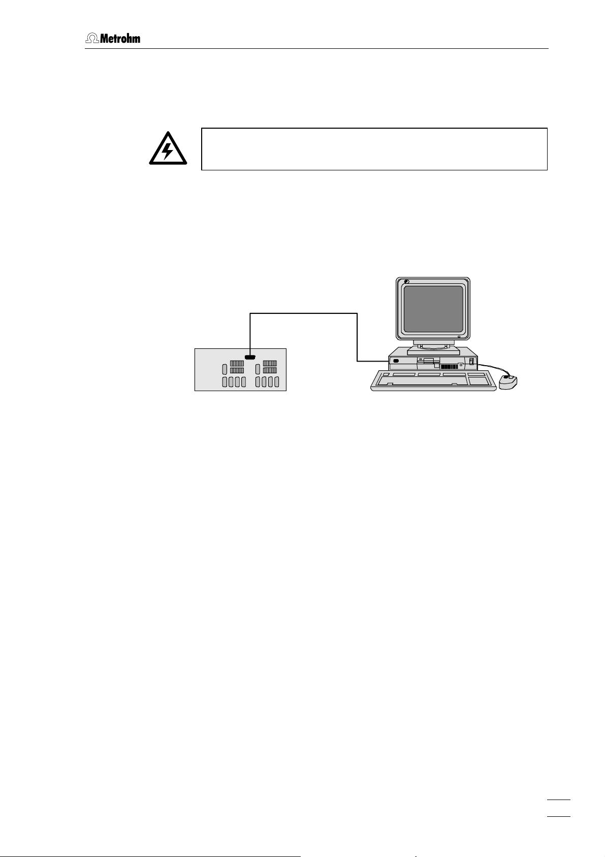
2.3.1 Connecting cable
Always switch off 830 IC Interface and PC before you connect the two
instruments with the 6.2134.100 Cable
Connect the PC connection 6 at the 830 IC Interface to one of the serial
COM ports at the PC using the 6.2134.100 Cable (9 pin/9 pin). If only a
25-pin COM interface is available on the PC then the 6.2125.110
Adapter cable or a commercially available adapter must be used.
6.2134.100
830
Fig. 4: Connection of 830 IC Interface to PC
2.3.2 Software installation
The PC program «IC Net 2.3» is required for the operation of the 830 IC
Interface; this is contained on the 6.6034.033 CD included in the accessories. This program runs under Windows 2000 and Windows XP operating systems and is installed according to section 1.4.2 of the «IC Net»
Instructions for Use.
830 IC Interface / 8.830.1003 Instructions for Use
9
Page 16
2 Installation
2.4 Connection of external instruments
2.4.1 General information
Before an external instrument is connected to the 830 IC Interface, the
3
830 IC Interface must always be switched off using mains switch
Each system of the two versions of the 830 IC Interface has four RS232
interfaces 10 or 14 for connection of a maximum of 8 external instruments, an 7 or 11 interface for analog signals from a maximum of 2 detectors and 8 remote output lines 8/9 or 12/13 for controlling external
instruments by making contacts or impulses (see Fig. 3). Information
about the technical data of these interfaces is given in section 4.1.
For installation and startup of external instruments proceed as follows:
1 Switch off all instruments
!
• Switch off 830 IC Interface and all external instruments using
the mains switch.
2 Connect instruments
• Connect the instruments to the 830 IC Interface according to
the connection diagrams shown in sections 2.4.2 to 2.4.15 by
using the cables named in the diagrams. Other instrument
combinations can be set up by using these examples as a
guide.
3 Switch on all instruments
• Switch on 830 IC Interface and all external instruments using
the mains switch.
4 Instrument settings
Operation with the 830 IC Interface requires that the following
settings must be made:
• Advanced IC instruments:
818 IC Pump
819 IC Detector
820 IC Separation Center
833 IC Liquid Handling Unit
These instruments are already pre-configured, no additional
settings must be made.
Also all other Metrohm IC instruments can be operated with the
830 IC Interface, for the settings of the instruments please refer
to the respective instructions for use.
• 732 IC Detector:
>CONFIG/RS settings
handshake: SWchar
10
830 IC Interface / 8.830.1003 Instructions for Use
Page 17

2.4 Connection of external instruments
>CONFIG/RS settings
RS control: on
• 709 IC Pump:
Switch on external control of the 709 IC Pump using the
[ EXT. ] key.
• 752 IC Pump Unit, 753 IC Suppressor Module,
754 IC Dialysis Unit:
Switch on external control via remote interface using the
[ Remote ] switch.
• 817 Bioscan:
This instrument is already pre-configured, no additional settings must be made.
• 761 Compact IC:
This instrument is already pre-configured, no additional settings must be made.
• 750 IC Autosampler:
Always switch on the 830 IC Interface first and then the 750
Autosampler.
• 766 IC Sample Processor:
>RS232 settings
handshake: SWchar
>RS232 settings
RS control: on
• Triathlon Autosampler:
This instrument is already pre-configured, no additional settings must be made.
• 812 IC Valve Unit:
This instrument is already pre-configured, no additional settings must be made.
• 816 IC Eluent Selector:
Switch on external control via RS232 interface using the
[ EXT ] switch..
• 828 IC Dual Suppresso:
Switch on external control via remote interface using the
[ Remote ] switch.
• 837 IC Degasser:
This instrument is already pre-configured, no additional settings must be made.
5 Create new system in «IC Net»
• Start the «IC Net» program.
• Create a new system file with the selected instruments (de-
830 IC Interface / 8.830.1003 Instructions for Use
tails see IC Net Instructions for Use).
11
Page 18

2 Installation
2.4.2 819 IC Detector, 820 IC Separation Center, 818 IC Pump
Example
Analysis of anions or cations on a modular system with electronic suppression.
Instruments
The setup of the instruments corresponds to the Modular IC System 1
(MIC 1 Advanced).
• 2.830.0020 830 IC Interface
• 2.819.0110 819 IC Detector
• 2.820.0210 820 IC Separation Center with 1 injector and
column heater
• 2.818.0110 818 IC Pump
819
6.2134.130
820
6.2115.070
PC
6.2134.100
818830
6.2134.040
6.2134.090
Interconncection
Fig. 5: Connection of 819, 820 and 818 (MIC 1)
6.2125.090
12
830 IC Interface / 8.830.1003 Instructions for Use
Page 19

2.4 Connection of external instruments
2.4.3 833 IC Liquid Handling Pump Unit
Example
Analysis of anions or cations on a modular system with chemical suppression.
Instruments
The setup of the instruments corresponds to the Modular IC System 2
(MIC 2 Advanced).
• 2.830.0020 830 IC Interface
• 2.819.0110 819 IC Detector
• 2.820.0230 820 IC Separation Center with 1 injector,
suppressor module and column heater
• 2.818.0110 818 IC Pump
• 2.833.0010 833 IC Liquid Handling Pump Unit
819
6.2134.130
820
6.2125.090
6.2115.070
PC
6.2134.100
818830
6.2134.040
6.2134.090
6.2128.180
833
Interconnection
Fig. 6: Connection of 820, 819, 818 and 833(Pump Unit) (MIC 2)
830 IC Interface / 8.830.1003 Instructions for Use
13
Page 20

2 Installation
2.4.4 833 IC Liquid Handling Suppressor-Unit
Example
Simultaneous analysis of cations and anions on a modular system with
two independent detectors.
Instruments
The setup of the instruments corresponds to the Modular IC System 3
(MIC 3 Advanced).
• 2.830.0020 830 IC Interface
• 2.819.0010 819 IC Detector for System 1 (cations)
• 2.819.0110 819IC Detector für System 2 (anions)
• 2.820.0220 820 IC Separation Center with 2 injectors and
column heater
• 2.818.0110 818 IC Pump, for System 1 (cations)
• 2.818.0110 818 IC Pumpe, for System 2 (anions)
• 2.833.0020 833 IC Liquid Handling Suppressor Unit,
for System 2 (anions)
PC
Interconnection
6.2134.100
6.2134.130
6.2134.130
6.2134.040
6.2134.090
819-1
820
6.2115.070
818-1830
6.2125.090
6.2115.070
819-2
6.2125.090
818-2
833
6.2143.200
6.2134.090
6.2128.180
Fig. 7: Connection of 2
×
819, 820, 2×818 and 833 (Suppressor Unit)
(MIC 3)
14
830 IC Interface / 8.830.1003 Instructions for Use
Page 21

2.4 Connection of external instruments
2.4.5 833 IC Liquid Handling Sample Prep Unit
Example
Neutralization of an alkaline sample for anion determination with chemical suppression.
Instruments
The setup of the instruments corresponds to the Modular IC System 6
(MIC 6) enhanced by the IC Liquid Handling Sample Prep Module
833 (2.833.0030).
• 2.830.0020 830 IC Interface
• 2.819.0110 819 IC Detector
• 2.820.0220 820 IC Separation Center with 2 injectors and
column heater
• 2.818.0110 818 IC Pump
• 2.833.0010 833 IC Liquid Handling Pump Unit
• 2.833.0020 833 IC Liquid Handling Suppressor Unit
• 2.833.0030 833 IC Liquid Handling Sample Prep Unit
Interconnection
830
6.2134.130
6.2134.040
6.2128.180
PC
6.2134.100
6.2134.090
833 Sample Prep
833 Suppressor
6.2115.070
833 Pump
6.2128.180
6.2143.210
6.2143.200
819
820
B (LOOP) A (PCC)
6.2128.180
818
6.2125.120
6.2141.110
6.2125.090
766
6.2134.090
Fig. 8: Connection of 833 (Sample Prep Unit) to MIC 6 for Neutralization
830 IC Interface / 8.830.1003 Instructions for Use
15
Page 22

2 Installation
2.4.6 833 IC Liquid Handling Dialysis Unit
Example
Analysis of anions on a modular system with chemical suppression after preceding sample dialysis.
Instruments
• 2.830.0020 830 IC Interface
• 2.819.0110 819 IC Detector
• 2.820.0220 820 IC Separation Center 820 with 2 injectors and
column heater
• 2.818.0110 818 IC Pump
• 2.833.0020 833 IC Liquid Handling Suppressor Unit
• 2.833.0040 833 IC Liquid Handling Dialysis Unit
Interconnection
819
6.2134.130
6.2143.220
820
6.2125.090
6.2115.070
833 Dialysis
PC
6.2134.100
818830
6.2134.040
6.2134.090
833 Suppressor
Fig. 9: Connection of 819, 820, 818, 833 (Suppressor Unit) and
833 (Dialysis Unit)
16
830 IC Interface / 8.830.1003 Instructions for Use
Page 23

2.4 Connection of external instruments
2.4.7 833 IC Liquid Handling Ultra Filtration Unit
Example
Analysis of anions on a modular system with chemical suppression after preceding sample filtration, for strongly contaminated samples.
Instruments
• 2.830.0020 830 IC Interface
• 2.819.0110 819 IC Detector
• 2.820.0210 820 IC Separation Center 820 with 1 injector and
column heater
• 2.818.0110 818 IC Pump
• 2.833.0020 833 IC Liquid Handling Suppressor Unit
• 2.833.0050 833 IC Liquid Handling Ultra Filtration Unit
Interconnection
819
6.2134.130
6.2143.220
820
6.2125.090
6.2115.070
833 Ultra Filtration
PC
6.2134.100
818830
6.2134.040
6.2134.090
833 Suppressor
Fig. 10: Connection of 819, 820, 818, 833 (Suppressor Unit) and
833 (Ultra Filtration Unit)
830 IC Interface / 8.830.1003 Instructions for Use
17
Page 24

2 Installation
2.4.8 Triathlon Autosampler
Example
Automatic analysis of anions or cations on a modular system with electronic suppression using the Triathlon Autosampler.
Instruments
• 2.830.0020 830 IC Interface
• 2.819.0110 819 IC Detector
• 2.820.0210 820 IC Separation Center 820 with 1 injector and
column heater
• 2.818.0110 818 IC Pump
• 2.135.0100 Triathlon Autosampler
Interconnection
819
6.2134.130
820
6.2125.090
6.2115.070
Triathlon
PC
6.2134.100
818830
6.2134.040
6.2134.090
6.2134.000
Fig. 11: Connection of 819, 820, 818 and Triathlon
18
830 IC Interface / 8.830.1003 Instructions for Use
Page 25

2.4 Connection of external instruments
2.4.9 766 IC Sample Processor
Example
Automatic analysis of anions or cations on a modular system with electronic suppression using the 766 IC Sample Processor.
Instruments
• 2.830.0020 830 IC Interface
• 2.819.0110 819 IC Detector
• 2.820.0210 820 IC Separation Center 820 with 1 injector and
column heater
• 2.818.0110 818 IC Pump
• 2.766.0010 766 IC Sample Processor
Interconnection
819
6.2134.130
820
6.2125.090
6.2115.070
PC
6.2134.100
818830
766
6.2134.040
6.2134.090
6.2134.080
6.2141.110
Fig. 12: Connection of 819, 820, 818 and 766
830 IC Interface / 8.830.1003 Instructions for Use
19
Page 26

2 Installation
2.4.10 791 IC VA Detector
Example
Analysis of anions or cations on a modular system with electronic suppression and with simultaneous conductometric and electrochemical
detection.
Instruments
• 2.830.0020 830 IC Interface
• 2.819.0110 819 IC Detector
• 2.820.0210 820 IC Separation Center with 1 injector and
column heater
• 2.818.0110 818 IC Pump
• 2.791.0020 791 IC VA Detector
Interconnection
819
6.2134.130
820
6.2125.090
6.2115.070
6.2134.100
6.2134.040
PC
818830
6.2134.090
6.2128.130
791
Fig. 13: Connection of 819, 820, 818 and 791
20
830 IC Interface / 8.830.1003 Instructions for Use
Page 27

2.4 Connection of external instruments
2.4.11 761 Compact IC
Example
Connection of a modular system and a 761 Compact IC to a 830 IC Interface (if not enough COM ports are available at the PC).
Instruments
• 2.830.0020 830 IC Interface
• 2.819.0110 819 IC Detector
• 2.820.0210 820 IC Separation Center with 1 injector and
column heater
• 2.818.0110 818 IC Pump
• 2.761.0020 761 Compact IC with suppressor module
Interconnection
819
6.2134.130
820
6.2125.090
6.2115.070
761
PC
6.2134.100
818830
6.2134.040
6.2134.090
6.2134.100
Fig. 14: Connection of 819, 820, 818 and 761
830 IC Interface / 8.830.1003 Instructions for Use
21
Page 28

2 Installation
2.4.12 812 IC Valve Unit and 817 Bioscan
Example
Modular system for sugar analysis.
Instruments
The setup of the instruments corresponds to the Modular IC System 8
(MIC 8 Advanced) enhanced by the 830 IC Interface.
• 2.830.0020 830 IC Interface
• 2.817.0010 817 Bioscan
• 2.812.0010 812 IC Valve Unit 812 with 1 valve
• 2.818.0110 818 IC Pump
Interconnection
817
1
AUX 1
AUX 2
1 2 3 4 5 6 7 8 9
2
+ Adapter 6.2125.150
812
PC
6.2134.100
830
6.2134.090
6.2128.100
818
Fig. 15: Connection of 817, 812 and 818 (MIC 8)
Ground
Fill
Inject
22
830 IC Interface / 8.830.1003 Instructions for Use
Page 29

2.4 Connection of external instruments
2.4.13 816 IC Eluent Selector
Example
Analysis of anions on a modular system with chemical suppression and
step gradients.
Instruments
• 2.830.0020 830 IC Interface
• 2.819.0110 819 IC Detector
• 2.820.0230 820 IC Separation Center with 1 injector,
suppressor module and column heater
• 2.818.0110 818 IC Pump
• 2.816.0010 816 IC Eluent Selector
Interconnection
819
6.2134.130
820
6.2115.070
PC
6.2134.100
818830
6.2134.040
6.2134.090
6.2134.080
Fig. 16: Connection to 819, 820, 818 and 816
6.2125.090
816
830 IC Interface / 8.830.1003 Instructions for Use
23
Page 30

2 Installation
2.4.14 828 IC Dual Suppressor
Example
Analysis of anions on a modular system using binary high-pressure
gradients with chemical suppression.
Instruments
The setup of the instruments corresponds to the Modular IC System 10 (MIC 10 Advanced)
• 2.830.0020 830 IC Interface
• 2.819.0110 819 IC Detector
• 2.820.0210 820 IC Separation Center with 1 injector,
suppressor module and column heater
• 2.818.0110 818 IC Pump, 2 devices
• 2.828.0010 828 IC Dual Suppressor
PC
6.2134.100
830
6.2134.130
819
6.2125.090
820
6.2134.040
6.2115.070
828
6.2128.180
818
6.2134.090
818
6.2134.080
Interconnection
Fig. 17: Connection to 819, 820, 2x818 and 828 (MIC 10)
24
830 IC Interface / 8.830.1003 Instructions for Use
Page 31

2.4 Connection of external instruments
2.4.15 837 IC Combi Degasser
Example
Analysis of anions on a modular system with chemical suppression and
automatic degassing of sample and eluent.
Instruments
• 2.830.0020 830 IC Interface
• 2.819.0110 819 IC Detector
• 2.820.0230 820 IC Separation Center with 1 injector and
suppressor module and column heater
• 2.818.0010 818 IC Pump
• 2.837.0030 837 IC Combi Degasser
Interconnection
819
6.2134.130
820
6.2115.070
PC
6.2134.100
818830
6.2134.040
6.2134.090
6.2128.180
Fig. 18: Connection to 819, 820, 818 and 837
6.2125.090
837
830 IC Interface / 8.830.1003 Instructions for Use
25
Page 32
3 Operation
3 Operation
The operation of 830 IC Interface is made completely via the Metrohm
software «IC Net».
This section describes only the most important points concerning the
operation of the 830 IC Interface. For further details please refer to the
«IC Net» Instructions for Use and to the on-line help in the PC program.
3.1 Switch instrument on/off
The 830 IC Interface is switched on and off using mains switch 3 on the
rear of the instrument (see Fig. 3).
After the instrument has been switched on a self-test is running. The
mains pilot lamp 1 flashes twice slowly and remains on to show that the
instrument is ready for use, if an error ocurrs the mains pilot lamp 1
starts flashing fast.
If the mains pilot lamp is flashing fast after the instrument is switched
on an error occured. Switch the instrument off and on, if the error
remains, refer to the Metrohm service.
26
830 IC Interface / 8.830.1003 Instructions for Use
Page 33

3.2 Settings in the "830 IC Interface" window
3.2 Settings in the "830 IC Interface" window
By clicking the 830 icon in the toolbar with the left mouse button or by
Open
Init
clicking this icon with the right mouse button and selecting the
menu item the
It consists of three tabs
830 IC Interface window for parameter settings is opened.
Init, RS settings, and Links.
The Init tab of the 830 IC Interface window contains data acquisition parameters for the 830 IC Interface.
Label Optional label to name the interface with
maximum 8 characters.
ROM version Instrument program version number .
Measuring per second Number of data points measured per s.
Entry range: 10, 20, 30, 50, 60 points/s
Range Range for AD converter .
Example: converts ± 2500 mV to 224 bits
Entry range:
39.062 mV
<SET> Send current parameters to 830 IC Interface.
2500, 1250, 625, 312.5, 156.25, 78.125,
830 IC Interface / 8.830.1003 Instructions for Use
27
Page 34

3 Operation
RS settings
The
RS settings tab of the 830 IC Interface window contains RS232 pa-
rameters for the 830 IC Interface.
Protected Protocol
Data transfer with Protected Protocol between
830 IC Interface and PC for enhanced data secu-
rity.
Data transfer without Protected Protocol be-
tween
if there is a problem with the RS communication
using the Protected Protocol.
Baud Rate Display of the baud rate of the device.
Parity Display of the parity check .
Handshake Display of the software handshake mode.
FIFO size Display of the intermediate memory in byte.
The values are displayed correctly only if the 830 IC Interface is connected and switched on.
830 IC Interface and PC, select this option
28
830 IC Interface / 8.830.1003 Instructions for Use
Page 35

3.2 Settings in the "830 IC Interface" window
Links
The
Links tab of the 830 IC Interface is used for RS232 interface (COM
port) selection and settings.
Alias Name of the instrument.
COM # If this entry is clicked with the right mouse but-
ton, the following menu appears:
Put on desktop Possibility for setting RS232 interface parame-
ters (details see on-line help).
Change Possibility for changing the RS232 interface.
The following window is opened, where the
COM port can be changed by clicking on the
desired entry.
830 IC Interface / 8.830.1003 Instructions for Use
29
Page 36

3 Operation
3.2.1 Event output lines
830 System [1] or 830 System [2] window are available in the SYSTEM
The
window if the
Install existing devices option. The 830 System [#] window with pro-
the
grams and settings for the seven event output lines is opened by selecting the
clicking the
tabs
Time program
On the
program for the event output lines of the 830 IC Interface can be entered. This program is started automatically as defined in the
window either at the moment the determination is started (
termination
Program and Events setup.
Program tab of the 830 System [#] window a user-defined time
830 System [1] or 830 System [2] have been installed with
Open menu item with the right mouse button or by double-
830 icon added to the SYSTEM window. It consists of the
Start mode
Start with de-
) or at the moment the sample is injected (Start with inject).
The Program tab contains the two following subpages::
Program Main time program with all program steps.
Events configuration Possibility for creation of user-defined remote
commands.
30
830 IC Interface / 8.830.1003 Instructions for Use
Page 37

3.2 Settings in the "830 IC Interface" window
Program
On the
Program subpage, program steps including time, program in-
struction and parameter can be entered.
Erste Spalte Time at which program instruction is applied.
Entry range:
0.0 ... 999.9 min
If no time is entered, the program instruction is
applied together with the last instruction with
time entry.
Zweite Spalte Program instruction (see below).
In addition to these predefined instructions,
user-defined remote commands can be entered if activated on the
Dritte Spalte Parameter for program instruction (see below).
ENABLED Enable program start (a disabled program is
Events configuration tab.
not started).
<Add> Add new program instruction.
<Delete> Delete selected program instruction.
<Verify> Test the time program (error messages are dis-
played if program is wrong).
List of program instructions
The following program instructions can be added to the time program
on the
Instruction
Events 0, 1, p, * Set event output lines 1...7 to the desired
Program subpage:
Entry Meaning
values. For entry of the first value, enter
or
*. For entry of the other values, move the
1, 0, p
cursor in front of the value to be changed and
enter
1, 0, p or *.
Program END, RESET The END flag can be used to end a program,
especially if the program time should be longer
than the chromatogram duration. Additional
steps after this flag are not allowed. The
RESET
flag is used to reset the parameters to the
system startup values.
830 IC Interface / 8.830.1003 Instructions for Use
31
Page 38

3 Operation
Events configuration
On the
Events configuration subtab user-defined event commands can
be defined, which can be inserted into a time program after being activated with
<Activate>.
Name (1st column) User-definable name of the event command
(e.g.
Start_766).
Remotebefehl (2nd column)
Setting the event output lines 1…7.
Selection:
0 (line off, inactive, open)
1 (line on, active, 0 V)
p (pulse, pulse length 150 ms)
* (leave line in current status)
For entry of the first value, enter
entry of the other values, move the cursor in
front of the value to be changed and enter
p or *.
<Add> Add new remote command.
<Delete> Delete selected remote command.
<Activate> Activate the defined remote commands for in-
sertion into the time program.
1, 0, p or *. For
1, 0,
32
830 IC Interface / 8.830.1003 Instructions for Use
Page 39

3.2 Settings in the "830 IC Interface" window
Events setup
The
Events setup tab of the 830 System [#] window contains the startup
values for the seven event output lines of system 1 or system 2 of the
830 IC Interface. These startup values are sent each time the system is
connected or a determination is started.
Each event output line can be set to the following values:
0 Line off, inactive (open)
1 Line on, active (0 V)
For technical data to the event output lines see section 4.1.
830 IC Interface / 8.830.1003 Instructions for Use
33
Page 40

4 Appendix
4 Appendix
4.1 Technical data
Mains connection
Voltage 100...240 V
Frequency 50...60 Hz
Power consumption 7 W
Fuse 2 × 1 ATH (to be replaced by Metrohm Service
PC interface (RS232)
Connector Dsub connector 9 pin (male)
Baud rate 1'200…115'200
Provided that nothing to the contrary is mentioned, the
published data are typical values for the 830 IC Interface
at an ambient temperature of 25°C.
only using the same type)
Additional electronic overload protection
15
96
Data bits 8
Stop bits 1
Handshake Xon/Xoff, none
Parity none, even, odd
FIFO 0…16 Bytes
Pin assignment
Pin 1,4,6: internally connected
Pin 2: RxD (Received Data)
Pin 3: TxD (Transmitted Data)
Pin 5: GND (Signal Ground)
Pin 7,8: internally connected
34
830 IC Interface / 8.830.1003 Instructions for Use
Page 41

4.1 Technical data
t
Rs232 interfaces
Connector Dsub connector 9 pin (male)
15
96
Baud rate 1'200…115'200 (für Dev. 8 1'200…19'200)
Data bits 7, 8
Stop bits 1, 2
Handshake Xon/Xoff, none
Parity none, even, odd
FIFO 0…16 Bytes (für Dev. 8 not available)
Pin assignment
Remote interface (Events)
Output lines
Input lines
Pin 2: RxD (Received Data) for Dev. 1…4
Pin 3: TxD (Transmitted Data) for Dev. 1…4
Pin 5: GND (Signal Ground) for Dev. 1…4
Pin 7: TxD (Transmitted Data) for Dev. 5…8
Pin 8: RxD (Received Data) for Dev. 5…8
Pin 9: GND (Signal Ground) for Dev. 5…8
7 potential-free relay contacts per system for
controlling external instruments.
RUN
Maximum contact load:
30 V / 1 A DC
COM
1 digital input per system for external method
start.
+5V
470k
47k
RUN
Ext. Star
COM
Maximum load for external contact:
approx. 0.1 mA at max. cut-off voltage of approx.
5 V
830 IC Interface / 8.830.1003 Instructions for Use
35
Page 42

4 Appendix
Analog signal interface
Function
2 potential-free analog signal inputs per system.
Connector Dsub connector 9 pin (female)
15
69
Input voltage range ± 2.5 V
Input amplification 1, 2, 4, 8, 16, 32, 64 (selectable)
Sampling rate 10, 20, 30, 50, 60 measuring pooints/s
Resolution 24 bit (1 LSP = 0.298 µV at amplification 1)
Noise < 20 µVpp
< 3 µVrms (at 0 V input voltage, amplification 1
and sampling rate 10 Hz)
Zero error ± 2.5 mV
Pin assignment
Pin 1,4,5,8,9: GND (ground, connected to
housing)
Pin 2: Analog 1+
Pin 3: Analog 1–
Pin 6: Analog 2+
Pin 7: Analog 2–
Safety specifications
Construction/testing according to EN/IEC 61010-1 / UL 3101-1,
protection class 1, degree of protection IP40
Safety directions The Instructions for Use include information and
warnings which must be heeded by the user to
assure safe operation of the instrument.
Electromagnetic compatibility (EMC)
Emitted interference Standards met:
- EN/IEC 61326
- EN 55022
- CISPR 22
Immunity to interference Standards met:
- EN/IEC 61326
- EN/IEC 61000-4-2
- EN/IEC 61000-4-3
- EN/IEC 61000-4-4
- EN/IEC 61000-4-5
- EN/IEC 61000-4-6
- EN/IEC 61000-4-8
- EN/IEC 61000-4-11
- EN/IEC 61000-4-14
- NAMUR
36
830 IC Interface / 8.830.1003 Instructions for Use
Page 43

4.1 Technical data
Ambient temperature
Nominal operating range +5…+45°C
(at 20…80 % atmospheric humidity)
Storage, transport –20…+70°C
Housing
Material of cover Polyurethane rigid foam (PUR) with fire protection
for fire class UL94VO, CFC-free
Material of base Steel, enameled
Dimensions
Width 260 mm
Height 130 mm
Depth 340 mm
Weight (with accessories) 4.8 kg
830 IC Interface / 8.830.1003 Instructions for Use
37
Page 44

4 Appendix
4.2 Scope of delivery
Subject to changes !
The 830 IC Interface 2.830.0020 for 2 IC systems includes the following
parts:
Quant. Order-No. Description
2 6.2115.070 Remote Connection cable
Connection cable 830 IC Interface –
820 IC Separation Center
2 6.2134.130 Connection cable
Connection cable 830 IC Interface –
819 IC Detrector
2 6.2134.090 RS232 connection cable
Connection cable 830 IC Interface –
2 external devices (818, 819, 766,
etc.)
1 6.2134.100 RS232 connection cable
Connection cable 830 IC Interface –
PC
1 6.6034.033 Software CD «IC Net 2.3»
1 6.2122.0X0 Mains cable
according to customer's specification:
Cable socket
Type IEC 320/C 13 Type SEV 12 (CH…) ............................... 6.2122.020
Type IEC 320/C 13 Type CEE (7), VII (D…)........................... 6.2122.040
Type CEE (22), V Type NEMA 5-15 (USA…) ...................... 6.2122.070
1 8.830.1003 Instructions for Use (english)
for 830 IC Interface
1 8.110.8283 Instructions for Use «IC Net» (english)
for PC program «IC Net 2.3»
1 8.110.8293 Compliance White Paper (english)
for PC program «IC Net 2.3»
1 8.110.8303 Administrator Manual «IC Cap 1.0» (english)
for PC program «IC Cap 1.0»
Cable plug
1 8.110.8309 User Manual «IC Cap 1.0» (english)
for PC program «IC Cap 1.0»
38
830 IC Interface / 8.830.1003 Instructions for Use
Page 45

4.3 Optional accessories
1 8.110.8213 Instructions for Use «Autodatabase» (english)
for PC program «Autodatabase 1.0»
1 8.110.8207 Registration card
4.3 Optional accessories
Order-No. Description
6.2128.130 Connection cable
Connection cable 830 IC Interface – 732
analog output (channel 1/2 or 3/4)
6.2128.180 Remote connection cable
Connection cable 830 IC Interface – 833
6.2134.000 RS232 connection cable
Connection cable 830 IC Interface –
Triathlon Autosampler
6.2134.080 RS232 connection cable
Connection cable 830 IC Interface –
1 external device (818, 819, 766, etc.)
6.2141.110 Connection cable
Connection cable 830 IC Interface –
819 IC Detector– 766/788 IC Sample
Processor (accessory part of 766/788)
830 IC Interface / 8.830.1003 Instructions for Use
39
Page 46

4 Appendix
4.4 Validation / GLP
GLP (Good Laboratory Practice) requires, among other things, that the
precision and correctness of analytical instruments is checked at regular intervals by using SOPs (Standard Operating Procedures, SOP). An
example of such a standard operating procedure is available from
Metrohm under the title «Application Bulletin No. 277 – Validation of
Metrohm Ion Chromatography Systems by using Standard Operating Procedures (SOP)». This SOP can be adapted for your ion
chromatography system and used for its validation.
The 830 IC Interface must be included as a part of the whole ion chromatography system, whose most important components include the
pumps, separation columns, detector and evaluation system, in the allembracing validation of the whole system.
Please contact your local Metrohm agency in order to receive support in
validating your 830 IC Interface. It can also provide you with validation
documentation which will help you to carry out your installation qualification (IQ) and operational qualification (OQ).
Further information about QA, GLP and validation can also be found in
the brochure «Quality management with Metrohm» which is also obtainable from your local Metrohm agency.
Checking the electronic and mechanical assemblies of Metrohm instruments can and should be undertaken within the framework of regular servicing by Metrohm technicians. All Metrohm instruments are
equipped with start-up check routines which check that the relevant assemblies are functioning perfectly when the instrument is switched on. If
no error message appears it can be assumed that the instrument is
functioning properly.
The 830 IC Interface also contains a built-in diagnosis program which
allows the service technicians to check the functioning of particular assemblies should faults or malfunctions occur and to localize them.
40
830 IC Interface / 8.830.1003 Instructions for Use
Page 47

4.5 Warranty and Conformity
4.5 Warranty and Conformity
4.5.1 Warranty
The warranty on our products is limited to defects that are traceable to
material, construction or manufacturing error which occur within 12
months from the day of delivery. In this case, the defects will be rectified in our workshops free of charge. Transport costs are to be paid by
the customer.
For day and night operation, the warranty is limited to 6 months.
Glass breakage in the case of electrodes or other parts is not covered
by the warranty. Checks which are not a result of material or manufacturing faults are also charged during the warranty period. For parts of
outside manufacture insofar as these constitute an appreciable part of
our instrument, the warranty stipulations of the manufacturer in question
apply.
With the regard to the guarantee of accuracy, the technical specifications in the instruction manual are authoritative.
Concerning defects in material, construction or design as well as the
absence of guaranteed features, the orderer has no rights or claims except those mentioned above.
If damage of the packaging is evident on receipt of a consignment or if
the goods show signs of transport damage after unpacking, the carrier
must be informed immediately and a written damage report demanded.
lack of an official damage report releases Metrohm from any liability to
pay compensation.
If any instruments and parts have to be returned, the original packaging
should be used if at all possible. This applies above all to instruments,
electrodes, burette cylinders and PTFE pistons. Before embedment in
wood shavings or similar material, the parts must be packed in a dustproof package (for instruments, use of a plastic bag is imperative). If
open assemblies are enclosed in the scope of delivery that are sensitive to electromagnetic voltages (e.g. data interfaces etc.) these must
be returned in the associated original protective packaging (e.g. conductive protective bag). (Exception: assemblies with built-in voltage
source belong in a non-conductive protective packaging).
No warranty responsibility whatsoever will be accepted by Metrohm for
damage which arises as a result of non-compliance with these instructions.
830 IC Interface / 8.830.1003 Instructions for Use
41
Page 48

4 Appendix
4.5.2 Declaration of Conformity
This is to certify the conformity to the standard specifications for electrical appliances and accessories, as well
as to the standard specifications for security and to
system validation issued by the manufacturing company.
Name of commodity 830 IC Interface
System software Stored in ROMs
Name of manufacturer Metrohm Ltd., Herisau, Switzerland
Description
PC controlled chromatography data system for remote control of IC instruments and
for automatic evaluation of chromatograms.
This Metrohm instrument has been built and has undergone final type testing according to the
standards:
CH-9101 Herisau, Switzerland
Tel. +41 71 353 85 85
Fax +41 71 353 89 01
www.metrohm.com
Electromagnetic compatibility: Emission
EN/IEC 61326, EN 55022 / CISPR 22
Electromagnetic compatibility: Immunity
EN/IEC 61326, EN/IEC 61000-4-2, EN/IEC 61000-4-3, EN/IEC 61000-4-4, EN/IEC 61000-4-5, EN/IEC
61000-4-6, EN/IEC 61000-4-8, EN/IEC 61000-4-11, EN/IEC 61000-4-14, NAMUR
Safety specifications
EN/IEC 61010-1, UL 3101-1 protection class I
It has also been certified by ElectroSuisse, which is member of the International Certification Body
(CB/IEC).
The instrument meets the requirements of the CE mark as contained in the EU directives 89/336/EEC
and 73/23/EEC and fulfils the following specifications:
EN 61326 Electrical equipment for measurement, control and laboratory use – EMC requirements
EN 61010-1 Safety requirements for electrical equipment for measurement, control and laboratory
use
Metrohm Ltd. is holder of the SQS-certificate of the quality system ISO 9001 for quality assurance in
design/development, production, installation and servicing.
The system software, stored in Read Only Memories (ROMs) has been validated in connection
with standard operating procedures in respect to functionality and performance.
The technical specifications are documented in the instruction manual.
Herisau, May 28, 2003
Dr. J. Frank Ch. Buchmann
Development Manager Production and
Quality Assurance Manager
42
830 IC Interface / 8.830.1003 Instructions for Use
Page 49

4.5 Warranty and Conformity
4.5.3 Quality Management Principles
Metrohm Ltd., CH-9101 Herisau, Switzerland
CH-9101 Herisau/Switzerland
E-Mail info@metrohm.com
Internet www.metrohm.com
Metrohm Ltd. holds the ISO 9001 Certificate, registration number 10872-02, issued by
SQS (Swiss Association for Quality and Management Systems). Internal and external audits are carried out periodically to assure that the standards defined by Metrohm’s QM
Manual are maintained.
The steps involved in the design, manufacture and servicing of instruments are fully
documented and the resulting reports are archived for ten years. The development of
software for PCs and instruments is also duly documented and the documents and
source codes are archived. Both remain the possession of Metrohm. A non-disclosure
agreement may be asked to be provided by those requiring access to them.
The implementation of the ISO 9001
quality system is described in Metrohm’s
QM Manual, which comprises detailed
instructions on the following fields of
activity:
Instrument development
The organisation of the instrument
design, its planning and the intermediate
controls are fully documented and
traceable. Laboratory testing accompanies all phases of instrument development.
Software development
Software development occurs in terms of
the software life cycle. Tests are
performed to detect programming errors
and to assess the program’s functionality in a laboratory environment.
Components
All components used in the Metrohm
instruments have to satisfy the quality
standards that are defined and implemented for our products. Suppliers of
components are audited by Metrohm as
the need arises.
Manufacture
The measures put into practice in the
production of our instruments guarantee
a constant quality standard. Production
planning and manufacturing procedures,
maintenance of production means and
testing of components, intermediate and
finished products are prescribed.
Customer support and service
Customer support involves all phases of
instrument acquisition and use by the
customer, i.e. consulting to define the
adequate equipment for the analytical
problem at hand, delivery of the equipment, user manuals, training, after-sales
service and processing of customer
complaints. The Metrohm service organisation is equipped to support customers in implementing standards such
as GLP, GMP, ISO 900X, in performing
Operational Qualification and Performance Verification of the system components or in carrying out the System
Validation for the quantitative determination of a substance in a given matrix.
830 IC Interface / 8.830.1003 Instructions for Use
43
Page 50

4 Appendix
4.6 Index
7
709 IC Pump
Settings ....................................10
732 IC Detector
Settings ....................................10
750 IC Autosampler
Settings ....................................10
752 IC Pump Unit
Settings ....................................10
753 IC Suppressor Module
Settings ....................................10
754 IC Dialysis Unit
Settings ....................................10
761 Compact IC
Connection to 830 ................... 21
Settings ....................................10
766 IC Sample Processor
Connection to 830 ................... 19
Settings ....................................10
791 IC VA Detector
Connection to 830 ................... 20
8
812 IC Valve Unit
Connection to 830 ................... 22
Settings ....................................10
816 IC Eluent Selector
Connection to 830 ................... 23
Settings ....................................10
817 Bioscan
Connection to 830 ................... 22
Settings ....................................10
818 IC Pump
Connection to 830 ................... 12
Settings ....................................10
819 IC Detector
Connection to 830 ................... 12
Settings ....................................10
820 IC Separation Center
Connection to 830 ................... 12
Settings ....................................10
828 IC Dual Suppressor
Connection to 830 ................... 24
Settings ....................................10
833 IC Liquid Handling Unit
Dialysis Unit
Connection to 830 ............. 16
Pump Unit
Connection to 830 ............. 13
Sample Prep Unit
Connection to 830 ............. 15
Settings ....................................10
Suppressor Unit
Connection to 830 ............. 14
Ultra Filtration Unit
Connection to 830 ............. 17
837 IC Degasser
Connection to 830 ................... 25
Settings ....................................10
A
<Activate> ................................... 32
AD converter ................................27
<Add>.................................... 31, 32
Advanced IC instruments
Settings ....................................10
Alias ..............................................29
Ambient temperature ...................37
Analog connection
11
Figure...................................3
Technical Data...................36
7
Figure...................................3
Technical Data...................36
Analog signal interface.................36
Appendix ......................................34
Arrangement of the instruments ....7
Attention .........................................5
B
Baud Rate .....................................28
C
Cable
6.2125.070................................38
6.2125.110..................................9
6.2128.130................................39
6.2128.180................................39
6.2134.000..........................38, 39
6.2134.080................................39
6.2134.100............................9, 38
6.2134.130................................38
6.2141.110................................39
CE mark........................................ 42
Change .........................................29
Check .............................................7
COM # ..........................................29
Compliance White Paper
IC Net 2.3 8.110.8193 ..............38
Connection possibilities ................. 1
Connections
Figure .........................................3
Technical Data .....................34 ff
to external instruments.............10
to PC........................................... 9
Contents .......................................... I
D
Danger............................................ 5
Declaration of Conformity ............42
Degree of protection ................6, 36
<Delete> ................................ 31, 32
Dimensions ..................................37
E
Earthing ......................................6, 8
Earthing socket 2
Figure .........................................3
Electrical safety ..............................6
Electromagnetic compatibility...... 36
EMC.............................................. 36
Emitted interference ..................... 36
ENABLED ......................................31
END............................................... 31
Event output lines......................... 30
Events ........................................... 31
Events configuration .....................32
Events setup..................................33
External instruments .....................10
External start .................................35
F
FIFO size .......................................28
Front................................................2
Fuse ..............................................34
G
GLP ........................................ 40, 43
GMP..............................................43
H
Handshake ....................................28
Housing ........................................37
I
Illustrations
List ..............................................II
Immunity to interference...............36
Information......................................5
Information on the Instructions for
Use..................................................4
Init .................................................27
Installation.......................................7
Instructions for Use
830 IC Interface 8.830.1003 .4, 38
Autodatabase 8.110.8213........39
IC Cap 1.0 8.110.8303 .............38
IC Cap 1.0 8.110.8309 .............38
IC Net 2.3 8.110.8193 ..............38
Instrument
Description .................................1
Switch on/off.............................26
Introduction.....................................1
IQ ..................................................40
ISO 9100.......................................42
L
Label .............................................27
leakage ...........................................7
Links..............................................29
List
of illustrations..............................II
List of program instructions..........31
Location ..........................................7
M
Mains cable
Mains connection .......................8
Ordering designation ...............38
Mains connection
Procedure ...................................8
Safety notes................................6
Mains connection plug 5
Figure..........................................3
Mains connection .......................8
Mains frequency ...........................34
828 IC Dual Suppressor/ Gebrauchsanweisung 8.828.1001
44
Page 51

4.6 Index
Mains pilot lamp 1
Error ..........................................26
Figure..........................................2
Ready for use display...........8, 26
Mains switch 3
Figure..........................................3
Switching the instrument
on/off.....................................8, 26
Mains voltage ...........................8, 34
Measuring per second ..................27
MIC 1 ............................................12
MIC 2 ............................................13
MIC 3 ............................................14
MIC 6 ............................................15
MIC 8 ............................................22
MIC 10 ..........................................24
N
Name the interface .......................27
Notation ..........................................5
Number of data points .................27
O
Opening the instrument..................6
Operation
via IC Net ..................................26
Optional accessories....................39
OQ ................................................40
Organization ...................................4
P
Packaging.......................................7
Parity.............................................28
Parity check ..................................28
Parts and controls ..........................2
PC connection 6
Connection to the PC .................9
Figure..........................................3
PC interface 6
Technical Data..........................34
Pictograms .....................................5
Power consumption .....................34
Program ..................................30, 31
Program instruction ......................31
Program step ............................... 31
Programm version number.......... 27
Protected Protocol........................ 28
Protection class ................... 6, 8, 36
Protective earth.............................. 8
Pulse ............................................ 32
Put on desktop ............................. 29
Q
QA ................................................ 40
Quality assurance ........................ 40
Quality Management ................... 43
R
Range ........................................... 27
Rear................................................ 3
Registration card 8.110.8207 ...... 39
Remote connection
12
Figure .................................. 3
13
Figure .................................. 3
8
Figure .................................. 3
Technical Data .................. 35
9
Figure .................................. 3
Remote connection 12
Technical Data......................... 35
Remote connection 13
Technical Data......................... 35
Remote connection 9
Technical Data......................... 35
Remote input lines ....................... 35
Remote output lines............... 30, 35
RESET .......................................... 31
ROM version................................. 27
RS settings................................... 28
RS232 interface 10
Figure......................................... 3
Technical Data......................... 35
RS232 interface 14
Figure......................................... 3
Technical Data......................... 35
RS232 parameters....................... 28
S
Safety directions........................... 36
Safety notes ................................... 6
Safety specifications .................... 36
Scope of delivery ......................... 38
Serial number 4
Figure ......................................... 3
<SET>.......................................... 27
Setting up the instrument............... 7
Settings ........................................27
Software CD 6.6034.033.............. 38
Software installation ....................... 9
SOP .............................................. 40
Standard operating procedures ..40
Static charges ................................6
Storage......................................... 37
Switch instrument on/off ..............26
Switching on/off the instrument .....8
T
Technical data.............................. 34
Time program............................... 30
Transport........................................ 7
Transport damage .......................41
Triathlon Autosampler
Connection to Triathlon............ 18
Settings ....................................10
U
User-defined event commands ... 32
V
Validation...................................... 40
<Verify> ....................................... 31
W
Warning .......................................... 5
Warranty ....................................... 41
830 IC Interface / 8.830.1003 Instructions for Use
45
 Loading...