

Page 1
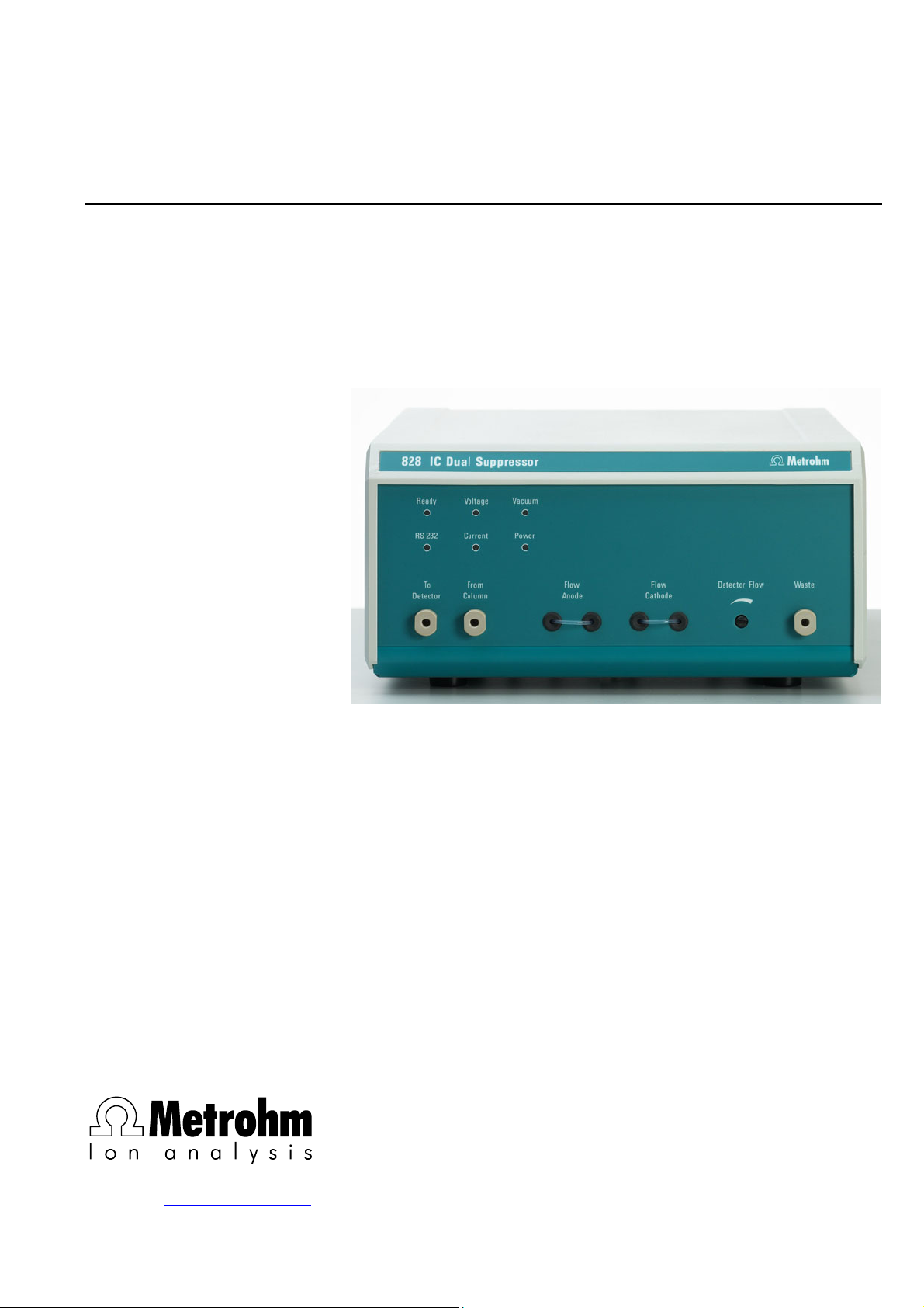
828 IC Dual Suppressor
CH-9101 Herisau/Switzerland
E-Mail info@metrohm.com
Internet www.metrohm.com
Instructions for Use
8.828.1003
Page 2

Page 3

CH-9101 Herisau/Switzerland
E-Mail info@metrohm.com
Internet www.metrohm.com
828 IC Dual Suppressor
Instructions for Use
8.828.1003 09.2002 / pkl
Page 4

Teachware
Metrohm AG
Oberdorfstrasse 68
CH-9101 Herisau
teachware@metrohm.com
1st Edition 2002
These instructions are protected by copyright. All rights reserved.
Although all the information given in these instructions has been checked with great care, errors
cannot be entirely excluded. Should you notice any mistakes please inform the author at the
address given above.
Page 5

Contents
Table of contents
1 Introduction.................................................... 1
1.1 Instrument description ............................................................. 1
1.2 How it works.............................................................................. 2
1.3 Parts and controls .................................................................... 4
1.4 Information about the Instructions for Use ............................. 7
1.4.1 Organization ..................................................................................7
1.4.2 Notation and pictograms ..............................................................8
1.5 Safety notes ..............................................................................9
1.5.1 Electrical safety..............................................................................9
1.5.2 General safety measures ..............................................................9
2 Installation ................................................... 10
2.1 Instrument setup..................................................................... 10
2.1.1 Packaging.................................................................................... 10
2.1.2 Checks.........................................................................................10
2.1.3 Location ....................................................................................... 10
2.2 Connecting the accessories................................................... 11
2.2.1 Attaching the CO2 absorber cartridge ........................................11
2.3 Mains connection.................................................................... 12
2.3.1 Mains voltage ..............................................................................12
2.3.2 Fuse.............................................................................................12
2.3.3 Mains cable and mains connection ............................................13
2.3.4 Switching the instrument on/off...................................................13
2.4 Connecting to a modular gradient IC system ....................... 14
2.4.1 Electrical connections .................................................................14
2.4.2 Connecting the IC Dual Suppressor ...........................................15
2.4.3 Settings in IC Net 2.1...................................................................17
2.5 Connecting to the 761 Compact IC........................................ 19
2.5.1 Electrical connection ...................................................................19
2.5.2 Connecting the IC Dual Suppressor ...........................................19
2.5.3 Settings for control by the 761 PC Software 1.1 ......................... 20
3 Operation...................................................... 22
3.1 General information................................................................ 22
3.2 Eluent....................................................................................... 23
3.3 Capacity................................................................................... 23
3.4 Degassing unit and CO2 absorber cartridge ......................... 23
3.5 Flow rate ratio ......................................................................... 24
3.5.1 Setting the flow rates ................................................................... 24
3.6 Routine operation ................................................................... 26
3.6.1 Manual operation ........................................................................26
3.6.2 Software control...........................................................................27
4 Troubleshooting - Problems......................... 30
4.1 Remedying faults and problems ............................................ 30
4.2 Chromatography problems .................................................... 30
4.3 Instrument problems ..............................................................32
828 IC Dual Suppressor/ 8.828.1003 Instructions for Use
I
Page 6

Contents
5 Care and maintenance ................................33
5.1 Instrument care ....................................................................... 33
5.2 Maintenance by Metrohm Service ......................................... 33
5.3 Shutdown ................................................................................ 33
5.4 Regular maintenance.............................................................. 33
5.4.1 Replacing the CO2 absorber cartridge .......................................34
5.5 Unplanned maintenance work................................................ 34
5.5.1 Regenerating the cation exchanger............................................ 34
5.5.2 Replacing the suppressor cell .................................................... 35
6 Appendix ....................................................... 39
6.1 Technical data......................................................................... 39
6.1.1 Suppressor cell ...........................................................................39
6.1.2 RS 232 interface.......................................................................... 39
6.1.3 Remote interface ......................................................................... 39
6.1.4 Fault switch, ready output........................................................... 40
6.1.5 Mains connection........................................................................ 40
6.1.6 Safety specifications ...................................................................40
6.1.7 Electromagnetic compatibility (EMC) ......................................... 41
6.1.8 Ambient temperature ..................................................................41
6.1.9 Housing ....................................................................................... 41
6.2 Standard equipment ............................................................... 42
6.3 Optional accessories .............................................................. 44
6.4 Validation / GLP ...................................................................... 45
6.5 Warranty and conformity ........................................................ 46
6.5.1 Warranty ......................................................................................46
6.5.2 EU Declaration of Conformity .....................................................47
6.5.3 Certificate of conformity and system validation.......................... 48
6.6 Index ........................................................................................ 49
828 IC Dual Suppressor/ 8.828.1003 Instructions for Use
II
Page 7

Contents
List of illustrations
Figure 1: Dual suppressor flow diagram............................................. 2
Figure 2: Front panel of the 828 IC Dual Suppressor ......................... 4
Figure 3: Rear panel of the 828 IC Dual Suppressor .......................... 6
Figure 4: Attaching the CO2 absorber cartridge................................ 11
Figure 5: Electrical connections in the MIC 10 system ..................... 14
Figure 6: Flow diagram of the MIC 10............................................... 15
Figure 7: Connecting the 828 IC Dual Suppressor to
the 761 Compact IC ........................................................... 19
Figure 8: Opening the instrument ..................................................... 36
Figure 9: Opened IC Dual Suppressor.............................................. 37
Figure 10: Suppressor cell position, front view ................................... 38
828 IC Dual Suppressor/ 8.828.1003 Instructions for Use
III
Page 8

Contents
List of numbered
parts and controls
LEDs
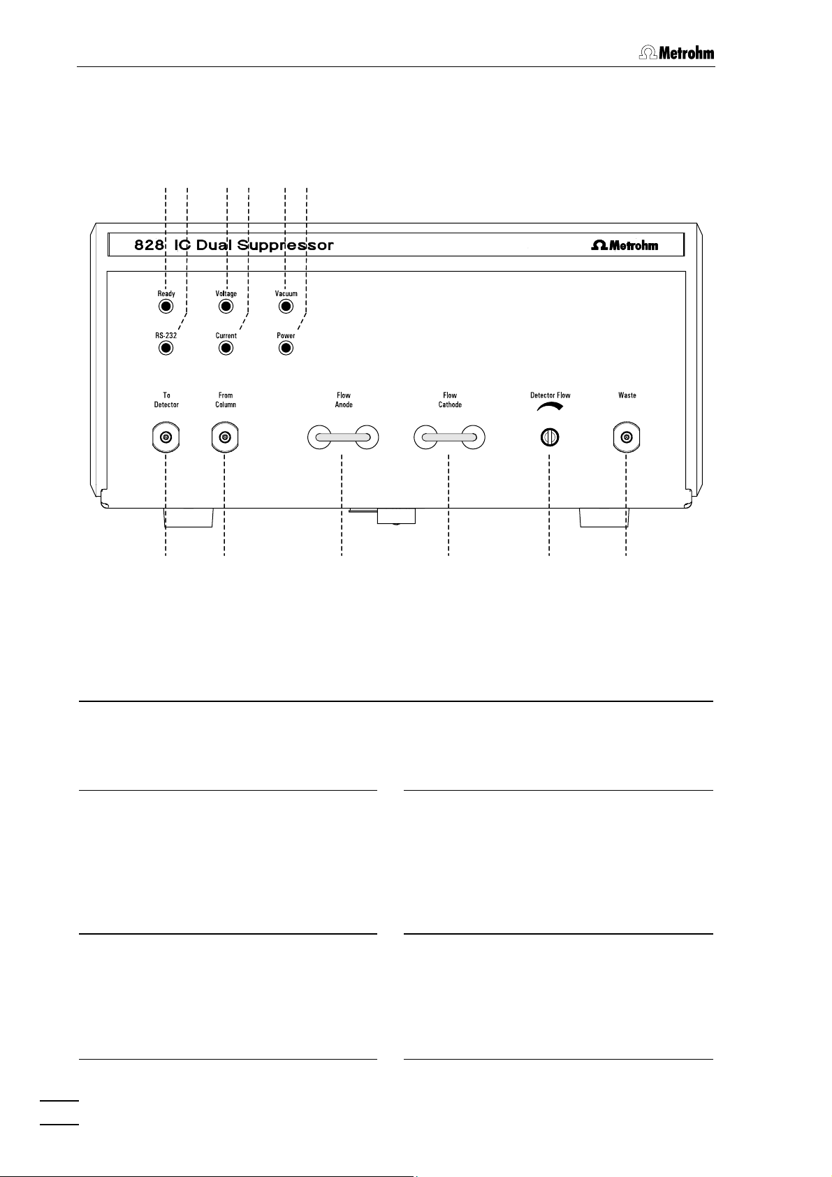
1 Ready ..................................................................................................... 4
2 RS 232.................................................................................................... 4
3 Voltage ................................................................................................... 4
4 Current................................................................................................... 4
5 Vacuum .................................................................................................. 4
6 Power ..................................................................................................... 4
7 Connection To Detector ........................................................................ 5
8 Connection From Column..................................................................... 5
9 Flow anode............................................................................................ 5
10 Flow cathode......................................................................................... 5
11 Detector flow setting screw .................................................................. 5
12 Connection for Waste............................................................................. 5
13 RS-232 interface..................................................................................... 6
14 Holder for CO
15 Remote switch ...................................................................................... 6
16 Fuse holder, mains switch, mains connection ................................ 6
17 Vacuum pump inlet .............................................................................. 6
18 Ready Output interface ......................................................................... 6
19 Type and serial number....................................................................... 6
20 Drain....................................................................................................... 6
21 Remote interface.................................................................................... 6
22 Vacuum pump exhaust ........................................................................ 6
23 Front housing screws........................................................................ 36
24 Rear housing screws......................................................................... 36
25 Housing cover .................................................................................... 36
26 Suppressor cell ..............................................................................36,37
Trap Cartridge ............................................................. 6
2
828 IC Dual Suppressor/ 8.828.1003 Instructions for Use
IV
Page 9
1.1 Instrument description
1 Introduction
1.1 Instrument description
The 828 IC Dual Suppressor is a continuous, regeneration-free solid
phase suppressor which is used to increase the sensitivity of the
detection of anions in ion chromatography.
As well as the usual chemical suppression of the
carbonate/bicarbonate background, in a second suppression step the
suppressor also removes dissolved CO
background conductivity of the mobile phase even further. This results
in an improved signal-to-noise ratio; peak areas in the ppm-range and
above are increased by approx. 30%. At the same time the areas of the
injection peak (water dip) and the system peak are reduced to a
minimum. The reduction of the injection peak means that the detection
of early-eluting anions is improved; the reduction of the system peak
allows the detection of anions which coelute with the system peak. The
baseline drift is also minimized when carbonate/bicarbonate gradients
are used.
in order to reduce the
2
In Metrohm IC systems the 828 IC Dual Suppressor can be remotely
controlled via a remote interface. It can also be combined with all other
commercially available HPLC systems.
828 IC Dual Suppressor/ 8.828.1003 Instructions for Use
1
Page 10
1 Introduction
X
X
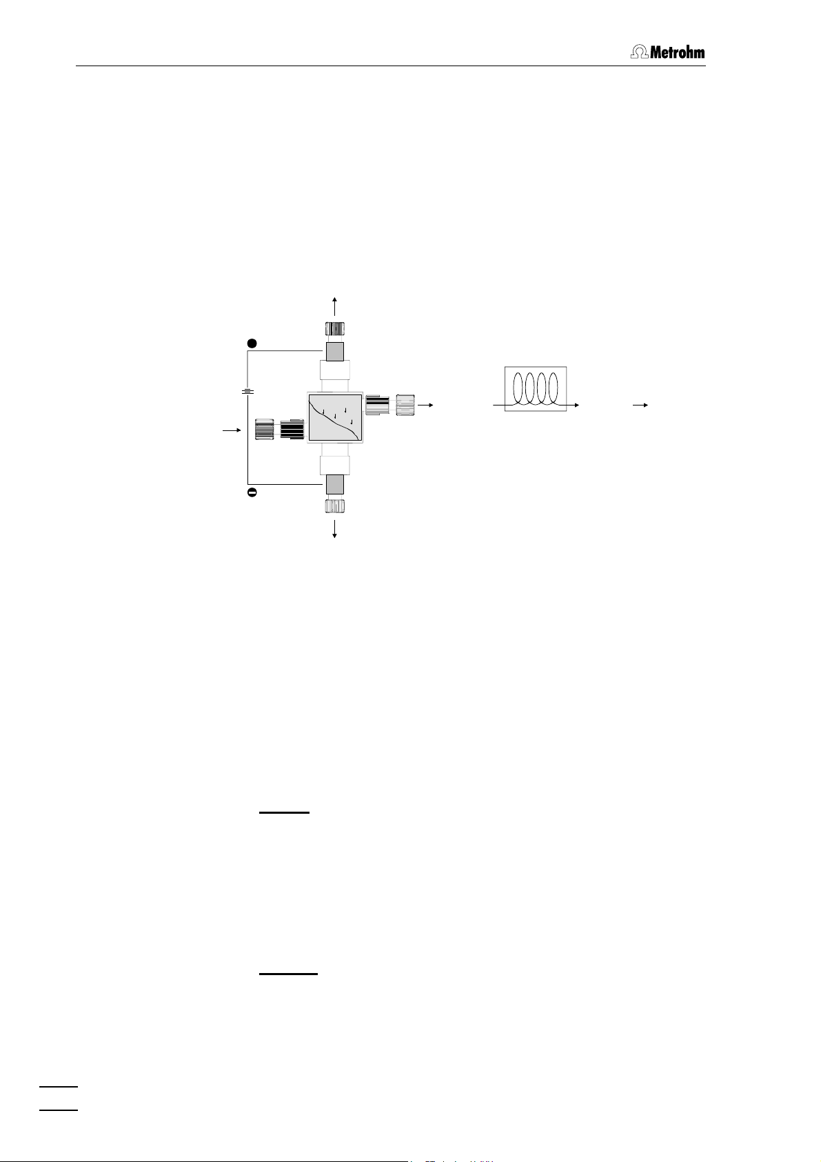
1.2 How it works
The 828 IC Dual Suppressor is used to increase the sensitivity of the
detection of anions in conductivity measurements. It is installed
between the separation column and the conductivity detector. The IC
Dual Suppressor consists of a suppressor cell, a direct current source
and a degassing unit. After it enters the suppressor cell the eluent
containing the sample ions is split proportionally toward the detector,
anode and cathode as shown in Figure 1.
NaHCO
/Na2CO3 + MX
3
+ O2+ H
2 H
2CO3
Anode
+
+
H+
Na+ form
Resin
IN
Cathode
NaOH + MOH + H2+ NaX
2 H2O 4 H++ O2+ 4 e
H+
H+
H+
OUT
2 H2O + 2 e
-
H2CO3+ HX
+2 OH
H
2
-
Degassing Unit
CO2 + H2O
H
2CO3
-
M = Cations (Na+, K+, Mg2+, etc.)
= Anions
H
O + HX
2
To Detector
Figure 1: Dual suppressor flow diagram
Three processes take place simultaneously in the 828 IC Dual
Suppressor:
1. As the eluent and the sample ions emerge from the separation
column an acid/base reaction converts them to their protonated
forms. The cell is packed with a strong cation exchanger which is
present in protonated form. The following exchange reactions occur
in the suppressor:
Eluent:
NaOH + Resin-SO
-H+
Resin-SO
3
-Na+
3
+ H2O
or
NaHCO
/Na2CO3 + Resin-SO
3
-H+
Resin-SO
3
-Na+
3
+ H2CO3
Sample:
MX + Resin-SO
-H+
Resin-SO
3
-M+
3
+ HX
-
-
, NO
X = Cl
, Br-, etc.
3
828 IC Dual Suppressor/ 8.828.1003 Instructions for Use
2
Page 11

1.2 How it works
The counter ions (Na+) of the eluent are exchanged for the hydrogen
+
ions (H
water will be formed; if NaHCO
) of the resin in the cell. If NaOH is used as the eluent then
/Na2CO3 is used as the eluent then
3
carbon dioxide is produced. At the same time the counter ions of the
sample (M
+
= metal cation) are exchanged for protons from the resin.
Together with the sample anions these form acids which have an
increased conductivity, e.g. hydrochloric acid, nitric acid, etc. This
provides an improved signal-to-noise ratio and an improved detection
sensitivity.
2. During the operation of the 828 IC Dual Suppressor a direct current
is constantly applied to the suppressor cell electrodes.
Water in the cell is electrolyzed and the following electrode
reactions take place:
Anode: 2 H
O 4 H+ + O2(g) + 4 e-
2
Cathode: 2 H
O + 2 e- 2 OH- + H2(g)
2
At the anode hydrogen ions and gaseous oxygen are produced; at
the cathode hydroxide ions and gaseous hydrogen. In this way the
hydrogen ions produced at the anode continuously regenerate the
cation exchanger. The sodium cations of the eluent and the cations
of the sample wander toward the cathode in the direct current field.
The eluate that leaves the suppressor cell on the cathode side
contains the hydroxide salts of these cations, gaseous hydrogen
and some sample anions (in the form of their sodium salts). The
eluate at the anode side contains carbonic acid or water together
with gaseous oxygen and some sample ions (protonated form). The
protonated sample anions are eluted toward the detector with
carbonic acid or water.
3. After leaving the suppressor cell all eluates pass through a
degassing unit. Oxygen and hydrogen are removed from the eluate
flows at the anode and cathode sides respectively before they
reach the waste container. The eluate at the OUT connection (see
Figure 1, Figure 10) contains the sample anions and carbonic acid
(if a carbonate/bicarbonate eluent is used) and passes the
degassing unit before reaching the conductivity detector. In the
degassing unit the carbonic acid dissociates to form carbon dioxide
and water. Carbon dioxide is removed and water remains.
This further reduces the background conductivity of the eluate to
provide improved sensitivity and a more stable baseline. This
means that it is possible to use carbonate/bicarbonate gradients.
The injection peak (water dip), which is often overlapped by quickly
eluting anions, and the system peak, which interferes with the
detection of anions which coelute with it, are eliminated.
828 IC Dual Suppressor/ 8.828.1003 Instructions for Use
3
Page 12
1 Introduction
1.3 Parts and controls
12 34 56
78 9 10 11 12
LEDs
The color of the LED indicates the instrument status.
Ready
1
Green: the suppressor is ready for an
analysis.
Red: an error has occurred.
RS-232
2
Green: data transfer via RS 232
connection 13, only for service
purposes.
Figure 2: Front panel of the 828 IC Dual Suppressor
4
5
Current
Green: current is flowing across the
suppressor cell.
Vacuum
Green: the vacuum has operating
pressure.
Red: insufficient vacuum. A leak is
present or the set value has not been
reached within 30 minutes of the
instrument being switched on.
Voltage
3
Green: the voltage applied to the
suppressor cell is within the limits for
normal operation.
Red: the voltage is outside the
operating limits.
828 IC Dual Suppressor/ 8.828.1003 Instructions for Use
4
6
Power
Green: the Dual Suppressor is
switched on, mains voltage is applied.
Page 13

1.3 Parts and controls
To Detector
7
Inlet connection to detector,
connection for 6.1831.010 PEEK
Capillary with 6.2744.010 PEEK
Pressure screw
From Column
8
Outlet connection from column,
connection for 6.1831.010 PEEK
Capillary with 6.2744.010 PEEK
Pressure screw
9 Flow Anode
For a visual check of the anode
eluate. The liquid from the anode
passes through the FEP tubing before
entering the degassing unit. In normal
operation oxygen bubbles should be
seen regularly.
10
Flow Cathode
For a visual check of the cathode
eluate. The liquid from the cathode
passes through the FEP tubing before
entering the degassing unit. In normal
operation hydrogen bubbles should be
seen regularly.
11
Detector Flow
The flow to the detector can be
regulated with a screwdriver.
12 Waste
Outlet to waste container, connection
for 6.1803.020 PTFE Tubing with
6.2744.010 PEEK Pressure screw
828 IC Dual Suppressor/ 8.828.1003 Instructions for Use
5
Page 14
1 Introduction
13 14 15 16
17
18 19 20 21 22
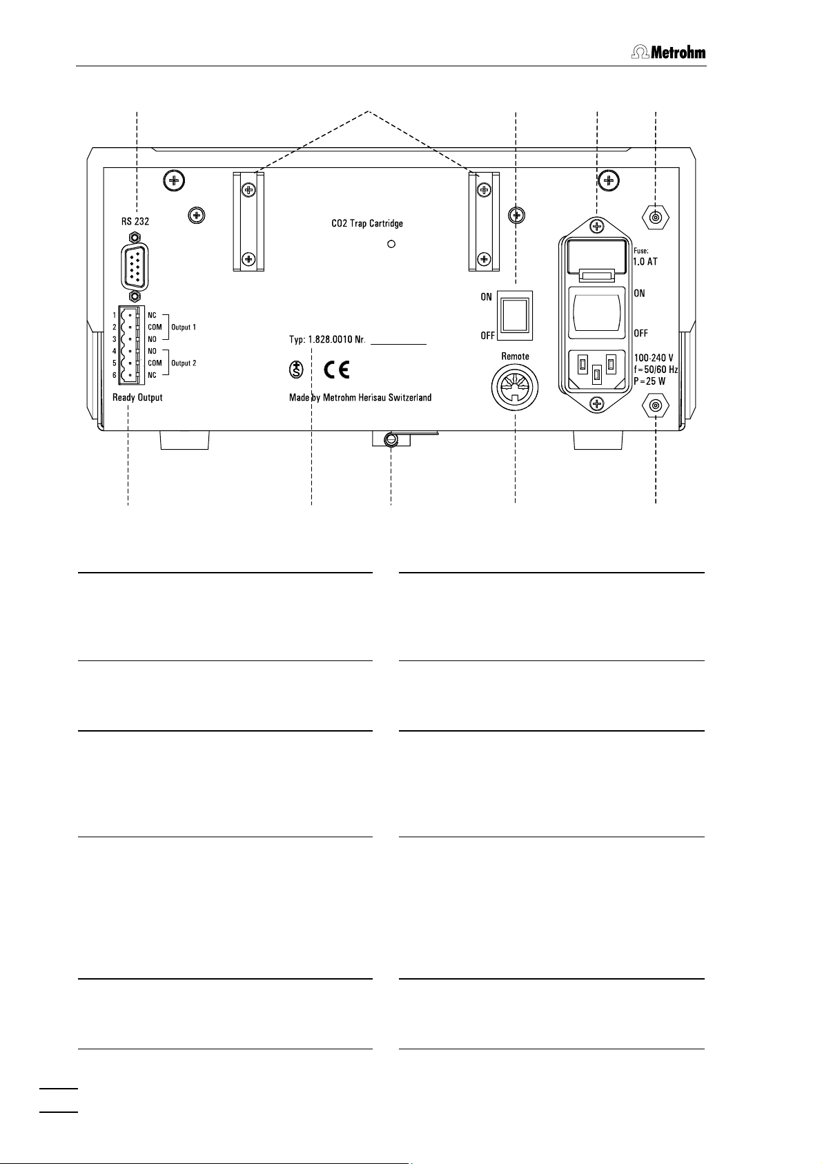
Figure 3: Rear panel of the 828 IC Dual Suppressor
RS 232
13
Interface for service purposes
18
Ready Output
6-pin connector, used as fault switch,
carries status signals (ready/not ready)
to external instruments.
CO
14
Trap Cartridge
2
Holder for CO
absorber-cartridge for
2
19 Type and serial number
cleaning the incoming air
Remote switch
15
Activates the remote control of the
20
Drain
Drain port outlet for liquids
Dual Suppressor via the Remote
connector:
I = ON 0 = OFF
Fuse holder
16
For slow blow fuse 1.0 AT, U.600.0016
Mains switch
21
Remote
Remote interface for remote control by
external instruments.
For switching instrument on/off:
I = ON 0 = OFF
Mains connector
For mains connection see Section 2.3
Vacuum pump inlet
17
Connected to 6.2837.000,
22
Vacuum pump exhaust
see Section 2.2.1
828 IC Dual Suppressor/ 8.828.1003 Instructions for Use
6
Page 15

1.4 Information about the Instructions for Use
1.4 Information about the Instructions for Use
Please study these Instructions for Use carefully before you start to
use the 828 IC Dual Suppressor. The instructions contain information
and warnings that must be observed by the user in order to guarantee
the safe use of the instrument. Please keep these instructions near the
instrument so that they are always to hand when required.
1.4.1 Organization
These 8.828.1003 Instructions for Use for the 828 IC Dual
Suppressor provide you with a comprehensive overview of the
installation, startup, troubleshooting and technical specifications of the
instrument. The installation instructions are arranged as follows:
Sect. 1 Introduction
General description of the instrument, operating parts
and controls, and safety notes
Sect. 2 Installation
Installation of the instrument, mains connection,
connection of the accessories, connection to IC system
Sect. 3 Operation
Information about the operation of the 828 IC Dual
Suppressor
Sect. 4 Troubleshooting - Problems
Possible faults and their remedies
Sect. 5 Care and maintenance
Care and maintenance of the instrument
Sect. 6 Appendix
Technical data, standard equipment, optional
accessories, warranty and declaration of conformity,
index
In order to find the information you require about the 828 Dual
Suppressor you should either use the Contents or the Index.
828 IC Dual Suppressor/ 8.828.1003 Instructions for Use
7
Page 16
1 Introduction
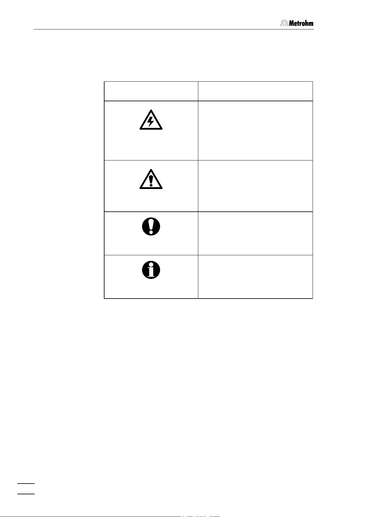
1.4.2 Notation and pictograms
The following notation and pictograms (symbols) are used in these
Instructions:
15 828 parts and controls
Danger/Warning
This symbol indicates a possible
risk of death or injury to the user
and possible damage to the
instrument or its components by
electricity.
Danger/Warning
This symbol indicates a possible
risk of death or injury to the user
and possible damage to the
instrument or its components.
Attention
This symbol indicates important
information that you should read
before continuing.
Information
This symbol indicates additional
information and tips which may be
of particular use to you.
828 IC Dual Suppressor/ 8.828.1003 Instructions for Use
8
Page 17
1.5 Safety notes
1.5 Safety notes
Warning!
This instrument should only be used in accordance with the
information given in these Instructions for Use.
1.5.1 Electrical safety
Electrical safety when handling the 828 IC Dual Suppressor is
guaranteed within the scope of Standard IEC 61010. However, please
observe the following points:
• Mains connection
The mains connection and checking the mains fuse must be
carried out according to the information given in Section 2.3.
• Opening the 828 IC Dual Suppressor
If the 828 IC Dual Suppressor is connected to the mains supply then it
must neither be opened nor should any parts be removed from it, as
otherwise the risk of contact with current-carrying assemblies exists.
This is why the instrument should be separated from all voltage
sources before being opened. Please make sure that the mains
cable is pulled out from mains connector 16!
• Protection against electrostatic charges
Electronic components are sensitive to electrostatic charges and can
be destroyed by a discharge. Before touching any assembly within
the 828 IC Dual Suppressor you should ground yourself and any tool
you are using by grasping a grounded object (e.g. the instrument
housing or a radiator) in order to eliminate any electrostatic charge
which may be present.
1.5.2 General safety measures
• Liquid handling
Check all inlet and outlet tubing for leaks at regular intervals. Observe
the appropriate regulations concerning the handling of flammable
and/or toxic solutions and their disposal.
828 IC Dual Suppressor/ 8.828.1003 Instructions for Use
9
Page 18

2 Installation
2 Installation
2.1 Instrument setup
2.1.1 Packaging
The 828 IC Dual Suppressor and its specially packed accessories are
supplied in very protective special packaging which contains a shockabsorbing plastic foam lining. The instrument itself is contained in an
dustproof evacuated polyethylene bag. Please store this packaging in a
safe place; it is the only way in which the safe transport of the
instrument can be guaranteed.
2.1.2 Checks
Please check that the delivery is complete and undamaged
immediately on receipt (compare with delivery note and list of
accessories given in Section 6.2). If transport damage is evident please
refer to the information given in Section 6.4 “Warranty”.
2.1.3 Location
Place the instrument on a suitable vibration-free laboratory bench,
protected as much as possible from corrosive atmospheres and
contact with chemicals.
Choose a location where the temperature is usually between +5 °C and
+45 °C. The instrument should be protected against excessive
variations in temperature and direct sunlight.
828 IC Dual Suppressor/ 8.828.1003 Instructions for Use
10
Page 19

2.2 Connecting the accessories
2.2 Connecting the accessories
2.2.1 Attaching the CO2 absorber cartridge
A 6.2837.000 CO
accessories of the IC Dual Suppressor. It is attached as follows:
Mount Cartridge Holders 6.2027.070
1
• Remove the lower screws of the holders 14 with a Philips
screwdriver.
• Insert the Cartridge holders 6.2027.070 into the holders 14
from below.
• Reattach the screws.
Attach CO2 Absorber Cartridge
2
• Push the CO2 Absorber Cartridge into the clamps of the
cartridge holders.
Absorber Cartridge is included in the standard
2
• Remove the yellow stopper which seals the cartridge inlet and
connect the CO
absorber cartridge to vacuum inlet 17 using
2
the 6.1816.030 Silicone tubing.
Figure 4: Attaching the CO
Use the yellow stopper to close off the CO
whenever the 828 IC Dual Suppressor is not to be used for a longer
period. This increases the working life of the cartridge.
828 IC Dual Suppressor/ 8.828.1003 Instructions for Use
absorber cartridge
2
absorber cartridge inlet
2
11
Page 20

2 Installation
2.3 Mains connection
Please observe the following rules when connecting the instrument to
the electricity supply. If the instrument is operated with an incorrectly
set mains voltage and/or an incorrect mains fuse then it represents a
fire hazard!
2.3.1 Mains voltage
All power supplies from 100 V to 240 V with 50/60 Hz can be connected
to the mains input of the 828 IC Dual Suppressor. Adaptation to the
mains supply used is carried out automatically.
2.3.2 Fuse
A 1.0 A fuse (slow blow) is contained in the fuse holder of the 828 IC
Dual Suppressor.
Make sure that the instrument is never operated with a different type of
fuse as otherwise it represents a fire hazard!
Changing the fuse
Pull out mains cable
1
Switch off the instrument and remove the mains cable from mains
supply connection 16 of the 828 IC Dual Suppressor.
Remove the fuse holder
2
Use a screwdriver to loosen the fuse holder beside the mains
supply connection (see Figure 3) and remove it completely.
Changing the fuse
3
Change the fuse if necessary and replace it in the fuse holder.
Use only a fuse with the following specifications.
1.0 A fuse (slow blow) Metrohm No. U.600.0016
Re-insert fuse holder
4
828 IC Dual Suppressor/ 8.828.1003 Instructions for Use
12
Page 21

2.3 Mains connection
2.3.3 Mains cable and mains connection
Mains cable
The instrument is supplied with one of the following mains cables
• 6.2122.020 with SEV 12 plug (Switzerland, …)
• 6.2122.040 with CEE(7), VII plug (Germany, …)
• 6.2133.070 with NEMA 5-15 plug (USA, …)
which has three wires and is fitted with a plug with a grounding pin. If a
different plug has to be used then the yellow/green wire (IEC standard)
must be connected to the grounding pin (Protection class I).
Any interruption to the grounding inside or outside the instrument can
represent a hazard!
Mains connection
Insert the mains cable into mains connector 16 of the 828 IC Dual
Suppressor.
2.3.4 Switching the instrument on/off
The 828 IC Dual Suppressor is switched on and off with mains switch
16. When the instrument is switched on the "Power" 6 LED lights up.
828 IC Dual Suppressor/ 8.828.1003 Instructions for Use
13
Page 22

2 Installation
2.4 Connecting to a modular gradient IC system
The 828 IC Dual Suppressor allows the sensible use of the gradient
technique with carbonate/bicarbonate eluents for the first time. The
installation of the 828 IC Dual Suppressor in the system that is most
frequently used, a binary gradient system, is described below.
The required instrument configuration corresponds to the Modular IC
System 10 (MIC 10), an anion system using binary high-pressure
gradients with chemical suppression. It consists of the 762 IC Interface,
732 IC Detector, 733 IC Separation Center (1-channel), 828 IC Dual
Suppressor, two 709 IC Pumps and a gradient mixing spiral with Tpiece and downline pulsation dampener.
The electrical and wet-chemistry connections of this system and its
control using the «IC Net 2.1» software are described below.
2.4.1 Electrical connections
PC
6.2134.100
762
6.2128.130
732
6.2125.090
733
A (LOOP)
6.2115.070
828
6.2128.180
709
6.2134.090
709
6.2134.080
Figure 5: Electrical connections in the MIC 10 system
The electrical connections in the system consisting of the 762 IC
Interface, 732 IC Detector, 733 IC Separation Center (1-channel), 828 IC
Dual Suppressor and two 709 IC Pumps are shown in Figure 5:
828 IC Dual Suppressor/ 8.828.1003 Instructions for Use
14
Page 23

2.4 Connecting to a modular gradient IC system
2.4.2 Connecting the IC Dual Suppressor
The following diagram shows how the system is arranged:
Sample
Gradient
mixing capillary
A Trap column
Valve
IC Pumps
Sample
loop
Separation
column
Inline filter
T-connector
Pulsation
dampener
IC Detector
IC Dual Suppressor
Figure 6: Flow diagram of the MIC 10
All the components should be connected as shown in Figure 6, which
also provides a flow diagram for the sample.
The installation of the other components is described in detail in the
appropriate Instructions for Use.
The 828 IC Dual Suppressor is inserted between the separation column
and the detector. The following connections must be made:
Please ensure that the liquid connections between the separation
column outlet, the Dual Suppressor and the detector inlet are as short
as possible and use a narrow diameter capillary, e.g. 6.1831.010
PEEK Capillary (included as standard). In this way you minimize the
dead volumes and reduce the peak broadening of the signal.
828 IC Dual Suppressor/ 8.828.1003 Instructions for Use
15
Page 24

2 Installation
From Column
1
• Connect the outlet of the separation column in the 733 IC
Separation Center with the inlet of the 828 IC Dual
Suppressor "From Column" 8. Use a 6.1831.010 PEEK
Capillary (i.d. = 0.25 mm, o.d. = 1/16") and a 6.2744.010
Pressure screw for this (both included in standard
equipment).
To Detector
2
• Use another piece of 6.1831.010 PEEK Capillary (i.d. =
0.25 mm, o.d. = 1/16"), further 6.2744.010 Pressure
screws and a 6.2744.040 Coupling (all included in
standard equipment) to connect the outlet of the 828 IC Dual
Suppressor "To Detector" 7 with the inlet of the conductivity
detector in the 732 IC Detector.
Detector outlet
3
• Mount the 6.1803.090 PTFE Capillary (i.d. = 1/16", o.d. =
0.25 mm, 15 m) as a backpressure capillary between the
detector outlet and the waste container. Use a 6.2744.010
Pressure screw and a 6.2744.040 Coupling (all included in
standard equipment) for this.
The backpressure capillary is required to ensure the correct ratio
between the flow rates at the outlets of the suppressor cell, see
Section 3.5.
Check this ratio the first time that a system in which the 828 IC Dual
Suppressor has been newly installed is started up; a detailed
description is given in Section 3.5.1.
To Waste
4
• Connect outlet "Waste" 12 of the 828 IC Dual Suppressor to a
waste container. Use the 6.1803.020 PTFE Tubing (i.d. =
0.97 mm, o.d. = 1.57 mm) and a 6.2744.010 Pressure
screw (both included in standard equipment) for this.
PEEK capillaries that are to be provided with new connections must
have a perfect and plane cutting surface. This is best obtained by
using the optionally available 6.2621.080 Capillary cutter .
828 IC Dual Suppressor/ 8.828.1003 Instructions for Use
16
Page 25

2.4 Connecting to a modular gradient IC system
2.4.3 Settings in IC Net 2.1
On the rear panel of the 828 IC Dual Suppressor switch remote switch
15 to "ON" and also switch mains switch 16 to "ON". The Dual
Suppressor can now be controlled by an external instrument.
Start the IC Net 2.1 software and open the "New System Wizard"
under “File/ New/System....”. This wizard will guide you through the
installation of a new system. Use it to create a system file, e.g.
"Gradient.smt" for your modular gradient system. During the installation
you will be asked about the components of your system. Enter the 762
IC Interface, 732 IC Detector, 733 IC Separation Center (1-channel) and
the two 709 IC Pumps as a Solvent Delivery Unit (SDU) with two pumps
to the system. A detailed description of this procedure is given in the
8.110.8221 Instructions for Use for the Metrodata «IC Net 2.1»
software.
The 828 IC Dual Suppressor has not yet been integrated into the
Version 2.1 of this software and cannot be selected from the list of
devices. This means that you should configure the system without it; its
control commands must then be entered manually.
When you have created the system file "Gradient.smt" the IC Net
window will appear as follows:
The instrument symbols of your detector, the Separation Center and the
two pumps will already appear in your "Gradient.smt" system. As the
Dual Suppressor is controlled via the 762 IC Interface, see Figure 5, you
only have to integrate and configure the interface in the existing system:
• Select the 762 IC Interface under Setup/New devices/Link to
existing device. The instrument symbol will be added to your
system.
828 IC Dual Suppressor/ 8.828.1003 Instructions for Use
17
Page 26

2 Installation
• Double-click on the instrument symbol of the 762 IC Interface to
open its configuration menu and select the file card Events setup.
• The value of the event line, via which the Dual Suppressor will be
controlled, must be set to 1. In this example this is Event Line 1, see
Figure 5.
• Set Event Line 1 to the value 1 and confirm with OK.
The 828 IC Dual Suppressor is now included in the system and will be
controlled by the Metrodata IC Net 2.1 software. It is started together
with the other hardware of the system "Gradient.smt" with SYSTEM
/Control/Startup hardware and shut down with SYSTEM
/Control/Shutdown hardware.
In Metrodata IC Net software versions with version numbers higher
than 2.1 the 828 IC Dual Suppressor will be preconfigured in the
software just like all other Metrohm IC instruments. It can then be
immediately installed in the New System Wizard. A detailed
description can be found in the corresponding Instructions for Use of
the software.
828 IC Dual Suppressor/ 8.828.1003 Instructions for Use
18
Page 27

2.5 Connecting to the 761 Compact IC
2.5 Connecting to the 761 Compact IC
The installation of the 828 IC Dual Suppressor with the 761 Compact IC
and control via the «761 PC Software 1.1» software is described
below.
2.5.1 Electrical connection
The electrical connections of the system consisting of the 761 Compact
IC and the 828 IC Dual Suppressor are made according to Figure 7:
761
6.2134.100
PC
828
Figure 7: Connecting the 828 IC Dual Suppressor
to the 761 Compact IC
2.5.2 Connecting the IC Dual Suppressor
Please ensure that the liquid connections between the separation
column outlet, the Dual Suppressor and the detector inlet are as short
as possible and use a narrow diameter capillary, e.g. 6.1831.010
PEEK Capillary (included as standard). In this way you minimize the
dead volumes and reduce the peak broadening of the signal.
From Column
1
• Connect the outlet of the separation column in the 761
Compact IC to the inlet of the 828 IC Dual Suppressor "From
Column" 8. Use a 6.1831.010 PEEK Capillary (i.d. = 0.25
mm, o.d. = 1/16") and a 6.2744.010 Pressure screw (both
included as standard) for this.
6.2143.200
828 IC Dual Suppressor/ 8.828.1003 Instructions for Use
19
Page 28

2 Installation
To Detector
2
• Use another piece of 6.1831.010 PEEK Capillary (i.d. =
0.25 mm, o.d. = 1/16"), further 6.2744.010 Pressure
screws and a 6.2744.040 Coupling (all included in
standard equipment) to connect the outlet of the 828 IC Dual
Suppressor "To Detector" 7 with the inlet of the conductivity
detector in the 761 Compact IC.
Detector outlet
3
• Mount the 6.1803.090 PTFE Capillary (i.d. = 1/16", o.d. =
0.25 mm, 15 m) as a backpressure capillary between the
detector outlet and the waste container. Use a 6.2744.010
Pressure screw and a 6.2744.040 Coupling (all included in
standard equipment) for this.
The backpressure capillary is required to ensure the correct ratio
between the flow rates at the outlets of the suppressor cell, see
Section 3.5.
Check this ratio the first time that a system in which the 828 IC Dual
Suppressor has been newly installed is started up; a detailed
description is given in Section 3.5.1.
To Waste
4
• Connect outlet "Waste" 12 of the 828 IC Dual Suppressor to a
waste container. Use the 6.1803.020 PTFE Tubing (i.d. =
0.97 mm, o.d. = 1.57 mm) and a 6.2744.010 Pressure
screw (both included in standard equipment) for this.
PEEK capillaries that are to be provided with new connections must
have a perfect and plane cutting surface. This is best obtained by
using the optionally available 6.2621.080 Capillary cutter .
2.5.3 Settings for control by the 761 PC Software 1.1
On the 828 IC Dual Suppressor switch remote switch 15 to "ON" and
also switch mains switch 16 to "ON". The Dual Suppressor can now
be controlled by an external instrument.
In the 761 PC Software 1.1 you must make the following settings:
• Start the 761 PC Software 1.1 and select your system.
828 IC Dual Suppressor/ 8.828.1003 Instructions for Use
20
Page 29

2.5 Connecting to the 761 Compact IC
• Open the instrument control with a double-click on the instrument
symbol of the Compact IC.
If your system is not yet connected to your workplace then the left-hand
window will open, otherwise the right-hand window will open. In each
case the procedure is the same:
• Set the value for Remote Line 1 to 1.
• Save the setting with "Save".
The 828 IC Dual Suppressor is now included in the system and will be
controlled by the 761 PC Software 1.1. The 828 IC Dual Suppressor will
be started as soon as your system is connected to the workplace and
will be shut down together with the 761 Compact IC hardware with
System/Control/Shutdown hardware.
828 IC Dual Suppressor/ 8.828.1003 Instructions for Use
21
Page 30

3 Operation
3 Operation
3.1 General information
No eluent should be pumped through the IC Dual Suppressor when it
is switched off, or if an error occurs. Errors are indicated by red LEDs
on the front panel. Faults which may occur during operation affect the
voltage and the vacuum, which may be outside their specified values.
Details can be found in Section 4 Troubleshooting - Problems.
• During the starting sequence of the instrument (Section 3.6.1) wait
until the vacuum LED lights up green before switching on the eluent
pump.
• A pressure sensor in the instrument is used as the on/off switch for
the electrolysis current of the cell. The current will only be switched
on when a defined pressure has been achieved in the system after
the instrument has been switched on, i.e. if no leaks are present. The
"Current" 4 LED lights up green. If the pressure falls below the
preset value for some time then the current will be switched off.
This ensures that current will only be applied to the cell when liquid
is flowing through the suppressor. This means that the 828 IC Dual
Suppressor can remain switched on even when no eluent is flowing
through it without being damaged. However, in such a case we do
recommend that the IC Dual Suppressor is switched off.
• The 828 IC Dual Suppressor is designed for operation with a total
flow rate of between 0.5 and 2.0 mL/min. Operating the suppressor
with flow rates outside this range may either damage it or produce
unsatisfactory results. At flow rates below 0.5 mL/min the built-up
pressure may not be sufficient to switch on the current. This can
cause the suppressor cell to become exhausted. Flow rates above
2.0 mL/min can create an overpressure in the system and alter the
ratio between the eluates at the anode, cathode and detector outlet
of the cell.
828 IC Dual Suppressor/ 8.828.1003 Instructions for Use
22
Page 31

3.2 Eluent
3.2 Eluent
The cation exchanger resin of the 828 IC Dual Suppressor allows the
use of all the eluents normally used for suppressed ion
chromatography such as hydroxide, borate and carbonate/bicarbonate
eluents, although carbonate/bicarbonate eluents offer the greatest
benefits when used with the 828 IC Dual Suppressor because of the
removal of CO
.
2
In order to achieve the best results you should only use ultrapure
reagents and ultrapure water to prepare your eluents .
3.3 Capacity
The exchange capacity of the suppressor cell of the 828 IC Dual
Suppressor is 50 mmol/L NaOH or 25 mmol/L Na
1 mL/min.
at a flow rate of
2CO3
Check whether the concentration of your eluent and the selected flow
rate are appropriate for the capacity of the suppressor before you start
to use it.
Calculate the maximum "Total cation flow" for your eluent or gradient
and your flow rate in milli-equivalents of cations that pass through the
cell per minute (meq/min). The total amount of 0.05 meq/min must not
be exceeded.
Example
An eluent with 5 mmol/L Na
/5 mmol/L NaHCO3 and a flow rate of
2CO3
1.5 mL/min gives a value of 0.0225 meq/min for the total cation flow
and is therefore within the capacity of the suppressor cell.
3.4 Degassing unit and CO2 absorber cartridge
A further improvement of the signal from the 828 IC Dual Suppressor is
achieved with carbonate/bicarbonate eluents by degassing the
suppressor eluate before detection. Dissolved CO
suppressor eluate with the result that the background conductivity is
reduced, the signal-to-noise ratio is improved, the injection peak (water
dip) and system peak are eliminated and the rise in the background
conductivity with carbonate/bicarbonate gradients is suppressed.
is removed from the
2
The degassing unit consists of a vacuum pump, a vacuum chamber
and a CO
absorber cartridge. In the vacuum chamber carbonic acid
2
dissociates to form water and carbon dioxide. In order to prevent the
formation of an equilibrium between the dissolved and gaseous CO
the vacuum chamber, the vacuum pump works with a gas ballast. A
small amount of ambient air is drawn in by the pump and passes
through the vacuum chamber so that any CO
828 IC Dual Suppressor/ 8.828.1003 Instructions for Use
in
2
evolved is continuously
2
23
Page 32

3 Operation
removed and the equilibrium for the breakdown of the carbonic acid is
displaced even further toward the dissociated products. The CO
absorber cartridge is required to remove CO
and humidity from the
2
drawn-in ambient air before it enters the degassing system. Exchanging
the CO
absorber cartridge is described in Section 5.4.1.
2
The vacuum pump works at a constant speed and as soon as the
vacuum reaches the preset working pressure LED "Vacuum" 5 lights up
green.
3.5 Flow rate ratio
Please ensure that the backpressure capillary is mounted at the outlet
of the detector used, see Section 2.4.2, Section 2.5.2; it is required for
the correct ratio between the flow rates.
Check this ratio between the flow rates before starting up the 828 IC
Dual Suppressor for the first time.
2
The 828 IC Dual Suppressor achieves its optimal performance when
40% of the total flow is eluted to the detector. The 828 IC Dual
Suppressor is preadjusted for a total flow rate of 1 mL/min. At a total
flow rate in the working range of 0.5 - 2.0 mL/min this flow ratio only
changes slightly, but you should nevertheless check it when you alter
the total flow rate.
If more than one detector is used in series downstream the IC Dual
Suppressor then the ratio between the flow rates must be adjusted in
order to compensate for the additional backpressures of the other
detectors.
3.5.1 Setting the flow rates
The IC Dual Suppressor is designed to work at a flow rate to the
detector of 40% ± 5% of a total flow rate of 1 mL/min.
The following instructions describe in detail how you can check the ratio
between the flow rates and alter it if necessary:
Preparation
1
Set the flow rate at the pump to 1 mL/min and wait for 10 minutes.
Measurement
2
Measure the volume V or the weight m of the liquid which elutes
from the backpressure capillary in 3 minutes.
828 IC Dual Suppressor/ 8.828.1003 Instructions for Use
24
Page 33

3.5 Flow rate ratio
Calculation
3
Use the following equation to calculate the fraction of the flow to
the detector compared with the total flow rate of 1 mL/min:
Detector flow fraction (in %) = (V/3 mL) x 100
or = (m/3 g) x 100
If you check the detector flow for other total flow rates than 1
mL/min then change the denominator in the formulae accordingly.
Adjustment
4
If the detector flow fraction is not within the limits of
40% ± 5% then the ratio between the flow rates must be adjusted.
This is done by adjusting the setting screw "Detector Flow" 11
with a screwdriver.
• A clockwise rotation increases the detector flow rate fraction of
the total flow rate.
• A counterclockwise rotation decreases the detector flow rate
fraction of the total flow rate.
Proceed according to items 2 and 3 to check again whether the
ratio between the flow rates is now correctly adjusted.
If it is impossible to set the correct ratio this indicates a blockage
in the flow path, see Section 4 Troubleshooting - Problems.
The ratio between the flow rates can also be checked at the "Waste" 12
outlet of the 828 IC Dual Suppressor, where the eluates from the anode
and cathode outlets of the suppressor cell escape. These flows should
have a fraction of the total flow rate of 60% ± 5%.
828 IC Dual Suppressor/ 8.828.1003 Instructions for Use
25
Page 34

3 Operation
3.6 Routine operation
3.6.1 Manual operation
Start sequence
Installation
1
Install the 828 IC Dual Suppressor as described in Section 2.
• The remote connection from the suppressor to the 762 IC
Interface (6.2128.180 Cable, Figure 5) or to the 761 Compact
IC (6.2143.200 Cable, Figure 7) are not necessary for manual
operation.
• The IC Dual Suppressor must be switched to manual operation, remote switch 15 = OFF.
Switch on suppressor
2
• Switch on the instrument with mains switch 16.
The vacuum pump starts up and the LED "Vacuum" 5 will light
up green as soon as the set working pressure is reached.
Wait until the LED "Vacuum" 5 lights up green before continuing with
step 3.
Switch on pump
3
• Switch on the high pressure pump.
After a short time the pump will build up pressure and, when
the value set for the pressure sensor has been reached (see
page 22), current is applied to the suppressor cell.
The LED "Current" 4 lights up green. This process takes about
1 minute, but this time may vary depending on the set flow rate
and the backpressure of the system. When the cell voltage lies
within the given range then LED "Voltage" 3, followed by LED
"Ready" 1, will light up green.
Equilibrate
4
• Wait 20-30 minutes until the 828 IC Dual Suppressor is
equilibrated.
The suppressor is fully equilibrated when the background conductivity remains constant and a stable baseline is obtained.
When you change the eluent you should first rinse the separation
column without connecting the 828 IC Dual Suppressor. Pump the
eluent through the system for about 5 min.
828 IC Dual Suppressor/ 8.828.1003 Instructions for Use
26
Page 35

3.6 Routine operation
If you change the eluent type, particularly when changing from a
strong to a weak eluent, then it may take longer to equilibrate the
suppressor.
The system is now ready to carry out an analysis
5
Stop sequence
Switch off pump
1
Step 2 is only necessary when the suppressor will not be used for
more than one week; otherwise continue with step 3.
Rinse suppressor
2
• Leave the suppressor switched on and rinse it with pure water
for 15 min (1 mL/min).
Switch off suppressor
3
• Switch off the suppressor at mains switch 16.
You can also leave the 828 IC Dual Suppressor switched on when it is
not being used; this will not damage the instrument. However, when it
is switched on the vacuum pump operates continuously. This is why
we recommend that the 828 IC Dual Suppressor is always switched
off when it is not being used in order not to unnecessarily shorten the
working lives of the vacuum pump and CO
You should also seal the inlet of the CO
absorber cartridge when the
2
absorber cartridge.
2
828 IC Dual Suppressor is not to be used for a longer period.
Storage
4
These measures are only necessary when the IC Dual Suppressor
will not be used for a long time.
• Remove the connections from the following inlets and outlets:
"To Detector" 7, "From Column" 8 and "To Waste" 12 and
seal them with the original closures supplied with the
instrument.
3.6.2 Software control
The operation and functions of the two control programs IC Net 2.1
and 761 PC Software 1.1 are identical in many respects. Where
differences occur these are described separately for the particular
software.
828 IC Dual Suppressor/ 8.828.1003 Instructions for Use
27
Page 36

3 Operation
Start sequence
Installation
1
Install the 828 IC Dual Suppressor as described in Section 2.
• The IC Dual Suppressor must be switched on, mains switch
16 = ON, and also switched for remote operation, remote
switch 15 = ON.
Start software
2
• Start the IC Net 2.1 software or 761 PC Software 1.1, open
your system and connect it to the workplace.
761 PC Software 1.1:
The suppressor starts, the vacuum pump runs and, as soon as
the set working pressure has been achieved, LED "Vacuum" 5
lights up green.
• Start your system with Control/Startup hardware.
The system is run up, the high pressure pump starts working
and the system is equilibrated.
IC Net 2.1:
The suppressor is started together with the rest of the system,
the vacuum pump runs and, as soon as the set working
pressure has been achieved, LED "Vacuum" 5 lights up green.
After a short time the pump will build up pressure and, when the
value set for the pressure sensor has been reached (see page
22), current is applied to the suppressor cell. The LED "Current" 4
lights up green. This process takes about 1 minute, but this time
may vary depending on the set flow rate and the backpressure of
the system. When the cell voltage lies within the given range then
LED "Voltage" 3, followed by LED "Ready" 1, will light up green.
Please make sure that you always start your system with
Control/Startup hardware. This is the only way to ensure that the
828 IC Dual Suppressor is controlled properly.
If you start the high pressure pump directly in the instrument window
then the suppressor will not start up automatically with it. If this is not
noticed for a long time there is the risk that the cation exchanger will
become exhausted and have to be regenerated manually, see Section
5.5.1.
Equilibrate
3
• Wait 20-30 minutes until the 828 IC Dual Suppressor is equilibrated.
The suppressor is fully equilibrated when the background conductivity remains constant and a stable baseline is obtained.
828 IC Dual Suppressor/ 8.828.1003 Instructions for Use
28
Page 37

3.6 Routine operation
When you change the eluent you should first rinse the separation
column without connecting the 828 IC Dual Suppressor. Pump the
eluent through the system for about 5 min.
If you change the eluent type, particularly when changing from a
strong to a weak eluent, then it may take longer to equilibrate the
suppressor.
The system is now ready to carry out an analysis
4
Stop sequence
Switch off system
1
• Shut down the system with Control/Shutdown hardware. On
the 828 IC Dual Suppressor the current to the suppressor cell
and the vacuum pump are switched off.
If the IC Dual Suppressor is to be used again within a few days
then no further measures are necessary.
The following steps are only necessary if the suppressor will not be
used for more than one week.
Rinse suppressor
2
• Before switch-off let the system run with pure water for 15 min
(1 mL/min); the suppressor must be working.
Switch off suppressor
3
• Shut down the system with Control/Shutdown hardware. On
the 828 IC Dual Suppressor the current to the suppressor cell
and the vacuum pump is switched off.
• Switch off the suppressor at mains switch 16.
Seal the inlet of the CO
Suppressor is not to be used for a longer period.
Storage
4
absorber cartridge when the 828 IC Dual
2
These measures are only necessary when the IC Dual Suppressor
will not be used for a long time.
• Remove the connections from the following inlets and outlets:
"To Detector" 7, "From Column" 8 and "To Waste" 12 and
seal them with the original closures supplied with the
instrument.
828 IC Dual Suppressor/ 8.828.1003 Instructions for Use
29
Page 38

4 Troubleshooting - Problems
4 Troubleshooting - Problems
4.1 Remedying faults and problems
If difficulties occur during analyses with your IC system then it is best to
search for their causes in the following sequence: column → pump →
eluent → IC system. In the Instructions for Use of your MIC 10
Modular IC system or 761 Compact IC you will find an overview of
possible faults together with their causes and remedies.
In addition to these general problems, the following section covers
those problems which could arise from the use of the 828 IC Dual
Suppressor.
4.2 Chromatography problems
Problem Cause Remedy
Poor peak shape
Poor retention time
reproducibility
• Dead volume in system.
• Weak eluent, unsuitable
gradient program.
• Space inside the suppressor
cell.
• Leak in the instrument.
• Flow rate ratio not correct.
• Blockage in flow path.
• High pressure in system.
• Check that the capillary connections are
tight. Keep the length of the PEEK
capillaries between the column and IC
Dual Suppressor and between the IC Dual
Suppressor and detector as short as
possible and make sure that a capillary
with the correct inner diameter is used
(6.1831.010).
• Make up a new eluent, correct the
gradient.
• Exchange suppressor cell, see Section
5.5.2.
• Check whether liquid is escaping from
drain 20, replace leaking connections.
• Check the flow rate ratio, Section 3.5.
• See Section 4.3.
• See Section 4.3.
828 IC Dual Suppressor/ 8.828.1003 Instructions for Use
30
Page 39

4.2 Chromatography problems
Noisy or unstable baseline
Background conductivity
too high
• Suppressor cell is not yet
properly equilibrated with the
eluent.
• CO
absorber cartridge is
2
exhausted.
• Fraction of volatile organic
modifiers in eluent is too high.
• Flow rate ratio not correct.
• Leak in the instrument.
• Blockage in flow path.
• Eluent concentration incorrect.
• Eluent contaminated.
• CO
absorber cartridge is
2
exhausted.
• Flow rate ratio not correct.
• Suppressor cell is exhausted.
• Let the system run and wait until the
suppressor is equilibrated.
• Exchange the 6.2827.000 CO
absorber
2
cartridge, see Section 5.4.1.
• Make up a new eluent, refer to Section
3.2.
• Check the flow rate ratio, Section 3.5.
• Check whether liquid is escaping from
drain 20, replace leaking connections.
• See Section 4.3.
• Make up a new eluent, take the capacity
of the suppressor into account, see
Section 3.3.
• Make up a new eluent, see Section 3.2.
• Exchange the 6.2827.000 CO
absorber
2
cartridge, see Section 5.4.1.
• Check the flow rate ratio, Section 3.5.
• Regenerate the cell, proceed as
described in Section 5.5.1.
• Blockage in flow path.
• See Section 4.3.
828 IC Dual Suppressor/ 8.828.1003 Instructions for Use
31
Page 40

4 Troubleshooting - Problems
4.3 Instrument problems
Problem Cause Remedy
LED "Power" 1 does not
light up / no LED lights up
No flow at "Flow Anode" 9
or "Flow Cathode" 10
High pressure in system
Blockage in flow path
Liquid escapes from drain
20
• Remote switch 15 switched to
ON despite manual operation.
• Mains cable not connected.
• Fuse blown.
• Electronics fault.
• Blockage in flow path.
• Pressure screws tightened up
too much.
• Blockage in flow path.
• A capillary is blocked.
• The suppressor cell is blocked.
• Leak inside the instrument. • Replace leaking connections, if the
• Switch off remote switch 15 = OFF.
• Connect the IC Dual Suppressor to the
mains supply.
• Replace fuse, see Section 2.3.2
• Contact Metrohm Service.
• See next box but one.
• Loosen pressure screws a little or replace
connection.
• See next box.
• Contact Metrohm Service; it may be
necessary to replace the suppressor cell
as described in Section 5.5.2.
suppressor cell is leaking replace it as
described in Section 5.5.2.
LED "Vacuum" 5 is red
LED "Current" 4 is not
green
LED "Voltage" 3 is red
• Leak in the vacuum chamber.
• Vacuum pump not working
properly.
• The pressure sensor (page
22) is not switching the
electrolysis current on.
• Suppressor cell not installed
correctly.
• The suppressor cell is
exhausted.
• The suppressor cell is faulty.
• Contact Metrohm Service.
• Contact Metrohm Service.
• Check whether the high pressure pump is
running and that the set flow rate is
correct, see Section 3.1.
• Check for leaks in the liquid connections
and replace the connections if necessary.
• Install the suppressor as described in
Section 5.5.2.
• Regenerate the cell, proceed as
described in Section 5.5.1.
• Exchange the suppressor cell as
described in Section 5.5.2.
828 IC Dual Suppressor/ 8.828.1003 Instructions for Use
32
Page 41

5.1 Instrument care
5 Care and maintenance
5.1 Instrument care
The 828 IC Dual Suppressor requires adequate care. Excessive
contamination of the instrument could interfere with its functions and
reduce the working life of the really robust mechanism and electronics.
Spilt chemicals and solvents should be removed immediately. The
connections on the rear panel (and the mains connection in particular)
should be protected against contamination.
Although the design prevents liquid penetration to a great extent, if
aggressive media should enter the housing then pull out the mains
plug of the 828 IC Dual Suppressor immediately, in order to prevent
massive damage to the instrument’s electronics. In such a case
please contact the Metrohm Service Department.
The instrument should only be opened by experienced users. Please
observe the safety information given in Section 1.5.1.
5.2 Maintenance by Metrohm Service
The maintenance of the 828 IC Dual Suppressor should take place
within the framework of an annual service carried out by trained
Metrohm technicians.
The Metrohm Service Department will provide competent advice about
the care and maintenance of all Metrohm instruments.
5.3 Shutdown
If the 828 IC Dual Suppressor is not to be used for a long time then it
should be rinsed with ultrapure water, see Sections 3.6.1 and 3.6.2
Stop sequence.
5.4 Regular maintenance
The 828 IC Dual Suppressor is a very robust instrument intended for
virtually maintenance-free work. If it is used properly then only the CO
absorber cartridge needs to be replaced at regular intervals.
828 IC Dual Suppressor/ 8.828.1003 Instructions for Use
2
33
Page 42

5 Care and maintenance
5.4.1 Replacing the CO2 absorber cartridge
The CO2 absorber cartridge must be replaced at regular intervals. The
replacement interval depends on the operating time of the 828 IC Dual
Suppressor and the laboratory surroundings. A color change indicates
when the absorber material is exhausted. An exhausted cartridge is
also indicated by an increased background conductivity and an
unstable baseline.
The CO
absorber cartridge contains alkali hydroxides. Please
2
observe the appropriate regulations when handling and disposing of
these chemicals.
Attaching the CO
absorber cartridge is described in Section 2.2.1.
2
• Remove the exhausted cartridge in the opposite sequence to that
described in Section 2.2.1 Point 2.
• Attach a new CO
absorber cartridge.
2
5.5 Unplanned maintenance work
If problems occur when using the 828 IC Dual Suppressor then it may
be necessary to carry out the following maintenance work. Details
about problems and their remedies are given in Section 4.1 Remedying
faults and problems.
5.5.1 Regenerating the cation exchanger
The cation exchanger in the suppressor cell may become exhausted if
the exchange capacity of the 828 IC Dual Suppressor is exceeded or if
a fault occurs during operation. The following steps should be carried
out to regenerate the cation exchanger.
Prepare the system
1
• Remove the column from the system and connect the
suppressor to the high pressure pump.
• Switch off the 828 IC Dual Suppressor at mains switch 16.
Regenerate the cation exchanger
2
1. Rinse the system with ultrapure water for 15 min (1 mL/min)
with the suppressor switched off (mains switch 16 = OFF).
2. Pump 25 mM sulfuric acid at 1 mL/min through the system for
30 min, the suppressor remains switched off (mains switch
16 = OFF).
3. Rinse the system with ultrapure water for 15 min (1 mL/min)
with the suppressor switched off (mains switch 16 = OFF).
828 IC Dual Suppressor/ 8.828.1003 Instructions for Use
34
Page 43

5.5 Unplanned maintenance work
4. Pump ultrapure water at 1 mL/min through the system with the
suppressor switched on (mains switch 16 = ON).
When LED "Voltage" 3 lights up green continue for a further 30
min; the suppressor is then regenerated.
If LED "Voltage" 3 turns red again then repeat rinsing step 3.
and continue with 4. If the LED "Voltage" 3 still remains red
then regeneration procedure 2. - 4. must be repeated.
If the suppressor cannot be regenerated then the suppressor
cell must be replaced.
5.5.2 Replacing the suppressor cell
If the suppressor cell can no longer be regenerated then it must be
replaced.
As replacing the suppressor cell requires the instrument to be
opened, this should only be carried out by experienced users. Please
observe the safety information given in Section 1.5.1.
If the 828 IC Dual Suppressor is connected to the mains supply then it
must neither be opened nor should any parts be removed from it, as
otherwise the risk of contact with current-carrying assemblies exists.
This is why the instrument should be separated from all voltage
sources before being opened. Please make sure that the mains
cable is pulled out from mains connector 16!
Required tools:
1 Phillips screwdriver
1 Pliers
Preparation
1
• Switch off the 828 IC Dual Suppressor at mains switch 16.
• Remove the mains cable from connection 16.
828 IC Dual Suppressor/ 8.828.1003 Instructions for Use
35
Page 44

5 Care and maintenance
Figure 8: Opening the instrument
23 Front housing screws 24 Rear housing screws
25 Housing cover 26 Suppressor cell
Open the instrument
2
• Loosen the two front housing screws 23 on the base of the
IC Dual Suppressor, see Figure 8.
• Loosen the two housing screws 24 at the top of the rear
panel of the IC Dual Suppressor.
• Lift off housing cover 25 upward.
Remove the suppressor cell
3
• Loosen the pressure screws on all four of the capillaries
connected to suppressor cell 26, see Figure 9.
• The suppressor cell 26 can be pulled forward out of the
electrode clamp holders.
828 IC Dual Suppressor/ 8.828.1003 Instructions for Use
36
Page 45

5.5 Unplanned maintenance work
Figure 9: Opened IC Dual Suppressor
Replace the suppressor cell
4
• Reconnect the capillaries to the appropriate connections of the
new 6.2838.000 Suppressor cell 26.
The electrode connections are kept waterproof by flat seals.
Tighten them up by hand and then use the pliers to tighten
them by a further 1/8 turn.
The suppressor cell connections and capillaries are marked;
the suppressor cell position and the assignment of the
capillaries is shown in Figure 10.
• Press the connected-up suppressor cell back into the
electrode clamp holders.
Take care that you do not touch the suppressor cell electrodes with
your bare fingers as this could cause contact problems. If you do
accidentally touch the electrodes then they must be degreased with a
little ethanol.
Reassemble the instrument and connect it up
5
• Reattach housing cover 25 by carrying out the steps given in
item 2 in the reverse order.
• Connect the Dual Suppressor to the mains supply and switch it
on. If you have removed the suppressor from your system then
reinstall it as described in Section 2.
828 IC Dual Suppressor/ 8.828.1003 Instructions for Use
37
Page 46

5 Care and maintenance
Start up the suppressor
6
• No further work is necessary before start-up. However, before
the first measurement is made with the IC Dual Suppressor we
recommend that it is allowed to run overnight to equilibrate the
new cell.
"Anode" capillary
"Outlet" capillary
"Inlet" capillary
"Cathode"capillary
Figure 10: Suppressor cell position, front view
828 IC Dual Suppressor/ 8.828.1003 Instructions for Use
38
Page 47

6.1 Technical data
6 Appendix
6.1 Technical data
6.1.1 Suppressor cell
Total flow rate 0.5...2.0 mL/min, optimal value 1.0 mL/min
Flow rate ratio 40% ± 5% of total flow to detector
Exchange capacity 0.05 meq/min, see Section 3.3
Eluent Aqueous eluents, see Section 3.2
6.1.2 RS 232 interface
Connection D-sub connection 9-pin (male)
Function Only for service purposes
6.1.3 Remote interface
Connection
Purpose
Pin occupancy
DIN connection 5-pin (female)
Remote operation of suppressor (on/off)
+5V
330
828
Pin
Current flow: on
No current flow: off
2
+
-
5
external
828 IC Dual Suppressor/ 8.828.1003 Instructions for Use
39
Page 48

6 Appendix
6.1.4 Fault switch, ready output
Connection
Purpose
Pin occupancy
6-pin (male)
NC normally closed
COM common
NO normally open
Pins 1-3 and 4-6 form two independent fault
switches which indicate an instrument error (an
LED lights up red).
Ready status:
• Open between NC and COM
• Closed between NO and COM
Not Ready status:
An impulse of 1 s is outputted; during this time
the pin switching is reversed.
• Closed between NC and COM
• Open between NO and COM
6.1.5 Mains connection
Voltage 100...240 V
Frequency 50...60 Hz
Power consumption 25 W
Fuse 5 mm dia., 20 mm long
6.1.6 Safety specifications
Construction and testing According to EN/IEC 61010-1 / UL 3101-1,
Safety instructions The Instructions for Use contain safety
automatic voltage adaptation in instrument
see Section 2.3.1
1.0 AT (slow blow); must only be replaced by the
same type
protection class 1
information that must be observed by the user in
order to ensure the safe operation of the
instrument.
828 IC Dual Suppressor/ 8.828.1003 Instructions for Use
40
Page 49

6.1 Technical data
6.1.7 Electromagnetic compatibility (EMC)
Emission Standards fulfilled:
- EN/IEC 61326-1
- EN 55022
- CISPR 22
Immunity Standards fulfilled:
- EN/IEC 61326-1
- EN/IEC 61000-4-2
- EN/IEC 61000-4-3
- EN/IEC 61000-4-4
- EN/IEC 61000-4-5
- EN/IEC 61000-4-6
- EN/IEC 61000-4-11
- EN/IEC 61000-4-14
- Namur
6.1.8 Ambient temperature
Nominal working range +5…+45 °C
Transport
Storage
6.1.9 Housing
Cover material Rigid polyurethane foam (PUR) with flame
Base material Steel, enameled
Width 260 mm
Height 129 mm
Depth 366 mm
Weight 5.6 kg (with accessories)
(at 20…80% relative humidity)
–40…+70 °C
–20…+70 °C
protection to flammability class UL94VO, CFCfree
828 IC Dual Suppressor/ 8.828.1003 Instructions for Use
41
Page 50

6 Appendix
⁄
⁄
6.2 Standard equipment
We reserve the right to make alterations!
All dimensions given in mm.
The 2.828.0010 IC Dual Suppressor includes the following accessories:
No. Order. no. Description
1 1.828.0010 IC Dual Suppressor
1 6.21220X0 Mains cable
to customer’s requirements:
Cable socket Cable plug
Type IEC 320/C 13 Type SEV 12 (CH…) 6.2122.020
Type IEC 320/C 13 Type CEE (7), VII (D…) 6.2122.040
Type CEE (22), V Type NEMA 5-15 (USA…) 6.2122.070
1 6.2128.180 Remote connection cable
Connection cable IC Interface 762 –
752, 753, 754, 793 or 828.
1 6.2140.40 Connection block
For ready output interface, 6-pin
1 6.1831.010 PEEK capillary
Length = 3 m
2.5
1
16"
1 6.1803.020 PTFE capillary tubing
Length = 5 m
1 6.1803.090 PTFE capillary
Backpressure capillary,
0.97
2.5
length = 15 m
1 6.2744.010 PEEK pressure screw
For connecting 1⁄16" capillaries,
set of 5 pieces
26
1 6.2744.014 PEEK pressure screw
For connecting
1
⁄16" capillaries,
set of 2 pieces
26
828 IC Dual Suppressor/ 8.828.1003 Instructions for Use
42
1.57
1
16"
Page 51

6.2 Standard equipment
2 6.2744.040 PEEK coupling
1
For connecting
⁄16" capillaries
9.5
24
1 6.1816.030 Silicone tubing
Connection tubing for CO
cartridge, length = 7 cm
absorber
2
4 6
1 6.2027.070 Column holder
Holder for the CO2 absorber cartridge,
diameter d = 25.0 mm, 2 pieces
42
d
1 6.2837.000 CO2 absorber cartridge
1 8.828.1003 Instructions for Use (English)
for 828 IC Dual Suppressor
828 IC Dual Suppressor/ 8.828.1003 Instructions for Use
43
Page 52

6 Appendix
6.3 Optional accessories
No. Order. no. Description
1 6.2143.200 Remote connection cable
761 Compact IC - 828, length = 2 m
1 6.2838.000 IC Dual Suppressor cell
1 U.600.0016 Fuse
1.0 AT slow blow
1 6.2621.080 Capillary cutter for plastic
capillaries
for 6.1831.010 PEEK capillaries and
6.1822.010 PTFE microcapillaries
with 5 spare cutting blades
25 pol.
2 m
55
118
828 IC Dual Suppressor/ 8.828.1003 Instructions for Use
44
Page 53

6.4 Validation / GLP
6.4 Validation / GLP
GLP (Good Laboratory Practice) requires, among other things, that the
precision and correctness of analytical instruments is checked at
regular intervals by using SOPs (Standard Operating Procedures,
SOP). An example of such a standard operating procedure is available
from Metrohm under the title «Application Bulletin No. 277 –
Validation of Metrohm Ion Chromatography Systems by using
Standard Operating Procedures (SOP)». This SOP can be adapted
for your ion chromatography system and used for its validation.
The 828 IC Dual Suppressor must be included as a part of the whole
ion chromatography system, whose most important components
include the pumps, separation columns, detector and evaluation
system, in the all-embracing validation of the whole system.
Please contact your local Metrohm agency in order to receive support
in validating your 828 IC Dual Suppressor. It can also provide you with
validation documentation which will help you to carry out your
installation qualification (IQ) and operational qualification (OQ).
Further information about QA, GLP and validation can also be found in
the brochure «Quality management with Metrohm» which is also
obtainable from your local Metrohm agency.
Checking the electronic and mechanical assemblies of Metrohm
instruments can and should be undertaken within the framework of
regular servicing by Metrohm technicians (see Section 5.2). All Metrohm
instruments are equipped with start-up check routines which check that
the relevant assemblies are functioning perfectly when the instrument is
switched on. If no error message appears it can be assumed that the
instrument is functioning properly.
The 828 IC Dual Suppressor also contains a built-in diagnosis program
which allows the service technicians to check the functioning of
particular assemblies should faults or malfunctions occur and to
localize them.
828 IC Dual Suppressor/ 8.828.1003 Instructions for Use
45
Page 54

6 Appendix
6.5 Warranty and conformity
6.5.1 Warranty
The warranty on our products is limited to defects that are traceable to
material, construction or manufacturing error which occur within 12
months from the day of delivery. In this case the defects will be rectified
in our workshops free of charge. Transport costs are to be paid by the
customer.
For day and night operation the warranty is limited to 6 months.
Glass breakage in the case of electrodes or other parts is not covered
by the warranty. Checks which are not a result of material or
manufacturing faults are also charged during the warranty period. For
parts from outside manufacturers, insofar as these constitute an
appreciable part of our instrument, the warranty stipulations of the
manufacturer in question apply.
With the regard to the guarantee of accuracy the technical
specifications in the instruction manual are authoritative.
Concerning defects in materials, construction or design as well as the
absence of guaranteed features the purchaser has no rights or claims
except those mentioned above.
If damage of the packaging is evident on receipt of a consignment or if
the goods show signs of transport damage after unpacking, the carrier
must be informed immediately and a written damage report demanded.
Lack of an official damage report releases Metrohm from any liability to
pay compensation.
If any instruments and parts have to be returned then the original
packaging should be used if at all possible. This applies above all to
instruments, electrodes, buret cylinders and PTFE pistons. Before
embedment in wood shavings or similar material the parts must be
packed in a dustproof package (for instruments the use of a plastic bag
is essential). If open assemblies are included that are sensitive to
electromagnetic voltages (e.g. data interfaces, etc.) then these must be
returned in the associated original protective packaging (e.g.
conductive protective bag). (Exception: assemblies with a built-in
voltage source belong in non-conductive protective packaging).
For damage which arises as a result of non-compliance with these
instructions no warranty responsibility whatsoever will be accepted by
Metrohm.
828 IC Dual Suppressor/ 8.828.1003 Instructions for Use
46
Page 55

6.5 Warranty and conformity
6.5.2 EU Declaration of Conformity
EU Declaration of Conformity
The company Metrohm AG, Herisau, Switzerland, certifies herewith, that the
following instrument:
828 IC Dual Suppressor
meets the CE mark requirements of EU Directives 89/336/EEC and 73/23/EEC.
Source of specifications:
EN 61326-1 Electrical equipment for measurement, control and laboratory
use – EMC requirements
EN 61010-1 Safety requirements for electrical equipment for measurement,
control and laboratory use
Description of apparatus:
Continuous suppressor with integrated degassing unit, external controllable.
Herisau, March 20, 2002
Dr. J. Frank Ch. Buchmann
Development Manager Production and
Quality Assurance Manager
828 IC Dual Suppressor/ 8.828.1003 Instructions for Use
47
Page 56

6 Appendix
6.5.3 Certificate of conformity and system validation
Certificate of Conformity and System Validation
This is to certify the conformity to the standard specifications for electrical
appliances and accessories, as well as to the standard specifications for security
and to system validation issued by the manufacturing company.
Name of commodity: 828 IC Dual Suppressor
System software: Stored in ROMs
Name of manufacturer: Metrohm Ltd., Herisau, Switzerland
This Metrohm instrument has been built and has undergone final type testing
according to the standards:
Electromagnetic compatibility: Emission
IEC 61326-1, EN 55022, CISPR 22
Electromagnetic compatibility: Immunity
IEC 61326-1, IEC 61000-4-2, IEC 61000-4-3, IEC 61000-4-4, IEC 61000-4-5,
IEC 61000-4-6, IEC 61000-4-11, IEC 61000-4-14, Namur
Safety specifications
IEC 61010-1, UL 3101-1
It has also been certified by the Swiss Electrotechnical Association (SEV), which
is member of the International Certification Body (CB/IEC).
The technical specifications are documented in the instruction manual.
The system software, stored in Read Only Memories (ROMs) has been validated
in connection with standard operating procedures in respect to functionality and
performance.
Metrohm Ltd. is holder of the SQS-certificate of the quality system ISO 9001 for
quality assurance in design/development, production, installation and servicing.
Herisau, March 20, 2002
Dr. J. Frank Ch. Buchmann
Development Manager Production and
Quality Assurance Manager
828 IC Dual Suppressor/ 8.828.1003 Instructions for Use
48
Page 57

6.6 Index
6.6 Index
A
Accessories .......................................... 44
Ambient temperature ..................... 10, 41
Anode ......................................................3
Appendix .............................................. 39
Attention...................................................8
B
Backpressure capillary ............. 16, 20, 24
C
Cable
6.2128.180........................................ 42
6.2143.200........................................ 44
Remote connection .................... 42, 44
Capacity ............................................... 23
Capillary cutter ............................... 16, 20
Ordering number.............................. 44
Care .................................................. 7, 33
Cathode...................................................3
Cation exchanger ....................................2
CE sign ................................................. 47
Certificate of conformity and system
validation .............................................. 48
Checks.................................................. 10
CO
absorber cartridge.................... 6, 23
2
Attaching .......................................... 11
Connection tubing............................ 43
Ordering number.............................. 43
Replacement .................................... 34
CO
Trap Cartridge 14 ............................6
2
Column holder
Ordering number.............................. 43
Conformity ............................................ 46
Connection
CO
absorber cartridge.......................6
2
Compact IC 761 ............................... 19
Detector Flow 11 .................................5
Flow Anode 9 ......................................5
Flow Cathode 10.................................5
From Column 8 ...................................5
IC Dual Suppressor .................... 15, 19
MIC10 ............................................... 14
Modular system................................ 14
To Detector 7.......................................5
Waste 12 .............................................5
Connection block
Ordering number.............................. 42
Ready output interface..................... 42
Contents ...................................................I
Control
By software....................................... 27
Current 4..................................................4
D
Danger.....................................................8
Declaration of Conformity .................... 47
Degassing unit ................................. 3, 23
Description of suppressor.......................1
Detector Flow 11 .....................................5
Drain 20 ...................................................6
E
Electrical connection
761 Compact IC................................19
761 PC Software 1.1 .........................20
IC Net 2.1 ..........................................17
MIC10 ................................................14
Modular system ................................14
Electrical safety .......................................9
Electrode reactions .................................3
Electromagnetic compatibility ..............41
Electrostatic charges ..............................9
Eluent.....................................................23
Purity..................................................23
Error remedies.......................................30
Error switch .............................................6
EU Declaration of Conformity ...............47
Exchange capacity................................ 23
F
Fault switch
Technical data................................... 40
Flow Anode 9 ..........................................5
Flow Cathode 10.....................................5
From Column 8 ....................................... 5
Fuse.............................................6, 12, 40
Ordering number...............................44
Fuse holder 16........................................6
Changing the fuse.............................12
Illustration ..........................................12
G
General information ..............................22
General safety measures ........................9
GLP........................................................45
Gradient
Flow diagram ....................................15
Instrument configuration ...................14
Grounding .........................................9, 13
Grounding pin .......................................13
Guarantee .............................................46
H
Housing .................................................41
cover 25 ............................................36
screws
Front 23......................................... 36
Rear 24..........................................36
How it works............................................2
I
IC Dual Suppressor
Ordering number...............................42
Illustrations
List ...................................................... III
Information ..............................................8
Operation ..........................................22
Injection peak ....................................3, 23
Installation .............................................10
Instructions for Use
Ordering number ..........................7, 43
Organization........................................ 7
Instrument
care ...................................................33
description ..........................................1
setup .................................................10
Interface
Ready Output...................................... 6
Remote 21 ..........................................6
RS 232 13 ...........................................6
Introduction ............................................. 1
IQ........................................................... 45
ISO 9001 ...............................................48
L
Leaks....................................................... 9
LED.......................................................... 4
Current 4 .......................................4, 22
Power 6 ......................................... 4, 13
Ready 1............................................... 4
RS 232 2 .............................................4
Vacuum 5......................................4, 24
Voltage 3............................................. 4
Liquid handling .......................................9
List
of illustrations ..................................... III
Parts and controls.............................. IV
Location ................................................10
M
Mains
cable .................................................13
Ordering number ..........................42
connection ........................................12
connection 16 ............................... 9, 13
Technical data ..............................40
connector 16....................................... 6
frequency ..........................................40
pilot lamp 6
Operating display .........................13
switch 16............................................. 6
Switching the instrument on/off .... 13
voltage......................................... 12, 40
Maintenance .........................................33
Regular.............................................. 33
Unplanned ........................................34
Manual operation .................................. 26
Metrohm Service ................................... 33
N
Notation................................................... 8
O
Operation ..............................................22
manual ..............................................26
Optional accessories ............................44
OQ......................................................... 45
Ordering numbers ................................ 42
Organization............................................ 7
828 IC Dual Suppressor/ 8.828.1003 Instructions for Use
49
Page 58

6 Appendix
P
Packaging .............................................10
Part numbers ........................................ 42
Parts and controls..............................IV, 8
PEEK capillary
Ordering number ..............................42
PEEK couppling
Ordering number ..............................43
PEEK pressure screw
Ordering number ..............................42
Pictograms .............................................. 8
Pin occupancy
Fault switch ....................................... 40
Ready output ....................................40
Remote interface............................... 39
Power 6 ................................................... 4
Power consumption.............................. 40
Pressure screw
Ordering number ..............................42
Pressure sensor ..................22, 26, 28, 32
Problems............................................... 30
Protection class .................................... 13
PTFE capillary
Ordering number ..............................42
PTFE capillary tubing
Ordering number ..............................42
Q
QA .........................................................45
Quality assurance .................................45
R
Ratio between the flow rates
Settings .............................................24
Ready 1................................................... 4
Ready Output 18 ....................................6
Ready output interface
Plug ................................................... 42
Ready output interface 18
Technical data .................................. 40
Regeneration......................................... 34
Remote
Connection ......................................... 6
Interface 21......................................... 6
Technical data ..............................39
Remote connection cable
828-761............................................. 44
828-MIC10 ........................................42
Ordering number ........................42, 44
Remote switch 15................................... 6
Return transport.................................... 10
Routine operation ................................. 26
RS 232
Connection ......................................... 6
Interface 13......................................... 6
Technical data ..............................39
LED 2 .................................................. 4
S
Safety
measures ............................................ 9
notes ................................................... 9
specifications.................................... 40
Serial number 19 .................................... 6
Settings
761 PC Software 1.1......................... 20
IC Net 2.1 .......................................... 17
Mains voltage ................................... 12
Ratio between the flow rates ............24
Shutdown.............................................. 33
Shutdown hardware ................. 18, 21, 29
Silicone tubing
Ordering number ..............................43
Software control.................................... 27
Software settings
761 PC Software 1.1......................... 20
IC Net 2.1 .......................................... 17
SOP....................................................... 45
Standard equipment............................. 42
Standard operating procedures ........... 45
Start sequence ..................................... 22
Manual ..............................................26
Startup hardware ............................ 18, 28
Stop sequence
Automatic ......................................... 29
Manual .............................................. 27
Suppressor
Description ......................................... 1
Diagram .............................................. 2
How it works ....................................... 2
Suppressor cell ...................................... 2
Ordering number .............................. 44
Position ............................................. 38
Regeneration .................................... 34
Replacement .................................... 35
Suppressor cell 26 ............................... 36
Technical data .................................. 39
Switching the instrument on/off ........... 13
System peak..................................... 3, 23
T
Technical data ...................................... 39
To Detector 7.......................................... 5
Total flow rate ....................................... 22
Optimal ............................................. 24
Transport damage.......................... 10, 46
Troubleshooting ................... 7, 22, 25, 30
V
Vacuum 5 ............................................... 4
Vacuum chamber ................................... 3
Vacuum pump
Inlet 17 ................................................ 6
Outlet 22............................................. 6
Validation .............................................. 45
Voltage.................................................. 12
Voltage 3 ................................................ 4
W
Warning .................................................. 8
Warranty ............................................... 46
Waste 12 ................................................ 5
Water dip .......................................... 3, 23
828 IC Dual Suppressor/ 8.828.1003 Instructions for Use
50
 Loading...