

Page 1

CH-9101 Herisau/Switzerland
E-Mail info@metrohm.com
Internet www.metrohm.com
824 Easy Sample Changer
Program version 5.824.0010
Instructions for Use
8.824.1003 08.2002/ dm
Page 2

Contents
Teachware
Metrohm AG
Oberdorfstr. 68
CH-9101 Herisau
teachware@metrohm.com
1st Edition 2002
These instructions are protected by copyright. All rights reserved.
Although all the information given in these instructions has been checked with great
care, errors cannot be entirely excluded. Should you notice any mistakes please
inform the author at the address given above.
© Metrohm Ltd. 2002
Printed in Switzerland
II 824 Easy Sample Changer, Contents
Page 3

Contents
Table of contents
1 Introduction ..................................................1
1.1 Instrument description...................................................................... 1
1.1.1 Two versions ............................................................................... 1
1.2 Information about these Instructions for Use ................................ 3
1.3 Parts and controls ............................................................................. 4
1.3.1 The keypad ................................................................................. 4
1.3.2 Individual parts and standard accessories ................................5
1.4 Safety information ............................................................................. 7
1.4.1 General:....................................................................................... 7
1.4.2 Electrical safety ........................................................................... 7
2 Installation.................................................... 8
2.1 Instrument setup ............................................................................... 9
2.1.1 Packaging ................................................................................... 9
2.1.2 Checks ........................................................................................ 9
2.1.3 Location ...................................................................................... 9
2.2 Mains connection .............................................................................. 9
2.3 Keyboard connection...................................................................... 10
2.4 Attaching and equipping a titration head ..................................... 11
2.4.1 Attaching and equipping the KF titration head ........................ 12
2.4.2 Attaching the splash protector ................................................. 13
2.4.3 741 Magnetic Stirrer.................................................................. 13
2.5 Attaching the 759 Swing Head ....................................................... 14
2.5.1 Procedure.................................................................................. 14
2.6 Connecting devices to the Remote socket................................... 15
2.6.1 Remote connections................................................................. 15
2.7 Serial connection (RS232) .............................................................. 18
2.8 Sample racks ................................................................................... 19
2.8.1 Positioning a sample rack ........................................................ 20
3 Operation ....................................................21
3.1 The <SELECT> key.......................................................................... 21
3.2 Settings............................................................................................. 22
3.2.1 Setting the working position of the lift....................................... 22
3.2.2 Setting the rinsing position of the lift......................................... 22
3.2.3 Setting the shifting position of the lift........................................ 23
3.2.4 Setting the stirrer rate................................................................ 23
3.3 Manual operation............................................................................. 24
3.3.1 Moving the lift............................................................................ 24
3.3.2 Rotating the sample rack.......................................................... 24
3.3.3 Switching the stirrer on/off ........................................................ 24
3.3.4 Operating the pumps................................................................ 24
3.4 Automatic operation........................................................................ 25
3.4.1 Preparing a sample series........................................................ 25
3.4.2 Method selection ...................................................................... 25
3.4.3 Starting a method ..................................................................... 25
3.4.4 Interrupting a method run ......................................................... 26
3.4.5 Canceling a method run ........................................................... 26
824 Easy Sample Changer, Contents III
Page 4

Contents
3.5 Functions of the LEDs..................................................................... 27
3.5.1 The Status LED ......................................................................... 27
3.5.2 The [SELECT] LEDs ................................................................. 27
3.5.3 LEDs 1 to 4 ............................................................................... 27
4 Standard methods ......................................29
4.1 Information about the methods...................................................... 29
4.2 Method labels ................................................................................... 30
4.3 Method 1 ........................................................................................... 30
4.4 Method 2 ........................................................................................... 31
4.5 Method 3 ........................................................................................... 32
4.6 Method 4 ........................................................................................... 33
4.6.1 Editing methods........................................................................ 34
5 Maintenance information ...........................35
5.1 Maintenance / Service ..................................................................... 35
5.2 Care / Maintenance .......................................................................... 35
6 GLP validation.............................................36
7 Troubleshooting .......................................... 37
7.1 Error messages................................................................................ 37
8 Annex...........................................................39
8.1 Technical data.................................................................................. 39
8.1.1 Interfaces .................................................................................. 39
8.1.2 Pump connections.................................................................... 39
8.1.3 Lift ............................................................................................. 39
8.1.4 Turntable................................................................................... 39
8.1.5 Stirrer......................................................................................... 39
8.1.6 Power supply ............................................................................ 40
8.1.7 Safety Specifications ................................................................ 40
8.1.8 Electromagnetic compatibility (EMC)....................................... 40
8.1.9 Ambient temperature................................................................ 40
8.1.10 Dimensions and materials........................................................ 41
8.2 Method listings................................................................................. 42
8.2.1 Method 1................................................................................... 42
8.2.2 Method 2................................................................................... 43
8.2.3 Method 3................................................................................... 44
8.2.4 Method 4................................................................................... 45
8.3 Connecting external pumps ...........................................................46
8.4 Connecting rinsing and aspirating equipment............................. 47
8.4.1 Attaching the distributor and tubing......................................... 47
8.4.2 Spray nozzles ........................................................................... 47
8.4.3 Aspiration tip............................................................................. 49
8.5 Sample beakers for Karl Fischer titrations ................................... 49
8.6 Standard equipment ........................................................................ 50
8.6.1 824 Easy Sample Changer....................................................... 50
IV 824 Easy Sample Changer, Contents
Page 5

Contents
8.7 Optional accessories ...................................................................... 53
8.7.1 6.5610.020 KFT Equipment...................................................... 53
8.7.2 772 Pump Unit (2.772.0020)..................................................... 54
8.7.3 772 Pump Unit (2.772.0030)..................................................... 56
8.7.4 Optional accessories and instruments..................................... 57
8.7.5 Connection cables.................................................................... 57
8.7.6 Sample racks and sample beakers.......................................... 58
8.7.7 Electrodes for Sample Changers ............................................. 59
8.8 Warranty and conformity................................................................ 60
8.8.1 Warranty .................................................................................... 60
8.8.2 EU Declaration of Conformity for 824 Easy Sample Changer . 61
8.8.3 Declaration of Conformity: 824 Easy Sample Changer ...........62
Index............................................................ 63
List of illustrations
Fig. 1 Keypad ....................................................................................................................... 4
Fig. 2 Side view of 824 Easy Sample Changer .................................................................... 5
Fig. 3 Rear view .................................................................................................................... 6
Fig. 4 824 Easy Sample Changer – peripheral devices ....................................................... 8
Fig. 5 Fuse holder............................................................................................................... 10
Fig. 6 Rear panel of instrument .......................................................................................... 10
Fig. 7 Macro-titration head ................................................................................................. 11
Fig. 8 Micro-titration head .................................................................................................. 11
Fig. 9 KF Titration head ...................................................................................................... 12
Fig. 10 Attaching the splash protector ................................................................................. 13
Fig. 11 Attaching the magnetic stirrer .................................................................................. 13
Fig. 12 Attaching the 759 Swing Head................................................................................. 14
Fig. 13 Connecting a 7xx Titrino ........................................................................................... 15
Fig. 14 Connecting an 8xx Titrando...................................................................................... 16
Fig. 15 Connecting a Titrino and Dosimat............................................................................ 16
Fig. 16 Connecting a 780/781 pH Meter .............................................................................. 17
Fig. 17 Connecting the 759 Swing Head ............................................................................. 17
Fig. 18 Connecting a computer............................................................................................ 18
Fig. 19 Attaching a sample rack........................................................................................... 20
Fig. 20 6.2142.010 Keypad for sample changer ................................................................. 34
Fig. 21 Pump connections ................................................................................................... 46
Fig. 22 Distributor ................................................................................................................. 47
Fig. 23 Attaching the spray nozzles and the aspiration tip .................................................. 48
Fig. 24 Titration head with aspiration and rinsing equipment .............................................. 48
Fig. 25 Function of the spray nozzles................................................................................... 48
Fig. 26 Karl Fischer sample beaker...................................................................................... 49
824 Easy Sample Changer, Contents V
Page 6

Page 7

1.1 Instrument description
1 Introduction
The Metrohm 824 Easy Sample Changer is an instrument for numerous
applications. It was specially developed for the industrial or analytical
laboratory and therefore covers a wide spectrum of applications. It provides indispensable support when processing a large sample series
throughout the whole titration sector, for various measurement jobs, or
for other analytical purposes.
Due to the well-developed communication interfaces (parallel remote
control and serial RS 232), not only can it communicate with the large
range of Metrohm titration and dosing instruments but it can also control or be controlled by a personal computer. For this purpose Metrohm
offers the versatile Tinet titration software. These capabilities predestine
it for all conceivable automation jobs in a modern laboratory, even in
conjunction with highly integrated laboratory data systems.
1.1 Instrument description
The greatest advantage of the 824 Easy Sample Changer lies in its very
easy user operation. For carrying out simple applications the predefined standard methods may be used without any modifications being
needed. The simple keyboard allows the use of all the functions used in
the daily routine tasks of the 824 Easy Sample Changer.
1.1.1 Two versions
The 824 Easy Sample Changer is supplied in two different versions.
Macro-version
The 2.824.0010 version includes a complete set of accessories for
working with the supplied macro-titration head to process large- to medium-size sample vessels.
Micro-version
The 2.824.0020 version includes a complete set of accessories for
working with the supplied micro-titration head to process smaller sample vessels.
Both versions are supplied with a sample rack and suitable sample
vessels as standard. A particularly suitable set of KFT equipment can
be ordered for carrying out Karl Fischer titrations with the 824 Easy
Sample Changer.
Pump control
For rinsing the electrodes and for aspiration of the sample solutions either one or two peristaltic pumps can be connected directly to the 824
Easy Sample Changer. The Metrohm 772 Pump Unit is also available in
versions with accessories for aspiration or rinsing.
824 Easy Sample Changer, Introduction 1
Page 8

1.1 Instrument description
Standard sample racks
Exchangeable standard sample racks are available for a wide range of
different sized vessels. Each rack has a predefined "special beaker" position. This is used for placing a rinsing or conditioning beaker on the
rack. In this way, for example, it is possible to condition or rinse an electrode after each titration.
Standard methods
The predefined standard methods of the 824 Easy Sample Changer not
only have an optimized sample processing sequence but also have
both a start sequence and a final sequence which are carried out before and after a series of samples respectively.
759 Swing Head
For processing a larger number of samples the 759 Swing Head can be
installed on the sample changer. This drive is used instead of the standard titration head and can, for example, be fitted with a titration head
for direct titration in the sample vessels. By using the 759 Swing Head it
is possible to use multi-row sample racks and therefore to process larger numbers of samples within a very short time.
The basis
The 824 Easy Sample Changer was developed on the basis of the timeproven Metrohm 730 Sample Changer and therefore offers the possibility of the free definition of run sequences, method parameters and rack
data throughout a very wide range. This requires the use of the
“6.21.42.010 SC Controller” Sample changer keypad.
2 824 Easy Sample Changer, Introduction
Page 9
1.2 Information about these Instructions for Use
1.2 Information about these Instructions for Use
Please read through these Instructions for Use before you start to use
the 824 Easy Sample Changer.
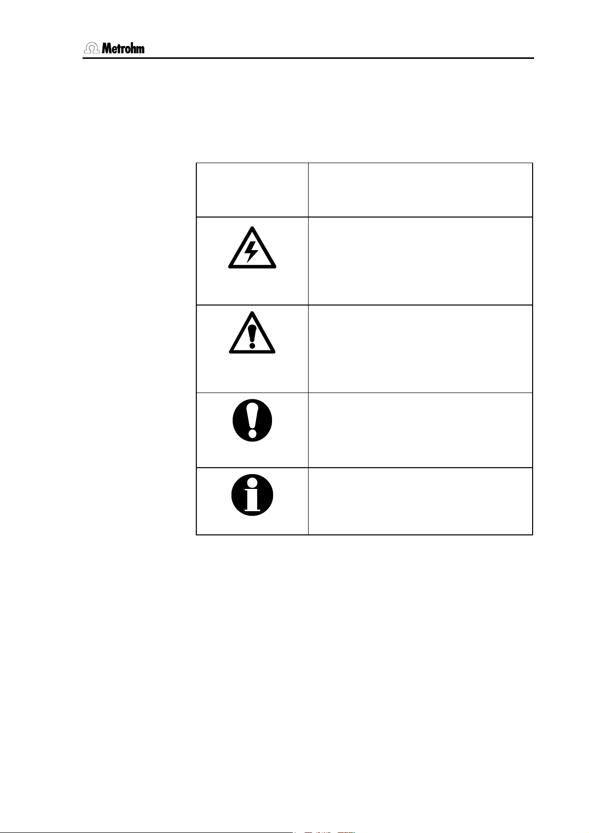
The following notations and pictograms are used in these instructions:
35 Operating element
The operating elements are explained on
pages 4ff.
Danger
This symbol indicates a possible risk of
death or injury to the user and possible
damage to the instrument or its components by electricity.
Danger/Warning
This symbol indicates a possible risk of
death or injury to the user and possible
damage to the instrument or its components.
Attention
This symbol indicates important information. Read the information provided before
you continue.
Information
This symbol indicates additional information
and tips which may be of particular use to
you.
824 Easy Sample Changer, Introduction 3
Page 10
1.3 Parts and controls
1.3 Parts and controls
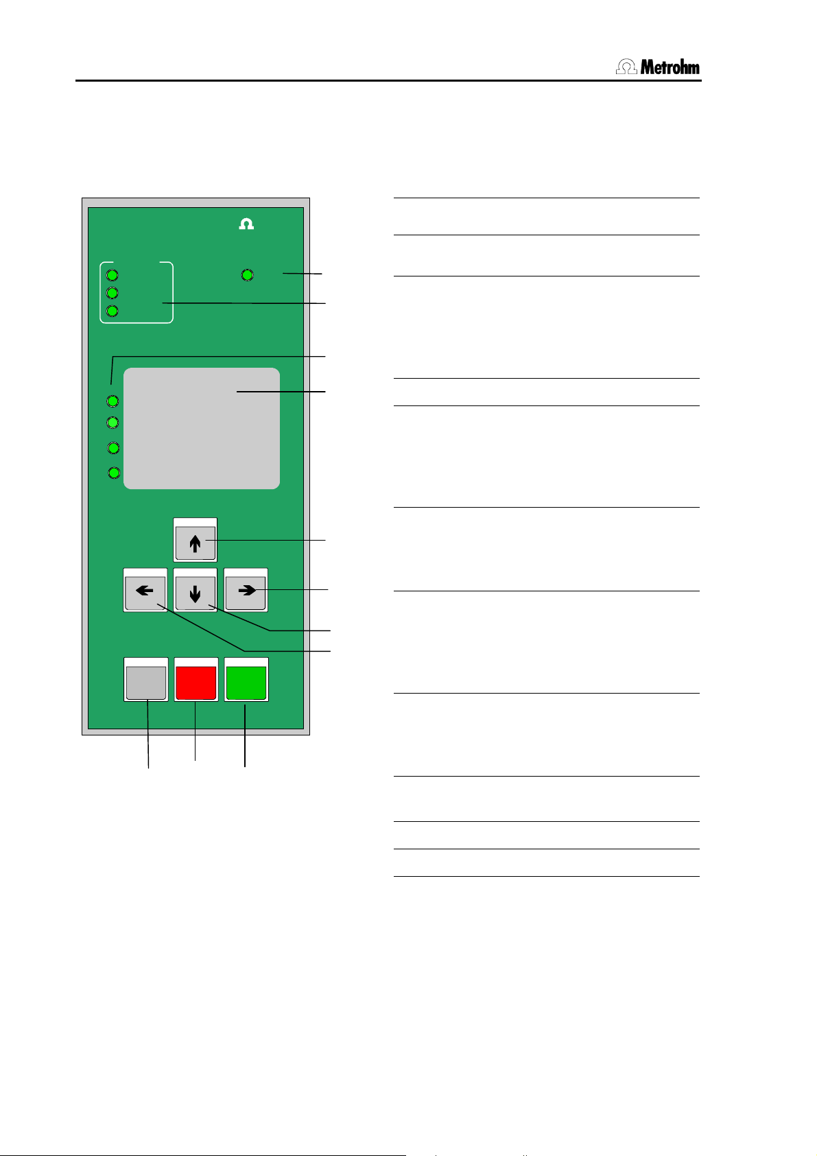
1.3.1 The keypad
1 Status LED
Easy Controller
SELECT
Method
PUMP/STIR
Config
Methods
1 ________________________
2 ________________________
3 ________________________
4 ________________________
STIR 1
PUMP 1 PUMP 2
STIR 2
Met ro h m
Status
2
3
4
5
6
2 SELECT LEDs
Indicate the user mode
3 LEDs 1 to 4
• Method selection
• Stirrer/Pump status
• Configuration steps
• Error display
4 Labeling field for methods
5 Arrow key up / Stirrer 1
• Lift up
• Method selection
• Stirrer 1 on/off
• Sets lift position and stirrer rate
6 Arrow key right / Pump 2
• Rotates rack clockwise
• Pump 2 on/off
• Next configuration step
7 Arrow key down / Stirrer 2
HOLD STOP
6.2142.110
9
Fig. 1 Keypad
RESETSELECT
10
START
11
7
8
• Lift down
• Method selection
• Stirrer 2 on/off
• Sets lift position and stirrer rate
8 Arrow key left / Pump 1
• Rotates rack counterclockwise
• Pump 1 on/off
• Previous configuration step
9 User mode / Interrupt method /
Acknowledge error message
10 Initialize changer / Cancel method
11 Start method / Continue method
4 824 Easy Sample Changer, Introduction
Page 11
1.3 Parts and controls
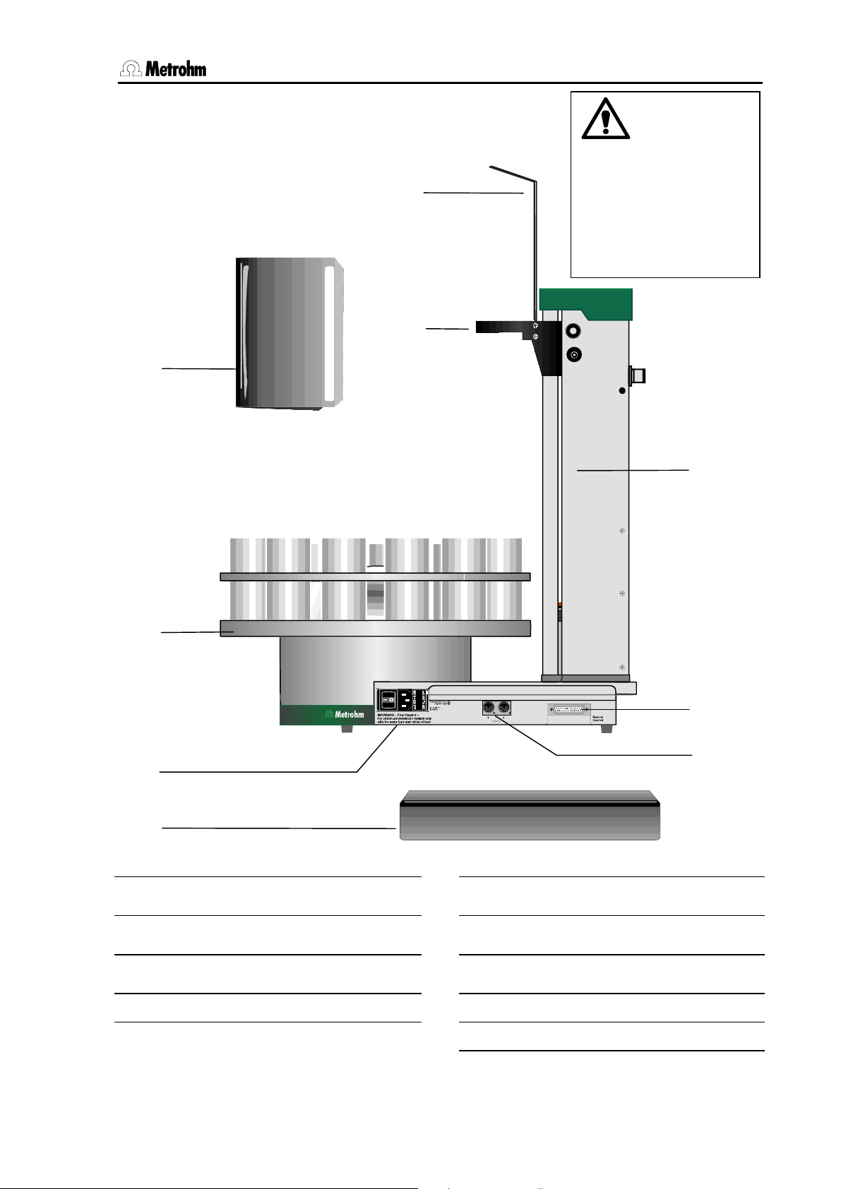
1.3.2 Individual parts and standard accessories
12
14
13
The 824 Easy Sample
Changer must not be
operated without the
splash protector 13 and
connections cover 17 in
position.
18
15
19
20
16
17
Fig. 2 Side view of 824 Easy Sample Changer
12 Tubing guide 16 Mains switch and fuse holder
13 Splash protector 6.2751.010 17 Connections cover 6.2752.010
14 Lift 18 Tower
15 Sample rack e. g. 6.2041.310 19 Remote interface
20 Stirrer connection
824 Easy Sample Changer, Introduction 5
Page 12

1.3 Parts and controls
21
Ext.
Ext.
Pump 1
Pump 2
22
16 V
16 V
max. 300 mA
max. 300 mA
25
Line sleeve
21
Pump connectors
22
Manufacturing number
23
RS 232 Keybo ard
Made by Metrohm Herisau Switzerland
Fig. 3 Rear view
24
25
Type 1.824.0010 Nr.
0010/01104
Keyboard connector
RS232 connector
23
24
6 824 Easy Sample Changer, Introduction
Page 13
1.4 Safety information
1.4 Safety information
Warning!
This instrument should only be used in accordance with the information
given in these Instructions for Use.
1.4.1 General:
This instrument left our works in perfect condition from the point of view
of its operational safety (see Technical data, safety specification). To
keep it in this condition and to continue to operate safely the following
information must be carefully observed.
1.4.2 Electrical safety
Please observe the following guidelines:
• Only qualified Metrohm personnel should carry out service work on
electronic components.
• Do not open the instrument housing as this could damage the in-
strument. The housing contains no components which could be
serviced or exchanged by the user.
Electrical safety when handling the instrument is guaranteed within the
scope of Standard IEC 61010-1. However, please observe the following
point:
Protection against electrostatic charges
Warning!
Electronic components are sensitive to electrostatic charges and can
be destroyed by a discharge. Always remove the mains connection
cable from socket 12 before making or breaking electrical connections
on the rear panel of the instrument.
Connection to the electricity supply:
This instrument must only be operated at the specified mains voltage.
Repair and maintenance:
If faults or malfunctions occur while using the 824 Easy Sample
Changer we recommended that you first check that the connection to
the control instrument has been made correctly.
The instrument must not be opened. This is reserved exclusively for
authorized service personnel.
824 Easy Sample Changer, Introduction 7
Page 14
1.4 Safety information
2 Installation
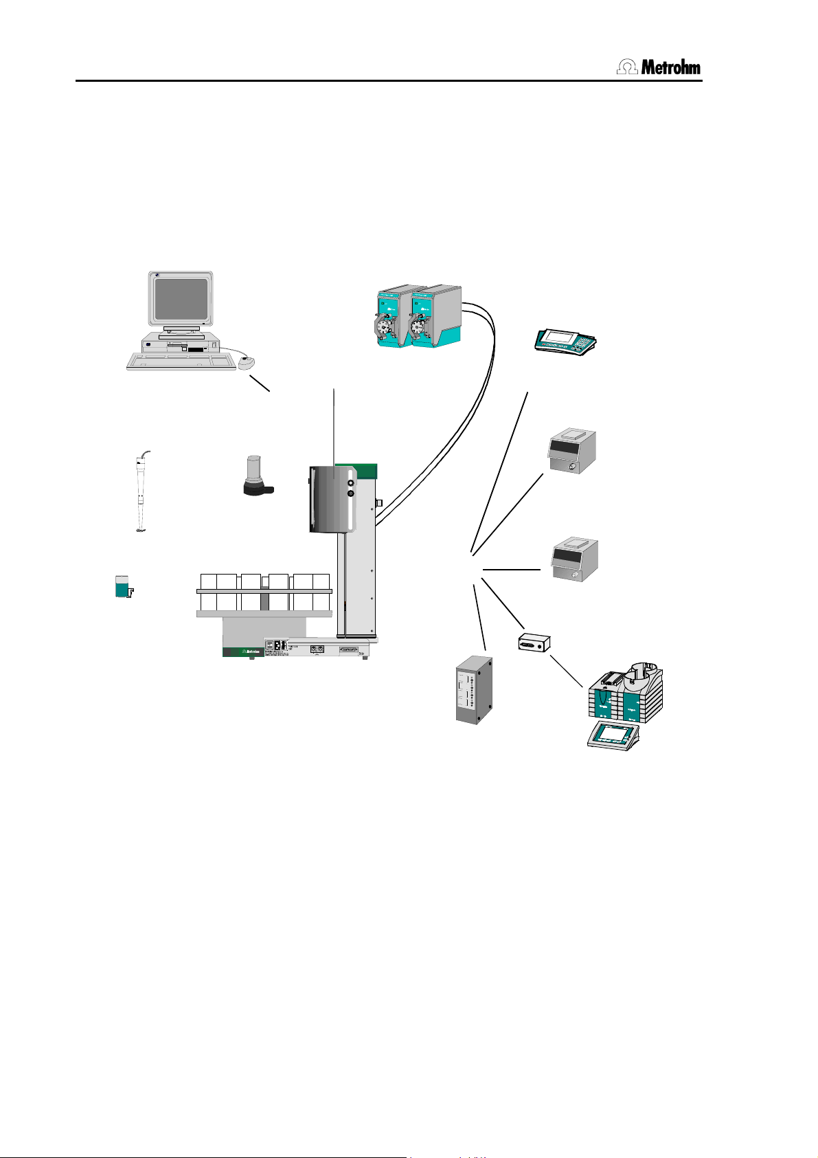
This section describes the things you should pay attention to when unpacking and starting up the 824 Easy Sample Changer. It also tells you
how a complete automation system is built up.
The following illustration provides an overview of the peripheral devices
which can be attached to an 824 Easy Sample Changer:
691
780
692
781
712
713
665
725
765
775
776
Personal Computer
759 Swing Head
RS232
772 Pump Unit
pH Meter / Ion meter
Conductometer
Dosimat
722/802 Rod stirrer
741 Magnetic stirrer
824 Easy Sample Changer
Remote
Remote Box MSB
731 Relay Box
Fig. 4 824 Easy Sample Changer – peripheral devices
7xx
Titrino
family
808/809
Titrando
8 824 Easy Sample Changer, Installation
Page 15
2.1 Instrument setup
2.1 Instrument setup
2.1.1 Packaging
The 824 Easy Sample Changer and its specially packed accessories
are supplied in very protective special packaging. Please store this
packaging in a safe place; it is the only way in which the safe transport
of the instrument can be guaranteed.
2.1.2 Checks
Please check that the delivery is complete and undamaged immediately on receipt (compare with delivery note and list of accessories
given in Section 8.6). If transport damage is evident please refer to the
information given in Section 8.8.1 ''Warranty'.
2.1.3 Location
The 824 Easy Sample Changer has been developed for indoors use
and must not be used in explosion-endangered surroundings.
Place the instrument on a suitable vibration-free laboratory bench, protected as much as possible from corrosive atmospheres and contamination by chemicals.
Select a location in which the ambient temperature is normally between
+5 °C and +45 °C. The instrument should be protected against excessive variations in temperature and direct sunshine.
If an instrument which has been stored under cold conditions is
brought into a warm room then the atmospheric humidity may condense inside the instrument and form water. In order to avoid damaging
the instrument please wait for at least one hour before switching it on.
2.2 Mains connection
Please observe the following rules when connecting the instrument to
the electricity supply. If the instrument is operated with an incorrectly set
mains voltage and/or an incorrect mains fuse then it represents a fire
hazard!
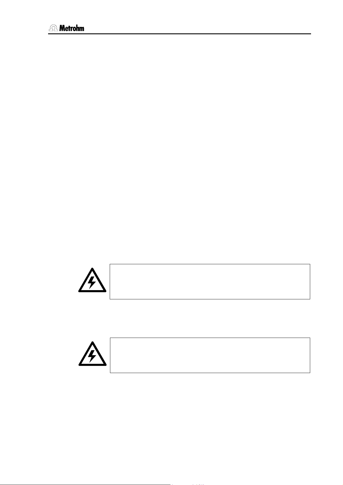
Setting the mains voltage
Before you switch on the 824 Easy Sample Changer for the first time
please check that the mains voltage set on the instrument (see illustration on the following page) corresponds to your local mains voltage. If
this is not the case then you must alter the mains voltage as follows:
824 Easy Sample Changer, Installation 9
Page 16
2.3 Keyboard connection
• Pull out mains cable
Remove the mains cable from the mains supply connection of the 824
Easy Sample Changer.
• Remove the fuse holder
Use a screwdriver to loosen the fuse holder beside the mains supply
connection and remove it completely.
• Check the fuse and replace it
Carefully remove the built-in fuse for the intended voltage from the fuse
holder and check its specifications (the position of the fuse in the fuse
holder is indicated by the white arrow beside the voltage range):
100…120 V 0.5 A (slow blow) Metrohm-No. U.600.0014
220…240 V 0.25 A (slow blow) Metrohm No. U.600.0011
• Insert fuse
Exchange the fuse if necessary and replace it in the fuse holder.
• Insert fuse holder
Depending on the required mains voltage, insert the fuse holder so that
the white arrow of the corresponding voltage range points to the white
bar; this is to the right of the fuse holder (see below).
220 – 240 V
100
-
120 V
240 V
-
220
100 – 120 V
220
-
240 V
120 V
-
100
Fig. 5 Fuse holder
Mains switch
Mains connection
Fuse holder
• Attach connections cover
Position the connections cover in the guide rail above the connections
strip. The connections cover protects the connections from spilt chemicals.
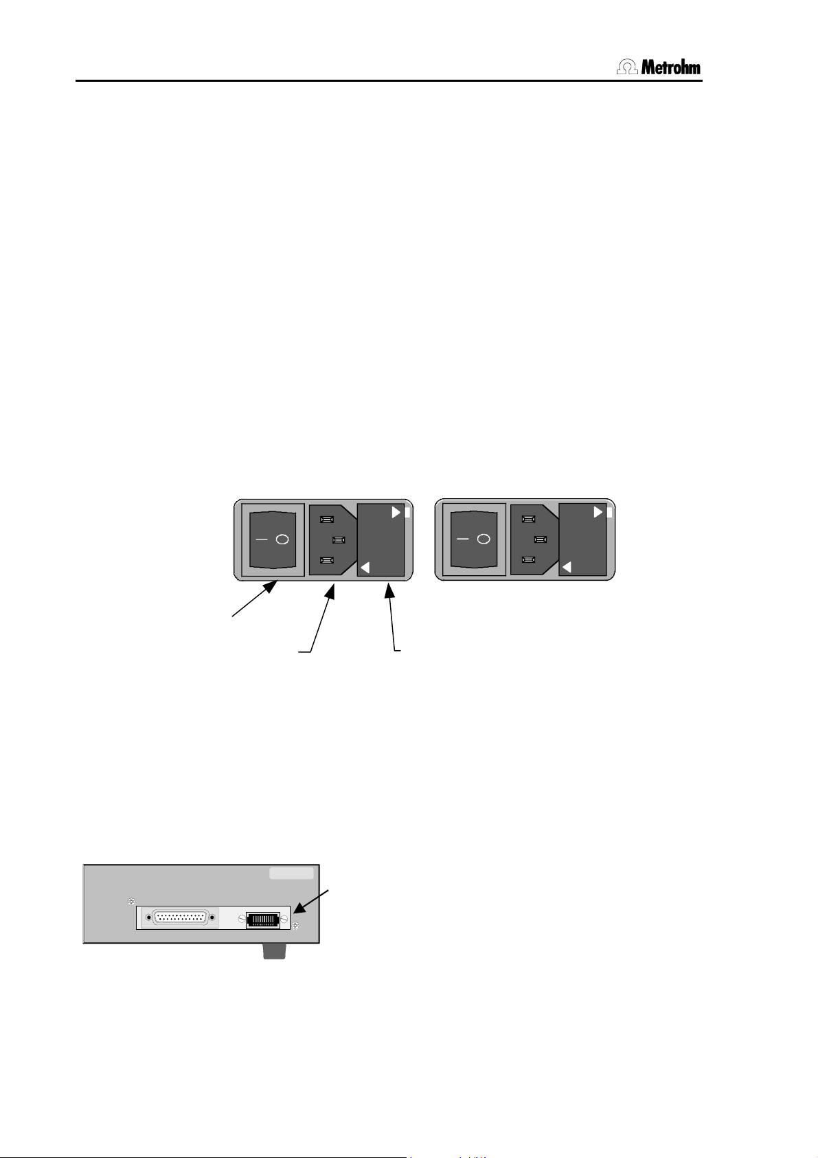
2.3 Keyboard connection
Type 1.824.0010 Nr.
RS 232 Keyboard
Made by Metrohm Herisau Switzerland
Fig. 6 Rear panel of instrument
10 824 Easy Sample Changer, Installation
0010/01104
The keyboard is attached to the connection 24
provided for it on the rear panel of the instrument. To
remove the connection press both sides of it together.
Page 17
2.4 Attaching and equipping a titration head
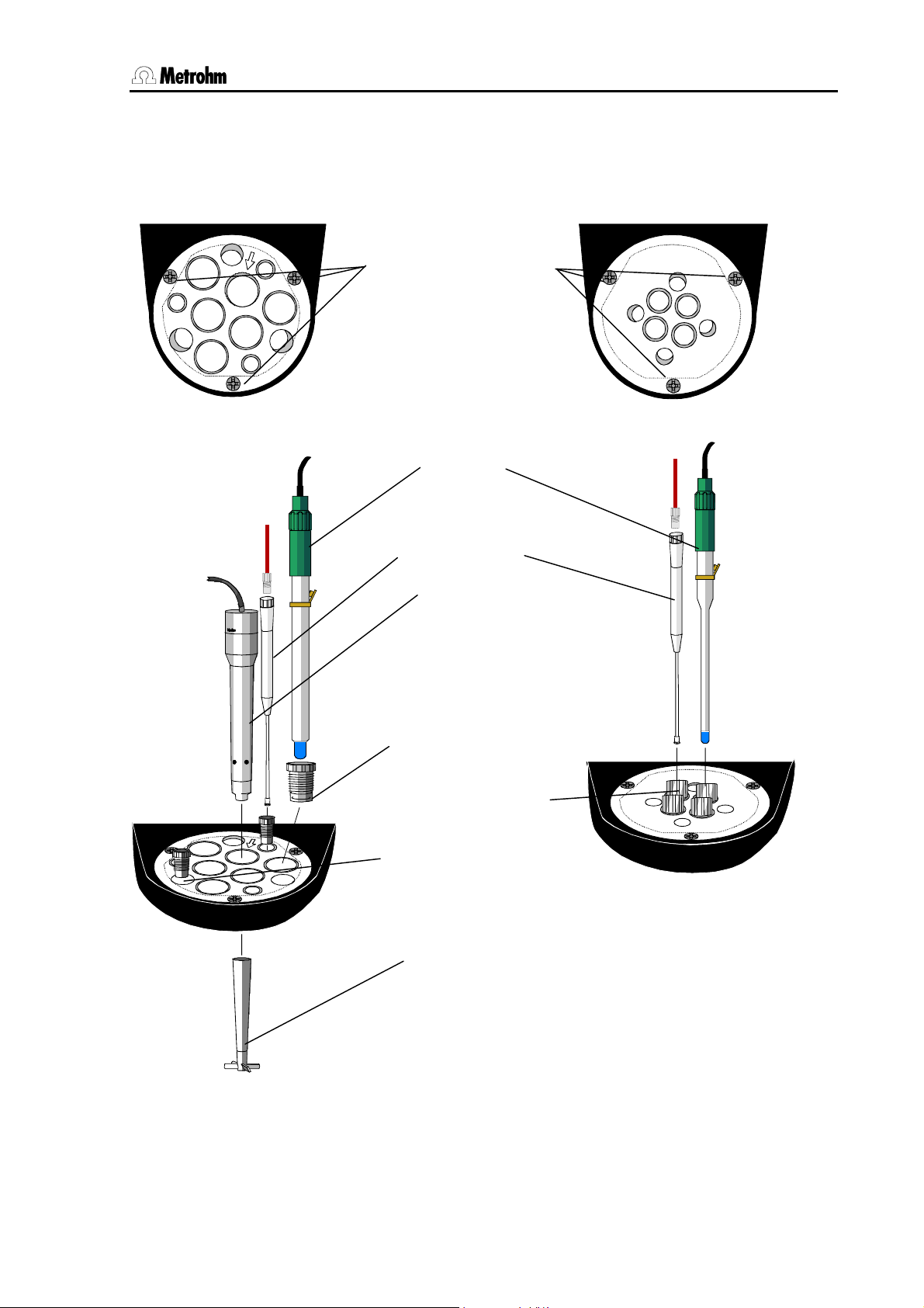
2.4 Attaching and equipping a titration head
Macro-titration head
6.1458.010
Attachment screws
SGJ14 Sleeve
SGJ9 Guiding sleeve
Propeller stirrer
Fig. 7 Macro-titration
Note about the Macro-titration head
Micro-titration head
Electrode
Buret tip
Rod stirrer
2.802.0020
6.1236.020
Screw nipple
4.658.0180
6.2709.070
6.1909.020
head
6.1458.020
Fig. 8 Micro-titration head
Only special micro-electrodes
can be used with the microtitration head; see list of
accessories, p. 46.
The SGJ14 opening marked by an arrow is bored at a slight angle so that a rod stirrer or an
electrode can be centered in narrow titration vessels.
824 Easy Sample Changer, Installation 11
Page 18
2.4 Attaching and equipping a titration head
A
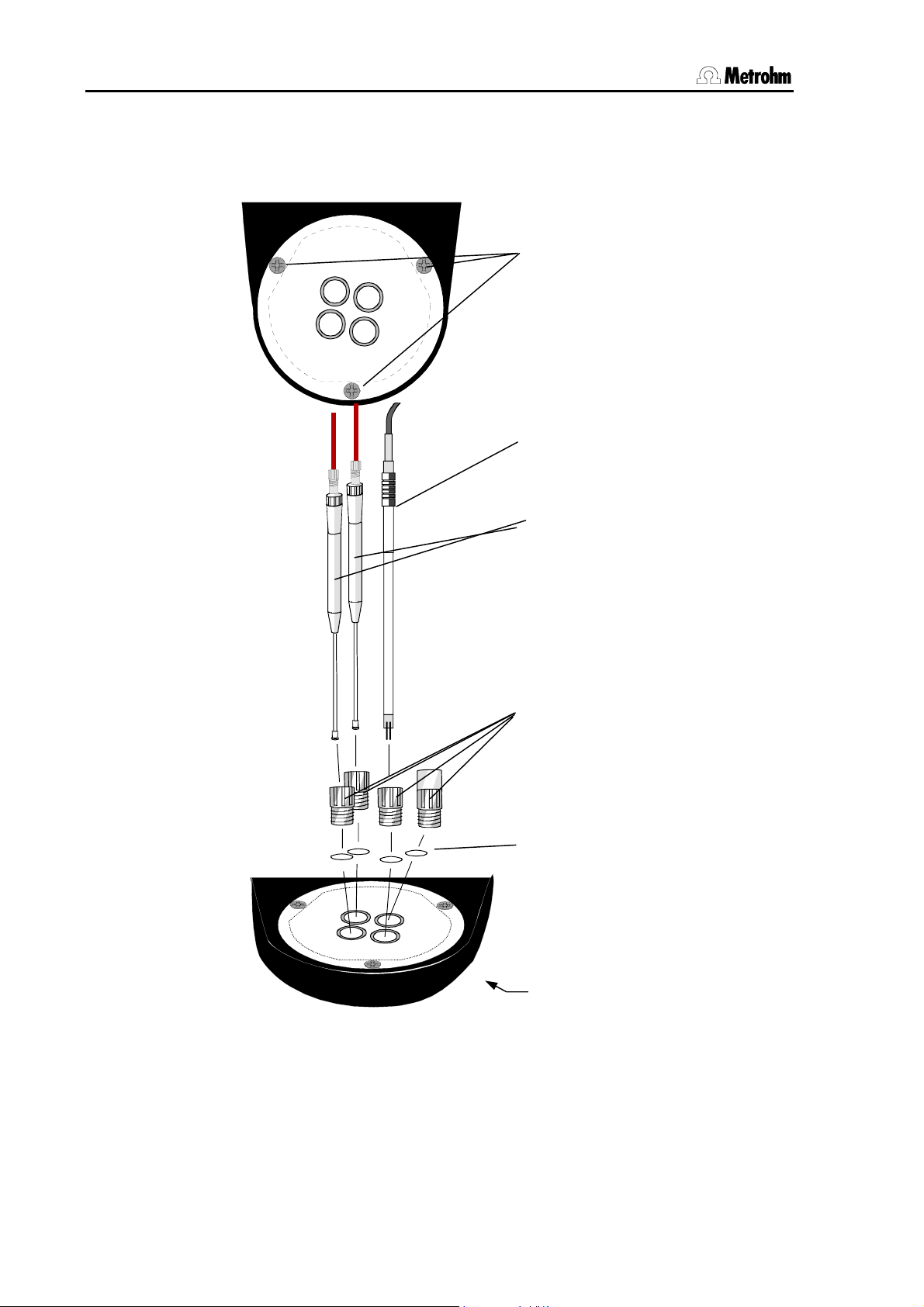
2.4.1 Attaching and equipping the KF titration head
KFT Titration head
6.1458.030
ttachment screws
Double Pt-electrode
6.0340.000
Buret tips
6.1543.200
Screw nipple
4.658.0180
O-Rings
E.301.0022
O-Ring (below)
E.301.0080
Fig. 9 KF Titration head
Note:
In order to ensure an optimal seal of the titration vessel the M10 threads
should be inserted into the titration head together with the O-rings.
12 824 Easy Sample Changer, Installation
Page 19
2.4 Attaching and equipping a titration head
When attaching the tubing and cable connections these should be led
from the titration head through the tubing guide in order not to restrict
the range of movement of the lift. Take care that the tubing is long
enough to accommodate the whole range of movement of the lift.
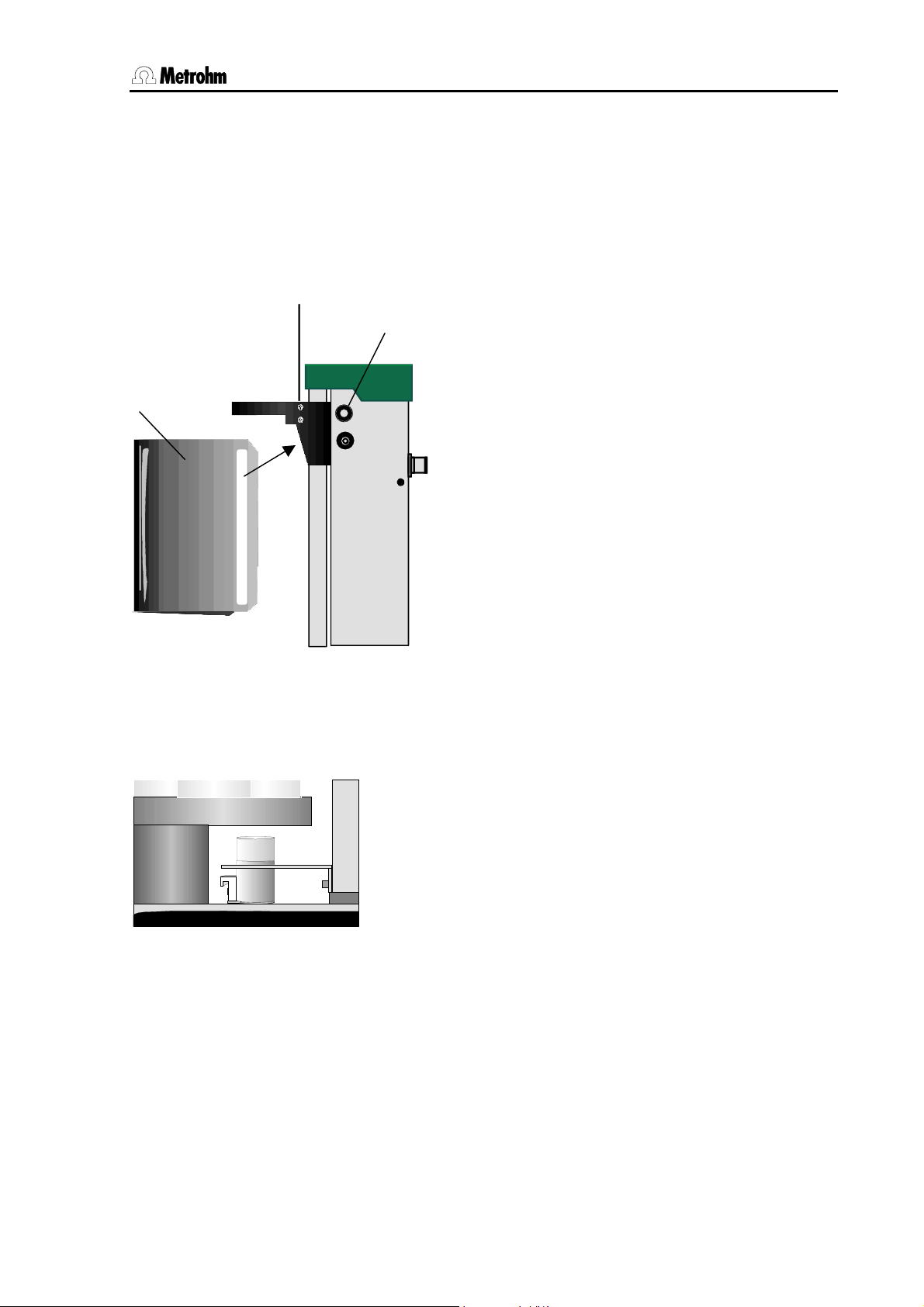
2.4.2 Attaching the splash protector
For safety reasons the 824 Easy Sample Changer should not be operated unless the splash protector is in its proper position.
13
Fig. 10 Attaching the splash protector
2.4.3 741 Magnetic Stirrer
Fig. 11 Attaching the magnetic stirrer
26
• On both sides of the tower loosen knurled nuts
26.
• Slip the slot-shaped openings of the splash
protector 13 over the attachment screws and
tighten up knurled nuts 26 again.
• If the knurled nuts 26 are loosened slightly it is
easy to adjust the height of the splash protector
13.
Apart from the micro-titration head, the
2.824.020 version also includes a 741 Magnetic
Stirrer.
The use of the 741 Magnetic Stirrer is particularly
recommended for Karl Fischer titrations.
The 2.741.0010 Magnetic Stirrer can be attached
to the tower by using the holder (6.2034.020)
and supplied screws as shown in the drawing
alongside.
824 Easy Sample Changer, Installation 13
Page 20
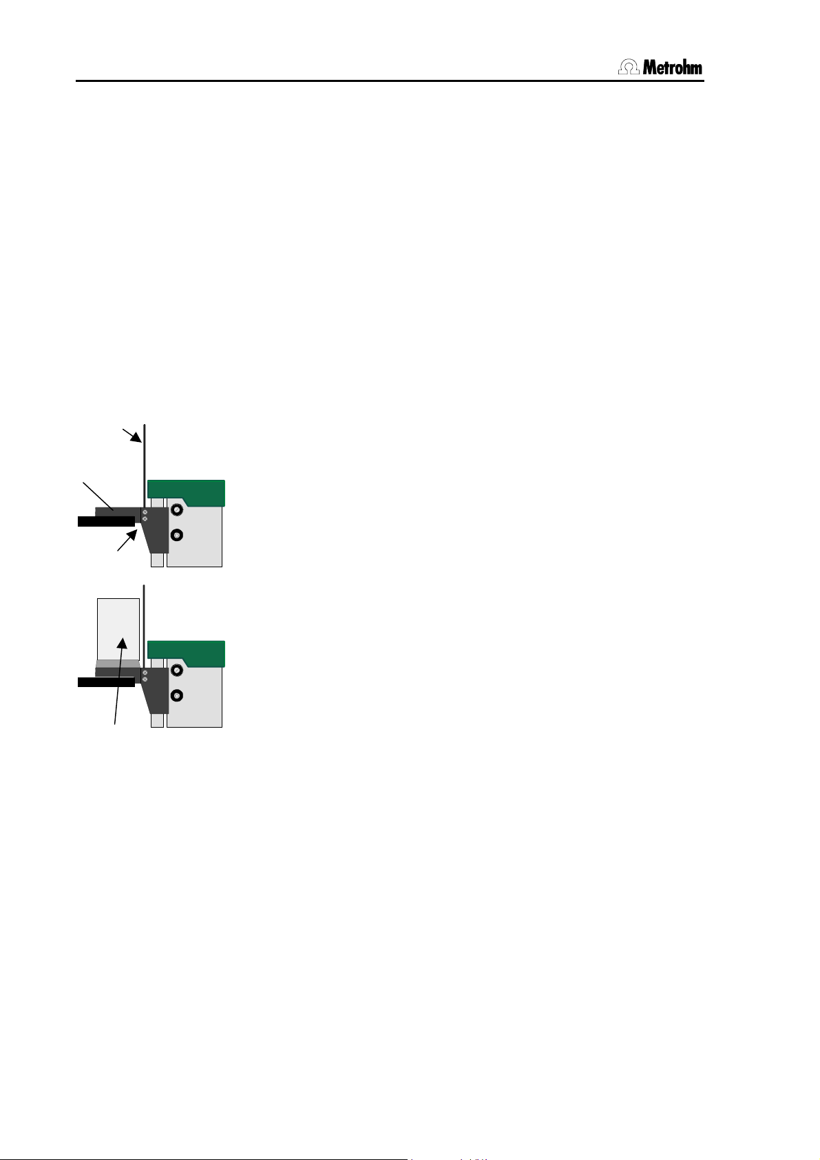
2.5 Attaching the 759 Swing Head
2.5 Attaching the 759 Swing Head
In order to accurately move to the individual sample vessels when multirow sample racks are used (see p. 19), the 759 Swing Head can be
used instead of a normal titration head. It is equipped with either a titration head (Model 2.759.0020) or with a transfer head (Model
2.759.0010).
The 759 Swing Head with titration head can be used with the 2-row
sample rack M48-1. The swing head version with the transfer head is intended for use with the 3-row sample racks M128-2, M129-2 and M142-
2.
2.5.1 Procedure
• Switch off instrument.
12
• Remove the titration head 14 by loosening the four screws on both
the outer sides of the lift.
14
Loosen
759 Swing
Head
Fig. 12
Attaching the 759
Swing Head
• Screw off the tubing guide from the titration head 14.
• Attach the new titration head (6.1462.020) or the transfer head
(6.1462.010) to the bottom of the swing head by using the three
screws provided.
• Screw the tubing guide 12 onto the new titration or transfer head.
• Attach new titration or transfer head to the lift and fasten it with the
four screws.
• Connect the 759 Swing Head to the Remote socket 19 of the 824
Easy Sample Changer, see also p. 17.
• Place a multi-row sample rack on the turntable of the sample
changer.
• Switch on instrument.
• If the swing head moves when the instrument is switched on then
this means that it has been recognized by the 824 Easy Sample
Changer and is ready for use.
• If the swing head does not move when the instrument is switched on
then switch the instrument off and then on again.
14 824 Easy Sample Changer, Installation
Page 21
2.6 Connecting devices to the Remote socket
2.6 Connecting devices to the Remote socket
Connection cable
If the 824 Easy Sample Changer is to be connected to other devices
then only Metrohm cables should be used as these are the only cables
that guarantee perfect data transfer.
Note:
The Remote cable for the 824 Easy Sample Changer have a marking at
each end which indicates the instrument for which the particular end is
intended to be used and the connection to which it is to be connected.
Example (standard Remote cable):
Titrino B
692 / 712 / 713
Before peripheral devices are connected the sample changer must be
switched off as otherwise the instruments could be damaged.
2.6.1 Remote connections
Sample changer — Titrino
with standard cable
824
Fig. 13 Connecting a 7xx Titrino
Cable 6.2141.020
B
A
Titrino
C
D
824 Easy Sample Changer, Installation 15
Page 22

2.6 Connecting devices to the Remote socket
Sample changer — Titrando
with standard cable and 6.2148.010 Remote Box
Remote box
6.2148.010
MSB 3
MSB 1
MSB 4
MSB 1
824
MSB
808 / 809 Titrando
6.2141.020 Cable
Fig. 14 Connecting an 8xx Titrando
Sample changer — Titrino — 765/776 Dosimat
B
A
Titri no
824
C
D
6.2141.040 Cable
A
665
D
B
C
Fig. 15 Connecting a Titrino and Dosimat
16 824 Easy Sample Changer, Installation
Page 23

2.6 Connecting devices to the Remote socket
Sample changer — 780/781 pH-Meter
with standard cable and 6.2148.010 Remote box
Remote box
6.2148.010
824
6.2141.020 Cable
MSB
Fig. 16 Connecting a 780/781 pH Meter
Sample changer with 759 Swing Head
824
Connecting further devices via
Remote cables
Fig. 17 Connecting the 759 Swing Head
The swing head is connected to the Remote interface of the 824 Easy
Sample Changer. The connection of the 759 Swing Head allows the
connection of further devices via Remote lines; 4 lines (Input 7 and
Output 11–13) are occupied by the swing head. These four lines are not
led any further through the connection.
824 Easy Sample Changer, Installation 17
Page 24

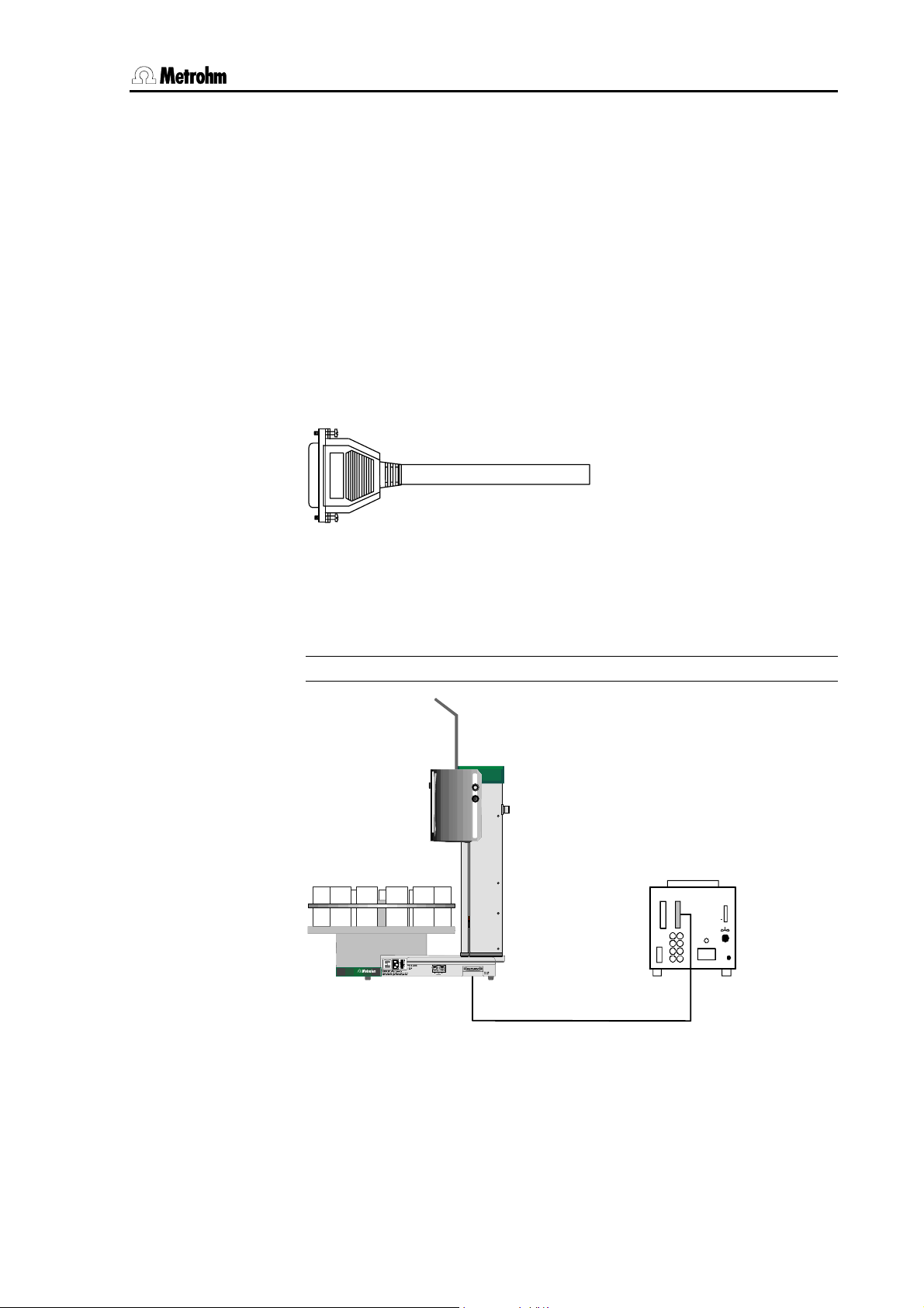
2.7 Serial connection (RS232)
2.7 Serial connection (RS232)
A personal computer can be connected to the serial RS232 interface
25. In this way the 824 Easy Sample Changer can be remotely controlled (in the same way as the Metrohm 730 Sample Changer), provided that a suitable software such as Tinet 2.5 is installed.
824
Fig. 18 Connecting a computer
A requirement for correct data transfer is that the transmission parameters are correctly set; these must correspond to the settings at the interface of the connected device.
The standard transmission parameters for the 824 Easy Sample
Changer are:
Baud Rate: 9600 Baud
Data Bit. 8
Stop Bit: 1
Parity: none
Handshake: HWs
Cable 6.2125.060 (25p/25p)
oder 6.2125.110 (25p/9p)
18 824 Easy Sample Changer, Installation
Page 25

2.8 Sample racks
2.8 Sample racks
A sample rack is a turntable which accommodates sample vessels and
which is placed on the sample changer. As in titrations or measurements various sizes of sample vessels are normal or necessary, different types of easily exchangeable sample racks can be used. The number of sample vessels which can be accommodated on a sample rack
depends on their diameters.
When used with the 824 Easy Sample Changer the highest rack position is intended to be used for a special beaker for rinsing or conditioning/dipping.
Metrohm supplies the following standard sample racks:
Type No. of
samples
M12-0 12 250 mL Metrohm titration beaker 000001 6.2041.310
M16-0 16 150 mL beaker 000010 6.2041.320
M24-0 24 75 mL Metrohm titration beaker 001000 6.2041.340
M12-0 12 150 mL beaker or
M14-0 14 200 mL disposable beaker (Euro) 000011 6.2041.370
M14-0 14 8 oz disposable beaker (US) 000101 6.2041.380
M16-0 16 120 mL disposable beaker (US) 100001 6.2041.390
Sample racks for use with the 759 Swing Head:
M48-1 48 * 75 mL Metrohm titration beaker 010000 6.2041.350
M128-2 128 15 mL test tubes+
M142-2 142 15 mL test tubes +
M129-2 129 11 mL test tubes +
*Special beaker at position 24
Type of sample vessel Predefined
magnet code
100000 6.2041.360
200 mL disposable beaker (Euro)
000110 6.2041.400
2 x 250 mL titration beaker
001010 6.2041.410
1 x 500 mL beaker
010001 6.2041.430
2 x 300 mL beaker
Ordering
number.
Each sample rack is unambiguously identified by a magnet code. Magnetic pins, attached to the base of the rack, provide a 6-place binary
code. This means that the magnet sensor can automatically recognize
the rack that is attached when the first beaker position is in front of the
tower.
824 Easy Sample Changer, Installation 19
Page 26

2.8 Sample racks
2.8.1 Positioning a sample rack
After a sample rack has been positioned the sample changer must be
initialized with <RESET> so that the
Magnet holder
Magnet sensor
magnet code of the rack can be read
in. This makes the unambiguous recognition of the rack possible and
therefore the correct positioning of the
beakers.
Fig. 19 Attaching a sample rack
20 824 Easy Sample Changer, Installation
Page 27

3.1 The <SELECT> key
3 Operation
This section contains the basic principles for using the 824 Easy Sample Changer.
As well as processing a series of samples automatically, the 824 Easy
Sample Changer can also be operated manually in order, for example,
to rinse the electrode in a special beaker during the preparation of a series of samples.
In order to load methods or use functions which are not available in the
normal operating status the <SELECT> key must be activated.
3.1 The <SELECT> key
SELECT
HOLD
<SELECT>
<SELECT>
<SELECT>
<SELECT>
The <SELECT> key is used to switch between the different operating
levels of the 824 Easy Sample Changer. Each pressure on the key
SELECT
Met ho d
PUMP/STIR
Conf ig
SELECT
Met hod
PUMP/STIR
Conf ig
SELECT
Met ho d
PUMP/STIR
Conf ig
SELECT
Met ho d
PUMP/STIR
Conf ig
switches from one mode to the next. The LEDs (see left) indicate the
selected mode.
The individual modes and their functions are as follows:
• Normal operating mode
o Controls the lift and the sample rack.
o Starts a method.
• Method selection
o Selects one of four predefined basic methods or modified meth-
ods
• Pump and stirrer control
o Switches two external pumps on/off
o Switches stirrer 1 and 2 on/off
• Sample changer settings
o Sets the lift working height
o Sets the rinsing height of the lift
o Sets the shifting position of the lift
o Sets the stirring rate
SELECT
Met ho d
PUMP/STIR
Conf ig
<SELECT> returns to the normal operating mode.
824 Easy Sample Changer, Operation 21
Page 28

3.2 Settings
3.2 Settings
In order to be able to work comfortably with the 824 Easy Sample
Changer a few settings must first be made.
• The various lift settings depend on the rack used; this means that
they must be made for each sample rack according to the size of the
sample vessels used.
• The stirrer rate is method-specific and is stored in the active method.
If you use different methods then the stirrer speed must be optimized
separately for each method.
3x
HOLD
SELECT
SELECT
Met ho d
PUMP/STIR
Conf ig
Place a sample rack on the turntable and press <STOP/RESET>.
Place a filled sample beaker at the rack position in front of the lift in
order to make the following settings.
Press the <SELECT> key three times.
The SELECT LEDs show that the 824 Easy Sample Changer is now in
the configuration mode.
You can now use the <Í> and <Î> keys to switch between the four
possible settings in this mode.
3.2.1 Setting the working position of the lift
1
2
3
4
STIR 1
STIR 2
The lift with the titration head can be easily moved up and down with
the <Ï> and <Ð> keys respectively.
Set the working height of the lift so that the electrode is immersed and
the stirrer can work efficiently.
Accept/ continue with <Î>.
3.2.2 Setting the rinsing position of the lift
1
2
3
4
STIR 1
STIR 2
The lift with the titration head can be easily moved up and down with the
<Ï> and <Ð> keys respectively.
If standard method 4 is used then the rinsing position of the lift is
required for aspirating the used sample. Set the rinsing position of the
lift so that the sample vessel can be emptied completely. A rinsing
position which is lower than the working height can be selected. The
mounting position of the aspiration tubing can be selected as required.
Accept/ continue with <Î>.
22 824 Easy Sample Changer, Operation
Page 29

3.2 Settings
3.2.3 Setting the shifting position of the lift
1
STIR 1
2
3
4
STIR 2
The lift with the titration head can be easily moved up and down with the
<Ï> and <Ð> keys respectively.
Set the shift height of the lift so that the sample rack can rotate freely.
The electrode must fully emerge from the sample beaker.
Accept/ continue with <Î>.
3.2.4 Setting the stirrer rate
1
2
3
4
STIR 1
STIR 2
The stirrer rate (applies to both stirrer outputs) can be easily increased
or reduced in 15 steps with the <Ï> and <Ð> keys respectively.
The standard setting is step 3.
Accept/ continue with <Î>.
824 Easy Sample Changer, Operation 23
Page 30

3.3 Manual operation
3.3 Manual operation
When it has been switched on the 824 Easy Sample Changer is in the
normal operating mode. The most important functions for manual operation can be carried out by pressing a key.
3.3.1 Moving the lift
In normal operating
mode
STIR 1
STIR 2
The lift with the titration head can be easily moved up and down with
the <Ï> and <Ð> keys respectively.
Please note that the lift must be located above a valid rack position. If,
because of a possible mechanical influence, the rack is no longer in its
correct position then press the <RESET/STOP> key.
3.3.2 Rotating the sample rack
In normal operating
mode
PUMP 1
PUMP 2
The sample rack can be rotated counterclockwise with the <Í> key
and clockwise with the <Î> key.
For safety reasons the lift must be at or above the set rotating position
when the rack is rotated, so first move the lift upward or press the
<RESET/STOP> key.
3.3.3 Switching the stirrer on/off
2x <SELECT>
STIR 1
STIR 2
After the <SELECT> key has been pressed twice the <STIR 1> and
<STIR 2> keys can be used to switch the stirrers on and off. The
stirring rate of both stirrers can first be set under 'SELECT / Config’, see
below.
LEDs LED 1 and LED 2 show the status of stirrer connections 1 and 2
respectively (LED lit up = on).
3.3.4 Operating the pumps
2x <SELECT>
PUMP 1
PUMP 2
After the <SELECT> key has been pressed twice the pump connections 1 and 2 (each ±16 V) can be switched on and off with the
<PUMP 1> and <PUMP 2> keys respectively.
LEDs LED 3 and LED 4 show the status of pump connections 1 and 2
respectively (LED lit up = on).
24 824 Easy Sample Changer, Operation
Page 31

3.4 Automatic operation
3.4 Automatic operation
3.4.1 Preparing a sample series
• Prepare all the samples to be processed. Select the sample vessel
size according to your type of sample rack. The setting for the predefined lift position must be matched to the size of your sample
vessels.
• Place the sample vessels on the rack. Start with rack position 1.
• Do not forget to place a rinsing/conditioning beaker at the highest
rack position. Most sample changer methods require a special
beaker, see method description p. 29ff.
In order to process a series of samples a suitable method must first be
loaded, see below.
3.4.2 Method selection
1x <SELECT>
STIR 1
3x <SELECT>
STIR 2
After pressing the <SELECT> key a method can be selected by using
the <Ð> and <Ï> keys. Four predefined simple standard methods are
available (Methods 1,2,3 and 4).
LEDs LED 1 to 4 show the selected method. The selected method is
accepted with <SELECT>.
Return to the normal operating mode with 2x <SELECT>.
3.4.3 Starting a method
A method is started with the <START> key.
START
• When a method is started the sample changer is first initialized, i.e.
the lift is moved upward as far as it will go and the sample rack is
moved to the starting position. The magnet code of the rack is read
in and the corresponding rack table, in which the beaker positions
on the rack are defined, is loaded.
• While the method is running the status LED blinks slowly (once per
second).
• After the start of the method the starting sequence is carried out
once. This contains commands for preparing for a series of samples.
• When all rack positions have been processed the final sequence is
carried out.
824 Easy Sample Changer, Operation 25
Page 32

3.4 Automatic operation
3.4.4 Interrupting a method run
SELECT
HOLD
Press the <HOLD> key to briefly interrupt a method run.
• In the HOLD condition the status LED blinks more quickly.
• The run can be continued from the same position by pressing the
<START> key.
3.4.5 Canceling a method run
RESET
STOP
A method run is canceled with the <STOP> key.
• The sample changer switches back to the normal operating mode.
The status LED lights up permanently.
• After the manual cancelation of a method the final sequence is not
carried out.
26 824 Easy Sample Changer, Operation
Page 33

3.5 Functions of the LEDs
3.5 Functions of the LEDs
The 824 Easy Sample Changer has several green LEDs (LED) which indicate the status of the instrument.
3.5.1 The Status LED
Status
Status LED 1 shows the complete status of the sample changer.
The LED lights up… when the 824 Easy Sample Changer is in the normal operating
mode.
The LED does not light up… when a fault has occurred.
The LED blinks slowly… while a method is running.
The LED blinks quickly… when the 824 Easy Sample Changer is in the HOLD condition. An
interrupted method can be continued with <START> or canceled
with <STOP>.
3.5.2 The [SELECT] LEDs
SELECT
Met ho d
PUMP/STIR
Conf ig
’Method’ LED lights up… during the selection of a method.
‘PUMP/STIR’ LED lights up … when the external pumps and stirrers are being operated
‘Config’ LED lights up … when setting the lift positions and the stirrer rate.
The LEDs in the [SELECT] field indicate the status when the settings
are changed.
manually.
3.5.3 LEDs 1 to 4
Depending on the instrument mode, LEDs 1 to 4 have different functions.
In the normal operating mode
Shows the active method.
During method selection
Shows the method to be loaded from the method memory.
824 Easy Sample Changer, Operation 27
Page 34

3.5 Functions of the LEDs
During manual operation
Shows the switching status of the pumps and stirrers.
LED 1 : lights up when Stirrer 1 is running
LED 2 : lights up when Stirrer 2 is running
LED 3 : lights up when Pump 1 is running
LED 4 : lights up when Pump 2 is running
During the configuration of the sample changer settings
Shows the possible settings.
LED 1 : lights up when setting the working position of the lift
LED 2 : lights up when setting the rinsing position of the lift
LED 3 : lights up when setting the shifting position of the lift
LED 4 : lights up when setting the stirrer rate
28 824 Easy Sample Changer, Operation
Page 35

4.1 Information about the methods
4 Standard methods
On delivery the 824 Easy Sample Changer already contains four optimized standard methods for processing series of samples. Simple titration tasks can be carried out with these methods without having to
make complicated settings.
4.1 Information about the methods
The Metrohm sample changer methods consist of three different sequences for different purposes and a series of specific settings.
Sequences are made up of a series of individual commands with which
the functions of the sample changer can be programmed. For example,
the command 'LIFT 1 work' causes the Lift 1 of a sample changer to
move to the predefined working height.
Metrohm sample changer methods differentiate between three different sequences:
• Start sequence
The start sequence is carried out once at the start of a series of
samples.
• Sample sequence
The sample sequence is carried out once for each sample.
• Final sequence
The final sequence is carried out once at the end of a series of
samples.
Series operating
number
of samples
<START>
start sequence final sequence
The number of samples is limited only by the capacity of the sample
rack. In principle, in the standard methods of the 824 Easy Sample
Changer all the positions of a sample rack are processed. Empty rack
positions are automatically jumped over.
The standard methods of the 824 Easy Sample Changer can be used
with all Metrohm standard sample racks. In all these methods the
highest (last) rack position is used for a rinsing or conditioning beaker.
Make sure that a sufficiently large vessel is always placed in this position.
824 Easy Sample Changer, Standard methods 29
sample sequence
normal state
Page 36

4.2 Method labels
4.2 Method labels
On the keyboard covering film you will find a gray marking field with 4
lines. You can enter a short description for each of the four sample
changer methods.
Use a soft pencil or waterproof marker for the labels.
When choosing a marker make sure that the writing can easily be
wiped off with alcohol. Pencil markings can be removed with a soft
rubber.
A brief description of the standard methods of the 824 Easy Sample
Changer is given below.
4.3 Method 1
Use:
For simple titrations (including KF titrations) or pH measurements (without calibration). The initial addition of auxiliary reagents or solvents is
possible.
Required instruments:
• Metrohm titrator (Titrino or Titrando) or pH meter
• Metrohm Dosimat (optional)
• Metrohm 802 Rod Stirrer or 741 Magnetic Stirrer
Features:
No electrode rinsing after sample processing. The electrode is immersed in the conditioning beaker at the end of a series of samples.
Preparation:
Fill a sufficiently large conditioning vessel with a suitable solvent and
place it in the highest rack position.
Procedure:
• (Start sequence) Initialize the sample changer
• Move to sample and lower lift to working position
• Switch on stirrer
• If a Dosimat is connected (optional): add auxiliary reagent or sol-
vent and wait until addition is completed
• Start titration/measurement and wait until it is completed
• Switch off stirrer
• Move lift to rotating position and allow electrode to drip
• (Final sequence) Move to conditioning beaker and immerse elec-
trode
30 824 Easy Sample Changer, Standard methods
Page 37

4.4 Method 2
4.4 Method 2
Use:
For simple titrations (including KF titrations) or pH measurements (without calibration). The initial addition of auxiliary reagents or solvents is
possible.
Required instruments:
Features:
After each determination the electrode is briefly immersed in the conditioning beaker (dipping). The direction of the rack rotation is controlled
so that samples which have not yet been processed are not contaminated by drops falling from the electrode.
Preparation:
Fill a sufficiently large conditioning vessel with a suitable solvent and
place it in the highest rack position.
Procedure:
• Metrohm titrator (Titrino or Titrando) or pH meter
• Metrohm Dosimat (optional)
• Metrohm 802 Rod Stirrer or 741 Magnetic Stirrer
• (Start sequence) Initialize the sample changer
• Move to sample and lower lift to working position
• Switch on stirrer
• If a Dosimat is connected (optional): add auxiliary reagent or sol-
vent and wait until addition is completed
• Start titration/measurement and wait until it is completed
• Switch off stirrer
• Move lift to rotating position and allow electrode to drip
• Move to conditioning beaker in front of the tower and immerse
electrode
• Stir 5 seconds
• Move lift to rotating position and allow electrode to drip
• (Final sequence) Move to conditioning beaker and immerse elec-
trode
824 Easy Sample Changer, Standard methods 31
Page 38

4.5 Method 3
4.5 Method 3
Use:
For simple titrations (including KF titrations) or pH measurements (without calibration). The initial addition of auxiliary reagents or solvents is
possible.
Required instruments:
• Metrohm titrator (Titrino or Titrando) or pH meter
• Metrohm Dosimat (optional)
• Metrohm 802 Rod Stirrer or 741 Magnetic Stirrer
• External pump (e.g. Metrohm 772 Pump Unit)
Features:
After each determination the electrode is rinsed in the sample vessel
using a pump and spray nozzle. A separate spraying height must be
defined for the rack.
Preparation:
Fill a sufficiently large conditioning vessel with a suitable solvent and
place it in the highest rack position.
Procedure:
• (Start sequence) Initialize the sample changer
• Move to sample and lower lift to working position
• Switch on stirrer
• If a Dosimat is connected (optional): add auxiliary reagent or sol-
vent and wait until addition is completed
• Start titration/measurement and wait until it is completed
• Switch off stirrer
• Move lift to rinsing position and allow electrode to drip
• Rinse electrode for 3 seconds
• Move lift to rotating position and allow electrode to drip
• (Final sequence) Move to conditioning beaker and immerse elec-
trode
32 824 Easy Sample Changer, Standard methods
Page 39

4.6 Method 4
4.6 Method 4
Use:
For simple titrations (including KF titrations) or pH measurements (without calibration). The initial addition of auxiliary reagents or solvents is
possible.
Required instruments:
Features:
After each determination the sample vessel is emptied by Pump 1 and
then the electrode is rinsed by Pump 2. The sample vessel is then emptied again by Pump 1.
Preparation:
Fill a sufficiently large conditioning vessel with a suitable solvent and
place it in the highest rack position.
Procedure:
• Metrohm titrator (Titrino or Titrando) or pH meter
• Metrohm Dosimat (optional)
• Metrohm 722/802 Rod Stirrer or 741 Magnetic Stirrer
• 2 external pumps (e.g. Metrohm 772 Pump Unit; Pump 1 for rins-
ing, Pump 2 for aspirating
• (Start sequence) Initialize the sample changer
• Move to sample and lower lift to working position
• Switch on stirrer
• If a Dosimat is connected (optional): add auxiliary reagent or sol-
vent and wait until addition is completed
• Start titration/measurement and wait until it is completed
• Switch off stirrer
• Move lift to rinsing position and empty sample vessel
• Rinse electrode and empty sample vessel again
• Move lift to rotating position and allow electrode to drip
• (Final sequence) Move to conditioning beaker and immerse elec-
trode
824 Easy Sample Changer, Standard methods 33
Page 40

4.6 Method 4
4.6.1 Editing methods
The preinstalled standard methods of the 824 Easy Sample Changer
are suitable for most simple measuring and titration tasks. The open
method concept of this universal sample changer also allows adaptation of the standard methods, other methods to be loaded (e.g.
Metrohm 730 Sample Changer methods) or completely new method
sequences to be created.
By using the "6.2142.010 SC Controller" sample
changer keypad, which has a 2-line display and 30
keys, it is possible to edit all the settings of the 824
Easy Sample Changer in detail and to create, edit and
save methods in an easy way.
This keypad can be obtained from Metrohm under the
Fig. 20 6.2142.010 Keypad for
sample changer
Ordering No. 6.2142.010 and can be connected to
the 824 Easy Sample Changer instead of the
conventional keypad.
Information
How to create sample changer methods is described in the Instructions for Use of the Metrohm 730 Sample Changer (Ordering No.
8.730.1101).
Note
If edited methods are later to be loaded by using the conventional
keypad of the 824 Easy Sample Changer then they must be saved
under the method names 1, 2, 3 or 4.
34 824 Easy Sample Changer, Standard methods
Page 41

5.1 Maintenance / Service
5 Maintenance information
5.1 Maintenance / Service
The maintenance of the 824 Easy Sample Changer should take place
within the framework of an annual service carried out by trained
Metrohm technicians. If harsh and corrosive chemicals are frequently
used then shorter maintenance intervals are necessary.
The Metrohm Service Department will provide competent advice about
the care and maintenance of all Metrohm instruments.
5.2 Care / Maintenance
Not only highly sensitive measuring instruments but also sample
changers need adequate care. Excessive contamination of the instrument could interfere with its functions and reduce the working life of the
really robust mechanism and electronics of the sample changer.
Excessive contamination of the titration head can influence the results
obtained. This can largely be prevented by cleaning the exposed parts
regularly.
Spilt chemicals and solvents should be removed immediately. The connections strip (and the mains connection in particular) should be protected against contamination. Never use the sample changer without
the connections cover and splash protector in position.
Although the design prevents liquid penetration to a great extent, if aggressive media should enter the housing then pull out the mains plug
immediately, in order to prevent massive damage to the instrument’s
electronics. In such a case please contact your distributor's service department.
Warning
The instrument must not be opened by untrained personnel!
824 Easy Sample Changer, Maintenance information 35
Page 42

5.2 Care / Maintenance
6 GLP validation
Each Metrohm instrument undergoes a rigorous quality control process
before dispatch.
GLP (Good Laboratory Practice) requires, among other things, that
the precision and correctness of analytical instruments is checked at
regular intervals by using SOPs (Standard Operating Procedure, SOP).
As this instrument is not an analytical instrument as such, we recommend the user to include the 824 Easy Sample Changer as part of an
analytical system in its all-embracing validation.
If the sample changer is primarily used for titrations then the validation
of the titrator is best carried out by using the sample changer. In this
way any interference (e.g. carryover of titrant or sample solution), which
could influence the results obtained, in included within the framework of
the evaluation of the complete titration system.
Checking the electronic and mechanical assemblies of Metrohm instruments can and should be undertaken within the framework of regular servicing by Metrohm technicians. All Metrohm instruments are
equipped with start-up check routines which check that the relevant assemblies are functioning perfectly when the instrument is switched on. If
no error message appears it can be assumed that the instrument is
functioning properly. Metrohm also supplies the instruments with built-in
diagnosis programs which allow the service technicians to check the
functioning of particular assemblies should faults or malfunctions occur
and to localize them.
Recommended literature
• Metrohm booklets "Quality management with Metrohm"; detailed in-
formation about the principles and methods of Good Laboratory
Practice
• Metrohm Application Bulletin 252/1 "Validation of Metrohm titrators
according to GLP/ISO 9001"
36 824 Easy Sample Changer, GLP validation
Page 43

7.1 Error messages
7 Troubleshooting
7.1 Error messages
If a fault or error occurs then LEDs 1 to 4 start to blink in particular
combinations (binary error code). The status LED goes out.
SELECT
HOLD
<START>
or
<STOP>
LED 1…4 Description / Remedy
Instrument error messages (blinking LEDs 1…4) must be acknowledged with the <HOLD> key. The 824 Easy Sample Changer then
enters the HOLD mode.
When the fault has been remedied then the run can be continued with
the <START> key or canceled with the <STOP> key.
1
2
3
4
1
2
3
4
1
2
3
4
1
2
3
4
Error 1:
Error 2:
Error 3:
Error 4:
Beaker missing
After a rack rotation no beaker is found at the moved-to position.
Remedy: Press <HOLD>. Position beaker and press <START> or
cancel sample series with <STOP>.
Lift not in rotating position
The sample rack must be at or above the predefined rotating position
before it can rotate.
Remedy: Press <HOLD> and <STOP>. Move lift upward with <Ï>
and then rotate rack again with <Í> or <Î>.
Sample rack error
An incorrect or no sample rack at all is in position. Possibly the magnet
code of the rack cannot be read or the instrument does not recognize
the magnet code.
Press <HOLD>. Position Metrohm standard sample rack. Press
<STOP> or <START>.
Invalid rack position
An attempt has been made to move to an invalid rack position (method
error).
Remedy: Press <HOLD> and <STOP>. Check method.
1
Error 5:
2
3
4
824 Easy Sample Changer, Troubleshooting 37
Sample changer not ready
The 824 Easy Sample Changer cannot carry out the command as it is
busy doing something else.
Remedy: Press <HOLD> and <STOP>. Wait and then repeat command.
Page 44

7.1 Error messages
Error 6:
1
2
3
4
Error 10:
1
2
3
4
Error 11:
1
2
3
4
1
2
3
4
Error 12:
Sample rack and swing head not compatible
The positioned sample rack cannot be used together with the swing
head and vice versa. Multi-row sample racks must be used with the
swing head, single row racks without the swing head.
Remedy: Press <HOLD> and <STOP>. Change rack and press
<STOP/RESET>.
Mains overload
The power supply cannot cope with the simultaneous use of all
components (stirrers, pumps, lift).
Remedy: Press <HOLD> and <STOP>. Switch off a stirrer or a pump.
If necessary, switch the instrument off and on again.
Method store full
The memory for the user-defined methods is full.
Remedy: Switch the instrument off and on again. Delete any methods
which are no longer required from the memory (via RS232 interface or
with the "6.2142.010 SC Controller" keypad).
Sample changer overload
Load or resistance is too large to carry out the selected action.
Remedy: Press <HOLD> and <STOP>. Remove the mechanical
hindrance to the lift or sample rack.
1
2
3
4
1
2
3
4
1
2
3
4
Error 13:
Error 14:
Error 15:
RS232 error, interface error
Error during data transfer or control by a PC.
Remedy: Press <HOLD> and <STOP>. Observe the PC software
display. Check the interface parameters. If necessary, consult the PC
software manual.
Exceptional instrument error
An exceptional fault has occurred in the 824 Easy Sample Changer
hardware.
Remedy: Switch the instrument off and on again. If the fault occurs
again please contact the service department of your local Metrohm
agency.
Program stopped (trap error)
An unexpected and non-recoverable program error has occurred.
Remedy: Switch the instrument off and on again. If the fault occurs
again please contact the service department of your local Metrohm
agency.
38 824 Easy Sample Changer, Troubleshooting
Page 45

8.1 Technical data
8 Annex
In this section you will find the most important technical data of the 824
Easy Sample Changer. Furthermore there are listings of the four standard methods, the standard and optional accessories as well as the
declaration of conformity and warranty.
8.1 Technical data
8.1.1 Interfaces
RS232 interface 25
Remote Interface 19
14 1
0 Vo lt
+5 Volt
Output 5
Output 3
Output 1
Output 12
Output 13
Input 0
Input 2
Input 4
Input 6
0 Vo lt
1325
Outp ut 6
Outp ut 7
Outp ut 4
Outp ut 2
Outp ut 0
Outp ut 8
Outp ut 9
Output 10
Inp ut 1
Inp ut 3
Inp ut 5
Inp ut 7
Output 11
For the connection of computers
Universal parallel interface for synchronizing with external
devices, 14 signal lines (8x input, 14x output), TTL-level
Input:
t
p
t
>20 ms
p
+5V
t
p
t
Output:
I
V
CEO
C
>200 ms
p
= 40 V
= 20 mA
+5 V: max. charge = 20 mA
8.1.2 Pump connections
Pump outputs 2x ±16 VDC, max. 300 mA , for ground–free load
active = low
inactive = high
active = low
inactive = high
8.1.3 Lift
Max. lift stroke
Max. load
Stroke speed
approx. 235 mm
approx. 10 N
adjustable, 3...25 mm/s
8.1.4 Turntable
Turning speed adjustable, 3...20 angular degrees/s
8.1.5 Stirrer
Stirring speed
824 Easy Sample Changer, Annex 39
adjustable in 15 steps
- magnetic stirrer 180/min...2600/min
- rod stirrer 180/min...3000/min
Page 46

8.1 Technical data
8.1.6 Power supply
Voltage
Frequency
Power input
Fuses
100...120 V, 220...240 V
50...60 Hz
40 W
0.5 AT (110 V), 0.25 AT (220 V)
8.1.7 Safety Specifications
Construction and testing According to EN/IEC 61010-1, UL 3101-1
Safety instructions The Instructions for Use contain safety information that
must be observed by the user in order to ensure the safe
operation of the instrument.
8.1.8 Electromagnetic compatibility (EMC)
Emission Standards fulfilled:
- EN/IEC 61326-1
- EN 55022
- CISPR 22
Immunity Standards fulfilled:
- EN/IEC 61326-1
- EN/IEC 61000-4-2
- EN/IEC 61000-4-3
- EN/IEC 61000-4-4
- EN/IEC 61000-4-5
- EN/IEC 61000-4-6
- EN/IEC 61000-4-8
- EN/IEC 61000-4-11
- EN/IEC 61000-4-14
8.1.9 Ambient temperature
Nominal working range
Storage
Transport
+5…+45 °C (at max. 85% relative humidity)
-20 °C…+60 °C
-40 °C…+60 °C
60 °C relative humidity <60%
50 °C " " <85%
40 °C " " <95%
40 824 Easy Sample Changer, Annex
Page 47

8.1 Technical data
8.1.10 Dimensions and materials
Height
Width
Depth
Weight
Materials
- Housing
- Keyboard case
- Keyboard film
- Sample rack
- Splash protection
74 cm
28 cm
48 cm
12.5 kg (without accessories)
metal housing, surface refined
PBTP
PETP, resistant to chemicals
PVC
PMMA
824 Easy Sample Changer, Annex 41
Page 48

8.2 Method listings
8.2 Method listings
8.2.1 Method 1
824 Easy Sample Chan. 5.824.0010
Parameters
method 1
number of samples: rack
>start sequence
1 CTL:Rm: INIT
2 SAMPLE: - 1
3 SAMPLE: + 1
>sample sequence
1 MOVE 1 : sample
2 LIFT: 1 : work mm
3 STIR: * : ON s
4 CTL:Rm: START dos*
5 WAIT 10 s
6 CTL:Rm: START device1
7 SCN:Rm : End1
8 STIR: * : OFF s
9 LIFT: 1 : shift mm
10 WAIT 3 s
>final sequence
1 MOVE 1 : spec.1
2 LIFT: 1 : work mm
>changer settings
rack number 0
lift rate 1 25 mm/s
shift rate 20
shift direction: auto.
beaker test mode: single
on beaker error: MOVE
>stirring rates
stirrer 1 3
stirrer 2 3
>manual stop
CTL Rmt: STOP device1
CTL RS232:
¬ Report header with program version
¬ Method name
¬ No. of samples (whole sample rack)
¬ Initialize remote interface
¬ Initialize sample
position
¬ Move next sample in front of tower
¬ Move lift to working position
¬ Switch on stirrer
¬ Start addition
¬ Waiting time
¬ Start instrument/titrator
¬ Wait for end of determination [EOD]
¬ Switch off stirrer
¬ Move lift to rotating position
¬ Waiting time: 3 s for drips
¬ Move conditioning beaker in front of tower
¬ Immerse electrode
------ Sample changer settings --------
¬ If sample beaker is missing then the
next one will be moved to automatically
------ Stirring rates ---------------------------
------ Reaction to manual stop --------------
¬ Stop instrument/titrator
42 824 Easy Sample Changer, Annex
Page 49

8.2 Method listings
8.2.2 Method 2
824 Easy Sample Chan. 5.824.0010
Parameters
method 2
number of samples: rack
>start sequence
1 CTL:Rm: INIT
2 SAMPLE: - 1
3 SAMPLE: + 1
>sample sequence
1 SHIFTRATE: + 20
2 MOVE 1 : sample
3 LIFT: 1 : work mm
4 STIR: * : ON s
5 CTL:Rm: START dos*
6 WAIT 10 s
7 CTL:Rm: START device1
8 SCN:Rm : End1
9 STIR: * : OFF s
10 LIFT: 1 : shift mm
11 WAIT 3 s
12 SHIFTRATE: - 20
13 MOVE 1 : spec.1
14 LIFT: 1 : work mm
15 STIR: * : ON s
16 WAIT 5 s
17 STIR: * : OFF s
18 LIFT: 1 : shift mm
19 WAIT 3 s
>final sequence
1 MOVE 1 : spec.1
2 LIFT: 1 : work mm
>changer settings
rack number 0
lift rate 1 25 mm/s
shift rate 20
shift direction: auto.
beaker test mode: single
on beaker error: MOVE
>stirring rates
stirrer 1 3
stirrer 2 3
>manual stop
CTL Rmt: STOP device1
CTL RS232:
¬ Report header with program version
¬ Method name
¬ No. of samples (whole sample rack)
¬ Initialize remote interface
¬ Initialize the
sample position
¬ Rack direction of rotation (clockwise)
¬ Move next sample in front of tower
¬ Move lift to working position
¬ Switch on stirrer
¬ Start addition
¬ Waiting time
¬ Start instrument/titrator
¬ Wait for end of determination [EOD]
¬ Switch off stirrer
¬ Move lift to rotating position
¬ Waiting time: 3 s for drips
¬ Rack direction of rotation (counterclockwise)
¬ Move conditioning beaker in front of tower
¬ Move lift to working position
¬ Switch on stirrer
¬ Waiting time
¬ Switch off stirrer
¬ Move lift to rotating position
¬ Waiting time: 3 s for drips
¬ Move conditioning beaker in front of tower
¬ Immerse electrode
------ Sample changer settings --------
¬ If sample beaker is missing then the
next one will be moved to automatically
------ Stirring rates ---------------------------
------ Reaction to manual stop -------------¬ Stop instrument/titrator
824 Easy Sample Changer, Annex 43
Page 50

8.2 Method listings
8.2.3 Method 3
824 Easy Sample Chan. 5.824.0010
parameters
method 3
number of samples: rack
>start sequence
1 CTL:Rm: INIT
2 SAMPLE: - 1
3 SAMPLE: + 1
>sample sequence
1 SHIFTRATE: + 20
2 MOVE 1 : sample
3 LIFT: 1 : work mm
4 STIR: * : ON s
5 CTL:Rm: START dos*
6 WAIT 10 s
7 CTL:Rm: START device1
8 SCN:Rm : End1
9 STIR: * : OFF s
10 LIFT: 1 : rinse mm
11 WAIT 3 s
12 PUMP 1.1 : 3 s
13 WAIT 3 s
>final sequence
1 MOVE 1 : spec.1
2 LIFT: 1 : work mm
>changer settings
rack number 0
lift rate 1 25 mm/s
shift rate 20
shift direction: auto.
beaker test mode: single
on beaker error: MOVE
>stirring rates
stirrer 1 3
stirrer 2 3
>manual stop
CTL Rmt: STOP device1
CTL RS232:
¬ Report header with program version
¬ Method name
¬ No. of samples (whole sample rack)
¬ Initialize remote interface
¬ Initialize
sample position
¬ Rack direction of rotation (clockwise)
¬ Move next sample in front of tower
¬ Move lift to working position
¬ Switch on stirrer
¬ Start addition
¬ Waiting time
¬ Start instrument/titrator
¬ Wait for end of determination [EOD]
¬ Switch off stirrer
¬ Move lift to rinsing position
¬ Waiting time: 3 s for drips
¬ Switch on pump, 3 s for rinsing
¬ Waiting time: 3 s for drips
¬ Move rinsing beaker in front of tower
¬ Immerse electrode
------ Sample changer settings --------
¬ If sample beaker is missing then the
next one will be moved to automatically
------ Stirring rates ---------------------------
------ Reaction to manual stop -------------¬ Stop instrument/titrator
44 824 Easy Sample Changer, Annex
Page 51

8.2 Method listings
8.2.4 Method 4
824 Easy Sample Chan. 5.824.0010
Parameters
method 4
number of samples: rack
>start sequence
1 CTL:Rm: INIT
2 SAMPLE: - 1
3 SAMPLE: + 1
>sample sequence
1 MOVE 1 : sample
2 LIFT: 1 : work mm
3 STIR: * : ON s
4 CTL:Rm: START dos*
5 WAIT 10 s
6 CTL:Rm: START device1
7 SCN:Rm : End1
8 STIR: * : OFF s
9 LIFT: 1 : rinse mm
10 PUMP 1.2 : 10 s
11 PUMP 1.1 : 5 s
12 PUMP 1.2 : 5 s
13 LIFT: 1 : shift mm
14 WAIT 3 s
>final sequence
1 MOVE 1 : spec.1
2 LIFT: 1 : work mm
>changer settings
rack number 0
lift rate 1 25 mm/s
shift rate 20
shift direction: auto.
beaker test mode: single
on beaker error: MOVE
>stirring rates
stirrer 1 3
stirrer 2 3
>manual stop
CTL Rmt: STOP device1
CTL RS232:
¬ Report header with program version
¬ Method name
¬ No. of samples (whole sample rack)
¬ Initialize remote interface
¬ Initialize
sample position
¬ Move next sample in front of tower
¬ Move lift to working position
¬ Switch on stirrer
¬ Start addition
¬ Waiting time
¬ Start instrument/titrator
¬ Wait for end of determination [EOD]
¬ Switch off stirrer
¬ Move lift to rinsing position
¬ Switch on Pump 2, aspirate for 10 s
¬ Switch on Pump 1, rinse for 5 s
¬ Switch on Pump 2, aspirate for 5 s
¬ Move lift to rotating position
¬ Waiting time: 3 s for drips
¬ Move conditioning beaker in front of tower
¬ Immerse electrode
------ Sample changer settings --------
¬ If sample beaker is missing then the
next one will be moved to automatically
------ Stirring rates ---------------------------
------ Reaction to manual stop -------------¬ Stop instrument/titrator
824 Easy Sample Changer, Annex 45
Page 52

8.3 Connecting external pumps
8.3 Connecting external pumps
Metrohm 772 Peristaltic Pumps can be used for rinsing the electrodes
and aspirating the measured sample solutions. Various models are
available:
2.772.0020 772 Pump Unit with aspiration equipment
(including pump tubing, PTFE tubing, aspiration tip, distributor, PE
canister …)
2.772.0030 772 Pump Unit with rinsing equipment
(including pump tubing, PTFE tubing, 3 spray nozzles, PE canister …)
External pumps may be connected directly to the pump connectors 22
Ext.
Pump 1
Ext.
Pump 2
on the rear side of the changer tower.
16 V
max. 300 mA
16 V
max. 300 mA
Fig. 21
Pump connections
If you consider to connect other pumps than the Metrohm
772 Pump Unit, check the electrical requirements, as there are:
• 16 Volt voltage
• 300 mA max. load
46 824 Easy Sample Changer, Annex
Page 53

8.4 Connecting rinsing and aspirating equipment
pray
8.4 Connecting rinsing and aspirating equipment
Depending on the model (see above) the Metrohm 772 Pump Unit is
delivered with accessories needed for rinsing or aspirating.
8.4.1 Attaching the distributor and tubing
from aspiration tip
to waste
to s
from rinsing canister
nozzles
To use aspiration tubing and/or the spray
nozzles the 6.1808.160 distributor must be
attached.
With the screws provided attach the distributor
on the rear side of the changer tower.
Connect the tubings of the spray nozzles and
the aspiration tube according to the drawing
on the left. The tubings are then led through
the tubing guide 12.
Fig. 22 Distributor
8.4.2 Spray nozzles
The M6 spray nozzles (6.2740.020) can be used for rinsing the electrode in combination with a pump (e.g. Metrohm 772 Pump Unit). Spray
nozzles can be used with the macro- and micro-titration heads. The 3
spray nozzles are inserted into the slightly oblique openings of the titration head. These are connected to the distributor (6.1808.160) by using
the FEP tubing supplied, see above. All three openings with M6 threads
must be occupied.
The lengths of tubing are led through the tubing guide.
Polyethylene canisters (Metrohm Order. no. 6.1621.000) can be used
as rinsing canisters for aqueous media.
If organic solvents are used for rinsing then the chemical resistance of
the pump tubing must be taken into account.
824 Easy Sample Changer, Annex 47
Page 54

8.4 Connecting rinsing and aspirating equipment
Asp
p
Attaching the spray nozzles and aspiration tips
A = recommended opening for aspiration tip
S = openings provided for spray nozzles
Macro-titration head
S
A
S
S
Micro-titration head
A
S
S
S
KF-titration head
A
Fig. 23 Attaching the spray nozzles and the aspiration tip
Spray nozzles may be adjusted vertically to optain a most
effective rinsing performance.
Spray nozzles
iration ti
Fig. 24 Titration head with
aspiration and rinsing equipment
Fig. 25 Function of the spray nozzles
48 824 Easy Sample Changer, Annex
Page 55

8.5 Sample beakers for Karl Fischer titrations
8.4.3 Aspiration tip
The Metrohm 772 Pump Unit with aspiration equipment can be used for
aspirating used sample solutions without any problems. If the sample
solutions contain solids, precipitates (e.g. silver chloride) or sticky substances then a peristaltic pump such as the Metrohm 772 Pump Unit
must be used, as diaphragm pumps can easily be blocked up or stuck
together by solids.
The 6.1543.170 Aspiration tips can be used with all titration heads with
SGJ9 openings, see above drawing.
Take the chemical resistance of the tubing and connections into account.
Polyethylene canisters (Metrohm Order. no. 6.1621.000) can be used
as waste canisters for aqueous media.
The 6.1821.000 Aspiration Tube is used with the KFT titration head. It
should always be used as it ensures trouble-free penetration of the
aluminum foil on the KF sample vessels.
8.5 Sample beakers for Karl Fischer titrations
Foil holder
6.2037.040
Al foil
Sample
beaker
For Karl Fischer titrations the
measured-out sample is placed in a
6.1432.210 Sample Beaker together
with a 6.1903.010 Stirrer Bar. The
beaker is then covered centrally
with 6.2820.000 Aluminum foil which
is kept in place by the foil holder.
Fig. 26 Karl Fischer sample beaker
During the method sequence the lift with the titration head is moved to
the working position. The aspiration tube should be the first object to
penetrate the Al foil.
Attention
Always attach the 6.1821.000 Aspiration Tube to the KFT titration
head, even when you do not intend to aspirate sample solutions. The
aspiration tube is used to penetrate the Al foil.
Use only 6.2820.000 Al Foil as this has a defined thickness
(0.010 mm).
824 Easy Sample Changer, Annex 49
Page 56

8.6 Standard equipment
8.6 Standard equipment
On receipt of the instrument please check that the delivery is complete.
8.6.1 824 Easy Sample Changer
Ordering no. 2.824.0010 with macro-titration head
No. Order. no. Description
1 1.824.0010 824 Easy Sample Changer
Sample changer with macro-titration head, rod stirrer, sample rack
and sample beakers.
The following accessories are included:
1 1.802.0010 802 Rod Stirrer
12 6.1453.250 PP sample beakers, 250 mL
for sample changers
1 6.1458.010 Macro-titration head, PTFE
for sample changers
With 6 openings SGJ 14 and 3 opening
SGJ 9
Suitable for rinsing and aspiration
equipment.
1 6.1805.110 FEP tubing with light- and kink-
protection, with 2x M6 connections
L = 80 cm
1 6.1909.020 Propeller stirrer, PP
for 802 Rod Stirrer
L= 95 mm
1 6.2041.310 Sample rack, PVC
for Metrohm sample changers
for 12 x 250 mL sample beakers
1 6.2141.050 Remote cable for connecting:
Sample changer — 1x Titrino/ Titrando,
2x Dosimat
50 824 Easy Sample Changer, Annex
Page 57

8.6 Standard equipment
1 6.2142.120 Keypad for 824 Easy Sample
Changer
3 6.2709.070 Guiding sleeve, ETFE,
for 6.1543.xxx, SGJ 9
1 6.2751.010 Splash protector
1 6.2752.010 Connections cover
1 6.2122.xxx Mains cable with type IEC 320/C13 connection
Plug according to customer’s requirements:
- Type SEV 12 (Switzerland...) 6.2122.020
- Type CEE(7), VII (Germany...) 6.2122.040
- Type NEMA/ASA (USA...) 6.2122.070
1 8.824.1001 824 Easy Sample Changer Instructions for Use, English
Ordering no. 2.824.0020 with micro-titration head
No. Order. no. Description
1 1.824.0020 824 Easy Sample Changer
Sample changer with micro-titration head, magnetic stirrer, sample
rack and sample beakers.
The following accessories are included:
1 1.741.0010 Magnetic stirrer for sample changer
24 6.1432.210 Sample beaker, clear glass
max. 75 mL
for 6.2041.340 Sample Rack
824 Easy Sample Changer, Annex 51
Page 58

8.6 Standard equipment
1 6.1458.020 Micro-titration head, PTFE
With 4 M10 screw threads
1 6.1805.110 FEP tubing with 2 M6 nipples,
2 mm i.d., with light- and kinkprotection
L = 80 cm
24 6.1903.030 Teflon stirrer bars with magnetic
core
L = 25 mm, d = 5 mm
1 6.2034.020 Attachment bracket for 741
Magnetic Stirrer
1 6.2041.340 Sample rack, PVC
for 24 x 6.1432.210 Sample
Beakers (75 mL)
1 6.2141.050 Remote cable for connecting:
Sample changer — 1x Titrino/ Titrando,
2x Dosimat
1 6.2142.120 Keypad for 824 Easy Sample
Changer
1 6.2621.140 Allen key 2.5 mm
For mounting 6.2034.020 Attachment
Bracket
1 6.2751.010 Splash protector
1 6.2752.010 Connections cover
52 824 Easy Sample Changer, Annex
Page 59

8.7 Optional accessories
1 6.2122.xxx Mains cable with type IEC 320/C13 connection
Plug according to customer’s requirements:
- Type SEV 12 (Switzerland...) 6.2122.020
- Type CEE(7), VII (Germany...) 6.2122.040
- Type NEMA/ASA (USA...) 6.2122.070
1 8.824.1001 824 Easy Sample Changer Instructions for Use, English
8.7 Optional accessories
8.7.1 6.5610.020 KFT Equipment
for Karl Fischer titrations with the 2.824.0020 Easy Sample Changer, Micro
Ordering no. 6.5610.020, containing the following accessories:
No. Order. no. Description
1 6.0340.000 Double Pt electrode for sample changers
1 6.1458.030 Sample changer titration head
for Karl Fischer titrations
1 6.1805.060 FEP tubing with 2 M6 nipples, 2 mm
i.d., with light- and kink-protection
L = 60 cm
1 6.1808.000 Coupling bush, ETFE
3x M6 threads
1 6.1808.090 Thread adapter, PVDF
Outer thread M8 / inner thread
M6
1 6.1821.000 Aspiration tube, PTFE
L = 178 mm
824 Easy Sample Changer, Annex 53
Page 60

8.7 Optional accessories
24 6.2037.040 Foil holder for 6.1432.210
Sample Beaker
for 6.2820.000 Al Foil
1000 6.2820.000 Al foil
1000 rounds 80 mm dia.
Thickness 0.010 mm
4 E.301.0022 O-rings 5.28/1.78 mm
4 E.301.0080 O-rings 28/5 mm
8.7.2 772 Pump Unit (2.772.0020)
Peristaltic pump with aspiration equipment
No. Order. no. Description
1 1.772.0020 Pump Unit 772
Peristaltic pump with following accessories:
1 6.1446.160 Stopper SGJ 14/6.6 mm
PTFE
For oblique insertion of objects in the
titration head
1 6.1543.170 Aspiration tip, PTFE
with M8 thread
54 824 Easy Sample Changer, Annex
Page 61

8.7 Optional accessories
1 6.1621.000 PE canister 10 L
For sample changer use as rinsing or
waste container
Not suitable for organic solvents.
1 6.1805.510 PTFE tubing with kink-protection
With 2 tubing nipples M8, L = 60 cm
3 mm i.d.
1 6.1812.000 PTFE tubing
L = 400 cm
1 6.1808.160 Distributor for rinsing / aspirating,
3x M6, 1x M8
2 6.1820.050 Screw connector for 6.1826.100 Pump
Tubing
4/6 mm / nozzle
1 6.1826.100 Pump tubing, PP PharMed©
6.4/1.6 mm (Norton), L = 1 m
1 6.1828.000 Connecting nipple, PVDF,
for 6.1621.000 Canister
1 6.2621.140 Allen key 2.5 mm
for assembling 6.1808.160 Distributor
824 Easy Sample Changer, Annex 55
Page 62

8.7 Optional accessories
8.7.3 772 Pump Unit (2.772.0030)
Peristaltic pump with rinsing equipment
No. Order. no. Description
1 1.772.0030 772 Pump Unit
Peristaltic pump with following accessories:
1 6.1621.000 PE canister 10 L
For sample changer use as rinsing or
waste container
Not suitable for organic solvents.
3 6.1805.060 FEP tubing with 2 tubing nipples M6, 2
mm i.d., with light- and kink-protection
L = 60 cm
1 6.1812.000 PTFE tubing
L = 400 cm
2 6.1820.050 Screw connector for 6.1826.100 Pump
Tubing
4/6 mm / nozzle
1 6.1826.100 Pump tubing, PP PharMed©
6.4/1.6 mm (Norton), L = 1 m
1 6.1828.000 Connecting nipple, PVDF,
for 6.1621.000 Canister
3 6.2740.020 Rinsing nozzle, ETFE
With valve and M6 thread
56 824 Easy Sample Changer, Annex
Page 63

8.7 Optional accessories
8.7.4 Optional accessories and instruments
Order. no. Description
2.802.0020
6.1909.020
2.741.0010
6.2034.020
2.759.0020
6.1462.020
6.1909.030
6.2042.030
6.2058.000
6.2751.030
6.2142.010 Sample changer keypad 'SC Controller'
6.1808.160 Distributor for rinsing / aspirating,
802 Rod Stirrer
with propeller stirrer, PP
741 Magnetic Stirrer
with attachment bracket for mounting on 824
Easy Sample Changer
759 Swing Head
with following accessories:
Titration head
Propeller stirrer, PP (104 mm) for 75 mL
vessels
Buret tip clips, 2 pcs.
Mounting plate for swing head
Splash protector for swing head
for editing methods
3x M6, 1x M8
8.7.5 Connection cables
Order. no. Description
6.2141.020 Remote Cable 824 — 692/712/713 Titrino/Titrando
6.2141.030 Remote Cable 824 — 2x 692/712/713 Titrino/Titrando
6.2141.040 Remote cable 824 — Titrino/Titrando — 665/725/765/776 Dosimat
824 Easy Sample Changer, Annex 57
Page 64

8.7 Optional accessories
6.2141.050 Remote cable 824 — Titrino/Titrando — 2x 665/725/765/776 Dosimat
6.2141.060 Remote cable 824 — 691 pH-Meter
6.2142.070 Remote cable 824 — 692/780/781 pH-Meter— 665/725/765/776
Dosimat
8.7.6 Sample racks and sample beakers
Order. no. Description
6.2041.380
6.2041.320 Sample Rack M16-0 (16 x 150 mL) for
6.2041.390 Sample Rack M16-0 (16 x 120 mL ) for
6.2041.340
6.2041.310
6.1432.320
6.1453.220
6.1453.250
6.2041.360
6.1459.310
6.2041.370
6.1459.310
6.1432.210
Sample Rack M12-0 (12 x 250 mL ) for
Metrohm sample beakers glass, 250 mL
Metrohm sample beakers PP, 200 mL
Metrohm sample beakers PP, 250 mL
Sample Rack M12-0 (12 x 150 mL) for
150 mL standard beakers (tall form)
200 mL disposable beakers (Euro) PP (1000
pcs.)
Sample Rack M14-0 (14 x 200 mL) for
200 mL disposable beakers (Euro) PP
Sample Rack M14-0 (14 x 8 oz) for
disposable beakers (US) PP 8 oz
standard beakers (tall form)
disposable beakers (US) 120 mL
Sample Rack M24-0 (24 x 75 mL) for
Metrohm sample beakers glass, 75 mL
(Micro-titration head required)
58 824 Easy Sample Changer, Annex
Page 65

8.7 Optional accessories
For operation with 759 Swing Head:
6.2041.350
6.2041.400
Order. no. Description
Sample Rack 48 x 75 mL for direct titration
6.1432.210
Metrohm sample beakers glass, 75 mL
Sample Rack 126 x 15 mL and 2 x 250 mL for pipetting
6.1432.320
6.1453.220
6.1453.250
for 15 mL test tubes and
Metrohm sample beakers glass 250 mL or
Metrohm sample beakers PP 200 mL or
Metrohm sample beakers PP 250 mL
8.7.7 Electrodes for Sample Changers
For titrations with the Macro-titration head we recommend the use of
Long-life electrodes (LL) or Titrodes (without glass SGJ) together with
6.1236.040 SGJ Sleeve made of silicone rubber.
6.0232.100 Ecotrode 12,5 cm
6.0253.100 Aquatrode 12,5 cm
6.0258.000 Unitrode 12,5 cm
6.0431.100 Ag-Titrode 12,5 cm
6.0430.100 Pt-Titrode 12,5 cm
6.0234.110 Comb. Mikro pH electrode (LL) 16 cm
6.0736.110 Micro-reference electrode Ag/AgCl 16 cm
6.0134.110 Micro-glass electrode 16 cm
6.0433.110 Micro-Ag Titrode 16 cm
6.0434.110 Micro-Pt Titrode 16 cm
6.0435.110 Mikro-Au Titrode 16 cm
6.1110.110 Pt 1000 temperature sensor 16 cm
Order. no. Description
If the Micro-titration head or the 759 Swing Head are used for direct titrations then the following special micro-electrodes can be used.
Order. no. Description
Further accessories: please see Metrohm Accessory Catalog.
824 Easy Sample Changer, Annex 59
Page 66

8.8 Warranty and conformity
8.8 Warranty and conformity
8.8.1 Warranty
The warranty on our products is limited to defects that are traceable to
material, construction or manufacturing error which occur within 12
months from the day of delivery. In this case, the defects will be rectified in our workshops free of charge. Transport costs are to be paid by
the customer.
For day and night operation, the warranty is limited to 6 months.
Glass breakage in the case of electrodes or other parts is not covered
by the warranty. Checks which are not a result of material or manufacturing faults are also charged during the warranty period. For parts of
outside manufacture insofar as these constitute an appreciable part of
our instrument, the warranty stipulations of the manufacturer in question
apply.
With the regard to the guarantee of accuracy, the technical specifications in the instruction manual are authoritative.
Concerning defects in material, construction or design as well as the
absence of guaranteed features, the orderer has no rights or claims except those mentioned above.
If damage of the packaging is evident on receipt of a consignment or if
the goods show signs of transport damage after unpacking, the carrier
must be informed immediately and a written damage report demanded.
lack of an official damage report releases Metrohm from any liability to
pay compensation.
If any instruments and parts have to be returned, the original packaging
should be used if at all possible. This applies above all to instruments,
electrodes, burette cylinders and PTFE pistons. Before embedment in
wood shavings or similar material, the parts must be packed in a dustproof package (for instruments, use of a plastic bag is imperative). If
open assemblies are enclosed in the scope of delivery that are sensitive to electromagnetic voltages (e.g. data interfaces etc.) these must
be returned in the associated original protective packaging (e.g. conductive protective bag). (Exception: assemblies with built-in voltage
source belong in a non-conductive protective packaging).
No warranty responsibility whatsoever will be accepted by Metrohm for
damage which arises as a result of non-compliance with these instructions.
60 824 Easy Sample Changer, Annex
Page 67

8.8 Warranty and conformity
8.8.2 EU Declaration of Conformity for 824 Easy Sample Changer
EU Declaration of Conformity
The Metrohm Ltd. company, Herisau, Switzerland hereby certifies, that the instrument:
824 Easy Sample Changer
meets the requirements of EU Directives 89/336/EEC and 73/23/EEC.
Source of specifications:
EN 61326-1 Electromagnetic compatibility, basic specification
Emitted Interference, Interference Immunity
EN 61010-1 Safety requirements for electrical laboratory measurement
and control equipment
Description of the instrument:
Sample changer for the automation of batch processing of larger sample series,
applying titration and measuring methods in laboratory and industry.
Herisau, July 7, 2002
Dr. J. Frank Ch. Buchmann
Development Manager Production and
Quality Assurance Manager
824 Easy Sample Changer, Annex 61
Page 68

8.8 Warranty and conformity
8.8.3 Declaration of Conformity: 824 Easy Sample Changer
Certificate of Conformity and System Validation
This is to certify the conformity to the standard specifications for electrical appliances
and accessories, as well as to the standard specifications for security and to system
validation issued by the manufacturing company.
Name of commodity: 824 Easy Sample Changer
Manufacturer: Metrohm Ltd., Herisau, Switzerland
Technical specifications: Distribution voltage:
100…120, 220…240 V
Frequency: 50…60 Hz
The instrument was manufactured and tested according to the following
standards:
Electromagnetic compatibility:
Emission
IEC 61326-1, EN 55022, CISPR 22
Immunity
IEC 61326-1, IEC 61000-4-2, IEC 61000-4-3, IEC 61000-4-4, IEC 61000-4-5, IEC
61000-4-6, IEC 61000-4-8, IEC 61000-4-11, IEC 61000-4-14
Security specifications
IEC 61010-1, UL 3101-1
It has also been certified by the Swiss Electrotechnical Association (SEV), which is
member of the International Certification Body (CB/IEC).
The technical specifications are documented in the instruction manual.
Metrohm Ltd. is holder of the SQS-certificate of the quality system ISO 9001 for quality
assurance in design/development, production, installation and servicing.
Herisau, July 7, 2002
Dr. J. Frank Ch. Buchmann
Development Manager Production and
Quality Assurance Manager
62 824 Easy Sample Changer, Annex
Page 69

Index
Index
[SELECT] .............................. 27
<Í> ........................... 22, 24, 25
<HOLD> .......................... 26, 37
<PUMP 1> ............................. 24
<RESET/STOP> ................... 24
<SELECT> ...................... 21, 25
<START>............................... 25
<STIR 1> ............................... 24
2-row sample rack.................. 14
6.2142.010 SC Controller....... 34
759 Swing Head........... 2, 14, 17
A
Accessories............................ 50
Active method ........................ 28
Additional instruments............ 57
Aluminum foil.......................... 49
Ambient temperature ............... 9
Annex ..................................... 39
Arrow key.................................. 4
Aspirating ................... 46, 47, 49
Aspiration equipment ....... 46, 54
Aspiration tips .................. 48, 49
Aspiration tube ....................... 49
Atmospheric humidity .............. 9
Attachment screws........... 11, 13
Automatic operation............... 25
B
Beaker missing....................... 37
Beakers ............................ 19, 58
Buret tip.................................. 11
C
Canceling ............................... 26
Canisters .......................... 47, 49
Care........................................ 35
Certificate ............................... 62
Cleaning ................................. 35
Computer ............................... 18
Conformity declaration........... 61
Connection............................... 7
Connection cables ........... 15, 57
Connections cover ................... 5
Construction........................... 40
Controlling external devices ... 39
D
Danger...................................... 3
Dimensions ............................ 41
Disposable beakers ......... 19, 58
Distributor............................... 47
Dosimat ............................ 16, 32
E
Editing methods ..................... 34
Electrical safety ........................ 7
Electricity supply ...................... 7
Electrodes .............................. 59
Electromagnetic compatibility....
..................................... 40, 62
Electrostatic charges................ 7
EMC........................................ 40
Emission................................. 40
Error messages...................... 37
EU Declaration ....................... 61
External pumps ................ 32, 46
F
Faults.................................. 7, 27
FEP tubing.............................. 47
Final sequence....................... 29
Fuse........................................ 10
Fuse holder ........................ 5, 10
G
GLP ........................................ 36
Good Laboratory Practice...... 36
Guiding sleeve ....................... 11
I
Immunity................................. 40
Information ............................... 3
Input ....................................... 39
Installation ............................ 8, 9
Interrupting ............................. 26
Invalid ..................................... 37
K
Karl Fischer titrations........ 49, 53
Keyboard connection......... 6, 10
Keypad ............................... 4, 34
KFT equipment....................... 53
KFT Titration head............ 12, 49
Knurled nuts ........................... 13
L
Labeling field............................ 4
LED......................................... 27
LED blinks .................. 25, 26, 27
LEDs......................................... 4
LEDs 1 to 4............................. 28
Lift........................................... 39
Line sleeve ............................... 6
Load methods ........................ 21
Location.................................... 9
M
Macro-titration head............... 50
Macro-version .......................... 1
Magnet code .................... 19, 20
Magnetic stirrer .......... 13, 32, 57
Mains connection..................... 9
Mains switch............................. 5
Mains voltage ........................... 9
Malfunctions............................. 7
Manual operation ................... 24
Manufacturing number............. 6
Materials................................. 41
Method labels......................... 30
Method listings....................... 42
Method selection.............. 21, 25
Methods ................................. 30
Micro-titration head ................ 51
Micro-version............................ 1
Moving the lift ......................... 24
Multi-row sample rack ............ 14
N
Not ready................................ 37
Number of samples................ 29
O
On LED................................... 27
Operation ............................... 21
O-rings ................................... 12
Output .................................... 39
Overload................................. 38
P
Packaging ................................ 9
Parallel interface..................... 39
Penetration ............................. 49
Peripheral devices.............. 8, 15
Peristaltic pump ... 46, 49, 54, 56
pH-Meter .......................... 17, 32
Pictograms ............................... 3
Power supply.......................... 40
Precipitates............................. 49
Propeller stirrer ....................... 11
Pump.......................... 24, 32, 39
Pump connectors............... 6, 46
Pump control.......................... 21
Pump Unit .................. 32, 54, 56
Q
Quality control ........................ 36
R
Relative humidity .................... 40
Remedy .................................. 37
Remote box...................... 16, 17
824 Easy Sample Changer, Index 63
Page 70

Index
Remote cable..........................57
Remote connections...............15
Remote interface.......................5
Remote socket ........................15
Repair........................................7
Rinsing ..............................46, 47
Rinsing canisters.....................47
Rinsing equipment ............46, 56
Rinsing position ......................22
Rod stirrer....................11, 32, 57
Rotating...................................24
RS232......................................18
RS232 connector ......................6
S
Safety information ...............7, 40
Sample beakers ......................58
Sample changer keypad...34, 57
Sample changer settings ........21
Sample rack ................19, 20, 58
Sample sequence ...................29
Sample series .........................25
SC Controller.......................2, 57
Screw nipple ...........................11
Serial connection ....................18
Service-personnel .....................7
Settings ...................................22
Setup.........................................9
Shift height ..............................23
Solids ......................................49
Special beaker ........................19
Splash protector..................5, 13
Spray nozzles....................32, 47
Standard equipment ...............50
Standard methods ............25, 29
Standards fulfilled ...................40
Start sequence........................29
Starting....................................25
Status ..................................4, 27
Stirrer.......................................39
Stirrer connection......................5
Stirrer control...........................21
Stirrer guide.............................13
Stirrer on/off ............................24
Stirrer rate................................23
Swing head .................14, 17, 57
T
Technical data.........................39
Temperature............................40
Test tubes ...............................19
Titrando .............................16, 32
Titration beaker .......................19
Titration head ..........................11
Titrino ..........................15, 16, 32
Titrodes ...................................59
Transmission parameters .......18
Transport damage ..................60
Trap error ................................38
Troubleshooting ......................37
Tubing .....................................47
Tubing guide .................5, 13, 47
V
Validation.................................36
Versions ....................................1
Voltage ....................................10
W
Warning.....................................3
Warranty ..................................60
Waste canisters.......................49
Whole status ...........................27
Working position .....................22
64 824 Easy Sample Changer, Index
 Loading...