

Page 1
822 Titration Curve Simulator
Manual
8.822.1013
Page 2

Page 3

Metrohm AG
CH-9100 Herisau
Switzerland
Phone +41 71 353 85 85
Fax +41 71 353 89 01
info@metrohm.com
www.metrohm.com
822 Titration Curve Simulator
8.822.1013
Manual
06.2006 jb
Page 4

Teachware
Metrohm AG
CH-9100 Herisau
teachware@metrohm.com
This documentation is protected by copyright. All rights reserved.
Although all the information given in this documentation has been
checked with great care, errors cannot be entirely excluded. Should you
notice any mistakes please send us your comments using the address
given above.
Documentation in additional languages can be found on
http://documents.metrohm.com.
Page 5

Contents
Table of contents
1 Introduction.......................................................... 1
1.1 Instrument description...................................................................................1
1.2 Parts and controls..........................................................................................1
1.3 Functional principle .......................................................................................2
2 Connection ........................................................... 3
2.1 Connection to the MSB interface ..................................................................3
2.1.1 Connection to Titrandos with internal dosing drive .................................3
2.1.2 Connection to Titrandos by using an external dosing device .................4
2.2 Connection to the dosing interface ..............................................................5
2.2.1 Connection to Titrinos by using an external dosing device.....................5
2.2.2 Connection to Titroprocessors.................................................................6
2.3 Connection to the remote interface ..............................................................6
2.3.1 Connection to Titrinos with internal dosing drive.....................................6
3 Description of the titration curves ...................... 8
3.1 Acid-Base titration .........................................................................................8
3.2 Titration of citric acid .....................................................................................8
3.3 Conditioning and Karl Fischer titration ........................................................9
4 Appendix ............................................................. 11
4.1 Description of the curves ........................................................................... 11
4.1.1 Recorder control.....................................................................................11
4.1.2 Diagonal .................................................................................................11
4.1.3 D/A – converter test................................................................................12
4.1.4 Testing department – test ......................................................................13
4.2 Meaning of the LEDs................................................................................... 13
4.2.1 Serial 8-bit...............................................................................................13
4.2.2 Serial 25 bit.............................................................................................14
4.3 Technical data ............................................................................................. 18
4.3.1 Control ....................................................................................................18
4.3.2 Curves.....................................................................................................18
4.3.3 Analog output .........................................................................................18
4.3.4 Resolution...............................................................................................19
4.3.5 Supply.....................................................................................................19
4.3.6 Safety specifications ..............................................................................19
4.3.7 Electromagnetic compatibility (EMC) ....................................................19
4.3.8 Ambient temperature..............................................................................19
4.3.9 Reference conditions .............................................................................19
4.3.10 Dimensions.............................................................................................19
4.4 Standard equipment ................................................................................... 20
4.4.1 822 Titration Curve Simulator.................................................................20
4.5 Warranty and conformity ............................................................................ 21
4.5.1 Warranty .................................................................................................21
4.5.2 Declaration of Conformity.......................................................................22
822 Titration Curve Simulator, Instructions for Use I
Page 6

Contents
4.5.3 Quality Management Principles .............................................................23
5 Index ................................................................... 24
II 822 Titration Curve Simulator, Instructions for Use
Page 7

Contents
List of illustrations
Fig. 1: Front view of the Curve Simulator................................................................................ 1
Fig. 2: Rear view of the Curve Simulator................................................................................. 2
822 Titration Curve Simulator, Instructions for Use III
Page 8

Page 9
1 Introduction
1 Introduction
These Instructions for Use give you a overview of the applications and
the functionality of the 822 Titration Curve Simulator.
First, the device as such and the simulation of the titration curves are
explained. The description of the additional curves, the explanation of
the LEDs and the technical data are summarized in the appendix.
1.1 Instrument description
The 822 Titration Curve Simulator is a diagnostic tool that allows
Metrohm service technicians to check titrators. With this simulator a
possible malfunction of the titration or dosing device or even the electrode can be identified quickly and easily. This is done by connecting
the 822 Titration Curve Simulator instead of an electrode. During the
test it simulates a titration, i.e. the user gets a titration curve without using electrodes or chemicals.
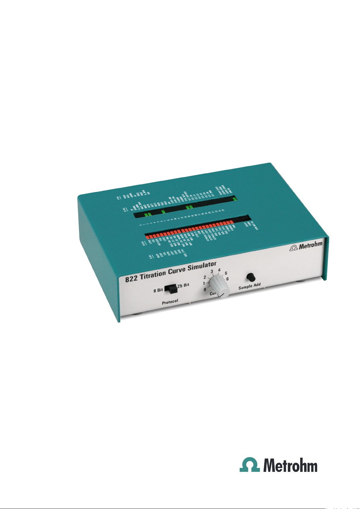
1.2 Parts and controls
Fig. 1: Front view of the Curve Simulator
1 Communication protocol
for adjusting communication type;
depends on the external dosing device
2 Curve selector
for adjusting the desired titration curve
3 Sample addition key for KF titra-
tions
simulates the sample addition after
conditioning
822 Titration Curve Simulator, Instructions for Use 1
Page 10
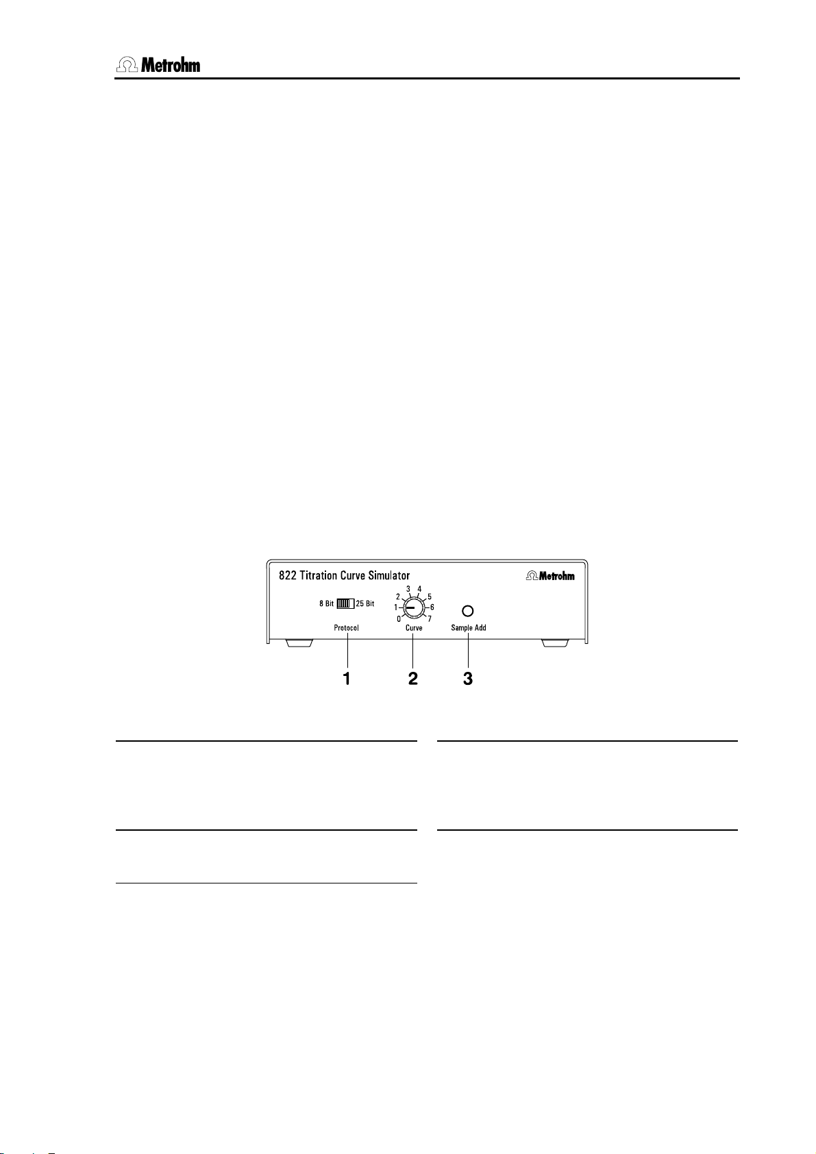
1.3 Functional principle
Fig. 2: Rear view of the Curve Simulator
4 Connector cable
connection to the titrator (MSB, Dosing
or Remote)
5 Serial number digit 1 and 2 identify
the device series, digit 3 to 5 the device
number
1.3 Functional principle
The 822 Titration Curve Simulator uses the dosing pulses of the titrator
to output, as the volume increases, an analog signal corresponding to
the titration curve selected. These values are evaluated again by the titrator and the equivalence points found are displayed. The data sets of
the titration curves are stored digitally in the Curve Simulator. This allows to achieve an excellent reproducibility of the equivalence points.
6 Connector for dosing device
directly or with 6.2134.020 adapter
cable
7 Connector for measuring signal
cable
connection to the measuring interface
with 6.2116.020 cable (2x plug type F)
2 822 Titration Curve Simulator, Instructions for Use
Page 11

2 Connection
2 Connection
Titrators with internal dosing drive do not need an additional dosing device. Titrators without internal dosing drive (e. g. 809/836 Titrando,
726/796 Titroprocessor) need a connected dosing device
(685/805 Dosimat or 700/800 Dosino). The Curve Simulator is connected between titrator and dosing device.
A detailed list of the connecting combinations can be found in the drawings given below.
Note!
The 822 Titration Curve Simulator does not replace a dosing device!
The communication protocol 1 has to be adjusted depending on the
type of the external dosing device connected. The setting is not important for internal dosing drives.
2.1 Connection to the MSB interface
2.1.1 Connection to Titrandos with internal dosing drive
Connect the 822 Titration Curve Simulator with the connector cable
4 to the MSB 2 connection of the Titrando.
Connect the measuring input of the Titrando with the Analog Output
7 of the 822 Titration Curve Simulator using the 6.2116.020 cable.
Adjust the communication protocol 1 to 25 bit.
Signals for the internal dosing drive can only be read at MSB 2. Therefore you have to activate the checkbox Send dosing signals to
MSB 2 under System/Diagnosis/822 Curve Simulator. This
setting will only be deactivated when restarting the PC Control software
or switching off and on the Touch Control.
822 Titration Curve Simulator, Instructions for Use 3
Page 12

2.1 Connection to the MSB interface
Note!
No dosing device may be connected to the 822 Titration Curve
Simulator in this case.
2.1.2 Connection to Titrandos by using an external dosing device
Connect the 822 Titration Curve Simulator with the connector cable
4 to any of the four MSB connections of the Titrando.
Connect the dosing device to the Dosing device connection 6 of the
822 Titration Curve Simulator.
Connect the Analog Output 7 with the measuring input of the Ti-
trando using the 6.2116.020 cable.
The communication protocol 1 has to be adjusted depending on
the type of external dosing device connected. 25 bit is needed for
dosing devices type 8XX, 8 bit by using a 685 Dosimat or a
700 Dosino.
variant 1:
variant 2:
4 822 Titration Curve Simulator, Instructions for Use
Page 13

2 Connection
700 Dosino
The 700 Dosino with the 8-pin MiniDIN plug type (2.700.0020) can be
connected directly to the 822 Titration Curve Simulator. If you have a
700 Dosino with a 9-pin Sub-D plug type (2.700.0010) you need the
6.2134.020 adapter cable.
Note!
With Titrandos with internal dosing drive (e. g. 808/835 Titrando) the
822 Titration Curve Simulator can only be connected to MSB 2 – MSB
4 because MSB 1 is occupied by the internal dosing drive.
2.2 Connection to the dosing interface
2.2.1 Connection to Titrinos by using an external dosing device
Connect the 822 Titration Curve Simulator with the connector cable
4 to the dosing input Dos 1 or Dos 2 of the Titrino.
Connect the dosing device to the Dosing device connection 6 of the
822 Titration Curve Simulator.
Connect the Analog Output 7 with the measuring input of the Titrino
using the 6.2116.020 cable.
Adjust the communication protocol 1 to 8 bit.
700 Dosino
The 700 Dosino with the 8-pin MiniDIN plug type (2.700.0020) can be
connected directly to the 822 Titration Curve Simulator. If you have a
700 Dosino with a 9-pin Sub-D plug type (2.700.0010) you need the
6.2134.020 adapter cable.
The endpoint volume of certain Titrino models 736, 751 and 758 is
approx. 50 % lower than the one specified for the curves. Please ask
the Metrohm service to remedy this or use the internal dosing drive.
822 Titration Curve Simulator, Instructions for Use 5
Page 14

2.3 Connection to the remote interface
2.2.2 Connection to Titroprocessors
Connect the 822 Titration Curve Simulator to the 6.2134.010 adapter
box with the connector cable 4. Connect the adapter box with one
of the dosing interfaces Dos. A1...4 of the Titroprocessor.
Connect the dosing device to the Dosing device connection 6 of the
822 Titration Curve Simulator.
Connect the Analog Output 7 with the measuring input of the Titro-
processor with the 6.2116.020 cable.
Adjust the communication protocol 1 to 8 bit.
700 Dosino
The 700 Dosino with the 8-pin MiniDIN plug type (2.700.0020) can be
connected directly to the 822 Titration Curve Simulator. If you have a
700 Dosino with a 9-pin Sub-D plug type (2.700.0010) you need the
6.2134.020 adapter cable.
2.3 Connection to the remote interface
2.3.1 Connection to Titrinos with internal dosing drive
Connect the 822 Titration Curve Simulator with the connector cable
4 to the remote interface of the Titrino.
Connect the Analog Output 7 with the measuring input of the Titrino
with the 6.2116.020 cable.
The adjustment of the communication protocol 1 does not matter in
this case.
Switch on the activation pulse of the Titrino under parame-
ters>preselections.
Note!
The parameter activate pulse does not exist for the 701 and 787
Titrinos. The conditioning must therefore be switched off so that a KF
titration can be simulated.
6 822 Titration Curve Simulator, Instructions for Use
Page 15

2 Connection
The Titrinos 701, 702, 716, 718, 719, 720, 721, 736, 787 and 794 work
with only 6000 pulses per cylinder volume. This means that the EP volumes received have to be multiplied by 0.6.
The 751 and 758 Titrinos with program version 0020 do not provide the
required pulses on the remote interface. For this device combination
you either need an update of the Titrino program software or you have
to use the 6.2148.000 remote box.
822 Titration Curve Simulator, Instructions for Use 7
Page 16

3.1 Acid-Base titration
3 Description of the titration
curves
3.1 Acid-Base titration
If you turn the curve selector to position "0", an acid-base titration with
one endpoint is simulated. Program a corresponding method and start
the titration. The illustration below shows an example of a simulated
curve.
Endpoint at (50.00 ± 0.03) % of the cylinder volume
parameters: DET pH with standard parameters
5 mL exchange unit
Stop EP: 1
Volume after EP: 0.5 mL
3.2 Titration of citric acid
If you turn the curve selector to position "1", the titration of citric acid
with three endpoints is simulated:
8 822 Titration Curve Simulator, Instructions for Use
Page 17

3 Description of the titration curves
st
1
endpoint at (17.50 ± 0.15) % of the cylinder volume
nd
endpoint at (35.0 ± 0.1) % of the cylinder volume
2
rd
3
endpoint at (52.50 ± 0.02) % of the cylinder volume
parameters: DET pH with standard parameters
5 mL exchange unit
Stop EP: 3
Volume after EP: 0.5 mL
3.3 Conditioning and Karl Fischer titration
Turn the curve selector 2 to position "3" for simulating a Karl Fischer titration (except with 701, 787 Titrino; see following page).
Program a Karl Fischer method with conditioning and sample data request. Start the conditioning. Start the titration as soon as "Conditioning
OK" is displayed. The cylinder will be filled again. Now press the key
"Sample Add" 3 and confirm the sample weight. The curve simulator
changes internally automatically to curve "4". The illustration below
shows an example of a simulated curve.
Endpoint at (26.15 ± 0.10) % of the cylinder volume
parameters: KFT Ipol with standard parameters
5 mL exchange unit
822 Titration Curve Simulator, Instructions for Use 9
Page 18

3.3 Conditioning and Karl Fischer titration
Procedure with 701, 787 Titrino:
Turn the curve selector 2 to position "4".
Program a Karl Fischer method without conditioning but with sample
data request. Start the titration and confirm the sample weight.
Note!
The endpoint of the conditioning curve "3" is at 10 % of the piston
stroke with Curve Simulators of the series 02 and 03 but at 8.4 % for
those from series 04 (see serial number, page 2). By reconditioning
with Curve Simulators of the series 02 and 03 the status "Conditioning
OK" will never be reached because the cylinder will be filled at 10 % of
the piston stroke.
10 822 Titration Curve Simulator, Instructions for Use
Page 19

4 Appendix
4 Appendix
In this section you will find the description of the additional curves of the
822 Titration Curve Simulator (for Metrohm Service technicians only) as
well as the most important technical data, a list with standard accessories and the warranty and conformity declarations.
4.1 Description of the curves
4.1.1 Recorder control
A connected recorder can be checked with curve "2". The full voltage
range is passed through twice. The range is –2.5 V to +2.5 V for devices of the series 02 and 03 (see serial number, page 2) and –2 V to
+2 V for devices from series 04.
4.1.2 Diagonal
With curve "5" the whole voltage range is run through in the form of a
diagonal. The range is –2.5 V to +2.5 V for devices of the series 02 and
03 (see serial number, page 2) and –2 V to +2 V for devices from series
04.
recorder control
2.0
1.5
1.0
0.5
0.0
-0.5
0 102030405060708090100
voltage [V]
-1.0
-1.5
-2.0
piston stroke [%]
Excel diagram from original data
822 Titration Curve Simulator, Instructions for Use 11
Page 20

4.1 Description of the curves
parameters: DET U with standard parameters
5 mL exchange unit
stop volume: 5.0 mL
4.1.3 D/A – converter test
Curve "6" checks the D/A converter in the entire voltage range from
-2.5 V to +2.5 V. The 822 Titration Curve Simulator produces the following curve:
parameters: DET U with standard parameters
5 mL exchange unit
stop volume: 5.0 mL
The A/D converter input of the titrators ranges only from –2 V to +2 V.
The area below and above is cut off.
12 822 Titration Curve Simulator, Instructions for Use
Page 21

4 Appendix
4.1.4 Testing department – test
A ramp in the voltage range of –2 V to +2 V is run through with curve
"7".
2.0
1.5
1.0
0.5
0.0
-0.5
0 5000 10000 15000 20000 25000 30000
voltage [V]
-1.0
-1.5
-2.0
Excel diagram from original data
test curve
pulse number
4.2 Meaning of the LEDs
The green LEDs represent the commands (more exactly: the single bits)
from the control device for the dosing device. The red LEDs represent
the reply i.e. the single bits from the dosing device to the control device.
Labeling on the device:
Red LEDs
serial out (SER_OUT)
serial 8-bit serial 25-bit bit-No. serial 25-bit serial 8-bit
e. g.:
685 Dosimat
700 Dosino
Reply from the dosing device 0 ... 24 Commands for the dosing device
Status information from 822 --- Status information from 822
4.2.1 Serial 8-bit
With the 8-bit transmission the single bits 0...7 have the following meanings:
e. g.:
805 Dosimat,
800 Dosino
Green LEDs
serial in (SER_IN)
e. g.:
805 Dosimat,
800 Dosino
e. g.:
685 Dosimat,
700 Dosino
Reply from the dosing device:
SER_OUT - bit 0:
BUSY
Status message for active cock
switching
SER_OUT - bit 1:
STOP
Status message if difference counter
= zero
SER_OUT - bit 2:
ESU
End switch down: cylinder at minimal
stroke
SER_OUT - bit 3:
822 Titration Curve Simulator, Instructions for Use 13
EXP0
Bit 0 for coding the cylinder volume
Page 22

4.2 Meaning of the LEDs
SER_OUT - bit 4:
SER_OUT - bit 5:
SER_OUT - bit 6:
SER_OUT - bit 7:
Commands for dosing device:
SER_IN - bit 0:
SER_IN - bit 1:
SER_IN - bit 2:
SER_IN - bit 3:
SER_IN - bit 4:
SER_IN - bit 5:
SER_IN - bit 6:
SER_IN - bit 7:
4.2.2 Serial 25 bit
EXP1
EXP2
LOCK
DOS_TYP1
POS0
POS1
DOWN
UP
NRES
POS2
R_NRW
DIR
Bit 1 for coding the cylinder volume
Bit 2 for coding the cylinder volume
Exchange unit present
Bit 1 definition of the chip function
(formerly "GTYP")
Bit 0 for the default of the desired
cock position
Bit 1 for the default of the desired
cock position
Dosing impulses for spindle motor
Filling impulses for spindle motor
Reset for the Dosimat controller
(L active)
Bit 2 for the default of the desired
cock position
Use data or set STROBE impulse
Definition of the direction of rotation
of the cock motor
With the 25 bit transmission the single bits 0...24 have the following
meanings:
Reply from the dosing device:
SER_OUT - bit 0:
STOP
Status message if difference
counter = zero
SER_OUT - bit 1:
ESU
End switch down: cylinder at
minimal stroke
SER_OUT - bit 2:
HOTLOCK
Bit for prompting the "Hot Plug
& Play" of the exchange unit
SER_OUT - bit 3:
ESO
End switch up: cylinder at
maximum stroke
SER_OUT - bit 4:
SER_OUT - bit 5:
LOCK
MOT_D0/IN0
Exchange unit present
Bit 0 D/A converter or digital
input IN0
SER_OUT - bit 6:
MOT_D1/IN1
Bit 1 D/A converter or digital
input IN1
SER_OUT - bit 7:
MOT_D2/IN2
Bit 2 D/A converter or digital
input IN2
SER_OUT - bit 8:
MOT_D3/NHWR
Bit 3 D/A converter or status
message of the reset signal
SER_OUT - bit 9:
MOT_D4/NPOR
Bit 4 D/A converter or of the
power-on-reset
SER_OUT - bit 10:
MOT_SN/OVERL
Algebraic sign of D/A converter
or motor overload
14 822 Titration Curve Simulator, Instructions for Use
Page 23

4 Appendix
SER_OUT - bit 11:
SER_OUT - bit 12:
SER_OUT - bit 13:
SER_OUT - bit 14:
SER_OUT - bit 15:
SER_OUT - bit 16:
SER_OUT - bit 17:
SER_OUT - bit 18:
SER_OUT - bit 19:
SER_OUT - bit 20:
SER_OUT - bit 21:
SER_OUT - bit 22:
SER_OUT - bit 23:
SER_OUT - bit 24:
MOT_INFO
MOT_INFO = L:
MOT_INFO = H:
BUSY
STOP_O
ESM
ISTPOS0/EXP0
ISTPOS1/EXP1
ISTPOS2/EXP2
DOS_TYP0
DOS_TYP1
DOS_TYP2
DOS_TYP3
P10000
P20000
PWR
Definition of the signals
SER_OUT bit 5 ... 10, 15 ... 17
Information about current
speed of the spindle motor
(MOT_D0…SN) and cock
position (ISTPOS0…2)
Information of the digital inputs
IN0…2, NHWR, NPOR, OVERL,
EXP0…2
Status message for active cock
switching
Driver stage spindle or cock
motor inactive
End switch middle
Bit 0 for cock position or coding
the cylinder volume
Bit 1 for cock position or coding
the cylinder volume
Bit 2 for cock position or coding
the cylinder volume
Bit 0 definition of the chip
function
Bit 1 definition of the chip
function (formerly "GTYP")
Bit 2 definition of the chip
function
Bit 3 definition of the chip
function
Bit 0 for stating the number of
pulses for the total volume
Bit 1 for stating the number of
pulses for the total volume
Enables "Hot Plug & Play" of
the device and recognize
temporally unusual supply and
control data
Commands for dosing device:
SER_IN - bit 0:
UP
Filling impulses for spindle
motor
SER_IN - bit 1:
DOWN
Dosing impulses for spindle
motor
SER_IN - bit 2:
R_NRW
Use data or set STROBE
impulse
822 Titration Curve Simulator, Instructions for Use 15
Page 24

4.2 Meaning of the LEDs
SER_IN - bit 3:
SER_IN - bit 4:
SER_IN - bit 5:
SER_IN - bit 6:
SER_IN - bit 7:
SER_IN - bit 8:
SER_IN - bit 9:
SER_IN - bit 10:
SER_IN - bit 11:
SER_IN - bit 12:
SER_IN - bit 13:
SER_IN - bit 14:
SER_IN - bit 15:
SER_IN - bit 16:
SER_IN - bit 17:
SER_IN - bit 18:
SER_IN - bit 19:
SER_IN - bit 20:
SER_IN - bit 21:
SER_IN - bit 22:
SER_IN - bit 23:
SER_IN - bit 24:
MOT_INFO
MOT_INFO = L:
MOT_INFO = H:
NRES
OUT0
OUT1
OUT2
POS0
POS1
POS2
DIR
STOP_HM
STOP_SM
P10000
P20000
TITR_NLIQ
SET_HOTLOCK
EXT_D0
EXT_D1
EXT_D2
EXT_D3
EXT_D4
EXT_SN
SET_PWR
Definition of the digital signals
SER_OUT bit 5 ... 10, 15 ... 17
Information about current
speed of the spindle motor
(MOT_D0…SN) and cock
position (ISTPOS0…2)
Information of the digital inputs
IN0…2, NHWR, NPOR, OVERL,
EXP0…2
Reset for dosimat controller
(L active)
Bit 0 digital output
Bit 1 digital output
Bit 2 digital output
Bit 0 for the default of the
desired cock position
Bit 1 for the default of the
desired cock position
Bit 2 for the default of the
desired cock position
Definition of the direction of
rotation of the cock motor
Signal to switch off the driver
stage of the cock motor
Signal to switch off the driver
stage of the spindle motor
Bit 0 for stating the number of
pulses for the total volume
Bit 1 for stating the number of
pulses for the total volume
Definition of the mechanism of
the motor controller
Enables "Hot Plug & Play" of
the exchange unit
Bit 0 for the theoretical speed
of the spindle motor
Bit 1 for the theoretical speed
of the spindle motor
Bit 2 for the theoretical speed
of the spindle motor
Bit 3 for the theoretical speed
of the spindle motor
Bit 4 for the theoretical speed
of the spindle motor
SIGN for the specification of the
direction of rotation of the
spindle motor
Enables "Hot Plug & Play" of
the device and recognize
temporally unusual supply and
control data
16 822 Titration Curve Simulator, Instructions for Use
Page 25

4 Appendix
Meaning of the red status LEDs:
DAISY:
With the serial protocol several devices can be at the same bus one after the other in a so-called daisy-chain configuration but only one of
them is active. The so-called daisy signal is produced with SHIFT,
STROBE and the momentary condition of SER_IN to switch to the next
device.
COND.:
When "Conditioning OK" is displayed on the titrator, no further pulses
are coming from the titrator and the voltage at the "Analog Output" 7
remains at the same level. The air humidity is not simulated. After pressing "Sample Add" 3 the LED "COND" is switched on to show that the
Karl Fischer curve is running now.
SIMI NOT OK:
When switching on the titrator a self test of the internal reference and
supply voltages is carried out in the 822 Titration Curve Simulator. The
self test is carried out also at a reset of the Curve Simulator caused by
rotating the cock at the dosing device or a reset command on a serial
transmission. After the self test the display changes to "SIMI OK".
Meaning of the green status LEDs:
CURVE STATE:
If the 822 Titration Curve Simulator recognizes pulses for ejecting at the
dosing device, the LED "CURVE STATE" starts blinking i.e. it stays dark
for 500 pulses and bright for the next 500 pulses and so on.
CURVE 6000:
not in use
CURVE 20000:
If dosing is done with a 805 Dosimat or with the internal dosing drive of
the Titrando and a stroke with 20'000 pulses is ejected, this LED is
blinking synchronously with the LED "CURVE STATE".
SIMI OK:
see SIMI NOT OK
822 Titration Curve Simulator, Instructions for Use 17
Page 26

4.3 Technical data
4.3 Technical data
4.3.1 Control
parallel
serial
4.3.2 Curves
Curve memory
Number of curves
Flash
Curve types
Acid-Base
Citric acid
Recorder control
Conditioning
Karl Fischer
Diagonal
D/A converter test
Testing department test
Remote
8 bit / 25 bit
8
4 Mbit
+240 mV ... –300 mV
Endpoint at (50.00 ± 0.03) % of the cylinder volume
+250 mV ... –300 mV
st
endpoint at (17.50 ± 0.15) % of the cylinder volume
1
nd
endpoint at (35.0 ± 0.1) % of the cylinder volume
2
rd
endpoint at (52.50 ± 0.02) % of the cylinder volume
3
steps of 200 mV per 2.5 % of the cylinder volume over
the whole voltage range
series 02, 03: –2.5 V ... +2.5 V ... –2.5 V
from series 04: –2 V ... +2 V ... –2 V
series 02, 03: end at 10 % of the cylinder volume
from series 04: end at 8.4 % of the cylinder volume
Endpoint at (26.15 ± 0.10) % of the cylinder volume
series 02, 03: –2.5 V ... +2.5 V
from series 04: –2 V ... +2 V
–2.5 V ... +2.5 V
–2.0 V ... +2.0 V
Reproducibility of the endpoints (volume)
Acid-Base
Citric Acid
st
endpoint
1
nd
endpoint
2
rd
endpoint
3
Karl Fischer
99.9 %
97.5 %
99.5 %
99.95 %
99.5 %
4.3.3 Analog output
Range
18 822 Titration Curve Simulator, Instructions for Use
–2.5 V ... +2.5 V
Page 27

4 Appendix
4.3.4 Resolution
D/A converter
LSB
Curve
16 bit
76.3 µV
20'000 Word
4.3.5 Supply
Voltage
Power consumption
+5 V / +12 V
0.1 W
4.3.6 Safety specifications
Construction and testing According to EN/IEC 61010-1, UL3101-1
4.3.7 Electromagnetic compatibility (EMC)
Emission Standards complied with:
- EN/IEC 61326
- EN 55022 / CISPR 22
Immunity Standards complied with:
- EN/IEC 61326
- EN/IEC 61000-4-2
- EN/IEC 61000-4-3
- EN/IEC 61000-4-4
- EN/IEC 61000-4-5
- EN/IEC 61000-4-6
4.3.8 Ambient temperature
Nominal working range
Storage
Transport
+5 °C...+45 °C (at max. 85% rel. humidity)
–40 °C...+70 °C
–40 °C...+70 °C
4.3.9 Reference conditions
Ambient temperature
Rel. humidity
Warmed-up condition
+25 °C (±3 °C)
≤60%
Instrument in operation for at least 30 min
4.3.10 Dimensions
Housing material Sheet steel 1 mm
Width
Height
Depth
Weight 704 g
150 mm
41 mm
118 mm
822 Titration Curve Simulator, Instructions for Use 19
Page 28

4.4 Standard equipment
4.4 Standard equipment
4.4.1 822 Titration Curve Simulator
No. Order No. Description
1 1.822.0010 822 Titration Curve Simulator
1 6.2116.020 Cable for connection to the meas-
uring input; 2 plugs type F (1 m)
1 6.2134.010 Adapter box DB9 plug / Mini-DIN8
socket
1 6.2134.020 Adapter cable DB9 socket / Mini-
DIN8 plug for connecting a
685 Dosimat and 700 Dosino with
9-pin Sub-D plug (1.700.0010)
1 6.2151.040 Connecting cable Curve simulator –
Titrino (Remote interface)
1 8.822.1011 Instructions for Use for 822 Titration Curve Simulator
20 822 Titration Curve Simulator, Instructions for Use
Page 29

4 Appendix
4.5 Warranty and conformity
4.5.1 Warranty
The warranty on our products is limited to defects that are traceable to
material, construction or manufacturing fault which occur within 12
months from the day of delivery. In this case the defects will be rectified
in our workshops free of charge. Transport costs are to be paid by the
customer.
For day and night operation the warranty is limited to 6 months.
Glass breakage in the case of electrodes or other parts is not covered
by the warranty. Checks which are not a result of material or manufacturing faults are also charged during the warranty period. For parts from
outside manufacturers, insofar as these constitute an appreciable part
of our instrument, the warranty stipulations of the manufacturer in question apply.
With the regard to the guarantee of accuracy the technical specifications in the instruction manual are authoritative.
Concerning defects in materials, construction or design as well as the
absence of guaranteed features the purchaser has no rights or claims
except those mentioned above.
If damage of the packaging is evident on receipt of a consignment or if
the goods show signs of transport damage after unpacking, the carrier
must be informed immediately and a written damage report demanded.
Lack of an official damage report releases Metrohm from any liability to
pay compensation.
If any instruments and parts have to be returned then the original packaging should be used if at all possible. This applies above all to instruments, electrodes, buret cylinders and PTFE pistons. Before embedment in wood shavings or similar material, the parts must be packed in
a dustproof package (for instruments the use of a plastic bag is essential). If open assemblies are included that are sensitive to electromagnetic interferences [fields] (e. g. data interfaces, etc.) then these must
be returned in the associated original protective packaging (e. g. conductive protective bag). (Exception: assemblies with a built-in voltage
source belong in non-conductive protective packaging.)
For damage which arises as a result of non-compliance with these instructions, no warranty responsibility whatsoever will be accepted by
Metrohm.
822 Titration Curve Simulator, Instructions for Use 21
Page 30

4.5 Warranty and conformity
4.5.2 Declaration of Conformity
This is to certify the conformity to the standard specifications for electrical appliances and accessories,
as well as to the standard specifications for security and to system validation issued by the manufacturing company.
Name of commodity
822 Titration Curve Simulator
Description GLP test device for system check. Different types of curves can be simulated for
verification of dosing output, electrode input and titration software.
This instrument has been built and has undergone final type testing according to the standards:
Electromagnetic compatibility: Emission
EN/IEC 61326, EN 55022 / CISPR 22
Electromagnetic compatibility: Immunity
EN/IEC 61326, EN/IEC 61000-4-2, EN/IEC 61000-4-3, EN/IEC 61000-4-4, EN/IEC 61000-4-5,
EN/IEC 61000-4-6
CH-9101 Herisau/Switzerland
E-Mail info@metrohm.com
www.metrohm.com
Safety specifications
EN/IEC 61010-1, UL3101-1
The instrument meets the requirements of the CE mark as contained in the EU directives 89/336/EEC and 73/23/EEC and fulfils the following specifications:
EN 61326 Electrical equipment for measurement, control and laboratory use – EMC requirements
EN 61010-1 Safety requirements for electrical equipment for measurement, control and laboratory
use
Metrohm Ltd. is holder of the SQS-certificate of the quality system ISO 9001 for quality assurance in
design/development, production, installation and servicing.
The system software, stored in Read Only Memories (ROMs) has been validated in connection with
standard operating procedures in respect to functionality and performance.
The technical specifications are documented in the instruction manual.
Herisau, February 28, 2002
Dr. J. Frank Ch. Buchmann
Vice President Vice President
Head of R&D Head of Production
Responsible for Quality Assurance
22 822 Titration Curve Simulator, Instructions for Use
Page 31

4 Appendix
4.5.3 Quality Management Principles
Metrohm Ltd., CH-9101 Herisau, Switzerland
CH-9101 Herisau/Switzerland
E-Mail info@metrohm.com
Internet www.metrohm.com
Metrohm Ltd. holds the ISO 9001 Certificate, registration number 10872-02, issued by
SQS (Swiss Association for Quality and Management Systems). Internal and external audits are carried out periodically to assure that the standards defined by Metrohm’s QM
Manual are maintained.
The steps involved in the design, manufacture and servicing of instruments are fully
documented and the resulting reports are archived for ten years. The development of
software for PCs and instruments is also duly documented and the documents and
source codes are archived. Both remain the possession of Metrohm. A non-disclosure
agreement may be asked to be provided by those requiring access to them.
The implementation of the ISO 9001
quality system is described in Metrohm’s
QM Manual, which comprises detailed
instructions on the following fields of
activity:
Instrument development
The organization of the instrument
design, its planning and the intermediate
controls are fully documented and
traceable. Laboratory testing accompanies all phases of instrument development.
Software development
Software development occurs in terms of
the software life cycle. Tests are
performed to detect programming errors
and to assess the program’s functionality in a laboratory environment.
Components
All components used in the Metrohm
instruments have to satisfy the quality
standards that are defined and implemented for our products. Suppliers of
components are audited by Metrohm as
the need arises.
Manufacture
The measures put into practice in the
production of our instruments guarantee
a constant quality standard. Production
planning and manufacturing procedures,
maintenance of production means and
testing of components, intermediate and
finished products are prescribed.
Customer support and service
Customer support involves all phases of
instrument acquisition and use by the
customer, i.e. consulting to define the
adequate equipment for the analytical
problem at hand, delivery of the equipment, user manuals, training, after-sales
service and processing of customer
complaints. The Metrohm service organization is equipped to support customers in implementing standards such
as GLP, GMP, ISO 900X, in performing
Operational Qualification and Performance Verification of the system components or in carrying out the System
Validation for the quantitative determination of a substance in a given matrix.
822 Titration Curve Simulator, Instructions for Use 23
Page 32

5 Index
5 Index
A
Ambient temperature......... 19
Analog output ....................18
Appendix............................ 11
C
Communication protocol..... 1
Connection
Device.......................... 3
Dosing device .............2
Dosing interface ..........5
Measuring signal cable
.....................................2
MSB interface.............. 3
Remote interface......... 6
to Titrandos .............3, 4
to Titrinos.................5, 6
to Titroprocessors ....... 6
Connector cable .................. 2
Control ...............................18
Curve
Curve memory........... 18
Curve types ............... 18
Curve description ..........8, 11
Curve selector...................... 1
Curves................................ 18
D
D/A - converter test............ 12
Description
Curves ...................8, 11
Diagonal.............................11
Dimensions........................19
E
Electromagnetic compatibility
...........................................19
EMC ...................................19
F
Front view.............................1
Functional principle .............2
I
Instrument description.........1
Introduction..........................1
P
Parts and controls ...............1
R
Rear view .............................2
Recorder control ................11
Reference conditions.........19
Reproducibility
Endpoints ..................18
Resolution ..........................19
S
Safety specifications..........19
Sample addition key ............1
Serial number.......................2
Simulation
Acid-Base titration .......8
Karl Fischer titration.....9
Titration of citric acid ...8
Standard equipment..........20
Status LED
Meaning.....................13
Serial 25 bit ................14
Serial 8 bit ..................13
Supply ................................19
T
Testing department test.....13
Transport damage .............21
W
Warranty.............................21
24 822 Titration Curve Simulator, Instructions for Use
 Loading...