

Page 1
818 IC Pump
Manual
8.818.1023
Page 2

Page 3

Metrohm AG
CH-9101 Herisau
Switzerland
Phone +41 71 353 85 85
Fax +41 71 353 89 01
info@metrohm.com
www.metrohm.com
818 IC Pump
5.818.0110 Program
Manual
8.818.1023 11.2005 chs
Page 4

Teachware
Metrohm AG
CH-9101 Herisau
teachware@metrohm.com
This documentation is protected by copyright. All rights reserved.
Although all the information given in this documentation has been
checked with great care, errors cannot be entirely excluded. Should you
notice any mistakes please send us your comments using the address
given above.
Documentation in additional languages can be found on
http://products.metrohm.com under Literature/Technical documenta-
tion.
Page 5

Table of contents
Table of contents
1 Introduction.................................................... 1
1.1 Instrument description ............................................................. 1
1.2 Parts and controls .................................................................... 2
1.3 Information about the Instructions for Use ............................. 4
1.3.1 Organization ..................................................................................4
1.3.2 Notation and pictograms ..............................................................5
1.4 Safety notes ..............................................................................6
1.4.1 Electrical safety..............................................................................6
1.4.2 General safety rules.......................................................................6
2 Installation ..................................................... 7
2.1 Setting up the instrument ......................................................... 7
2.1.1 Packaging...................................................................................... 7
2.1.2 Check.............................................................................................7
2.1.3 Location ......................................................................................... 7
2.1.4 Arrangement of the instruments....................................................7
2.2 Mounting the pump head ......................................................... 8
2.3 Attaching the accessories........................................................ 9
2.3.1 Capillaries ...................................................................................... 9
2.3.2 Pulsation dampener ......................................................................9
2.3.3 Filter unit PEEK............................................................................10
2.4 Connecting the tubing ............................................................ 11
2.4.1 Connection to injection valve ......................................................11
2.4.2 Connection to eluent container ...................................................12
2.5 Electrical connection .............................................................. 13
2.5.1 Connection to 830 IC Interface ...................................................13
2.5.2 Connection to PC ........................................................................14
2.6 Mains connection.................................................................... 15
2.6.1 Setting the mains voltage............................................................15
2.6.2 Fuses ...........................................................................................16
2.6.3 Mains cable .................................................................................16
2.6.4 On/off switching of the instrument ..............................................16
2.7 Software installation ............................................................... 17
2.8 Deaerating the pump .............................................................. 17
3 Operation...................................................... 18
3.1 Switch instrument on/off ........................................................ 18
3.2 818 IC Pump icon.................................................................... 18
3.3 Settings in the "818 IC Pump" window................................... 18
4 Notes – Maintenance – Faults...................... 23
4.1 Practical notes ........................................................................ 23
4.1.1 Protection against foreign particles ............................................23
4.1.2 Pulsation dampener ....................................................................23
4.1.3 Eluents......................................................................................... 23
4.2 Maintenance and servicing ....................................................24
4.2.1 General information.....................................................................24
4.2.2 Maintenance work at the pump head .........................................25
4.3 Faults and malfunctions ......................................................... 30
818 IC Pump / 8.818.1023 Instructions for Use
I
Page 6

Table of contents
5 Interfaces ..................................................... 31
5.1 RS 232 interface...................................................................... 31
5.1.1 Data transmission protocol......................................................... 31
5.1.2 Pin assignment............................................................................ 32
5.2 Control interface ..................................................................... 33
5.2.1 Functions..................................................................................... 33
5.2.2 Control inputs and outputs .........................................................33
6 Appendix ....................................................... 36
6.1 Technical specifications......................................................... 36
6.2 Scope of delivery .................................................................... 39
6.3 Optional accessories .............................................................. 41
6.4 Validation / GLP ...................................................................... 44
6.5 Warranty and Conformity .......................................................45
6.5.1 Warranty ......................................................................................45
6.5.2 Declaration of Conformity ...........................................................46
6.5.3 Quality Management Principles .................................................. 47
6.6 Index ........................................................................................ 48
List of figures
Fig. 1: Front of 818 IC Pump....................................................................... 2
Fig. 2: Rear of 818 IC Pump ....................................................................... 3
Fig. 3: Connect capillaries .......................................................................... 9
Fig. 4: Filter unit PEEK (6.2821.120) ......................................................... 10
Fig. 5: Connection to injection valve......................................................... 11
Fig. 6: Connection of 818 IC Pump to 830 IC Interface ............................ 13
Fig. 7: Connection of 818 IC Pump to PC ................................................ 14
Fig. 8: Components of the pump head .................................................... 26
Fig. 9: Replacement of the piston seal 34................................................ 26
Fig. 10: Components of inlet valve 35 and outlet valve 36......................... 29
818 IC Pump / 8.818.1023 Instructions for Use
II
Page 7
1.1 Instrument description
1 Introduction
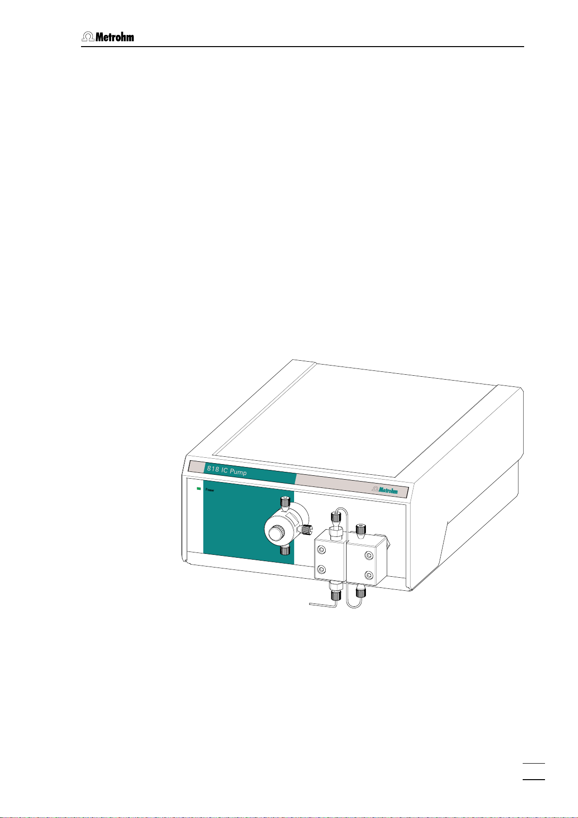
1.1 Instrument description
The 818 IC Pump is a serial dual piston pump especially developed for
ion chromatography and optimized for use with Metrohm ion
chromatographic instruments (e.g. 819 IC Detector and 820 IC
Separation Center). The 818 IC Pump operates with minimal residual
pulsation and has an excellent flow constancy. All wet parts of the
pump are metal free.
The 818 IC Pump is completely remote controlled by the Metohm
software «IC Net» (version 2.3 or higher). All functions are fast and
easily accessible via software and can be clearly arranged at the
monitor. To assure optimum operational reliability, both lower and
upper pressure limit values can be set. If such a limit is reached, the
pump switches itself off automatically. An additional purge valve allows
rapid removal of air from the pump system.
818 IC Pump / 8.818.1023 Instructions for Use
1
Page 8
1 Introduction
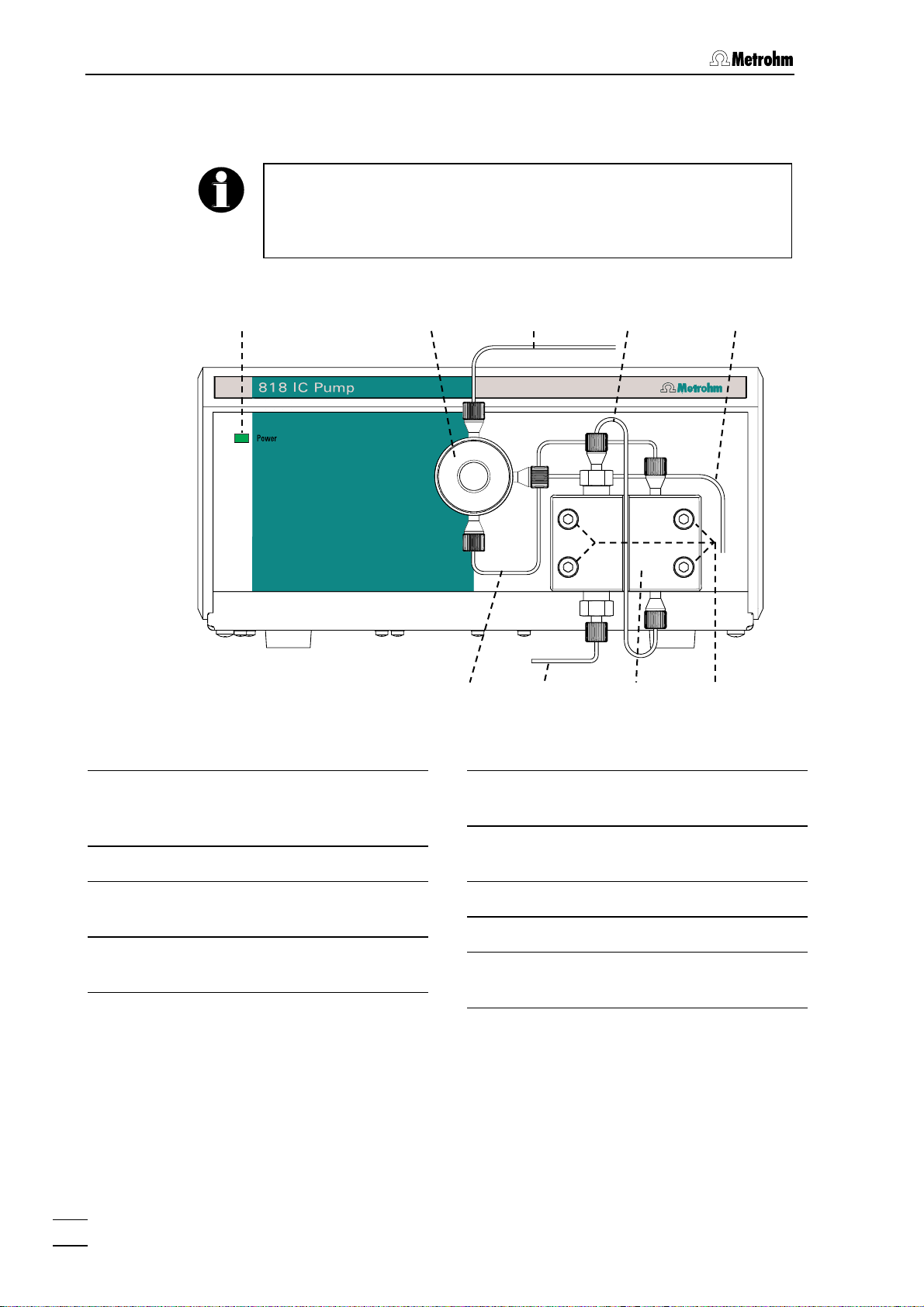
1.2 Parts and controls
In this section you will find the numbers and designations of the parts
and controls of the 818 IC Pump. The numbering applies throughout
the instructions for use, i.e. bold numbers in the text (e.g.
the parts and controls illustrated here.
1 2 3 4 5
11
) refer to
Fig. 1: Front of 818 IC Pump
Mains pilot lamp
1
Lights up when instrument is switched
on
Purge valve
2
Connection capillary
3
to injection valve of IC system.
Connection capillary
4
in pump head (intergal)
6 7 8 9
Outlet capillary
5
of Purge-Ventil.
Connection capillary
6
between pump head and purge valve.
Aspirating capillary
7
Pump head 6.2824.100
8
Fastening screws
9
for pump head
2
818 IC Pump / 8.818.1023 Instructions for Use
Page 9
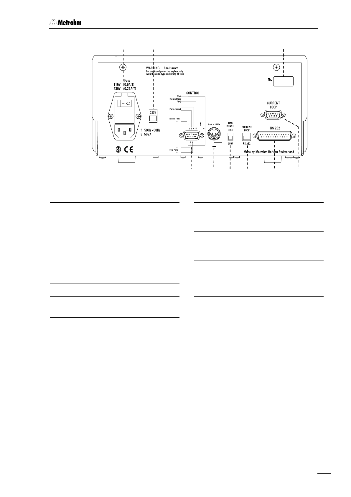
1.2 Parts and controls
Fig. 2: Rear of 818 IC Pump
Fuse cover
10
Changing the fuses, see section 2.6.2.
Mains switch
For switching instrument on/off:
I = ON 0 = OFF
Mains connector
For mains connection see section 2.6.
1110
12
13 14 15 16 17 18
Recorder output
14
For recording the pressure,
1 mV = 1 MPa
Switch "Time Constant"
15
Time constant for the recorder output:
HIGH ≈ 1 s; LOW ≈ 20 ms
Mains voltage selector
11
Voltage selection see section 2.6.1.
Serial number
12
Control interface
13
details see section 5.2.
Switch for external control
16
Selector to choose the interface for
remot control of the pump
RS 232 / Current Loop
RS 232 interface
17
Current Loop interface
18
(Details on request)
818 IC Pump / 8.818.1023 Instructions for Use
3
Page 10

1 Introduction
1.3 Information about the Instructions for Use
Please read through these Instructions for Use carefully before
operating the 818 IC Pump. The Instructions for Use contain
information and warnings to which the user must pay attention in order
to assure safe operation of the instrument.
1.3.1 Organization
These 8.818.1023 Instructions for Use for the 818 IC Pump provide a
comprehensive overview of the installation, startup procedure,
operation, fault rectification and technical specifications of this
instrument. The Instructions for Use are organized as follows:
Section 1 Introduction
Description of the instrument, parts and controls,
safety notes
Section 2 Installation
Mounting the pump head, electrical connections,
tubing connections, mains connection
Section 3 Operation
Operation via «IC Net»
Section 4 Notes – Maintenance – Faults
Practical notes, maintenance, fault rectification
Section 5 Interfaces
Description of the interfaces
Section 6 Appendix
Technical data, standard equipment, options,
validation, warranty, declaration of conformity, index
To find the information you require about the instrument please use
either the Table of contents or the Index at the back.
4
818 IC Pump / 8.818.1023 Instructions for Use
Page 11
1.3 Information about the Instructions for Use
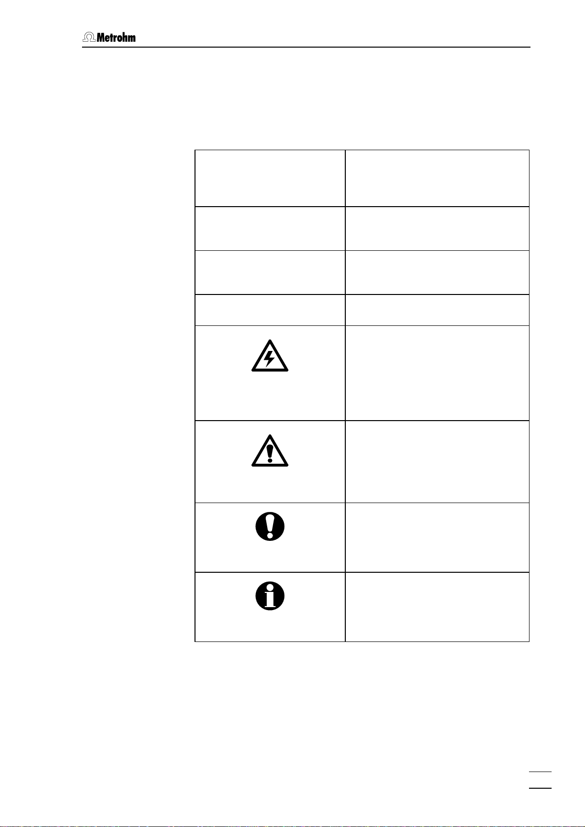
1.3.2 Notation and pictograms
The following notations and pictograms (symbols) are used in these
Instructions for Use:
Range Menu item, parameter or entry
value
in «IC Net» program
SYSTEM STATE Program window
in «IC Net» program
<OK> Button
in «IC Net» program
10 Part or control of 818
Danger/Warning
This symbol indicates a possible
risk of death or injury to the user
and possible damage to the
instrument or its components by
electricity.
Danger/Warning
This symbol indicates a possible
risk of death or injury to the user
and possible damage to the
instrument or its components.
Attention
This symbol indicates important
information that you should read
before continuing.
Information
This symbol indicates additional
information and tips which may be
of particular use to you.
818 IC Pump / 8.818.1023 Instructions for Use
5
Page 12
1 Introduction
1.4 Safety notes
1.4.1 Electrical safety
While electrical safety in the handling of the 818 IC Pump is assured in
the context of the specifications IEC 1010-1 (protection class 1, degree
of protection IP40), the following points should be noted:
• Mains connection
Set the mains voltage and check the mains fuse and mains
connection in accordance with the instructions in section 2.6.
• Opening the instrument
Inside the instrument there are no parts which must be set or adjusted
by the user.
If the 818 IC Pump is connected to the power supply, the instrument
must not be opened nor must parts be removed from it, otherwise
there is a danger of coming into contact with components which are
live. Hence, always disconnect the instrument from all voltage sources
before you open it and ensure that the mains cable is
disconnected from mains connection 10 !
• Protection against static charges
Electronic components are sensitive to static charging and can be
destroyed by discharges. Before you touch any of the components
inside the 818 IC Pump, you should earth yourself and any tools you
are using by touching an earthed object (e.g. housing of the
instrument or a radiator) to eliminate any static charges which exist.
1.4.2 General safety rules
• Handling of solvents
Check the pump tubing and all input and output leads periodically for
possible leaks. Follow the relevant instructions regarding the handling
of flammable and/or toxic solvents and their disposal.
6
818 IC Pump / 8.818.1023 Instructions for Use
Page 13
2.1 Setting up the instrument
2 Installation
2.1 Setting up the instrument
2.1.1 Packaging
The 818 IC Pump is supplied together with the separately packed
accessories in special packagings containing shock-absorbing foam
linings designed to provide excellent protection. The actual instrument
is packed in an evacuated polyethylene bag to prevent the ingress of
dust. Please store all these special packagings as only they assure
transport of the instruments free from damage.
2.1.2 Check
After receipt, immediately check whether the shipment is complete and
has arrived without damage (compare with delivery note and list of
accessories in section 6.2). In the case of transport damage, see
instructions in section 6.5.1 "Warranty".
2.1.3 Location
Position the 818 IC Pump in the laboratory at a location convenient for
operation, free from vibrations and protected against a corrosive
atmosphere and contamination by chemicals.
To avoid disturbing temperature influences on the insulated column
compartment, the pump and eluent reservoir must be protected
against direct sunlight.
2.1.4 Arrangement of the instruments
The 818 IC Pump should always be at the very bottom of a IC system.
The 818 IC Pump should always be placed at the bottom of the
instrument stack so that any leaks which may occur in the pump
tubing or connections cannot cause damage to the other instruments
by leakage liquids.
818 IC Pump / 8.818.1023 Instructions for Use
7
Page 14
2 Installation
2.2 Mounting the pump head
1 Remove the transportation lock
To ensure that the pump drive is not damaged during transport
a black plastic block is mounted in place of the pump head on
the right side of the 818 IC Pump front panel. This transport
safeguard block has to be removed after undoing the four
screws 9.
To avoid any damage to the pump head, the protective block must be
remounted if the pump has to be moved any great distance.
2 Mounting the pump head
The Pump Head 8 (6.2824.100) with integrated piston units is
unpacked and fixed in place of the transport safeguard block
with the four hexagon screws 9as shown in Fig. 2 .
To ensure that the pump head is not positioned wrongly, the holes at
the rear for the clamping bolts have different depths, i.e. 1 clamping
bolt is longer than the rest. The deepest hole must naturally
accommodate the longest bolt. If this is not the case, the pump will
not function properly.
3 Connecting capillary to pump head
The connection capillary 6 fastened to purge valve 2 is
screwed onto the pump head 8 as shown in Fig. 2.
The pressure range of the 818 IC Pump with the 6.28.24.100 PEEK
…
pump head isf 0
30.0 MPa (0…300 bar)..
8
818 IC Pump / 8.818.1023 Instructions for Use
Page 15
2.3 Attaching the accessories
2.3 Attaching the accessories
2.3.1 Capillaries
Some of the connections under high pressure between the 818 IC
Pump and the IC system must be set up by the user, see section 2.4.
For that the 6.1831.010 PEEK capillary (i.d. = 0.25 mm, o.d. =
length = 3 m) supplied in the accessories of the 818 IC Pump can be
used.
Capillaries fitted with new connectors must have a perfectly flat cut
surface. For PEEK capillaries it is best to use the 6.2621.080
Capillary tubing cutter
1
/16",
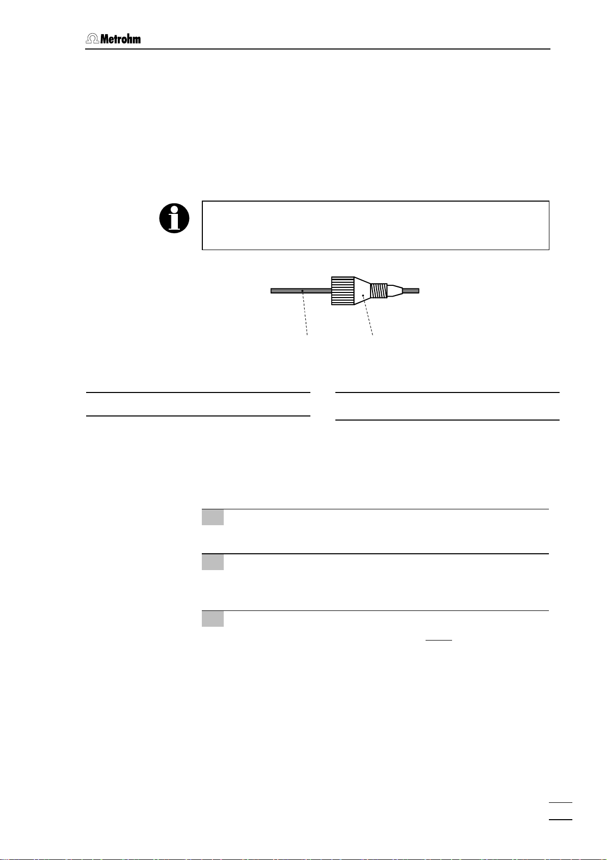
Fig. 3: Connect capillaries
PEEK capillary (6.1831.010)
19
20 19
Compression fitting (6.2744.010)
20
For the connection of 6.1831.010 PEEK capillaries or of the 6.1834.000
PTFE aspirating tubing, the supplied 6.2744.010 PEEK Compression
fittings are used. It is best to proceed as follows:
1 Mount compression fitting
Slide a compression fitting 20 (6.2744.010) over the end of the
capillary 19 to be fastened as shown in Fig. 3.
2 Insert capillary in connection
Push capillary end in the corresponding connection as far as it
will go (to avoid dead volume).
3 Tighten compression fitting
Tighten compression fitting 20 by hand (never use tools).
2.3.2 Pulsation dampener
To protect the column material against pressure drops caused by the
injector, the use of a pulsation dampener connected between the pump
and the injection valve of the 820 IC Separation Center is
recommended. The optional 6.2620.150 Pulsation dampener MF is
very well suited to this purpose (see section 6.3).
The metal-free 6.2620.150 Pulsation dampener is supplied fully
assembled and has two connections for capillaries, for which two
818 IC Pump / 8.818.1023 Instructions for Use
9
Page 16
2 Installation
6.2744.010 PEEK compression fittings can be used. The flow direction
is arbitrary. The pulsation dampener is positioned in the interior of the
820 IC Separation Center on the base below the injection valve (see
819/820 Instructions for Use).
The pulsation dampener is filled with isopropanol when new. Rinse
your IC system carefully after the first installation of a new pulsation
dampener.
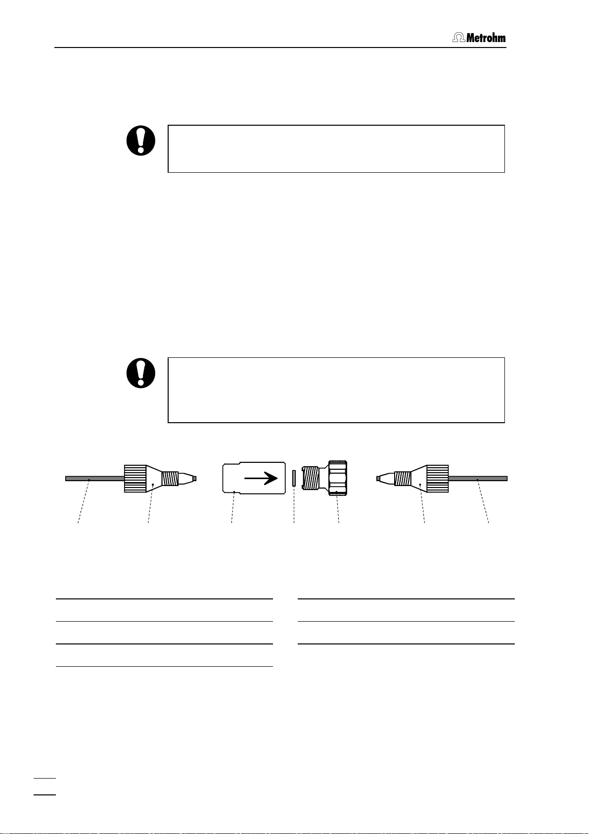
2.3.3 Filter unit PEEK
The 6.2821.120 Filter unit PEEK 24 supplied (see Fig. 4) serves to
avoid contamination of the piston seals by abrasive particles and can
be used in the pressure range 0…30 MPa (0…300 bar). The filter unit
consists of the housing 21, the filter 22 and the connector 23 to be
screwed into the housing 21. For the connection of capillaries 19, PEEK
compression fittings 20 (6.2744.010) must be used.
New filter 22 are available as an option with the ordering number
6.2821.110 (10 pieces).
For the connection of the filter unit, please note the flow direction
arrow printed on the housing.
The filter unit is filled with isopropanol when new. Rinse your IC system
carefully after the first installation of a new filter unit.
20 19 20 232221 19
Fig. 4: Filter unit PEEK (6.2821.120)
PEEK capillary (6.1831.010)
19
Compression fitting (6.2744.010)
20
Filter housing
21
Filter 6.2821.130
22
Filter connector
23
10
818 IC Pump / 8.818.1023 Instructions for Use
Page 17
2.4 Connecting the tubing
2.4 Connecting the tubing
2.4.1 Connection to injection valve
It is recommended to use 6.1831.010 PEEK capillaries, a 6.2620.150
Pulsation dampener (see section 2.3.2), and a Filter unit PEEK (see
section 2.3.3) to connect the 818 IC Pump to the injection valve of the
820 IC Separation Center. Proceed as follows:
25 243
Fig. 5: Connection to injection valve
Connection capillary
3
to 820 IC Separation Center.
PEEK capillary (6.1831.010)
818
Filter unit PEEK (6.2821.120)
24
Pulsation dampener (6.2620.150)
25
820
1 Connection to 818 IC Pump
• Cut connection capillary 3 (6.1831.010 PEEK capillary) to the
required length and equip it with compression fittings.
• Attach connection capillary 3 to the upper connection of the
purge valve (see Fig. 1).
2 Connection of filter unit PEEK
• Attach the other end of connection capillary 3 at the filter
housing 21 of the filter unit 24 (see Fig. 4).
• Connect a PEEK capillary 6.1831.010 cut to the required
length and equipped with connectors to the filter connector
23 of the filter unit 24.
3 Installation of the capillary in the IC Separation
Center
4 Connection of the pulsation dampener
5 Connection to the injection valve
818 IC Pump / 8.818.1023 Instructions for Use
• Procedure, see 819/820 Instructions for Use.
• Procedure, see section 2.3.2.
• Procedure, see section 2.3.3.
11
Page 18

2 Installation
2.4.2 Connection to eluent container
The 6.1834.000 Aspirating tubing (i.d. = 1.5 mm, o.d. = 2.5 mm,
length = 1.2 m) supplied is slid over the aspirating capillary 7. The
6.2821.090 Aspirating filter supplied is screwed onto the other end of
the tubing. The end of the tubing with the aspirating filter is then
introduced in the eluent container.
Only degassed (with N
, He or vacuum) and microfiltered (0.45 µm
2
filter) eluents may be used!
It must be ensured that the eluent used is freely miscible with any
residual solvent in the pump head (the pump head is filled with
isopropanol or methanol/water in the factory). If this is not the case,
the pump must first be rinsed with a solvent that is miscible with both
the previous and subsequent eluent (e.g. acetone).
If you use the optional available 6.5324.000 Bottle rack, the
6.1834.010 Aspirating tubing (accessory of the bottle rack, length =
2.5 m) must be installed instead of the 6.1834.000 Aspirating tubing.
The end of the tubing with the screwed-on 6.2821.090 aspirating filter
is then fixed in the eluent vessel according to the instructions on the
leaflet supplied with the bottle rack.
12
818 IC Pump / 8.818.1023 Instructions for Use
Page 19

2.5 Electrical connection
2.5 Electrical connection
Switch off both devices before connecting the 818 IC Pump to
another instrument.
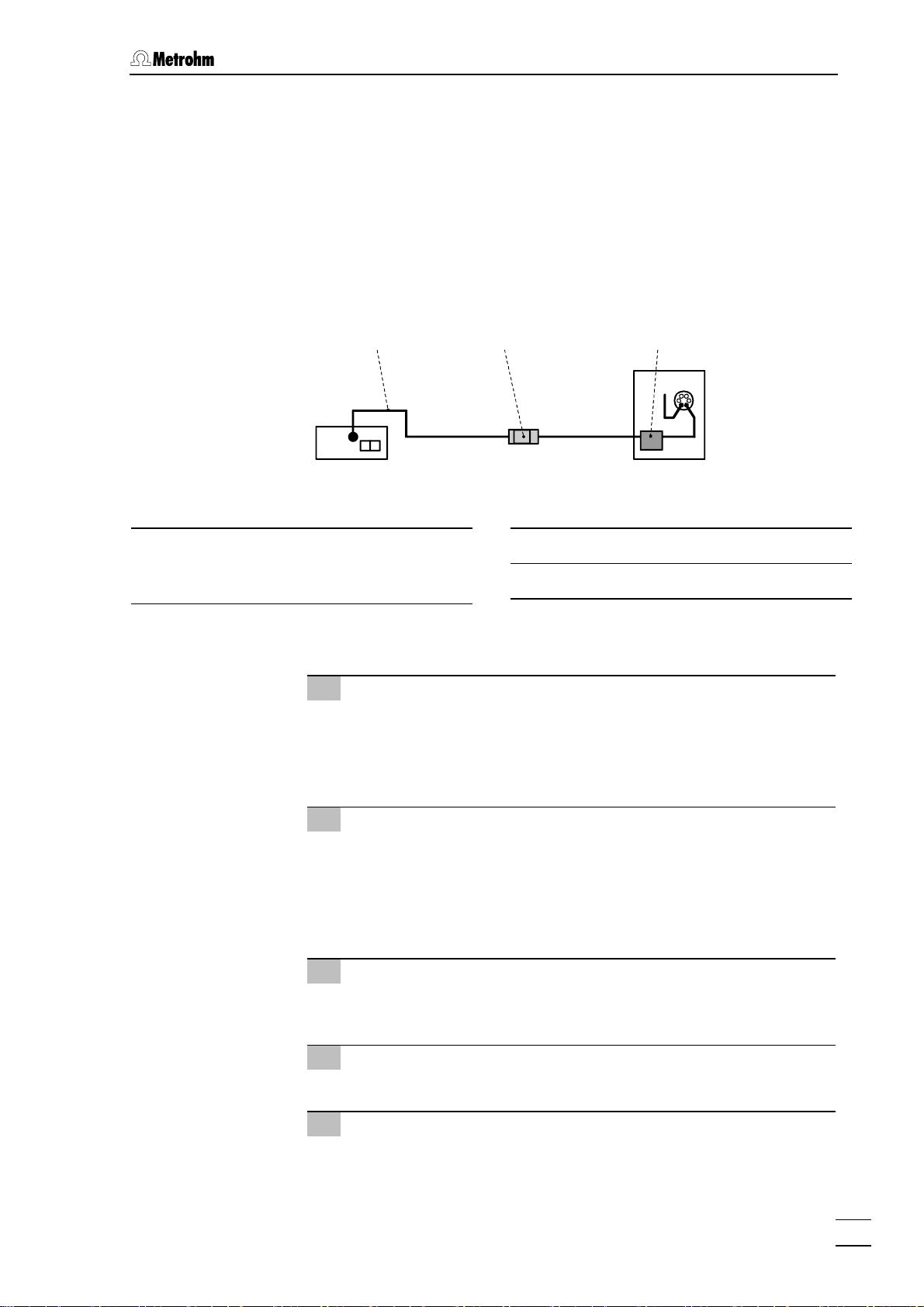
2.5.1 Connection to 830 IC Interface
The 818 IC Pump is normally integrated into the modular IC system via
830 IC Interface. Connect the RS 232 interface 17 of the 818 IC Pump
with a free RS 232 interface at the 830 IC Interface using the 6.2134.080
or 6.2134.090 cable according to the figure below. To ensure proper
functioning of the communication between the 830 IC Interface and 818
IC Pump, the sliding switch 16 on the IC pump must be set to "RS 232".
PC
6.2134.100
830
818
6.2134.080/6.2134.090
CURRENT
LOOP
RS 232
Fig. 6: Connection of 818 IC Pump to 830 IC Interface
818 IC Pump / 8.818.1023 Instructions for Use
13
Page 20

2 Installation
2.5.2 Connection to PC
The 818 IC Pump can also be connected directly to a PC. Connect the
RS 232 interface 17 of the 818 IC Pump with a free COM port at the PC
using the 6.2125.110 (for 9 pin COM port connector) or 6.2125.060
cable (for 25 pin COM port connector) according to the figure below. To
ensure proper functioning of the communication between the PC and
818 IC Pump, the sliding switch 16 on the IC pump must be set to "RS
232".
818
6.2125.110/6.2125.060
CURRENT
LOOP
RS 232
Fig. 7: Connection of 818 IC Pump to PC
14
818 IC Pump / 8.818.1023 Instructions for Use
Page 21

2.6 Mains connection
2.6 Mains connection
Follow the instructions below for connecting to the power supply. If
the instrument is operated with a mains voltage set wrongly and/or
wrong mains fuse, there is a danger of fire!
2.6.1 Setting the mains voltage
Before switching on the 818 IC Pump for the first time, check whether
the mains voltage set on the instrument (can be read in the mains
voltage selector 11) matches the local mains voltage. If this is not the
case, you must switch the mains voltage by pushing the mains voltage
selector 11 with a screwdriver:
Position of the mains
voltage selector 11:
1 Disconnect mains cable
Disconnect mains cable from mains connection plug 10 of the
818 IC Pump.
2 Remove fuse cover
Using a screwdriver, lever out fuse cover 10 forwards until it
opens.
3 Check and change fuses if necessary
Carefully take the fuses installed for the desired mains voltage
out of the fuse holder and check its specifications:
100…120 V 0.5 A (slow blow) Metrohm No. U.600.0013
220…240 V 0.25 A (slow blow) Metrohm No. U.600.0010
Change fuse if necessary and reinsert in fuse holder.
230V
115V
230V: 220…240 V ± 10%
115V: 110…120 V ± 10%
4 Install fuse holder
Reinsert fuse holders in the instrument (the arrows printed on the
holders must point in the same direction as the arrows on the
inside of fuse cover 10).
5 Install fuse cover
Push in fuse cover 10 firmly until it clicks into place.
6 Connect mains cable
Plug mains cable into mains connection plug 10.
818 IC Pump / 8.818.1023 Instructions for Use
15
Page 22

2 Installation
2.6.2 Fuses
The 818 IC Pump contains two fuses built in as standard, either of type
0.25 AT (for 230 V: 0.25 A, slow-blow, Metrohm ordering number
U.600.0010) or 0.5 AT (for 110 V: 0.5 A, slow-blow, Metrohm ordering
number U.600.0013). Ensure that the two fuses correspond to the fuse
type specified for the local mains voltage (see also Fig. 2).
Ensure that the instrument is never put into operation with fuses of
another type, otherwise there is danger of fire!
To change wrong or blown fuses, proceed as described in section
2.6.1.
2.6.3 Mains cable
The instrument is supplied with one of three mains cables:
• 6.2122.020 with plug SEV 12 (Switzerland, …)
• 6.2122.040 with plug CEE(7), VII (Germany, …)
• 6.2133.070 with plug NEMA 5-15 (USA, …)
which are three-cored and fitted with a plug with an earthing pin. If a
different plug has to be fitted, the yellow/green lead (IEC standard)
must be connected to protective earth (protection class 1).
Any break in the earthing inside or outside the instrument can make it
a hazard!
Plug the mains cable into mains connection plug 10 (see Fig. 2).
2.6.4 On/off switching of the instrument
The 818 IC Pump is switched on and off using mains switch 10 (see
Fig. 2). When the instrument is switched on the mains pilot lamp 1 lights
up.
16
818 IC Pump / 8.818.1023 Instructions for Use
Page 23

2.7 Software installation
2.7 Software installation
The PC program «IC Net 2.3» is required for the operation of the 818 IC
Pump. This program runs under Windows 2000 and Windows XP
operating systems and is installed according to section 1.4.2 of the
Instructions for Use 8.110.8283 from the Metrodata software «IC Net
2.3».
The installation of 818 IC Pump is described in section 6.1.2 of the
Instructions for Use 8.110.8283 from the Metrodata software «IC Net
2.3». Take care that the RS 232 settings are identical for the RS 232
interface of 818 IC Pump and 830 IC Interface. For the settings of 818
IC Pump see section 6.10.
2.8 Deaerating the pump
1 Start IC system
Switch the IC instruments on, start «IC Net» and open the
device window
818 IC Pump.
Operation of 818 IC Pump via the software «IC Net 2.3» is described
more detailed in section 3. For further information refer to the
Instructions for Use of «IC Net» and to the online help of the program.
2 Purge pump
The purge valve 2 is opened by turning anticlockwise and the
pump can now be deaerated by starting the pump in «IC Net».
The solvent bottle should be located somewhat above the pump, but
8
at least at the same level as the pump head
pump).
3 Deaerate pump
Should the pump not prime by itself, the 6.2816.020 syringe
supplied is used to siphon off solvent via the outlet capillary 5
with opened purge valve through the pump head until there are
no more bubbles in the solvent entering the syringe. The pump
can then again be briefly purged.
4 Close purge-valve
On completion of this procedure, the purge valve 2 is closed by
turning clockwise. The pump is now ready for operation.
(never below the
818 IC Pump / 8.818.1023 Instructions for Use
17
Page 24

3 Operation
3 Operation
The operation of 818 IC Pump is made completely via the Metrohm
software «IC Net».
This section describes only the most important points concerning the
operation of the 818 IC Pump. For further details please refer to the
«IC Net» Instructions for Use and to the on-line help in the PC
program.
3.1 Switch instrument on/off
The 818 IC Pump is switched on and off using mains switch 10 on the
rear of the instrument (sse Fig. 2). When the instrument is switched on
the mains pilot lamp 1 lights up to show that the instrument is ready for
use.
3.2 818 IC Pump icon
818 IC Pump
3.3 Settings in the "818 IC Pump" window
By double-clicking the 818 icon by clicking this icon with the right
mouse button and selecting the
window for parameter settings is opened. It consists of the four tabs
Settings, Program, Links and Advanced.
Open menu item the 818 IC Pump
18
818 IC Pump / 8.818.1023 Instructions for Use
Page 25

3.3 Settings in the "818 IC Pump" window
Settings
Settings tab of the 818 IC Pump window contains basic settings of
The
the 818 IC Pump.
Pressure Live display of current pressure in MPa.
Flow Live display of current flow in mL/min.
New flow A new flow can be set by moving the scroll bar,
by entering a value or by changing the value
using the up and down arrows.
Entry range:
Min/Max pressure The minimum and maximum pressure limit for
0.01 ... 5.00 mL/min
the 818 IC Pump can be set in steps of 0.1
MPa.
Entry range:
0.0 ... 30.0 MPa.
The set maximum limit value should lie
between 5 to 10 MPa above the particular
operating pressure or the maximum admissible
operating pressure of the column used. If the
pump exceeds the preset limit value during
operation, it is switched off immediately. At the
same time, the
Pressure field color in the 818
settings window is changed to the value set for
Out of range.
The set minimum limit value should lie far
enough below the particular operating
pressure. If the pump pressure falls below this
preset lower limit during operation and this
pressure drop persist for several revolutions of
the pump cam due to leaks or interrupted inflow
of the eluent, the pump is automatically
818 IC Pump / 8.818.1023 Instructions for Use
19
Page 26

3 Operation
switched off. At the same time, the Pressure
field color in the 818 settings window is
changed to the value set for
<Set> Send current parameters immediately to the
Out of range.
818 IC Pump (only available if pump is
running). Parameters are not stored in the
system file (
*.smt) as long as the file is not
saved.
<Start> Set current parameters and start 818 IC Pump
drive.
<Stop> Stop 818 IC Pump drive.
Time program
Program tab of the 818 IC Pump window a user-defined time program
The
can be entered. This program is started automatically as defined in the
Start mode window (see section 4.4.3 «IC Net 2.3» Instructions for Use
8.110.8283), either at the moment the determination is started (
determination
) or at the moment the sample is injected (Start with inject).A
Start with
First column Time at which program instruction is applied.
Entry range:
0.0 ... 999.9 min
If no time is entered, the program instruction is
applied together with the last instruction with
time entry.
Second column Program instruction (see below).
Third column Parameter for program instruction (see below).
20
818 IC Pump / 8.818.1023 Instructions for Use
Page 27

3.3 Settings in the "818 IC Pump" window
ENABLED Enable program start (a disabled program is
not started).
<Add> Add new program instruction.
<Delete> Delete selected program instruction.
<Verify> Test the time program (error messages are
displayed if program is wrong).
List of program instructions
The following program instructions can be added to the time program
on the
Befehl Parametereintrag Bedeutung
Pump on, off Switch the high pressure pump on or
Program page:
off.
Flow 0.01 ... 5 mL/min Set flow rate of the high pressure
pump to the desired value.
Links
Pmax 0.0 ... 30.0 MPa Set maximum pressure limit for the
high pressure pump to the desired
value.
Pmin 0.0 ... 30.0 MPa Set minimum pressure limit for the
high pressure pump to the desired
value.
Die Registerkarte
Einstellung der COM-Schnittstelle (Details siehe section 5.2.4 Links of
the «IC Net 2.3» Instructions for Use 8.110.8283).
Links im Fenster 818 IC Pump dient zur Wahl und
818 IC Pump / 8.818.1023 Instructions for Use
21
Page 28

3 Operation
Advanced
Advanced tab of the 818 IC Pump window is only available for a
The
connected system.
Correction factor Flow correction factor to adjust the displayed
flow to the actual flow measured with the aid of
a measuring cylinder.
Entry range:
Correction factor =
0.90 ... 1.10
Displayed flow rate (in mL/min)
Measured flow rate (in mL/min)
<Set> Send current Correction factor value to the 818
IC Pump. This parameter is not stored in the
system file (
*.smt) as long as the file is not
saved.
The difference between displayed and actual flow rate can be
maximum 3 % owing to unavoidable tolerances in the manufacture of
mechanical parts. Examine therefore the flow rate after
disassembling/assembling of the pump head and adjust the 818 IC
Pump with the correction factor if necessary.
22
818 IC Pump / 8.818.1023 Instructions for Use
Page 29

4.1 Practical notes
4 Notes – Maintenance – Faults
4.1 Practical notes
4.1.1 Protection against foreign particles
To protect the column against foreign particles which could have an
adverse influence on the separation efficiency, we advise you to subject
both the eluents and all samples to microfiltration (0.45 µm filter) and
to siphon the eluent through the 6.2821.090 Aspirating filter.
To avoid contamination by abrasive particles arising from piston seals
of the 818 IC Pump, it is advantageous to install an in-line filter 24
between the pump and the 820 IC Separation Center (see Fig. 5). We
recommend to use the 6.2821.100 Filter unit PEEK which is included
in the standard accessories of the 818 IC Pump (see section 2.3.3).
4.1.2 Pulsation dampener
To protect the column material against pressure shocks caused by
injection we recommend to use a pulsation dampener between the 818
IC Pump and the 820 IC Separation Center (see Fig. 5). The optional
6.2620.150 Pulsation dampener MF (see section 2.3.2) is eminently
suitable for this purpose.
4.1.3 Eluents
Treatment
For the preparation of the eluents one should use chemicals of a purity
degree of at least "p.a.". For dilution please use only high purity water.
Fresh eluents should always be microfiltered (0.45 µm filter) and
degassed (with N
837 IC Eluent Degasser is available from Metrohm. The eluent should
be continuously stirred with a magnetic stirrer, particularly when the
recycling procedure is employed or when alkaline eluents are used. For
alkaline eluents and eluents with low buffering capacity one should
preferably use CO
The supply vessel containing the eluent must be closed as tightly as
possible to avoid excessive evaporation. This is primarily important with
eluents containing organic solvents (e.g. acetone), the evaporation of
which can lead to drifts in the long term. If work is performed in a very
sensitive range, even if one drop of condensate falls back in the eluent
this can cause a noticeable change in the background conductivity.
, He or vacuum). For in-line degassing of eluents the
2
absorbers.
2
Precipitates
Salt crystals between the piston and the seal are the cause of abrasive
particles, which can enter the eluent. These lead to contaminated
818 IC Pump / 8.818.1023 Instructions for Use
23
Page 30

4 Notes – Maintenance – Faults
valves, pressure rise and in extreme cases to scratched pistons. It is
thus essential to ensure that no precipitates can appear, e.g. when
the eluent is changed. Solutions used in direct succession must
therefore be miscible. If the system has to be rinsed with an organic
solution, several solvents with increasing or decreasing lipophilic
character may possibly have to be used (e.g. water ↔ acetone ↔
chloroform).
4.2 Maintenance and servicing
4.2.1 General information
Care
The 818 IC Pump requires proper care and attention. Excessive
contamination of the instrument could possibly lead to malfunctions
and a shorter service life of the inherently rugged mechanical and
electronic parts.
Spilled chemicals and solvents should be wiped up immediately. It is
especially important to protect the plug connections at the rear of the
instrument (particular the mains plug) against contamination.
Although constructional measures have been designed to virtually
eliminate such a situation, should corrosive media penetrate the
interior of the instrument the mains plug of the 818 IC Pump must be
immediately disconnected to prevent extensive damage to the
instrument electronics. Inform Metrohm service if your instrument has
been damaged in such a way.
The instrument must not be opened by untrained personnel. Please
comply with the safety notes in section Fehler! Verweisquelle konnte
nicht gefunden werden..
Maintenance by Metrohm service
Maintenance of the 818 IC Pump is best done as part of an annual
service performed by specialists from the Metrohm company. If work is
frequently performed with caustic and corrosive chemicals, it may be
necessary to shorten the interval between servicing.
The Metrohm service department is always willing to offer expert advice
on the maintenance and servicing of all Metrohm instruments.
24
818 IC Pump / 8.818.1023 Instructions for Use
Page 31

4.2 Maintenance and servicing
4.2.2 Maintenance work at the pump head
In many cases, an unstable baseline (pulsation, flow fluctuations) can
be traced to contaminated valves or faulty, leaky piston seals. For
cleaning contaminated valves and/or replacement of wear parts such
as pistons, piston seals and valves, proceed as follows:
1 Detach pump head
Unscrew connection capillary 6 from the pump head 8 with the
aid of the ¼" wrench (see Fig. 1). Then remove the pump head 8
from the pump housing by loosening the 4 hexagon screws 9
using the 6.2621.030 hexagon key. The main piston is on the left
(when viewed from front), the auxiliary piston on the right.
2 Disassemble pump head
Strip down pump head 8 in accordance with Fig. 8. Main and
auxiliary pistons are identical with the following exceptions:
• The spring 29 of the auxiliary piston (right piston) is more
powerful (longer) than that of the main piston (left piston).
• Inlet and outlet valve are not present in the secondary
cylinder.
To prevent the piston
30
, the screw 26 must be undone very carefully by hand.
27
suddenly jumping out of the piston cartridge
3 Cleaning/replacement of piston 27
Pistons contaminated by abrasive particles or deposits are
cleaned with scouring powder and rinsed free of any particles
with dist. water. Relatively badly contaminated or scratched
pistons must be replaced (spare part: 6.2824.070 Zircon piston).
4 Replacement of piston seal 34
To remove damaged piston seals 34 the special tool 38 is used.
This is screwed into the seal 34, which can then be pulled out
(see Fig. 9A).
When the special tool
is completely destroyed!
38
is screwed into the piston seal
34
the latter
818 IC Pump / 8.818.1023 Instructions for Use
25
Page 32

4 Notes – Maintenance – Faults
A
37
8
36
27 26 34 333229 35
Fig. 8: Components of the pump head
38
28
39
30 31
34
B
C
37
8
34
39
38
Fig. 9: Replacement of the piston seal
26
818 IC Pump / 8.818.1023 Instructions for Use
34
Page 33

4.2 Maintenance and servicing
Pump head 6.2824.100
8
Screw
26
for piston cartridge 30.
Piston with piston shaft (6.2824.070
27
zircon piston or 6.2824.000 sapphire
piston)
Spring retainer
28
Spring (6.2824.050) (for main piston)
29
or
Spring (6.2824.060) (for auxiliary
piston)
Piston cartridge (4.709.0760)
30
Piston guide sleeve (4.709.4380)
31
Sapphire supporting ring
32
To install a new piston seal 34 the special tool 39 is used:
(6.2824.030)
Piston guide sleeve (4.709.4370)
33
Piston seal 6.2741.020
34
Inlet valve (6.2824.090)
35
Outlet valve (6.2824.080)
36
Screw holder for valve.
37
Special tool (6.2617.010) to remove
38
the piston seal 34.
Special tool (6.2617.010) to install
39
the piston seal 34.
• First the new seal is inserted firmly in the recess of tool 39 by
hand (see Fig. 9B). The seal spring must be located on the
outside.
• The tool 39 together with the seal is then inserted in the pump
head 8 and the seal pressed into the pump head recess with
the aid of tool 38 (see Fig. 9C).
The seal surface in the pump head
contact with tool)!
8
must not be damaged (avoid
818 IC Pump / 8.818.1023 Instructions for Use
27
Page 34

4 Notes – Maintenance – Faults
5 Cleaning/Replacement of inlet valve 35 and outlet
valve 36
Contaminated or blocked valves are cleaned by rinsing with dist.
water, RBS solution or acetone. The rinsing effect can be
reinforced by brief treatment in an ultrasonic bath (max. 20 s; if
longer the sapphire sphere of the valve can be damaged).
If this does not have the desired effect, the valves can be
disassembled as shown in Fig. 10. Therefore the valves are
inserted into the holder of 6.2617.020 special tool and the
components of the valve are pushed out with the aid of the push
rod (also included in 6.2617.020 special tool) inserted through
the upper opening in the valve housing 40. The individual
components are rinsed with dist. water and/or acetone, and the
sapphire sphere cleaned with a paper towel. The valve is then
reassembled in accordance with Fig. 10. The components of the
inlet and outlet valves are identical, they are distinguished only
by the positioning of the sapphire sleeve 43 and the ceramic
holder 45 (see Fig. 10).
Valves that fail to function faultlessly after such cleaning must be
replaced.
In the reinstallation of the inlet valve 35 or the outlet valve 36 on
no account must the two outwardly identical valves be
interchanged. To determine which valve is which, note that the
liquid flows through the pump head from the bottom up. The
flow direction of the valves can be checked simply by blowing
through the clean valve. Both valves are installed with the black
face in the direction of the pump head (see Fig. 8).
35
If by mistake an inlet valve
36
, an extreme pressure buildup occurs within the working cylinder,
which is not detected by the pressure transducer and will destroy the
34
piston seal
!
is installed instead of the outlet valve
6 Mounting the pump head
The components of the pump head 8 are reassembled as
shown in Fig. 8. the screw 26 and the piston cartridge 30 may
be tightened only by hand. On the other hand, the two valve
screw holders 37 are tightened with a wrench. The pump head is
then remounted on the pump (see section 2.2).
28
818 IC Pump / 8.818.1023 Instructions for Use
Page 35

4.2 Maintenance and servicing
Inlet valve Outlet valve
6.2824.090 6.2824.080
Valve housing
40
41
42
40
41
42
40
Sealing ring (black)
41
Sleeve
42
Sapphire sleeve
43
The bright side must point towards
the sapphire sphere
Sapphire sphere
44
Ceramic holder for sapphire
45
sphere
43
45
The large recess must point in the
direction of the sapphire sphere
44
45
44
43
Sealing
46
The larger opening must point
outwards
46
46
Fig. 10: Components of inlet valve
35
and outlet valve 36
818 IC Pump / 8.818.1023 Instructions for Use
29
Page 36

4 Notes – Maintenance – Faults
4.3 Faults and malfunctions
If difficulties appear with the IC system during analyses, their causes
are best investigated in the order separating column → 818 IC Pump
→ eluent → 819/820 IC System (see 819/820 Instructions for Use,
section Faults and malfunctions). Several of the malfunctions which may
appear with the 818 IC Pump are listed in the following table with details
of possible causes and countermeasures.
Malfunction Cause Rectification
Baseline with high
noise level, pulsation
Drift of baseline • Thermal equilibrium
Considerable pressure
drop
Considerable pressure
rise
Pump is not recognized
in «IC Net»
• Contaminated pump
values
• Faulty piston seals
• Quality of the pump
does not suffice for the
selected sensitivity
not yet reached
• Leak in system
• Evaporation of organic
solvent in eluent
• Leak in System • Check connections
• Contamination of the
filter in the 6.2821.100
Filter unit PEEK
• No RS connection • Switch instrument on.
• Clean the valves (see
section 4.2.2)
• Replace the piston
seals (see
section 4.2.2)
• Use pulsation
dampener, use more
powerful pump or
lower the sensitivity
• Condition system with
820 heating switched
on
• Check connections
and make leakproof
• Ensure better closure
of eluent supply
vessel, stir
and make leakproof
• Replace 6.2821.130
connector with filter
• Check wiring.
• Check that the
connection specified in
the 818 IC Pump
window (see section
3.3 Links) matches
the actual wiring
30
818 IC Pump / 8.818.1023 Instructions for Use
Page 37

5.1 RS 232 interface
5 Interfaces
5.1 RS 232 interface
5.1.1 Data transmission protocol
The RS 232 interface of the 818 IC Pump is configured as DTE (Data
Terminal Equipment) with the following technical specifications:
• Standard Data interface in accordance with EIA standard
RS 232C (DIN 66020, page 1)
• Baud rate 9600
• Data Bits 8
• Stopp Bits 1
• XON/XOFF off
• Control characters C
• Max. line length 80 characters + C
• Cable For interconnections of the 818 IC Pump with
• Cable length max. ca. 15 m
DEC 13 HEX 0D
R
DEC 10 HEX 0A
L
F
R LF
non-Metrohm units, only a shielded data cable
(e.g. Metrohm D.104.0201) may be used. The
cable shielding must be faultlessly earthed at
both units (pay attention to current loops;
always use star-head earthing). Only
connectors with adequate shielding may be
used (e.g. Metrohm K.210.0001 with
K.210.9004).
818 IC Pump / 8.818.1023 Instructions for Use
31
Page 38

5 Interfaces
5.1.2 Pin assignment
RS 232C interface extern
Transmitted Data (TxD)
If no data transmission takes place, the line is maintained in
the ”ON” condition. Data are sent only when CTS and DSR are
in the ”ON” condition and DCD is in the ”OFF” condition.
Received Data (RxD)
Data are received only when DCD is ”ON”.
Request to Send (RTS)
ON condition: 818 IC Pump is ready to send data.
Clear to Send (CTS)
ON condition: Remote station is ready to receive data.
Data Set Ready (DSR)
ON condition: The transmission line is connected.
Signal Ground (GND)
Data Carrier Detect (DCD)
ON condition: The received signal level is within the tolerance
range (remote station is ready to send data).
Pin 2
Transmitted Data
Pin 3
Received Data
Pin 4
Request to Send
Pin 5
Clear to Send
Pin 6
Data Set Ready
Pin 7
Signal Ground
Pin 8
Data Carrier Detect
Data Terminal Ready (DTR)
ON condition: 818 IC Pump is ready to receive data.
Protective earth
Direct connection from cable connector to protective earth of
the device.
Contact arrangement at the connector
(female) for socket "RS 232" (male)
1 13
Polarity assignment of the signals
• Data lines (TxD, RxD)
Voltage negative (<–3 V): signal status ”ONE”
Voltage positive (>+3 V): signal status ”ZERO”
• Control or message lines (CTS, DSR, DCD, RTS, DTR)
Voltage negative (<–3 V): OFF status
Voltage positive (>+3 V): ON status
In the transition region from +3 V to –3 V, the signal status is
undefined.
Driver 14C88 to EIA RS 232C specification
Connection cables to external devices must
have an appropriate 25-pin connector (female).
Metrohm offers connector sockets (K.210.9004)
and the associated housing (K.210.0001) as an
option for the preparation of such cables.
14 25
Receiver 14C89 to EIA RS 232C specification
No liability whatsoever will be accepted for damage arising from the improper connection of devices.
Pin 20
Data Terminal Ready
32
818 IC Pump / 8.818.1023 Instructions for Use
Page 39

5.2 Control interface
5.2 Control interface
5.2.1 Functions
The 818 IC Pump has the following control inputs and outputs, which
are accessible via the control interface:
Inputs Reduce flow rate via contact
Stop pump via contact
Outputs Contact open, when pump has been stopped
You will find detailed information on these functions in the following
section.
5.2.2 Control inputs and outputs
818 IC Pump external Function
Inputs
+ 5V
100k
1n
4.7k
2
Reduced flow rate (Reduced Flow)
with contact
Contact open: Flow rate 100%
Contact closed: Flow rate 10%
818 IC Pump / 8.818.1023 Instructions for Use
1
33
Page 40

5 Interfaces
818 IC Pump external Function
Inputs
+ 5V
100k
4.7k
8
Stop pump with contact
Contact closed: Pump is stopped
1n
7
Outputs
Pump stopped
Contact open: Pump stopped
Contact closed: Pump running
Relay
3
4
34
818 IC Pump / 8.818.1023 Instructions for Use
Page 41

5.2 Control interface
818 IC Pump external Function
Display of suction phase of the 818
IC Punp
5
6
9
Connection not used
Contact arrangement at connector (male) for socket
"Control" (female)
5 1
96
No liability whatsoever will be accepted for damage arising from the improper connection of devices.
818 IC Pump / 8.818.1023 Instructions for Use
35
Page 42

6 Appendix
6 Appendix
6.1 Technical specifications
Type Serial dual piston with two valves
Pump capacity
Flow range 0.05...5.00 mL/min
Flow accuracy < 1.0 %
Flow constancy < 0.5 % (after unit warmed up)
Reproducibility of
eluent flow
Pressure
Pressure range 0...30.0 MPa (0...300 bar)
Resolution for pressure
indicator
Pressure measurement Piezoresistive measurement principle
Accuracy of pressure
measurement
Residual pulsation < 1 %
Recorder output for
pressure indication
Provided that nothing to the contrary is mentioned, the
published data are typical values for the 818 IC Pump at
an ambient temperature of 25°C.
< 0.1 %
0.1 MPa (1 bar)
Response time: 3 ms
Measurement volume: ca. 50 µL
< 3 %
1 mV/MPa (1 mV/10 bar)
Time constant switchable: HIGH = 20 ms
LOW = 1 s
Safety shutdown
Function Automatic shutdown when upper and lower
pressure limits violated
Maximum pressure limit Adjustable between 0.1...30.0 MPa (1...300 bar)
Response time: 1 pump cycle
Minimum pressure limit Adjustable between 0.1 ... 30.0 MPa (1...300 bar),
inactive at 0 bar
Response time: 3 pump cycles
The cutoff function first becomes active 2 min
after the pump flow has been switched on.
36
818 IC Pump / 8.818.1023 Instructions for Use
Page 43

6.1 Technical specifications
Pump head
Pump head volumes Main piston: 40 µL
Priming piston: 20 µL
Pump displacement volumes Main piston: 28.5 µL
Priming piston: 14.25 µL
Length of stroke Main piston: 3.6 mm
Priming piston: 1.8 mm
Programming
Remote control Flow rate
Maximum and minimum pressure limit values
Correction factor for pump head
Start/Stop
Storage of entries
Type Flash-ROM
Duration > 20 years
Remote control
Interfaces RS 232 (syntax Metrohm, see section 5.1, details
on request)
Current Loop (details on request)
Control (see section 5.2)
RS 232 interface
Standard EIA RS 232C, CCITT V.24, ISO 2110, DIN 66020
Plug
D-Sub 25 pins, male
Mode Full duplex
(simultaneous sending and receiving)
Parameters Baud rate: 9600
Handshake: no Handshake
Parity: none
Stop bits: 1
Data bits: 8
Mains connection
Voltage 115 V: 100...120 V ± 10 %
230 V: 220...240 V ± 10 %
switchable
Frequency 50...60 Hz
Power consumption 50 VA
Fuses Diameter = 5 mm, length = 20 mm
818 IC Pump / 8.818.1023 Instructions for Use
100…120 V: 0.5 A (slow blow)
220…240 V: 0.25 A (slow blow)
37
Page 44

6 Appendix
Safety specifications
Construction / Testing According to EN/IEC 61010-1 / UL 3101-1,
protection class 1, degree of protection IP40
Safety directions This Instructions for Use include information and
warnings which must be heeded by the user to
assure safe operation of the instrument.
Electromagnetic compatibility (EMC)
Emitted interference Standards met:
- EN/IEC 61326
- EN 55022
- CISPR 22
Immunity to interference Standards met:
- EN/IEC 61326
- EN/IEC 61000-4-2
- EN/IEC 61000-4-3
- EN/IEC 61000-4-4
- EN/IEC 61000-4-5
- EN/IEC 61000-4-6
- EN/IEC 61000-4-11
- EN/IEC 61000-4-14
- NAMUR
Ambient temperature
Nominal operating range +5…+45°C
(at 5…85 % atmospheric humidity)
Storage, transport –20…+70°C
Diagnosis
Self-diagnostic test Automatic self-diagnosis when instrument
switched on
Materials (in contact with solvent)
Sapphire, ruby, ceramic, PCTFE, PTFE, PEEK
Housing
Material of cover Polyurethane rigid foam (PUR) with fire protection
for fire class UL94VO, FCH-free
Material of base Steel enamelled
Width 260 mm
Height 130 mm
Depth 385 mm (with pump head)
Weight 10 kg (incl. accessories)
38
818 IC Pump / 8.818.1023 Instructions for Use
Page 45

6.2 Scope of delivery
⁄
6.2 Scope of delivery
Subject to changes !
All dimensions are given in mm.
The IC Pump 2.818.0110 (metal-free) includes the following parts:
Quant. Order No. Description
1 6.1831.010 PEEK capillary
Length = 3 m
1 6.1834.000 Aspirating tubing
made of PTFE, with connector for
6.2821.090 Aspirating filter
Length = 1.2 m
For the connection 818 IC Pump –
eluent container
1 6.2122.0X0 Mains cable
according to customer's specification:
Cable socket Cable plug
Type IEC 320/C 13 Type SEV 12 (CH…)............................... 6.2122.020
Type IEC 320/C 13 Type CEE (7), VII (D…)........................... 6.2122.040
Type CEE (22), V Type NEMA 5-15 (USA…) ...................... 6.2122.070
0.25
1
16"
2.51.5
1 6.2617.010 Special tool
For removing the piston seal of the
pump head
1 6.2621.000 Adjustable spanner
1 6.2621.030 Hexagon key 4 mm
For mounting the pump head of the
818 Pump.
1 6.2744.010 PEEK compression fitting
For the connection of 6.1831.010
PEEK capillaries
Set of 5
35 50
max.
20
73
150
M3.5
29.5
26
818 IC Pump / 8.818.1023 Instructions for Use
39
Page 46

6 Appendix
Quant. Order No. Description
1 6.2816.020 Syringe
made of PP, volume = 10 mL
with Luer connector
1 6.2816.040 Tubule
with PTFE tubing and Luer connection
For 6.2816.020 syringe
1 6.2821.090 Aspirating filter
Pore dimension 20 µm
For 6.1834.000 Aspirating tubing.
Set of 5
1 6.2821.120 Filter unit PEEK 2 µm
To avoid contamination due to
abrasive particles of piston seals
Spare part: 6.2821.130 Filter
1 6.2824.100 Pump head PEEK (metal-free)
Complete, with fixation screws
102
120
∅9
35
11
54
1 8.818.1023 Instructions for Use (English)
for 818 IC Pump
40
818 IC Pump / 8.818.1023 Instructions for Use
Page 47

6.3 Optional accessories
6.3 Optional accessories
Order No. Description
6.1834.010 Aspirating tubing
made of PTFE, with connector for 6.2821.090
Aspirating filter
Length = 2.5 m
For the connection 818 IC Pump – eluent
vessel of 6.5324.000 Bottle rack
6.2620.150 Pulsation dampener MF
Metal-free pulsation dampener for reduction of
pulsation and preservation of separating
columns.
2.51.5
6.2621.080 Capillary tubing cutter
for 6.1831.010 PEEK capillaries and
6.1822.010 PTFE micro capillaries
incl. 5 additional blades
6.2741.020 Piston seal PE
Spare part for 6.2824.100 pump head
(standard seal)
6.2741.010 Piston seal PE
Spare part for 6.2824.100 pump head
(only suitable for aqueous eluents)
6.2744.070 PEEK compression fitting (short)
Spare part for 6.2824.100 pump head
Set of 5
55
118
6.5
6.5
21
3
3
6.2821.130 Filter for filter unit PEEK 2 µm
Spare part for 6.2821.120 Filter unit PEEK
Set of 10
6.2824.070 Zircon piston
Spare part for 6.2824.040 and
6.2824.100 pump head
818 IC Pump / 8.818.1023 Instructions for Use
∅3
65.5
41
Page 48

6 Appendix
Order No. Description
6.2824.030 Sapphire supporting ring
Spare part for 6.2824.100 pump head
6.2824.050 Spring for main piston
Spare part for 6.2824.100 pump head
6.2824.060 Spring for auxiliary piston
Spare part for 6.2824.100 pump head
6.2824.080 Outlet valve
Spare part for 6.2824.100 pump
head
6.2824.090 Inlet valve
Spare part for 6.2824.100 pump
head
1.3
∅3.2
∅6.3
30
47
16
∅11
∅11
∅8
∅8
6.2617.020 Special tool
For dismantling the valves
6.5324.000 Bottle rack
For fixing 3 supply bottles for elent,
regeneration and rinsing solution, incl.
accessories (bottles, siphon, etc.)
6.2115.040 Connection cable
For the connection 818 IC Pump – recorder
For plotting curves delivery vs time.
6.2134.080 RS 232 connection cable
Connection cable 818 IC Pump – 830 IC
Interface
6.2134.090 RS 232 connection cable
Connection cable 830 IC Interface –
2 external devices (818, 819, etc.)
16
42
818 IC Pump / 8.818.1023 Instructions for Use
Page 49

6.3 Optional accessories
Order No. Description
6.2125.110 RS 232 connection cable
Connection cable 818 IC Pump – PC)
6.2125.060 RS 232 connection cable
Connection cable 818 IC Pump – PC.
818 IC Pump / 8.818.1023 Instructions for Use
43
Page 50

6 Appendix
6.4 Validation / GLP
GLP (Good Laboratory Practice) requires, among other things, that the
precision and correctness of analytical instruments is checked at
regular intervals by using SOPs (Standard Operating Procedures,
SOP). An example of such a standard operating procedure is available
from Metrohm under the title «Application Bulletin No. 277 –
Validation of Metrohm Ion Chromatography Systems by using
Standard Operating Procedures (SOP)». This SOP can be adapted
for your ion chromatography system and used for its validation.
The 818 IC Pump must be included as a part of the whole ion
chromatography system, whose most important components include
pumps, separation columns, detector and evaluation system, in the allembracing validation of the whole system.
Please contact your local Metrohm agency in order to receive support
in validating your 818 IC Pump. It can also provide you with validation
documentation which will help you to carry out your installation
qualification (IQ) and operational qualification (OQ).
Further information about QA, GLP and validation can also be found in
the brochure «Quality management with Metrohm» which is also
obtainable from your local Metrohm agency.
Checking the electronic and mechanical assemblies of Metrohm
instruments can and should be undertaken within the framework of
regular servicing by Metrohm technicians. All Metrohm instruments are
equipped with start-up check routines which check that the relevant
assemblies are functioning perfectly when the instrument is switched
on. If no error message appears it can be assumed that the instrument
is functioning properly.
The 818 IC Pump also contains a built-in diagnosis program which
allows the service technicians to check the functioning of particular
assemblies should faults or malfunctions occur and to localize them.
44
818 IC Pump / 8.818.1023 Instructions for Use
Page 51

6.5 Warranty and Conformity
6.5 Warranty and Conformity
6.5.1 Warranty
The warranty on our products is limited to defects that are traceable to
material, construction or manufacturing error which occur within 12
months from the day of delivery. In this case, the defects will be
rectified in our workshops free of charge. Transport costs are to be paid
by the customer.
For day and night operation, the warranty is limited to 6 months.
Glass breakage in the case of electrodes or other parts is not covered
by the warranty. Checks which are not a result of material or
manufacturing faults are also charged during the warranty period. For
parts of outside manufacture insofar as these constitute an appreciable
part of our instrument, the warranty stipulations of the manufacturer in
question apply.
With the regard to the guarantee of accuracy, the technical
specifications in the instruction manual are authoritative.
Concerning defects in material, construction or design as well as the
absence of guaranteed features, the orderer has no rights or claims
except those mentioned above.
If damage of the packaging is evident on receipt of a consignment or if
the goods show signs of transport damage after unpacking, the carrier
must be informed immediately and a written damage report demanded.
lack of an official damage report releases Metrohm from any liability to
pay compensation.
If any instruments and parts have to be returned, the original packaging
should be used if at all possible. This applies above all to instruments,
electrodes, burette cylinders and PTFE pistons. Before embedment in
wood shavings or similar material, the parts must be packed in a
dustproof package (for instruments, use of a plastic bag is imperative).
If open assemblies are enclosed in the scope of delivery that are
sensitive to electromagnetic voltages (e.g. data interfaces etc.) these
must be returned in the associated original protective packaging (e.g.
conductive protective bag). (Exception: assemblies with built-in voltage
source belong in a non-conductive protective packaging).
No warranty responsibility whatsoever will be accepted by Metrohm for
damage which arises as a result of non-compliance with these
instructions.
818 IC Pump / 8.818.1023 Instructions for Use
45
Page 52

6 Appendix
6.5.2 Declaration of Conformity
This is to certify the conformity to the standard
specifications for electrical appliances and accessories,
as well as to the standard specifications for security and
to system validation issued by the manufacturing
company.
Name of commodity 818 IC Pump
System software Stored in ROMs
Name of manufacturer Metrohm Ltd., Herisau, Switzerland
Description
Dual piston pump for use in Ion Chromatography (IC) and
High Performance Liquid Chromatography (HPLC).
This Metrohm instrument has been built and has undergone final type testing according to the
standards:
CH-9101 Herisau, Switzerland
Tel. +41 71 353 85 85
Fax +41 71 353 89 01
www.metrohm.com
Electromagnetic compatibility: Emission
EN/IEC 61326, EN 55022 / CISPR 22
Electromagnetic compatibility: Immunity
EN/IEC 61326, EN/IEC 61000-4-2, EN/IEC 61000-4-3, EN/IEC 61000-4-4, EN/IEC 61000-4-5, EN/IEC
61000-4-6, EN/IEC 61000-4-11, EN/IEC 61000-4-14, NAMUR
Safety specifications
EN/IEC 61010-1, UL 3101-1 protection class I
It has also been certified by ElectroSuisse, which is member of the International Certification Body
(CB/IEC).
The instrument meets the requirements of the CE mark as contained in the EU directives 89/336/EEC
and 73/23/EEC and fulfils the following specifications:
EN 61326 Electrical equipment for measurement, control and laboratory use – EMC requirements
EN 61010-1 Safety requirements for electrical equipment for measurement, control and laboratory
use
Metrohm Ltd. is holder of the SQS-certificate of the quality system ISO 9001 for quality assurance in
design/development, production, installation and servicing.
The system software, stored in Read Only Memories (ROMs) has been validated in connection with
standard operating procedures in respect to functionality and performance.
The technical specifications are documented in the instruction manual.
Herisau, May 28, 2003
Dr. J. Frank Ch. Buchmann
Development Manager Production and
Quality Assurance Manager
46
818 IC Pump / 8.818.1023 Instructions for Use
Page 53

6.5 Warranty and Conformity
6.5.3 Quality Management Principles
Metrohm Ltd., CH-9101 Herisau, Switzerland
CH-9101 Herisau/Switzerland
E-Mail info@metrohm.com
Internet www.metrohm.com
Metrohm Ltd. holds the ISO 9001 Certificate, registration number 10872-02, issued by
SQS (Swiss Association for Quality and Management Systems). Internal and external
audits are carried out periodically to assure that the standards defined by Metrohm’s QM
Manual are maintained.
The steps involved in the design, manufacture and servicing of instruments are fully
documented and the resulting reports are archived for ten years. The development of
software for PCs and instruments is also duly documented and the documents and
source codes are archived. Both remain the possession of Metrohm. A non-disclosure
agreement may be asked to be provided by those requiring access to them.
The implementation of the ISO 9001
quality system is described in Metrohm’s
QM Manual, which comprises detailed
instructions on the following fields of
activity:
Instrument development
The organisation of the instrument
design, its planning and the intermediate
controls are fully documented and
traceable. Laboratory testing
accompanies all phases of instrument
development.
Software development
Software development occurs in terms of
the software life cycle. Tests are
performed to detect programming errors
and to assess the program’s
functionality in a laboratory environment.
Components
All components used in the Metrohm
instruments have to satisfy the quality
standards that are defined and
implemented for our products. Suppliers
of components are audited by Metrohm
as the need arises.
Manufacture
The measures put into practice in the
production of our instruments guarantee
a constant quality standard. Production
planning and manufacturing procedures,
maintenance of production means and
testing of components, intermediate and
finished products are prescribed.
Customer support and service
Customer support involves all phases of
instrument acquisition and use by the
customer, i.e. consulting to define the
adequate equipment for the analytical
problem at hand, delivery of the
equipment, user manuals, training, aftersales service and processing of
customer complaints. The Metrohm
service organisation is equipped to
support customers in implementing
standards such as GLP, GMP, ISO 900X,
in performing Operational Qualification
and Performance Verification of the
system components or in carrying out
the System Validation for the quantitative
determination of a substance in a given
matrix.
818 IC Pump / 8.818.1023 Instructions for Use
47
Page 54

6 Appendix
6.6 Index
8
818 IC Pump
Advanced...................................22
Links ...........................................21
program .....................................20
program instructions.................. 21
830 IC Interface
Connection................................. 13
A
Abrasive particles ..........................23
<Add>............................................21
Adjustable spanner (6.2621.000) .. 39
Ambient temperature ..................... 38
Appendix ........................................ 36
Arrangement of the instruments ...... 7
Aspirating capillary 7
Figure ........................................... 2
Mounting the suction tubing......12
Aspirating filter (6.2821.090)
Mounting .................................... 12
Ordering designation ................. 40
Practical notes ...........................23
Aspirating tubing (6.1834.000) ........9
Mounting .................................... 12
Ordering designation ................. 39
Aspirating tubing (6.1834.010)
Mounting .................................... 12
Ordering designation ................. 41
Attaching the accessories ...............9
Attention ........................................... 5
B
Baud rate ........................................31
Bottle rack (6.5324.000)
Mount aspirating tubing............. 12
Ordering designation ................. 42
C
Cable
6.2115.040 ................................ 42
6.2121.110 .................................43
6.2125.060 ...........................14, 43
6.2125.110 .................................14
6.2134.000 .................................42
6.2134.080 ...........................13, 42
6.2134.090 .................................13
Capillaries ........................................9
Capillary tubing cutter
(6.2621.080)...............................9, 41
Care................................................24
CE mark .........................................46
Ceramic holder 45
Figure ......................................... 29
Check ............................................... 7
Compression fitting 20
6.2744.010 .............................9, 10
Mounting ...................................... 9
Ordering designation ................. 39
Connecting the tubing ...................11
Connection
830 IC Interface.......................... 13
Modular IC system..................... 13
PC...............................................14
Connection capillary 3
Connection 818 – 820................11
Figure ...........................................2
Mounting ....................................11
Connection capillary 4
Figure ...........................................2
Connection capillary 6
Detaching ...................................25
Figure ...........................................2
Fixing at the pump head ..............8
Connections
Figure ...........................................3
Technical specifications ....... 36 ff
Connectors for capillaries ................9
Contents ............................................I
Control characters..........................31
Control inputs .......................... 33, 34
Control interface 13
Figure ...........................................3
Functions....................................33
Control outputs ..............................34
Correction factor.............................22
Current Loop
selector 16
Figure.....................................3
Current Loop interface 18
Figure ...........................................3
D
Danger..............................................5
Data transmission protocol............31
Deaerating the pump .....................17
Declaration of Conformity ..............46
Degassing of the eluent .................23
Degree of protection ................. 6, 38
<Delete> ........................................21
Dimensions ....................................38
Drift .......................................... 23, 30
E
Earthing ..................................... 6, 16
Electrical connection ......................13
Electrical safety ................................6
Electromagnetic compatibility .......38
Eluent container .............................12
Eluents............................................23
EMC................................................38
Emitted interference .......................38
ENABLED ........................................21
Evaporation ............................. 23, 30
External control
selector 16
Figure.....................................3
F
Fastening screws 9
Detach pump head ....................25
Figure ...........................................2
Mounting the pump head ............8
Faults....................................... 23, 30
Figures
list .................................................II
Filter 22
Ordering designation ................ 41
Filter unit PEEK 24
Connection ................................ 11
Ordering designation ................ 40
Filter unit PEEK 6.2821.120
24 ............................................... 11
Connector.................................. 10
Figure......................................... 10
Filter ........................................... 10
Housing ..................................... 10
Mounting.................................... 10
Flow.......................................... 19, 21
Flow accuracy ................................ 36
Flow constancy ............................. 36
Flow range...................................... 36
Front................................................. 2
Fuse cover 10
Figure........................................... 3
Open.......................................... 15
Fuses
Exchange................................... 16
Technical specifications ............ 37
G
General information on
maintenance .................................. 24
General safety rules ........................ 6
GLP .......................................... 44, 47
GMP............................................... 47
H
Handling of solvents........................ 6
Hexagon key (6.2621.030) ...... 25, 39
Housing ......................................... 38
I
IC Net
no connection............................ 30
Immunity to interference................ 38
Information....................................... 5
Information on the Instructions
for Use ............................................. 4
Inlet valve 35
Cleaning .................................... 28
Components.............................. 29
Figure................................... 27, 29
Ordering designation ................ 42
Replacement ............................. 28
Installation........................................ 7
Installing the filter unit PEEK ......... 10
Instructions for Use
(8.818.1023) .............................. 4, 40
Instrument
Switch on/off.............................. 18
Instrument description .................... 1
Interface
Control 13
Figure ....................................3
Current Loop 18
Figure ....................................3
Recorder 14
Figure ....................................3
RS 232 17
818 IC Pump / 8.818.1023 Instructions for Use
48
Page 55

6.6 Index
Figure .................................... 3
Interfaces ....................................... 31
Introduction ..................................... 1
IQ ................................................... 44
ISO 9100........................................ 46
L
Leakage ....................................... 30
Leaks ........................................... 6, 7
Links............................................... 21
List of figures ....................................II
List of program instructions .......... 21
Location ........................................... 7
M
Mains cable ................................... 16
Ordering designation ................ 39
Mains connection ...................... 6, 15
Technical specifications ............ 37
Mains connection plug 10
Mains connection ...................... 16
Mains connector 10
Figure........................................... 3
Mains frequency ............................ 37
Mains pilot lamp 1
Figure........................................... 2
Operating display ................ 16, 18
Mains switch 10
Figure........................................... 3
Switching the instrument
on/off ................................... 16, 18
Mains voltage
Setting........................................ 15
Technical specifications ............ 37
Mains voltage selector 11
Figure........................................... 3
Setting the mains voltage ......... 15
Maintenance ............................ 23, 24
Malfunctions .................................. 30
Materials ........................................ 38
Maximum pressure limit ................ 36
Metrohm service............................ 24
Microfiltration ................................. 23
Min/Max pressure........................... 19
Minimum pressure limit ................. 36
Mounting the pump head ............... 8
N
New flow......................................... 19
No connection ............................... 30
Noise.............................................. 30
Notation ........................................... 5
Notes ............................................. 23
O
Opening the instrument .................. 6
Operation
Via .............................................. 18
Optional accessories .................... 41
OQ ................................................. 44
Ordering designations .................. 39
Organization .................................... 4
Outlet capillary 5
Figure........................................... 2
Deaerating the pump ................ 17
Outlet valve 36
Cleaning..................................... 28
Components .............................. 29
Figure................................... 27, 29
Ordering designations............... 42
Replacement ............................. 28
P
Packaging ........................................ 7
Parts and controls ........................... 2
PC
Connection ................................ 14
PEEK capillary (6.1831.010)...... 9, 39
PEEK capillary 19
6.1831.010 ....................... 9, 10, 11
PEEK capillary 3
6.1831.010 ................................. 11
PEEK compression fitting
(6.2744.070)
Ordering designation................. 41
Pictograms....................................... 5
Piston 27
Cleaning..................................... 25
Figure......................................... 27
Replacement ............................. 25
Piston cartridege 30
Figure......................................... 27
Tighten ....................................... 28
Piston guide sleeve 31
Figure......................................... 27
Piston guide sleeve 33
Figure......................................... 27
Piston seal 34
Figure......................................... 27
Ordering designations............... 41
Replacement ............................. 25
Pmax............................................... 21
Pmin ...............................................21
Power consumption....................... 37
Practical notes ...............................23
Precipitates ....................................23
Pressure ................................... 19, 36
Pressure drop ................................ 30
Pressure measurement...................36
Pressure range ..........................8, 36
Pressure rise .................................. 30
Program .........................................20
818 time program ...................... 20
Protection against foreign
particles ......................................... 23
Protection class .........................6, 38
Pulsation ........................................30
Pulsation dampener
Connection .................................. 9
Pulsation dampener 25
Connection ................................ 11
Ordering designation................. 41
Practical notes ...........................23
Pump.............................................. 21
Icon ............................................18
Pump capacity............................... 36
Pump head 8
Components .............................. 26
Disassemble .............................. 25
Figure..................................... 2, 27
Maintenance ..............................25
Mounting................................ 8, 28
Ordering designation................. 40
Technical specifications ............37
Pump stopped ............................... 34
Purge valve 2
Connection to the pump head ....8
Deaerating the pump.................17
Figure ...........................................2
Q
QA ..................................................44
Quality assurance ..........................44
Quality Management .....................47
R
Rear..................................................3
Recorder output 14
Figure .......................................... 3
Recorder output socket 14
Technical data ...........................36
Recycling........................................23
Reduced flow rate ..........................33
Remote control ..............................37
Residual pulsation .........................36
RS 232
selector 16
Figure.....................................3
settings....................................... 17
RS 232 interface 17
Baud rate....................................31
Data transmission protocol .......31
Figure ...........................................3
Pin assignment ..........................32
Technical specifications ............37
S
Safety notes .....................................6
Safety rules ......................................6
Safety shutdown ............................36
Safety specifications ...................... 38
Sapphire sleeve 43
Figure ......................................... 29
Sapphire sphere 44
Figure ......................................... 29
Sapphire supporting ring 32
Figure ......................................... 27
Ordering designation ................. 42
Scope of delivery ...........................39
Screw 26
Figure ......................................... 27
Tighten .......................................28
Screw holder 37
Figure ......................................... 27
Tighten .......................................28
Sealing 46
Figure ......................................... 29
Sealing ring 41
Figure ......................................... 29
Serial number 12
Figure ...........................................3
Service............................................24
Servicing.........................................24
<Set>.......................................20, 22
Setting up the instrument ................ 7
Settings ....................................18, 19
Sleeve 42
Figure ......................................... 29
Software installation ....................... 17
SOP ................................................44
Special tool (6.2617.020)
Dismantle valve..........................28
818 IC Pump / 8.818.1023 Instructions for Use
49
Page 56

6 Appendix
Ordering designation ................. 42
Special tool 38
Figure ......................................... 27
Ordering designation ................. 39
Remove piston seal 34.............. 25
Special tool 39
Figure ......................................... 27
Install piston seal 34 .................. 27
Ordering designation ................. 39
Spilled chemicals...........................24
Spring 29
6.2824.050
Figure...................................27
6.2824.060
Figure...................................27
Ordering designation ................. 42
Spring retainer 28
Figure ......................................... 27
Standard operating procedures ....44
<Start> ..........................................20
Static charges ..................................6
Stirring of the eluent.......................23
Stop pump .....................................34
<Stop>...........................................20
Storage ...........................................38
Sunlight.............................................7
Switch
External control 16
Figure.....................................3
Time Constant 15
Figure.....................................3
Switch instrument on/off ......... 16, 18
Syringe (6.2816.020)......................17
Ordering designation .................40
T
Technical specifications.................36
Time Constant
switch 15
Figure.....................................3
Transport ..........................................7
Transport damage .........................45
Transport safeguard block ..............8
Treatment of Eluents ......................23
Tubing connections
Connection to eluent container. 12
Connection to injection valve.... 11
Tubule (6.2816.040)
Ordering designation ................ 40
V
Validation ....................................... 44
Valve housing 40
Figure......................................... 29
<Verify> ........................................ 21
W
Warning............................................ 5
Warranty......................................... 45
Z
Zircon piston (6.2824.070) ...... 25, 41
818 IC Pump / 8.818.1023 Instructions for Use
50
 Loading...