

Page 1

817 Bioscan
Bioscan817
Bioscan
CH-9101 Herisau/Switzerland
E-Mail info@metrohm.com
Internet www.metrohm.com
Instructions for Use
8.817.1003
Page 2

Page 3

CH-9101 Herisau/Switzerland
E-Mail info@metrohm.com
Internet www.metrohm.com
817 Bioscan
Instructions for Use
8.817.1003 09.2001 / up
Page 4

Page 5

Contents
Contents
1 Introduction............................................................................................ 1
1.1 Instrument description............................................................................. 1
1.2 Parts and controls .................................................................................... 2
1.3 Information about the Instructions for Use .......................................... 8
1.3.1 Organization.................................................................................. 8
1.3.2 Notation and pictograms.............................................................. 9
1.4 Safety notes ............................................................................................. 10
1.4.1 Electrical safety........................................................................... 10
1.4.2 General precautionary rules ....................................................... 10
2 Installation........................................................................................... 11
2.1 Setting up the instruments.................................................................... 11
2.1.1 Packaging ................................................................................... 11
2.1.2 Check.......................................................................................... 11
2.1.3 Location ...................................................................................... 12
2.1.4 Arrangement of the instruments................................................. 12
2.2 Mains connection ................................................................................... 12
2.2.1 Setting the mains voltage ........................................................... 12
2.2.2 Fuses .......................................................................................... 13
2.2.3 Mains cable and mains connection ........................................... 14
2.2.4 On/Off switching ......................................................................... 14
2.3 Capillary connections ............................................................................ 15
2.3.1 Connection of the 6.5324.000 Bottle Rack (option)................... 15
2.3.2 Connection of the pulsation absorber........................................ 15
2.3.3 Connection of the injection valve ............................................... 16
2.3.4 Mounting the column.................................................................. 16
2.3.5 Connection of the flow cell ......................................................... 17
2.3.6 Connecting the waste tubing...................................................... 18
2.3.7 Rinsing the tubing....................................................................... 19
2.3.8 Rinsing the column ..................................................................... 19
2.4 System for sugar analysis – MIC 8 ...................................................... 20
2.4.1 Electrical connections................................................................. 20
2.4.2 Settings in «IC Net 2.1» ............................................................. 21
2.4.3 Connecting a sample changer ................................................... 22
2.5 System for the analysis of anions and sugars – MIC 9.................... 24
2.5.1 Electrical connections................................................................. 24
2.5.2 Capillary connections ................................................................. 25
2.5.3 Configuration in «IC Net 2.1» ..................................................... 27
2.6 Preparing the 817 Bioscan for the analysis ....................................... 32
2.6.1 System switch-on........................................................................ 32
2.6.2 Start pump .................................................................................. 32
2.6.3 Set operating mode.................................................................... 33
817 Bioscan
I
Page 6

Contents
3 Operation............................................................................................... 35
3.1 Handling the 817 Bioscan ..................................................................... 35
3.2 Operation using «IC Net 2.1» ................................................................ 36
3.2.1 817 Bioscan icon.........................................................................36
3.2.2 817 Bioscan window ...................................................................37
4 Basic principles............................................................................. 47
4.1 Introduction ............................................................................................. 47
4.2 Measuring conditions ............................................................................ 48
4.3 Pulsed amperometric detection........................................................... 49
4.3.1 Optimization of the PAD parameters ..........................................49
4.4 Optimization of the measuring potential ............................................ 51
5 Notes – Maintenance – Faults....................................... 55
5.1 Practical notes on ion chromatography ............................................. 55
5.1.1 Separating columns ....................................................................55
5.1.2 High-pressure pump ...................................................................56
5.1.3 Eluents .........................................................................................57
5.1.4 Connections ................................................................................57
5.2 Maintenance and servicing................................................................... 58
5.2.1 General information .....................................................................58
5.2.2 Shutdown.....................................................................................58
5.2.3 Cleaning the working electrode ..................................................59
5.2.4 Changing separating columns....................................................60
5.3 Faults and malfunctions ........................................................................ 61
5.3.1 Malfunctions and their rectification .............................................61
5.4 Instrument test with the dummy cell ................................................... 63
5.5 Validation / GLP ...................................................................................... 64
6 Appendix................................................................................................. 65
6.1 Technical data......................................................................................... 65
6.2 Standard equipment............................................................................... 69
6.3 Warranty and conformity....................................................................... 71
6.3.1 Warranty.......................................................................................71
6.3.2 EU declaration of conformity.......................................................72
6.3.3 Certificate of conformity and system validation ..........................73
6.4 Index ......................................................................................................... 75
II
817 Bioscan
Page 7

Contents
List of illustrations
Fig. 1: Front of the 817 Bioscan................................................................................... 3
Fig. 2
: Rear of the 817 Bioscan.................................................................................... 4
Fig. 3
: Interior of the 817 Bioscan (with permanently attached accessories) .. 6
Fig. 4
: Setting the mains voltage ............................................................................... 13
Fig. 5
: Connections at the injection valve of the 2.812.0010 Valve Unit ......... 16
Fig. 6
: Connections at flowcell ............................................................................... 17
Fig. 7
: Connecting up a simple modular IC system
with the 817 Bioscan – MIC 8
Fig. 8
: Connecting up a simple MIC 8 system
including a sample changer
Fig. 9
: Connections with a 817 Bioscan as second detector
with a modular IC system – MIC 9
..................................................................... 20
....................................................................... 22
............................................................. 24
Fig. 10
: Connections of injection valves A and B in the IC Separation
Center (2.733.0120)
Fig. 11
: Potentials applied during pulsed amperometric detection (PAD). ...... 49
Fig. 12
: Example of a hydrodynamic voltammogram of a
..................................................................................... 26
substance (A) with additional presentation of the
measured values for the pure eluent (B)
Fig. 13
: Example of a scan of a substance (A) with additional
presentation of the scan of the pure eluent (B)
.................................................. 51
...................................... 52
817 Bioscan
III
Page 8

Contents
IV
817 Bioscan
Page 9
1.1 Instrument description
1 Introduction
1.1 Instrument description
The 2.817.0010 Bioscan is a PC-controlled measuring instrument for
the sensitive analysis of carbohydrates by ion chromatography using
pulsed amperometric detection. The compact housing of the 817 Bioscan contains several IC system components:
• Detector – flow-through cell with three-electrode arrangement for
amperometric detection in the Pulse, DC and Scan modes.
• Column compartment – the perfect insulation of the housing cre-
ates not only stable thermal conditions for the separating columns,
but also shields the system from electromagnetic interference; in
addition to the column it also contains the detection cell, pulsation
absorber and preheating capillary.
• Oven – amperometric determinations require extremely stable
thermal conditions. The built-in column compartment oven ensures
that all important components can be set exactly to a temperature
from 10°C above room temperature to 60 °C with a stability of
0.1°C.
• All components that come into contact with the eluent and the
sample, except the electrodes, are metal-free.
• Signal converter – the 817 Bioscan contains its own analog/ digi-
tal converter for the detector signal. This means that complete control of the instrument is possible from a PC via an RS232 interface.
Together with the 709 IC Pump and the 812 Valve Unit, the 817 Bio-
scan forms a complete IC system for carbohydrate analysis. Operation is via a PC connected to the RS232 interface and uses the in-
cluded «IC Net 2.1» control and evaluation program. This software
fulfills all the demands which are placed today on a modern integration
software: 1-point or multi-point calibration, internal or external standard,
selectable algorithms for non-linear calibration, numerous Integration
modes with selectable parameters and integration events, various peak
recognition methods, peak editor, free scaling, superimposition of several chromatograms, post-treatment of chromatograms, high-performance GLP-conform report generator with output interfaces for monitor,
printer and external databases.
817 Bioscan
1
Page 10

1 Introduction
817 Bioscan
2
Page 11

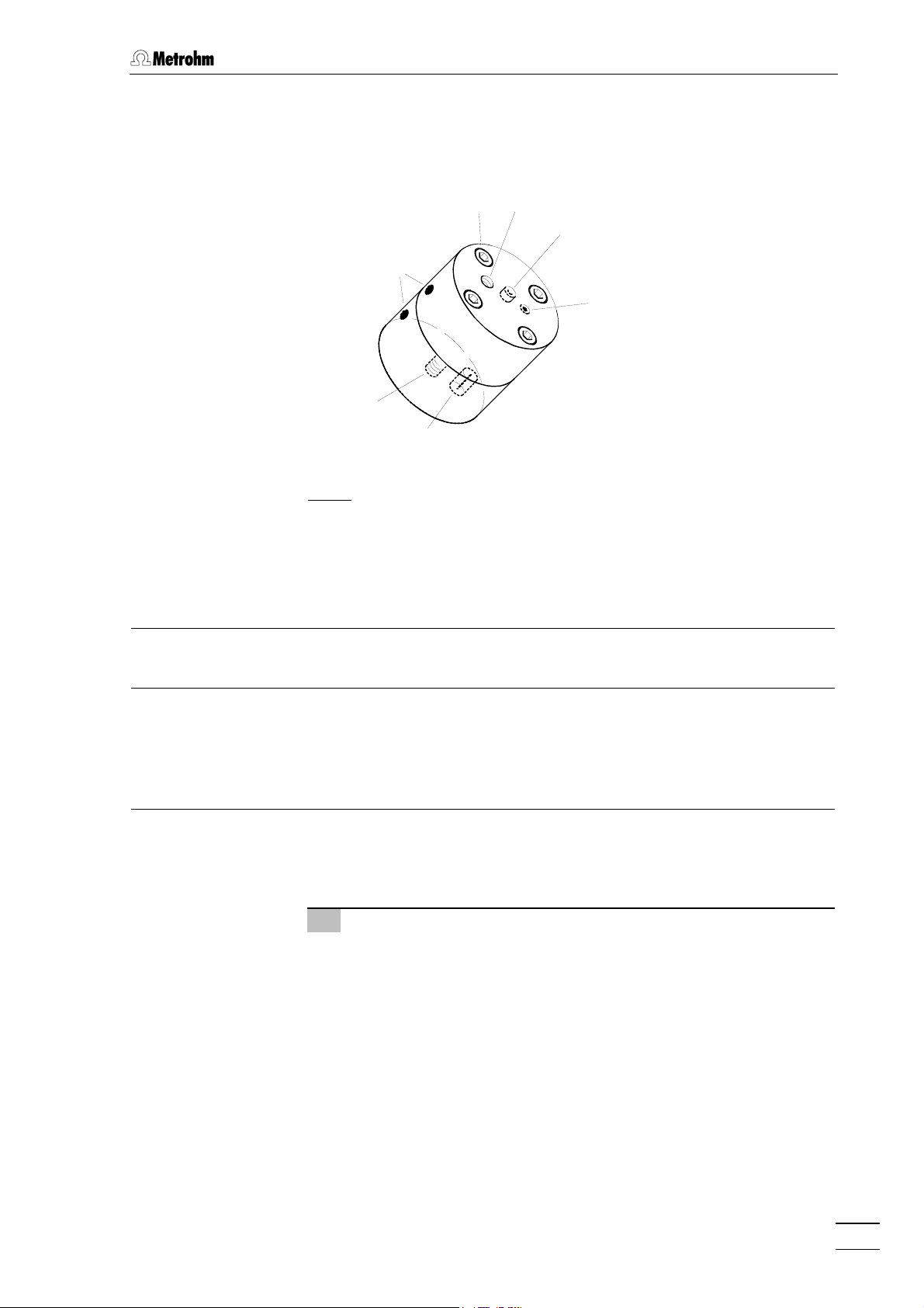
1.2 Parts and controls
1.2 Parts and controls
Bioscan817
Bioscan
1 2 3
: Front of the 817 Bioscan
Fig. 1
Door to interior 3 Feed through for tubing
1
e.g. connection of injection valve and preheating capillary or connection to waste
2 Feed through for tubing
e.g. connection of 709 IC Pump and
pulsation absorber
817 Bioscan
3
Page 12
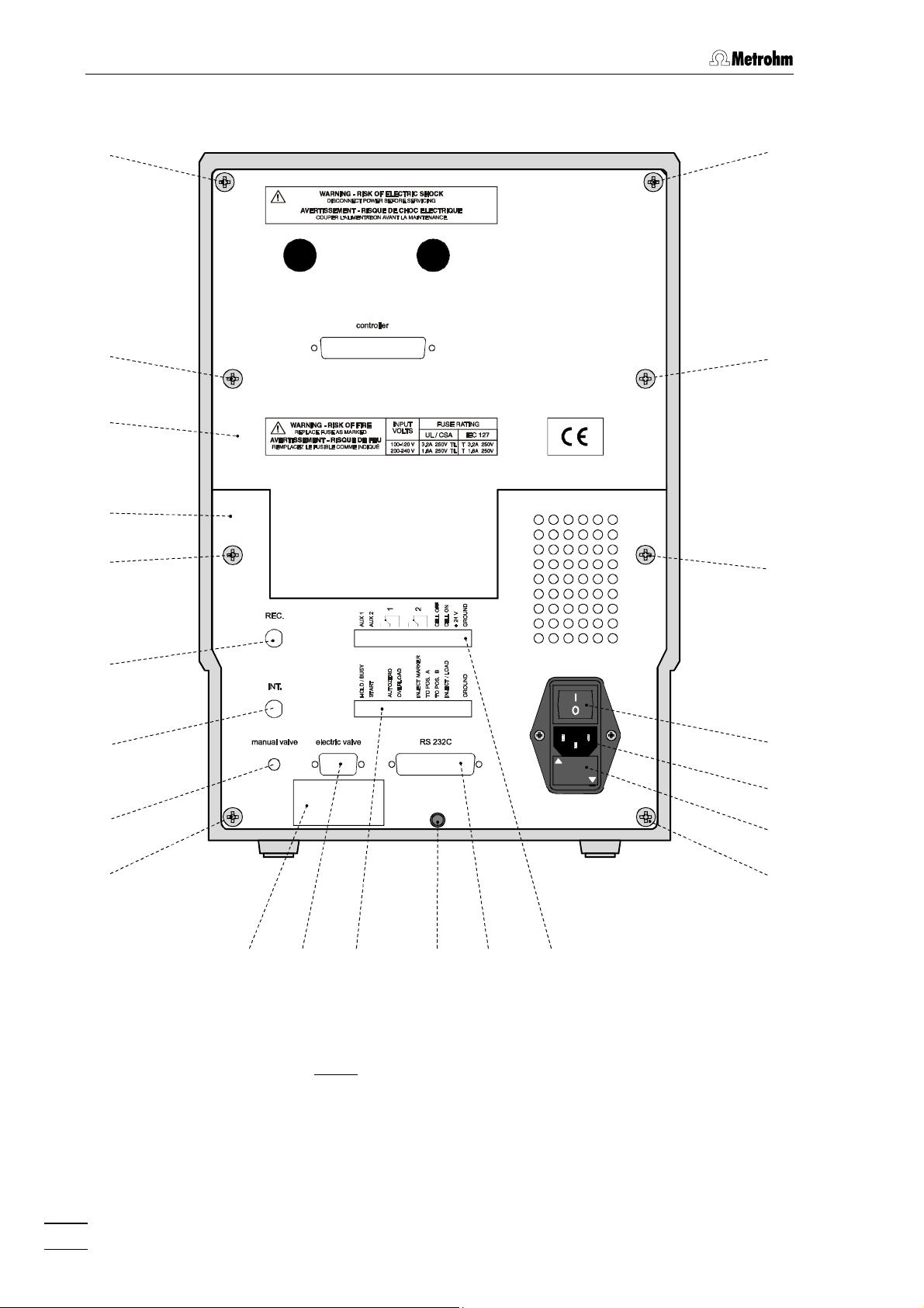
1 Introduction
4
4
4
4
5
6
4
4
7
8
18
17
9
16
4
10
11 14
12 13 15
Fig. 2
: Rear of the 817 Bioscan
4
817 Bioscan
4
Page 13

1.2 Parts and controls
Mounting screw
4
for fastening the rear panels 5 / 6
12 Lower connections for remote lines
(not used with IC Net)
Detachable rear panel
5
access to top part of the inner compartment
6 Detachable rear panel
access to bottom part of the inner
compartment
7 Analog signal (REC.)
AD/DA-converted signal
(not used with IC Net; see chapter 6.1
for details)
8 Analog signal (Int.)
Original signal
(not used with IC Net; see chapter 6.1
for details)
9 Manual valve
(not used with IC Net)
10 Model plate
with technical data serial number
13 Outlet for spilled liquid
for discharge of spilled liquid from the
inner compartment
14 RS232 interface
connection of the PC; see chapter 6.1
for details
15 Upper connections for remote lines
Aux 1, Aux 2 as well as 1 and 2 are
only
used with IC Net
16 Fuse holder
changing the fuses, see section 2.2.1
17 Mains connection plug
mains connection, see section 2.2
18 Mains switch
to switch instrument on and off:
I = ON 0 = OFF
11 Electric valve
(not used with IC Net)
817 Bioscan
5
Page 14
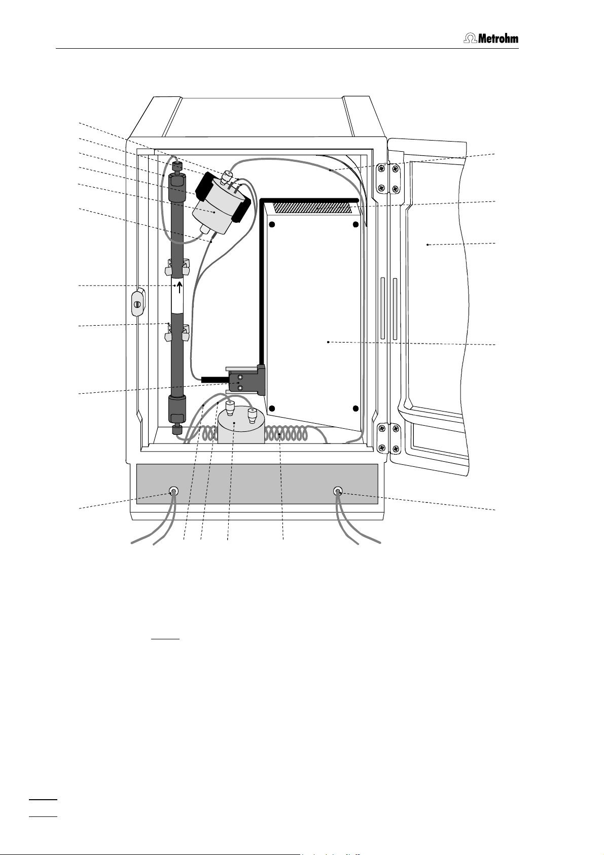
1 Introduction
19
20
21
34
22
23
24
25
26
27
33
1
Metrosep
Carb 1
32
2
29 31
28
: Interior of the 817 Bioscan
Fig. 3
30
(with permanently attached accessories)
3
817 Bioscan
6
Page 15

1.2 Parts and controls
Electrode cable (red)
19
connection for working electrode
27 Connection for elektrode cable
connection '1'
Electrode cable (blue)
20
connection for auxiliary electrode
28 Connection capillary
connection 709 IC Pump – pulsation
absorber
21 Column connection capillary
PEEK capillary
29 Connection capillary
connection pulsation absorber –
injection valve
22 Measuring cell holder 30 Pulsation absorber
6.2620.150
23 Au - Flow cell
6.1254.010
24 Electrode cable (black)
connection for reference electrode
25 IC column
e.g. Metrosep Carb 1 (6.1013.000)
31 Preheating capillary
6.1836.010, length: 3 m
32 Oven
33 Oven heating fan
for carbohydrate analysis
26 Column holder
34 Connection capillary
connection flow cell – waste
817 Bioscan
7
Page 16

1 Introduction
1.3 Information about the Instructions for Use
Please read through these Instructions for Use carefully before you put
the 817 Bioscan into operation. The Instructions for Use contain
information and warnings to which the user must pay attention in order
to assure safe operation of the instruments.
1.3.1 Organization
These Instructions for Use 8.817.1003 for the 817 Bioscan provide a
comprehensive overview of the startup procedure, operation, fault rectification and technical specifications of these instruments. The Instructions for Use are organized as follows:
Section 1 Introduction
General description of instruments, parts and controls
and safety notes
Section 2 Installation
Setting up, mains connection, attachment of accessories, connection to IC system
Section 3 Operation
Detailed description of the operation
Section 4 Basics
Information about the pulsed amperometric detection
Section 5 Notes – Maintenance – Faults
Notes on ion chromatography, maintenance, fault rectification, diagnostic tests, validation
Section 6 Appendix
Technical data, standard equipment, options, warranty,
declarations of conformity, index
To find the required information on the instrument, you will find it an advantage to use either the Table of contents or the Index at the back.
As a supplement to the Instructions for Use, the 8.732.2003 Metrohm
Monograph "Ion chromatography" is also supplied. This provides an
introduction to the theoretical fundamentals and general information on
separating columns and sample pretreatment.
The 8.792.5003 Metrohm Monograph "Practical Ion Chromato-
graphy" is a practical textbook, which provides an illustrative introduction to the basic principles of ion chromatography and also describes
22 experiments covering the whole world of ion chromatography.
IC Application Notes for different applications of Metrohm IC systems
are also supplied.
8
817 Bioscan
Page 17
1.3 Information about the Instructions for Use
1.3.2 Notation and pictograms
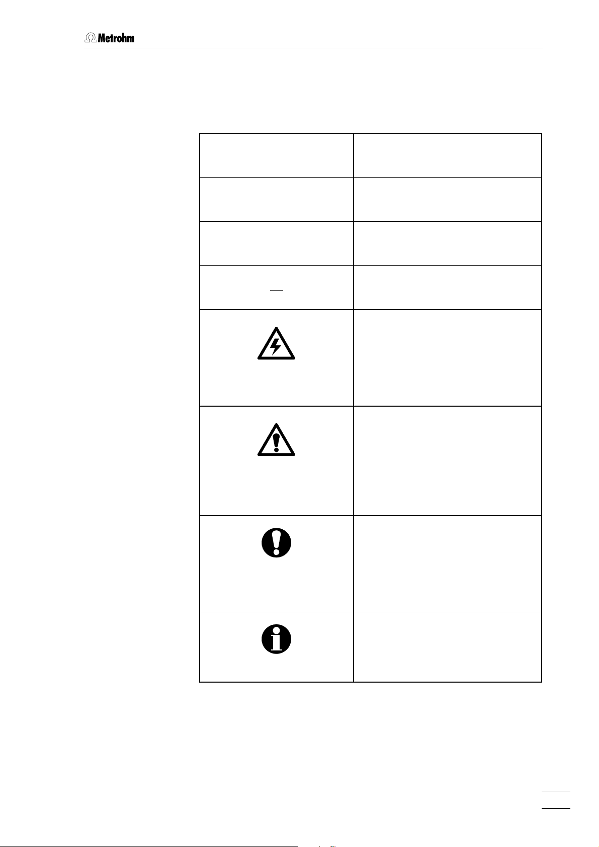
The following notations and pictograms (symbols) are used in these Instructions for Use:
<PARAM> Key
'Range' Parameter or entry value
35 Part or control of 817
22 Part or control of 709
Hazard
This symbol draws attention to a
possible danger to life or of injury if
the associated directions are not
followed correctly.
Warning
This symbol draws attention to
possible damage to instruments or
instrument parts if the associated
directions are not followed correctly.
Caution
This symbol marks important
information. First read the associated directions before you continue.
Comment
This symbol marks additional
information and tips.
817 Bioscan
9
Page 18
1 Introduction
1.4 Safety notes
1.4.1 Electrical safety
While electrical safety in the handling of the 817 Bioscan is assured in
the context of the specifications EN61010-1 / IEC61010-1, the following
points should be noted:
• Mains connection
Setting of the mains voltage, checking the mains fuse and the
mains connection must be effected in accordance with the instruc-
tions in section 2.4.
• Opening the 817 Bioscan
If the 817 Bioscan is connected to the power supply, the instrument
must not be opened (apart from the front door) nor must parts be
removed from it, otherwise there is a danger of coming into contact
with components which are live. Hence, always disconnect the
instrument from all voltage sources before you open it and ensure that
the mains cable is disconnected from mains connection 17 !
• Protection against static charges
Electronic components are sensitive to static charging and can be
destroyed by discharges. Before you touch any of the components
inside the 817 Bioscan, you should earth yourself and any tools you
are using by touching an earthed object (e.g. housing of the instrument or a radiator) to eliminate any static charges which exist.
1.4.2 General precautionary rules
• Handling of solvents
Check all lines of the IC system periodically for possible leaks. Follow
the relevant instructions regarding the handling of flammable and/or
toxic solvents and their disposal.
• Never block drain opening for spilled liquids
On the bottom of the interior directly below the front door there is a
drain opening 1. Spilled liquids can flow directly to the outlet 13 on
the back. Due to safety consideration, take care that these openings
may never be blocked.
10
817 Bioscan
Page 19

2.1 Setting up the instrument
2 Installation
The 817 Bioscan is an electrochemical detector and can be included in
a modular IC system in two different ways:
1) The 817 Bioscan as the only detector in an IC system.
Apart from the 709 IC Pump, you also require an 812 Valve Unit with
one injection valve. In this MIC-8 modular IC system the 817 Bioscan is
intended for the analysis of sugars only.
2) The 817 Bioscan is included in an IC system as the second
detector. An example of this is given in Section 2.5 where an IC system
(MIC-9) is described for the simultaneous determination of sugars and
anions with chemical suppression.
These modular IC system configurations (MIC-1, MIC-2, etc.) are possible instrument combinations that have been properly tested. Under
www.metrohm.com
updated.
you will find further examples; these are continually
Following the general information about the installation of the
instruments, Sections 2.4 and 2.5 describe the two configurations
mentioned above including their control by the «IC Net 2.1» software.
2.1 Setting up the instrument
2.1.1 Packaging
The 817 Bioscan is supplied together with the separately packed
accessories in special packaging containing shock-absorbing foam
linings designed to provide excellent protection. The actual instruments
are packed in an evacuated polyethylene bag to prevent the ingress of
dust. Please store all this special packaging as only it can assure
transport of the instruments free from damage.
2.1.2 Check
After receipt, immediately check whether the shipment is complete and
has arrived without damage (compare with delivery note and list of
accessories in section 6.2). In the case of transport damage, see
instructions in section 6.3.1 "Warranty".
817 Bioscan
11
Page 20
2 Installation
2.1.3 Location
Position the instruments in the laboratory at a location convenient for
operation, free from vibrations and protected against a corrosive atmosphere and contamination by chemicals. The same applies to all
other components of the IC system.
To avoid disturbing temperature influences on the insulated column
compartment, the entire system including pump and eluent reservoir
must be protected against direct sunlight.
2.1.4 Arrangement of the instruments
If the 817 Bioscan is used as a single detector (see chapter 2.4), the
709 IC Pump, 812 Valve Unit and 817 Bioscan are best stacked on top
of one another in this order.
In a two-channel system (see chapter 2.5), the optimum arrangement
(1, 2 or 3 towers) depends on the laboratory space available.
In general, the IC pumps should be set up at the very bottom and the
IC detectors at the very top.
2.2 Mains connection
Follow the instructions below for connecting to the power supply. If
the instrument is operated with a mains voltage set wrongly and/or
wrong mains fuse, there is a danger of fire!
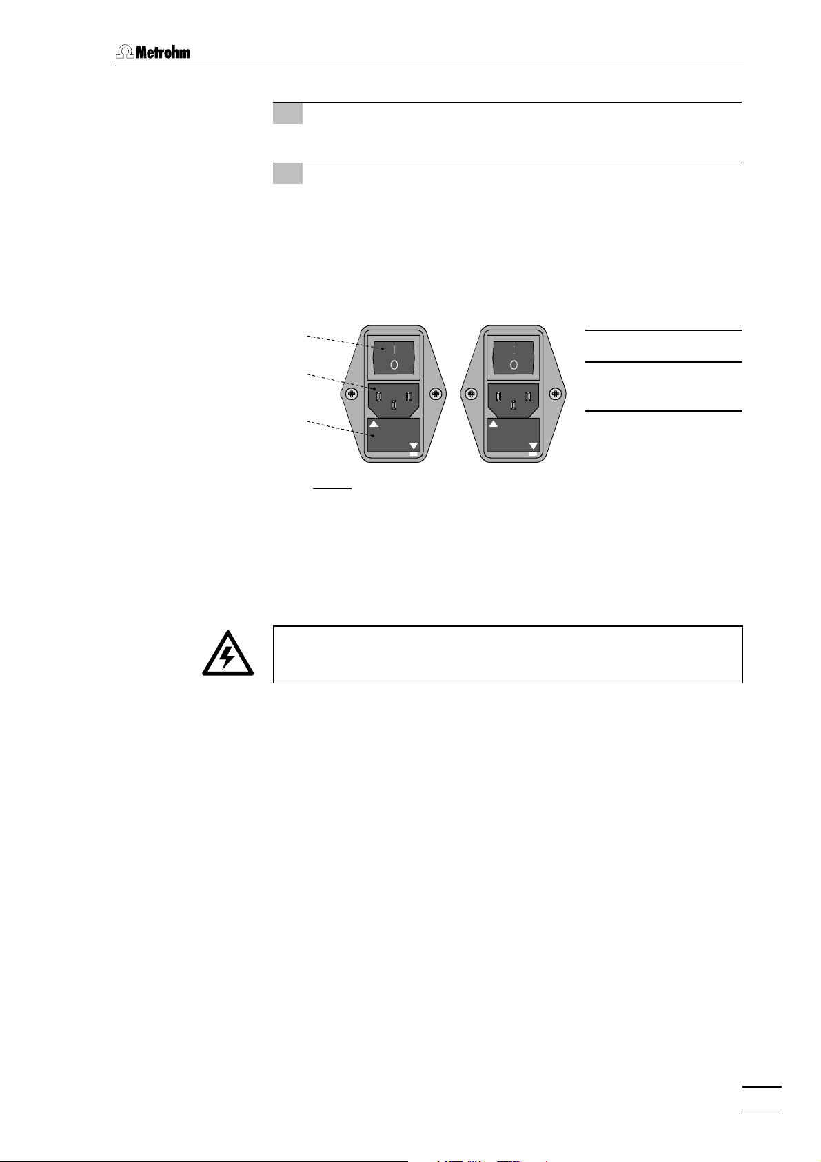
2.2.1 Setting the mains voltage
Before switching on the 817 Bioscan for the first time, check that the
mains voltage set on the instrument (see Fig. 4) matches the local
mains voltage. If this is not
on the instrument as follows:
1 Disconnect mains cable
Disconnect mains cable from mains connection plug 17.
the case, you must reset the mains voltage
2 Remove fuse holder
Using a screwdriver, loosen fuse holder 16 below the mains
connection plug and take out completely.
3 Check and change fuse if necessary
Carefully take the fuses installed for the desired mains voltage
out of fuse holder and check their specifications:
100…120 V 3.15 A (slow-blow) Metrohm No. U.600.0021
220…240 V 1.6 A (slow-blow) Metrohm No. U.600.0018
817 Bioscan
12
Page 21
2.2 Mains connection
V
V
4 Insert fuse
Change fuses if necessary and reinsert in fuse holder.
5 Install fuse holder
Depending on the necessary mains voltage, insert fuse holder in
the 817 Bioscan so that the corresponding mains voltage range
can be read normally and the adjacent white arrow points to the
white bar imprinted below the fuse holder (see Fig. 4).
2.2.2 Fuses
18
17
100 – 120
220 – 240
18 Mains switch
17 Mains connec-
tion plug
16
220 - 240 V
100 - 120 V
100 - 120 V
220 - 240 V
16 Fuse holder
Fig. 4
: Setting the mains voltage
Two fuses 3.15 A/slow-blow for 100…120 V or 1.6 A/slow-blow for
220…240 V are installed in fuse holder 16 of the 817 Bioscan as standard.
Ensure that the instrument is never put into operation with fuses of a
different type as this could cause a fire!
817 Bioscan
For checking or changing fuses, proceed as described in section 2.2.1.
13
Page 22
2 Installation
2.2.3 Mains cable and mains connection
Mains cable
The instrument is supplied with one of three mains cables
• 6.2122.020 with plug SEV 12 (Switzerland, …)
• 6.2122.040 with plug CEE(7), VII (Germany, …)
• 6.2133.070 with plug NEMA 5-15 (USA, …)
which are three-cored and fitted with a plug with an earthing pin. If a different plug has to be fitted, the yellow/green lead (IEC standard) must
be connected to protective earth (protection class 1).
Any break in the earthing inside or outside the instrument can make it
a hazard!
Mains connection
Plug the mains cable into mains connection plug 17 of the 817 Bioscan
(see Fig. 2).
2.2.4 On/off switching of the instruments
The 817 Bioscan is switched on and off using mains switch 18. Do not
switch the IC components on before all cable connections have been
established.
817 Bioscan
14
Page 23
2.3 Capillary connections
2.3 Capillary connections
The capillary connections described below are necessary for operating
the 817 Bioscan in a simple IC system for carbohydrate analysis (MIC-
8). The electronic connections and control by IC Net 2.1 are described
in Section 2.4.
Section 2.5 contains the description of a combination of this IC system
with an IC system for the determination of anions with chemical suppression (MIC-9). The necessary changes to the capillary connections
are described there.
2.3.1 Connection of the 6.5324.000 Bottle rack (option)
The optionally available 6.5324.000 Bottle rack for supply vessels can
be placed on top of the 817 Bioscan. The tubing connections to the 709
IC Pump are described in the corresponding leaflet.
2.3.2 Connecting the pulsation absorber
To protect the column material from any pressure shocks which the injection may cause we recommend the insertion of the 6.2620.150 MF
Pulsation absorber between the high-pressure pump and the injection valve. This is done as follows (see Fig. 3):
1 Connect the pulsation absorber
• Place pulsation absorber 30 on the floor in the interior of the
817 Bioscan.
2 Connection to pump
• Connect the 6.2821.100 PEEK Filter unit described in
Section 2.3.5 of the 8.709.1021 ‘Instructions for Use’ to connection 23
• Lead PEEK capillary 28 or 43
the filter unit outwards through opening 2 of the Bioscan and
attach it to one of the 52 connections on the top side of the
pulsation absorber.
3 Connection to injection valve
• Connect PEEK capillary 29 to the second connection 30 of
the pulsation absorber, lead it out through 2 of the Bioscan
and connection it to the injection valve on the 812 Valve Unit
(connection 17).
The pulsation absorber is filled with isopropanol and must be rinsed
with eluent before a separating column is connected (see Section
2.3.7).
of the 709 Pump by using PEEK capillary 22.
from connection piece 47 of
817 Bioscan
The 6.2620.150 Pulsation absorber can be operated in both directions.
15
Page 24

2 Installation
2.3.3 Connection of the injection valve
Connect all capillaries to the injection valve according to the following
description:
46 45
45
36
21
4447
Fig. 5
: Connections at the injection valve of 2.812.0010 valve unit
Connection for syringe tubing
42
PTFE tubing with coupling
(6.2744.120) and syringe (6.2816.020,
without needle)
43
Connection for aspirating tubing
PTFE tubing for aspirating sample
44 Connection for sample loop
20 µL PEEK sample loop (6.1825.210)
2.3.4 Mounting the column
The IC separating column (e.g. Metrosep Carb 1, 6.1013.000) is first
mounted in the 817 Bioscan as follows (see Fig. 3):
42 43
45 Eluent outlet
Connection to preheating capillary 31
(PEEK, 6.1836.010)
46 Eluent inlet
PEEK capillary connection 29 to
pulsation absorber
47 Connection for sample loop
20 µL PEEK sample loop (6.1825.210)
1 Connect column to the preheating capillary
• Remove the caps from column 25.
• Screw eluent outlet of preheating capillary 31 on to the inlet
end of the column (observe flow direction) .
2 Connect column to flow-through measuring cell
• Screw outlet end of column 25 on to eluent inlet 41 of the
flow-through cell using the 6.2744.130 KELF pressure screw.
3 Fix column
• Fix the column in column holder 26.
817 Bioscan
16
Page 25
2.3 Capillary connections
2.3.5 Connection of the flowcell
The Flowcell (6.1254.010) is a part of the standard equipment of the
817 Bioscan. It is already mounted and ready to use.
37
36
38
35
39
41
40
: Connections at flowcell
Fig. 6
Check marks
35
For correct orientation of the top and
bottom part of the flow-cell
36
Mounting screws (4x)
37 Outlet for eluent
Connection of PEEK capillary by
6.2744.130 KELF pressure screw .
PEEK pressure screws may damage
the threads of the cell.
38 Working electrode connection
for red electrode cable 19
39 Auxiliary electrode connection
for blue electrode cable 20
40 Reference electrode connection
for black electrode cable 24
41 Inlet for eluent
Connection of PEEK capillary by
6.2744.130 KELF pressure screw.
PEEK pressure screws may damage
the threads of the cell.
817 Bioscan
1 Before starting up check all screws 36
• Use the Allen key provided to loosen all four of the 36 screws
by one rotation.
• Then slightly tighten the screws again, e.g. by holding the
Allen key between the thumb and index finger only.
• Finally tighten all four screws by a quarter rotation.
• Always tighten opposing screws, i.e. tighten one screw and
then the opposite screw.
• Avoid overtightening the screws as this could damage the
6.1254.020 Distance piece!
17
Page 26
2 Installation
2 Connect the electrode cable
• The included 6.2156.000 Cable for connecting the measur-
ing cell is attached to connections 38, 39 and 40 of the
measuring cell using the three connectors 19, 20 and 24
(see Fig. 6).
• The other end of the cable is inserted into connection '1' of
the 817 Bioscan 817 with connector 27 (see Fig 3).
3 Connect the column
• Screw column connection capillary 21 of the column on to
eluent inlet 41 of the flow-through measuring cell using the
6.2744.130 Pressure screw.
4 Connect the waste container
• In order to ensure an adequate backpressure, screw a PEEK
capillary (approx. 1 m) on to eluent outlet 37 of the measuring
cell.
• Lead the end through opening 3 into a sufficiently large waste
container and attach it there.
5 Mount the measuring cell
• Attach the flow-through measuring cell to the holder 22 817
Bioscan which is provided for it (see Fig. 3).
• Rotate the holder and the cell so that the cell outlet is located
as high as possible. In this way it is easier for any air bubbles
that may occur to escape from the cell.
Never switch on the flow-through cell when this is
(a) not being rinsed through with a conducting eluent at the
time,
(b) not completely connected up, or
(c) when its outside is moist so that so a short circuit could
occur between the connections of working electrode 38
and auxiliary electrode 39!
2.3.6 Connecting the waste tubing
The 817 Bioscan has an outlet 13 on its rear panel for discharged
liquids to which the waste tubing can be attached. Proceed as follows:
1 Connect the waste tubing
• Attach matching tubing (e.g. Silicone tubing, optional) into
outlet 13 (see Fig. 2).
2 Lead the waste tubing to a drain
• Place the other end of the waste tubing in a drain and attach
it there.
817 Bioscan
18
Page 27

2.3 Capillary connections
2.3.7 Rinsing the tubing
The pulsation absorber is supplied permanently mounted and is filled
with isopropanol. In order to remove this and any air that may be present in the capillaries and the measuring cell all the eluent-carrying tubing or capillary connections must first be installed; the column and the
flow cell must not be connected during the beginning of the process.
Proceed as follows:
1 Deconnect preheating capillary from column
• Deconnect the eluent outlet of preheating capillary 31 from
the column and fix it at a waste bottle.
2 Set injection valve to “Inject”
• Press the <INJECT> key on the 812 Valve unit, which should
not yet be connected to the 817 Bioscan. The green LED in
the key lights up to show that the injection valve is in the “Inject” position.
3 Vent 709 IC Pump before start up
• Proceed according to Section 2.7 of the ‘Instructions for Use’
of the 709 IC Pump.
4 Rinse with dist. H2O
• Immerse the aspiration capillary of the 709 IC Pump in distilled or deionized water.
• Switch on the 709 IC Pump, rinse the IC system for approx.
10 min. and switch off the 709 IC Pump.
5 Rinse with eluent
• Immerse the aspiration capillary of the 709 IC Pump in the
eluent to be used (e.g. 100 mM NaOH).
• Switch on the 709 IC Pump, rinse the IC system for approx.
10 min. and switch off the 709 IC Pump.
6 Connect flowcell and rinse with eluent
• Connect the preheating capillary 31 to flowcell using column
connection capillary 21 and 6.2620.060 Coupling.
• Switch on the 709 IC Pump, rinse the IC system for approx.
10 min. with eluent and switch off the 709 IC Pump.
7 Remove the coupling
• Remove the 6.2620.060 Coupling between column connection capillary 21 and preheating capillary 31.
• Remount the column between column connection capillary
21 and preheating capillary 31 as show in Fig. 3.
2.3.8 Rinsing the column
In order to rinse or precondition the column the connection capillary 21
to flowcell must be unscrewed from the column. Proceed as described
in point 3 and 4 in section 5.2.4.
817 Bioscan
19
Page 28

2 Installation
2.4 System for sugar analysis – MIC-8
The MIC-8 system with manual sample injection is described below. Of
course, you can also install a Metrohm sample changer. This is described in Section 2.5 or in the ‘Instructions for Use’ of the sample
changer.
In order to connect a sample changer and control it completely you
need a further free COM port on your PC. However, we recommend the
use of the 762 IC Interface, to which you can then also connect the 709
IC Pump to be controlled by IC Net 2.1.
2.4.1 Electrical connections
The electrical connections of the MIC-8 system, which consists of the
817 Bioscan, the 812 Valve unit and the 709 IC Pump, are made according to Figure 7:
817
812
709
6.2128.100
6.2125.160
PC
1
AUX 1
AUX 2
123456789
Ground
Fill
2
Inject
: Connecting up a simple modular IC system with the 817
Fig. 7
Bioscan – MIC 8
817 Bioscan
20
Page 29

2.4 System for sugar analysis – MIC-8
2.4.2 Settings in «IC Net 2.1»
1 System
As in this configuration only the 817 Bioscan is to be directly
controlled by IC Net then only this instrument is to be installed as
the detector with the help of the system assistant
wizard
.
2 Method
You should first select the standard method supplied for use
with your particular column (e.g. for Metrosep Carb 1:
CARB1_250.mtw). You can save any alterations under a different
file name.
3 Data source
Select: Cell( 817 BioScan) as the signal source.
4 Save system
Then save the system (e.g. 817_MIC-8.smt).
The following system window should now appear:
New system
5 Connect system and workplace
Under SYSTEM / Control / Connect to workplace connect the
new system with the workplace.
At the same time the symbol will appear in the symbol
bar.
6 Check measuring cell
If the 817 Bioscan is switched on without the flow-through cell
being constantly rinsed by a conducting eluent (e.g. 0.1 M
NaOH) then the measuring cell must not be switched on!
You should now check this in the instrument window of the 817
Bioscan (accessed with a double-click with the mouse on instrument symbol) under
Manual / Cell.
7 Check start mode
Make sure that in this system the 817 Bioscan is standing under
Start with determination under Setup / Start mode.
.
817 Bioscan
21
Page 30

2 Installation
2.4.3 Connecting a sample changer
If the MIC-8 system described above is to be operated with a Metrohm
sample changer then the following connections and settings must be
made:
817
1
AUX 1
AUX 2
1 2 3456789
2
CELL OFF
CELL ON
+ 24 V
GROUND
10 11 12
6.2141.140
766/78 8/813
6.2141.140
812
709
6.2128.100
6.2125.160
PC
Ground
Fill
Inject
Fig. 8: Connecting a simple MIC 8 system including a sample
changer
The IC Sample Processor 766, the IC Filtration Sample Processor
788 or the Compact Autosampler 813 can be used as the sample
changer. In this combination of the MIC-8 system the 817 Bioscan is
operated as the "Master". The start impulse for the instrument methods
to the connected sample changer is transferred via the remote connection (6.2141.140, optional). You can then select any instrument method
at the sample changer that is described as being for control with the PC
as master. Information about this is given in the corresponding ‘Instructions for Use’.
If a second COM port on the PC or a 762 IC Interface is available for an
RS232 connection then the 766 IC Sample Processor or the 788 IC Filtration Sample Processor can be connected up via this connection. In
this way you can generate your own time programs in IC Net 2.1 for
these sample changers. Details are given in the ‘Instructions for Use’ for
the particular instrument.
817 Bioscan
22
Page 31

2.4 System for sugar analysis – MIC-8
Creating the time program
In order to control the 766 IC Sample Processor and the 788 IC Filtration Processor the following program is created in the Bioscan:
In this way shortly after the injection valve has been switched to 'Fill' at
the 812 Valve unit, the first remote line 'AUX 1' (see Fig. 6) will be
switched briefly to 'ON'. This signal will be scanned at the start of the
suitable sample changer programs.
Terminate the program entry by activating the program with
store it in the system with
Save.
Enable and
The control of the 813 Compact Autosampler is carried out similarly.
The only thing to be done here is to set the remote lines to the required
times as described above for each of the three working steps: autosampler start, pump start and pump stop in order for a brief impulse to
be transferred.
In order for the connection Autosampler – 817 Bioscan to function
properly the program must first be started at the sample changer and
then the "Sample queue" in IC Net 2.1.
817 Bioscan
23
Page 32

2 Installation
2.5 System for the analysis of anions and sugars – MIC-9
The combination of an anion system with chemical suppression with the
IC system for sugar analysis is described as an example of a complete
IC system for the simultaneous determination of anions and sugars.
As ideally the two sample loops for the different separation pathways
should be connected by as short a piece of capillary as possible for
sample injection, a 733 IC Separation Center with two injectors
(2.733.0120) is used. This means that the 812 Valve Unit is no longer
required for sample injection for the Bioscan. The MSM Suppressor
Module, which is frequently located in the 733 IC Separation Center, is
then replaced by the 753 IC Suppressor Module which is used instead
of the 752 IC Pump Unit.
2.5.1 Electrical connections
The electrical connection of the system, consisting for example of two
709 IC Pumps, 817 Bioscan, 732 IC Detector, 733 IC Separation Center
(2 injectors), 753 IC Suppressor Module, 762 IC Interface and 766 IC
Sample Processor is made according to the Figure 9:
6.2125 .120
6.2128.130
PC
6.2134.100
6.2128.180
6.2115.070
817
709762
6.2134.090
732
733
709
753
MSM
6.2125.090
6.2141.110
6.2143.210
AB
6.2134.080
Fig. 9
: Connections with a Bioscan 817 as second detector with
a modular IC system – MIC 9
817 Bioscan
24
Page 33

2.5 System for the analysis of anions and sugars – MIC-9
2.5.2 Capillary connections
This section describes the capillary connections required for the combination of the IC system for sugar analysis (MIC-8) with an anion system with chemical suppression (e.g. MIC-2). It is assumed that the capillary connections for the anion system are already known.
Arrange the necessary components as shown in Fig. 9. Please also observe the recommendations about the arrangement of the IC modules
given in Section 2.1.4. The capillary connections for the 817 Bioscan
correspond to a large extent to the connections described in Section
2.3. Only the connection of the injection valve to the 812 Valve Unit is
not necessary. Instead the second injection valve B of the 733 IC Separation Center is connected for injecting the sample for the sugar determination (see below).
For the components for determination of the anions the typical arrangement of the capillaries for such an anion system is assumed to be
present. The necessary alterations concern the injection valve A in the
733 IC Separation Center, which must be connected for injection valve
B so that the two sample loops can be filled simultaneously. In addition
the MSM Suppressor Module connections must be transferred to the
753 IC Suppressor Module if the 752 IC Pump Unit has previously been
used with the MSM Module contained in the 733 IC Separation Center.
The necessary modifications are described below. Injections valves A
and B are designated as follows:
Injection valve A: sample injection for anion determination
Injection valve B: sample injection for sugar determination
All the connections for the two injection valves are shown in Figure 10
on the following page.
1 Connection injection valve A – injection valve B
For simultaneously filling the two sample loops as short as
possible piece of PEEK capillary is attached to sample outlet 48
of injection valve A and sample inlet 55 of injection valve B.
2 Connection pulsation absorber – injection valve B
Connect PEEK capillary 29 to pulsation absorber 52 in the
Bioscan, lead it out through opening 2 or 3 of the Bioscan, and
in through opening 27
or 28 of the 733 IC Separation Center
and connect it to injection valve B (eluent inlet 58).
3 Connection injection valve B – preheating capillary
Connect PEEK capillary at injection valve B (eluent outlet 57),
lead it out through opening 27
or 28 of the 733 IC Separation
Center and in through opening 2 or 3 of the Bioscan and use a
PEEK coupling to connect it to preheating capillary 31.
817 Bioscan
25
Page 34

2 Installation
49 48
A
51 52
Fig. 10
Injection Valve A
48 Sample outlet
PEEK capillary connection to injection
valve B
49 Sample inlet
PEEK capillary connection to sample
processor (18 in Instructions for Use
for 766 IC Sample Processor)
: Connections of injection valves A and B
in the IC Separation Center (2.733.0120)
- Anions -
55 54
12
63
54
5350
57 58
54 Sample outlet
PTFE tubing connection to waste
55 Sample inlet
PEEK capillary connection to injection
valve A
12
63
B
54
5956
Injection Valve B
- Carbohydrates -
50 Connection for sample loop
PEEK sample loop for anion analysis
51 Eluent outlet
PEEK capillary connection to anion
separation column
52 Eluent inlet
PEEK capillary connection, e.g. to
pulsation absorber for anion eluent
53 Connection for sample loop
PEEK sample loop for anion analysis
56 Connection for sample loop
20 µL PEEK sample loop (6.1825.210)
57 Eluent outlet
Connection of preheating capillary 31
(PEEK, 6.1836.010)
58 Eluent inlet
PEEL capillary connection 29 to
pulsation absorber
59 Connection for sample loop
20 µL PEEK sample loop (6.1825.210)
817 Bioscan
26
Page 35

2.5 System for the analysis of anions and sugars – MIC-9
2.5.3 Configuration in IC Net 2.1
The complete IC system is installed in IC Net using the New system
wizard
:
1 762 IC Interface
2 732 IC Detector
3 817 Bioscan
4 709 IC Pump
817 Bioscan
27
Page 36

2 Installation
5 709 IC Pump
6 766 IC Sample Processor
7 733 IC Separation Center
8 753 Suppressor Module
817 Bioscan
28
Page 37

2.5 System for the analysis of anions and sugars – MIC-9
9 Second data recorder
10 Anion method and data source
11 System overview
12 Final settings
In the system window of the 753 Suppressor Module the option
Start pump with hardware should be activated under Manual.
817 Bioscan
29
Page 38

2 Installation
13 Bioscan method and data source
The Bioscan method and corresponding data source must be
selected in the
Setup menu which can be accessed by a right-
hand mouse click on the second data recorder symbol.
14 Connect system with workplace
Under SYSTEM / Control / Connect to workplace connect the
new system with the workplace.
At the same time the symbol
appears in the symbol bar.
15 Check measuring cell
If the 817 Bioscan is switched on without the flow-through cell
being constantly rinsed by a conducting eluent (e.g. 0.1 M
NaOH) then the measuring cell must not be switched on!
You should now check this in the instrument window of the 817
Bioscan (accessed with a double-click with the mouse on instrument symbol) under
Manual / Cell.
16 Check connections
You can now check the electronic connections to all modules.
This is done by double-clicking with the left-hand mouse key on
each instrument symbol. If the connection is functioning properly
then the current status of the instrument parameters will be
shown.
Remarks
• The event-line for the suppressor of the 753 Suppressor Module
is only set up as a "dummy connection" (Step 8). The real command for switching the suppressor further is made by the 766
Sample Changer via a remote line.
• For the installation described above the option
Stacked recorder icons
Options / Global preferences. This is why only a symbol for the
must be activated in IC Net 2.1 under
System face /
data recorder is visible in the system overview. With a right-hand
mouse click and the offered
Setup option the setting possibili-
ties described for both recorders man (Step 10 and Step 13)
can be accessed.
817 Bioscan
30
Page 39

2.5 System for the analysis of anions and sugars – MIC-9
Creating the time program
1. Input of the program for the 766 IC Sample Processor (Master):
001 Ctrl INIT
002 Move sample
003 Lift work
004 Ctrl ZERO 1
005 Ctrl FILL A 1
006 Ctrl STEP MSM 753
007 Ctrl FILL B/Step 1
008 Pump 120 s
009 Ctrl INJECT A 1
010 Ctrl INJECT B 1
− Initialize remote interface
− Move needle to sample position
− Move lift with needle to working height
− Trigger Autozero on 732 IC Detector
− Switch injection valve A on 733 to "Fill"
− Switch on 753 Suppressor-Module
− Switch injection valve B on 733 to "Fill"
− Fill sample loops A + B with sample for 120 s
− Switch injection valve A on 733 to "Inject"
− Switch injection valve B on 733 to "Inject"
1. Terminate the program entry by activating the program with
and store it in the system with
Save.
Enable
2. Finally check that in the IC system the 766 Sample Processor is entered under
Start with inject under Setup / Start mode.
Remarks
If only one of the detection pathways is to be used in this IC system
then the modules which are not required can be removed from the system (remove recorder and instrument symbols with the right-hand
mouse key and
However, please note that in this instrument configuration the recording
of the Bioscan data nevertheless begins only when the injection valve A
on the 733 IC Separation Center is switched from
is only a corresponding connection to the 762 IC Interface from this
valve (see Fig. 9). This means that even if only sugar analysis is to be
carried out, the 733 IC Separation Center and the 732 IC Detector must
still form part of the system described above. The program described
above for the 766 IC Sample Processor must then remain unchanged.
Unlink) and save the system under a new name.
Fill to Inject, as there
817 Bioscan
31
Page 40

2 Installation
2.6 Preparing the 817 Bioscan for the analysis
This section describes the necessary steps for preparing the 817 Bioscan to carry out an analysis. A more detailed description of the operation of the 817 Bioscan using IC Net 2.1 can be found in Section 3 and
in the ‘Instructions for Use’ of the 8.110.8221 Metrodata IC Net 2.1
software.
2.6.1 System switch-on
1 Mains on
Start up the individual instruments and the IC Net program in the
following sequence:
1. Computer
2. IC instruments
3. IC Net 2.1
2 Check measuring cell
For safety reasons check the status of the measuring cell in the
instrument window of the Bioscan (accessed by a double-click
with the mouse on the instrument symbol) under
Manual / Cell.
If the 817 Bioscan is switched on without the flow-through
measuring cell being constantly rinsed through a conducting
eluent (e.g. 0.1 M NaOH) or correctly connected up then the
measuring cell must not be switched on!
3 Check the external control of the 709 IC Pump
Depending on the control of the 709 IC Pump (MIC-8: manual;
combination with 762 IC Interface: external) the setting of the
external control of the IC Pump should be checked with key 8
<EXT.>.
2.6.2 Start pump
1 Column/ Eluent
With the Metrosep Carb 1 (6.1013.000) column use 0.1 M NaOH
(quality) as the eluent for sugar analysis. This should be made
up and degassed freshly every day; it should at least be degassed before use each day.
2 Flow rates / Pressure
The Metrosep Carb 1 column should not be subjected to large
variations in pressure. For this reason each time that the eluent
is used it should be pumped for a period of 10 minutes both
before and after use at 0.3 mL/min. For normal operation a flow
rate of1.0 mL/min is used.
Set a maximum pressure P
0.1 M NaOH this should establish a pressure of approx. 9 - 10
MPa with the Metrosep Carb 1.
817 Bioscan
32
of 15 MPa. At 1 mL/min and with
max
Page 41

2.6 Preparing the 817 Bioscan for the analysis
2.6.3 Set operating mode
1 Manual control of the 817Bioscan
• In the instrument window of the Bioscan (double-click with the
mouse on the instrument symbol) select
Mode: Pulse for
pulse amperometric detection.
• The cell must remain deactivated for as long no eluent flows
through the flow-through measuring cell.
• The oven is set to e.g. 32 °C. In general this temperature
should be at least 10 °C higher than the ambient room temperature.
817 Bioscan
33
Page 42

2 Installation
2 Parameters for the pulse mode
• Set these method parameters for the pulse mode. Please
note that this menu can only be accessed when the option
Pulse has been selected for Mode under Manual (see above).
• Finally transfer the current parameters to Bioscan with <
and use
System / Save to save them in the system file (*.smt).
The IC system with the 817 Bioscan is now ready for use.
Set>
817 Bioscan
34
Page 43

3.1 Handling the 817 Bioscan
3 Operation
3.1 Handling the 817 Bioscan
General
Amperometric detection takes place with a flowing current and therefore with a chemical conversion of the analyte. The course of a chemical reaction depends directly on various physical parameters, among
other things. In order to obtain optimum measuring conditions (e.g.
stable baseline or reproducible signals) it is necessary to take the following points into consideration. Further information can be found in
Section 4.2.
Constant temperature
The 817 Bioscan allows the interior of the instrument to be kept at a
constant temperature of up to max. 60°C. The lower limit is the ambient
temperature plus 10 °C. Under IC Net you should activate the appropriate oven-operating mode in the 817 method parameters and define the
temperature (see Section 3.2.2)
Constant pH
The characteristic current/potential curves of all electrochemically reactive substances depend very strongly on the pH of the pH eluent used.
This means that you should prepare the eluent very carefully and check
its pH at regular intervals.
Pulsation-free eluent flow
Changes to the eluent flow should be avoided as far as is possible. The
6.2620.150 Pulsation Absorber is available for this purpose; it is
mounted between the 709 IC Pump and the injection valve as described in Section 2.3.2.
Never make dry measurements
The flow-through measuring cell must not be switched on if it is not
being rinsed constantly by the eluent or if the measuring cell is not
connected up properly!
817 Bioscan
35
Page 44

3 Operation
3.2 Operation using «IC Net 2.1»
3.2.1 817 Bioscan icon
The 817 icon is available in the system window if an 817 Bio-
scan
has been installed with the New system wizard or by us-
ing the Setup/New devices/Install new device option of the
SYSTEM window (see section 2.4.2).
If the system is connected and the 817 icon is clicked with
the right-hand mouse button then the following menu appears:
Open Opens the 817 Bioscan window for parameter set-
tings (this window can also be opened by double-clicking the icon).
Unlink Deletes the 817 icon from the system.
817 Bioscan
36
Page 45

3.2 Operation using «IC Net 2.1»
3.2.2 817 Bioscan window
817 icon / Open
The 817 Bioscan window for parameter settings is opened by
selecting this menu option with the right-hand mouse button
or by double-clicking the 817 icon in the SYSTEM window. It
consists of the four tabs Manual, Method parameters, Program,
and Links.
Manual
The Manual tab of the 817 Bioscan window is only available
for a connected system.
817 Bioscan
Mode Selection of detector mode:
DC In the DC mode a constant potential is ap-
plied; the analytes are oxidized or reduced
in accordance with their electrochemical
properties.
Pulse The Pulse mode works with three different
potentials that are applied cyclically. This
frees the electrode surface from any adhering reaction products during each sweep
and an activated surface is produced for
the next measurement.
Scan The Scan mode allows potential/current
curves to be recorded.
37
Page 46

3 Operation
Cell Manual control of amperometric detector
cell:
<On> Switches on detector cell.
<Off> Switches off detector cell.
Attention
Switch on the detector cell only if a conducting eluent is being pumped through it continuously!
Oven Manual control of column oven (heater):
<On> Switches on oven.
<Off> Switches off oven.
Temperature Temperature of column oven.
Range:
15 ... 60 °C (> room temp. + 10 °C)
Control Manual setting of 4 remote lines.
<Set> Sets remote lines to selected states.
Aux1, Aux2, Cont1, Cont2
Setting of 4 remote lines.
Selection:
Valve Manual switching of the injection valve,
0, 1, *
e.g. at the 812 Valve Unit:
<Fill> Switches injection valve to "Fill" position
(control line Cont1 is set to 0).
<Inject> Switches injection valve to "Inject" position
(control line Cont1 is set to 1).
Analog output
Manual setting of the analog output signal
to zero. For RS232 data the full-scale range
(see next page) is shifted until the signal is
located in the center of this range again (s.
also Chapter 6.1).
<Zero> Triggers the autozero function.
Actual
Display of actual values.
Mode Display of current detector mode.
Cell Display of current cell state.
Oven
Control
817 Bioscan
38
Display of current oven state.
Display of current control line settings.
Page 47

3.2 Operation using «IC Net 2.1»
Method parameters
DC mode
The DC mode subtab of the Method parameters tab on the 817
Bioscan
window is used to set the parameters for the DC
mode. This window is only available if Mode has been set to
DC on the Manual tab.
Method data
Cell potential Electric potential applied to the amperomet-
ric detector cell in V
Range:
Oven Switches column oven on/off and sets op-
-2 ... +2 V.
erating temperature.
Range: 15 ... 60 °C (> room temp. + 10 °C)
Range Selection of measuring range:
pA 10 ... 5000 pA.
nA 0.1 ... 50 nA.
µA 0.01 ... 5 µA.
Full scale The full-scale range (operating range) sets
the desired sensitivity for the analog output.
The possible values of the full-scale range
depend on the preset measuring Range. For
RS232 data (IC Net 2.1), always the maximum settings should be used.
817 Bioscan
39
Page 48

3 Operation
Filter Electronic damping of the analog output
(REC) and RS232 signal.
Selection: 0.1, 0.2, 0.5, 1, 2, 5 s
Offset
Offset of the zero point.
Selection: -50 ... +50 % (in steps of 10 %)
Actual
Cell potential Display of current cell potential in V
Oven Display of current oven state.
Range Display of current measuring range.
Full scale Display of current full-scale range.
Filter Display of current damping constant.
Offset Display of current offset.
<Set> Sends current parameters immediately to
the 817 Bioscan. Parameters are not stored
in the system file (*.smt) as long as the file
is not saved.
817 Bioscan
40
Page 49

3.2 Operation using «IC Net 2.1»
Pulse mode
The Pulse mode subtab of the Method parameters tab on the
817 Bioscan window is used to set the parameters for the
pulse mode. This window is only available if Mode has been
set to Pulse on the Manual tab.
Method data
Cell Definition of three different working poten-
tials that are applied to the amperometric
detector cell cyclically. The set potentials
are graphically displayed if the Method option is enabled above the graphic window.
E1, E2, E3 Potentials.
Range: -2 ... +2 V.
t1, t2, t3 Time duration to apply the potentials.
Range: 0.01 ... 2 s
Sample time
Measuring time at the end of working po-
tential E1.
Selection: 20, 40, 60, 80, 100 ms
Oven Switches column oven on/off and sets op-
erating temperature.
Range: 15 ... 60 °C (> room temp. + 10 °C)
Range Selection of measuring range:
pA 10 ... 5000 pA.
nA 0.1 ... 50 nA.
µA 0.01 ... 5 µA.
817 Bioscan
In the Pulse mode, always the µA range
should be selected.
41
Page 50

3 Operation
Full scale The full-scale range (operating range) sets
the desired sensitivity for the analog output.
The possible values of the full-scale range
depend on the preset measuring
Range. For
RS232 data (IC Net 2.1), always the maximum settings should be used.
Offset Offset of the zero point.
Selection: -50 ... +50 % (in steps of 10 %)
Actual
E1, E2, E3 Display of current potentials in V.
t1, t2, t3 Display of current time durations for poten-
tials in s.
Sample time Display of current sample time in ms.
Oven Display of current oven state.
Range Display of current measuring range.
Full scale Display of current full-scale range.
Offset Display of current offset.
Cycle potentials Graphical display of cycle potentials.
Method Display of potentials set in the Method data
frame.
Actual Display of current potentials.
<Set> Sends current parameters immediately to
the 817 Bioscan. Parameters are not stored
in the system file (*.smt) as long as the file
is not saved.
817 Bioscan
42
Page 51

3.2 Operation using «IC Net 2.1»
Scan mode Parameters
The Scan mode subtab of the Method parameters tab on the
817 Bioscan window is used for parameter setting and curve
display for the scan mode. This window is only available if
Mode has been set to Scan on the Manual tab.
Method data
Cell potential Definition of start and end potential for a
user-defined potential sweep that is applied
to the amperometric detector cell.
E1 Start potential for sweep.
Range: -2 ... +2 V.
E2 End potential for sweep.
Range: -2 ... +2 V.
Scan cycle Definition of scan cycle:
full double scan E1 ... E2 ... E1
half single scan E1 ... E2
Selection: full, half
Scan rate Definition of scan rate in mV/s.
Selection: 1, 2, 5, 10, 20, 50 mV/s
Oven Switches column oven on/off and sets op-
erating temperature.
Range: 15 ... 60 °C (> room temp. + 10 °C)
Range Selection of measuring range:
pA 10 ... 5000 pA.
nA 0.1 ... 50 nA.
µA 0.01 ... 5 µA.
817 Bioscan
43
Page 52

3 Operation
Full scale The full-scale range (operating range) sets
the desired sensitivity for the analog output.
The possible values of the full-scale range
depend on the preset measuring
Range. For
RS232 data (IC Net 2.1), always the maximum settings should be used.
Offset Offset of the zero point.
Selection: -50 ... +50 % (in steps of 10 %)
Actual
E1, E2 Display of current start and end potentials
in V.
Scan cycle Display of current scan cycle mode.
Scan rate Display of current scan rate in mV/s.
Oven Display of current oven state.
Range Display of current measuring range.
Full scale Display of current full-scale range.
Offset Display of current offset.
<Set> Sends current parameters immediately to
Scan mode Operations
the 817 Bioscan. Parameters are not stored
in the system file (*.smt) as long as the file
is not saved.
817 Bioscan
44
Page 53

3.2 Operation using «IC Net 2.1»
Caption Possibility of entering a title that is written
at the head of the scan mode graphics
window.
Program
<Add date & time>
The current date and time are added to
the title defined in the Caption field.
State Display of current state.
<Start> Starts scan mode sweep.
<Stop> Stops scan mode sweep.
<Copy to clipboard> Copies the content of the scan mode
graphics window to the clipboard.
On the Program subpage, program steps including time,
program instruction and parameter can be entered.
First column Time at which program instruction is
applied.
Entry range: 0.0 ... 999.9 min
If no time is entered, the program instruction is applied to-
gether with the last instruction with time
entry.
Second column Program instruction (see below).
Third column Parameter for program instruction (see
below).
ENABLED Enable program start (a disabled pro-
gram is not started).
<Add> Add new program instruction.
<Delete> Delete selected program instruction.
<Verify> Test the time program (error messages
are displayed if program is wrong).
817 Bioscan
45
Page 54

3 Operation
List of program instructions
The following program instructions can be added to the time
program on the
Program subpage:
Instruction Parameter entry Meaning
Mode DC, Pulse, Scan
Cell On, Off Switch cell on/off.
Outputs 0, 1, * Set remote lines Aux1, Aux2, Cont1
Select detector mode.
and Cont2 to desired values. For entry
of the first value, enter
1, 0 or *. For
entry of the other values, move the
cursor in front of the value to be
changed and enter
Range pA: 10 pA – 5 nA
nA: 0.1 nA – 50 nA
µA: 10 nA – 5 µA
Offset -50, -40, -30,…50 % Set offset for measuring signal.
Valve Fill, Inject Switch connected injection valve.
Oven off, 15 ... 60 °C Set column oven temperature.
Autozero Trigger analog output signal auto
Set measuring range.
1, 0 or *.
zero.
DC_E -2 ... +2 V Set measuring potential (DC).
Filter 0.1, 0.2, 0.5 ... 5 s Set electronic damping for the
analog output signal.
Scan_E1 -2 ... +2 V Set sweep start potential E1.
Scan_E2 -2 ... +2 V Set sweep end potential E2.
Scan_Cycle half, full Select scan cycle type.
Scan_Rate 1, 2, 5, … 50 mV/s Set scan rate.
Links
The Links tab of the 817 Bioscan is used for COM port selection and settings (details see Section 5.2.4 in the Software
Manual for IC Net 2.1).
817 Bioscan
46
Page 55

4.1 Introduction
4 Basic principles
4.1 Introduction
The 817 Bioscan can be operated as an amperometric detector in
three different working modes:
• DC mode A constant potential is applied to the working elec-
trode. The analyte substances are oxidized or reduced according to their electrochemical properties.
The current that is produced is measured.
• Scan mode Current-potential curves are recorded in order to de-
termine the optimum parameters for pulsed amperometric detection. This is done by passing a solution that contains only the substance of interest
through the measuring cell and recording a currentpotential curve.
• Pulse mode Three different potentials are applied cyclically to
the working electrode. This frees the electrode surface from any adhering reaction products and reactivates it for the next measurement. As this is the
operating mode that is primarily used with the 817
Bioscan for carbohydrate analysis it is described in
detail in Section 4.2.
817 Bioscan
47
Page 56

4 Basic principles
4.2 Measuring conditions
Amperometric detection takes place with a flowing current and therefore with a chemical conversion of the analyte. The course of a chemical reaction depends directly on various physical parameters, among
other things. In order to obtain optimum measuring conditions (e.g.
stable baseline or reproducible signals) it is necessary to take the following points into consideration:
• Temperature The reactions occurring at the working electrode
(oxidation and reduction) are influenced by the temperature. However, this applies not only to the conversion of the analyte, but also for interfering reactions that produce the background current. This is
the reason why a constant temperature is a necessary precondition for obtaining a stable baseline
and reproducible signals. For the determination of
carbohydrates, lower temperatures (30 °C – 35 °C)
are suitable. Furthermore, the flowcell should not be
operated above 45 °C over a longer time period.
• pH Just like the temperature, the pH of the eluent also
has a direct influence on the electrochemical reactions at the working electrode. pH alterations cause
a displacement of the characteristic current/potential curves (voltammograms). Possible results are
the reduction of the signal intensity and lower signal/noise ratios. In order to ensure that a stable
baseline and reproducible measuring conditions are
obtained care should be taken that the pH of the
eluent is correct.
• Pulsation Electrochemical reactions at the electrode surfaces
depend on the transport of the reacting substances
to the electrode. This is why a constant eluent flow
is crucial, both for a stable baseline and also for reproducible signals. This is why pulsation-free eluent
supply must be ensured. You should use the pulsation absorber provided (see Section 2.3.2).
817 Bioscan
48
Page 57

4.3 Pulsed amperometric detection
4.3 Pulsed amperometric detection
During an amperometric determination the reaction products formed on
the working electrode can alter its surface properties by adsorption. In
pulsed amperometric detection (PAD) it is possible to apply further potentials cyclically in addition to the detection potential in order to ensure
a constant electrode surface. In this way the electrode surface is renewed after each current measurement and remains in this activated
condition.
The exact potential steps are shown in Fig. 11 as a function of time.
Fig. 11: Potentials applied during pulsed amperometric detection (PAD)
The working potential E1 is applied during the time t1 with the signal
being measured in ts. The high positive potential E2 causes the oxidative removement of reaction products from the electrode surface, which
is reduced to a pure Au-surface during t3.
4.3.1 Optimization of the PAD parameters
When adapting the method parameters the preset parameters should
initially be used. Descriptions of various applications are available from
Metrohm AG in the form of Application Works and Application Notes.
These can be obtained from your local Metrohm agency or on the Internet under www.metrohm.com
The potential profile shown in Fig. 11 must always be matched to the
analyte under investigation. 7 parameters must be taken into account:
potentials E1, E2 and E3, time intervals t1, t2 and t3 and the measuring
time ts. Some basic conditions are preset; this makes configuration
easier. These are described below.
.
2.0 1.0
817 Bioscan
49
Page 58

4 Basic principles
Measuring interval (E1, t1 and ts)
The measuring potential depends on the substance being investigated.
If no data is available in the literature that can initially be used for optimization then you can determine these parameters yourself. For this
reason Bioscan has the scan mode available, among other things. Recording the corresponding voltammograms is described in Section 4.4.
As each change in potential can cause a higher charging current to occur at the working electrode, the current measurement itself is only
started when the signal has stabilized itself to a large extent. This time
is defined as t1 – ts (see Fig. 11). It influences the level of the background current and should therefore be selected so that it is not too
small. In practice a time of 0.1 to 0.4 s is frequently used.
The measuring interval ts can be set to 20, 40, 60, 80 or 100 ms. These
values correspond to multiples of 50 Hertz. In this way possible interference from the mains current supply can be avoided.
Regeneration interval (E2, E3, t2 and t3)
The potentials E2 and E3 which are required for the regeneration of the
electrode surface are primarily determined by the material of the working electrode.
With the gold electrode used the oxide layer is already formed at E2 >
+200 mV (Ag/AgCl) under alkaline conditions. Higher potentials accelerate oxide formation, therefore in practice E2 = +750 mV and t2 = 0.2
s are often selected.
For example, –800 mV at 0.2 s or –150 mV at 0.4 s can be selected for
E3 and t3.
Measuring frequency
In pulsed amperometric detection the total of the three individual intervals (t1 + t2 + t3) represents the duration of one measuring cycle. The
reciprocal of this cycle duration (in seconds) gives the pulse fre-
quency. Please note that the measured value is outputted from the detector at this pulse frequency. The sampling frequency which otherwise has to be set under IC Net for data acquisition (
M
ethod setup / Measure / Sampling rate and Frequency divisor) is
automatically adapted accordingly.
IC NET / Method /
817 Bioscan
50
Page 59

4.4 Optimization of the measuring potential
4.4 Optimization of the measuring potential
An optimization of the measuring potential for amperometric detection
may bring benefits in the following situations:
a) The sensitivity of the detection of the analyte is to be increased
against the background signal.
b) The selectivity of the detection is negatively affected by the analyte
peak overlapping with a second substance peak that has not been
optimally separated by chromatography.
If there are no suitable literature data available, this requires the recording of a voltammogram. This is a curve showing the relationship
between the given potential and the measured current. It is characteristic for individual chemical substances or even whole classes of substances.
There are two different types of voltammograms, each of which is suitable for solving a different problem: a hydrodynamic voltammogram
and a scan voltammogram.
Fig. 12
A hydrodynamic voltammogram is made of several chromatograms
recorded in the DC mode. This involves recording a chromatogram of
the substance under investigation, dissolved in eluent, at a constant potential. The potential is now varied several times and the process is repeated. Finally the height of the current peak obtained is evaluated and
plotted against the particular potential. Fig. 12 shows a schematic example of such a hydrodynamic voltammogram:
I
: Example of a hydrodynamic voltammogram of a substance (A)
with the additional presentation of the measured values for the
pure eluent (B)
817 Bioscan
This method is advantageous if the analyte is not present in a pure
form. It also provides more realistic information about the signal/noise
ratio and the selectivity towards overlapping peaks.
51
Page 60

4 Basic principles
The scan voltammogram is recorded in the scan mode. The measuring potential is varied backwards and forwards between two given limits
while the analyte is passed through the measuring cell. The actual current is then measured for each potential.
The substance under investigation can be dissolved in the IC eluent
used (e.g. 10 ppm Sucrose in 0.1 M NaOH) and a larger amount (e.g.
100 mL) pumped through the flow cell without a separation column
connected. If you work on trace concentrations of your analyte and
worry about contamination of your IC system you can still inject the
substance into the eluent using a large sample loop (> 500 µL). The
eluent should then be pumped at a very low flow rate (e.g. 0.05
mL/min).
In principal, same conditions should be used as they are needed for the
chromatographic separation (e.g. temperature, pH, eluent etc.).
Fig. 13 shows a schematic example of a scan:
Fig. 13
: Example of a scan of a substance (A) with the additional repre-
sentation of the scan of the pure eluent (B)
When using metal electrodes as the working electrode, such as the
gold electrode used here, the reaction products formed by the amperometric detection during the scan method can form an interfering
layer on the electrode surface and influence the results. For this reason
a hydrodynamic voltammogram is to be preferred in such cases.
The following table summarizes the requirements for and the advantages and disadvantages of these two methods.
817 Bioscan
52
Page 61

4.4 Optimization of the measuring potential
Situation
Requirement
Advantages
Disadvantages
Hydrodynamic
voltammogram
• Selectivity for an inadequate
IC-separation is to be improved
• Substance can be investigated in the mixture
• IC parameters must be
known
• "Chromatographic" conditions, i.e. a direct check of
selectivity and sensitivity is
possible
• Several substances can be
investigated at the same time
• More time required for a
single substance
Scan
voltammogram
• Sensitivity of a substance
peak is to be increased
• Substance must be present in
a pure form
• Less time needed for single
substances
• Possible formation of an oxide
layer on the working electrode
The final aim is to select a suitable potential for use as the measuring
potential for pulsed amperometric detection. This means that usually a
compromise has to be found between the highest possible sensitivity,
selectivity and reproducibility:
Higher potentials can increase the sensitivity; however, more substances can also be determined and this reduces the selectivity. In order to achieve high reproducibility, a potential from a flatter segment
near to the maximum of the analyte voltammogram should be selected.
In the example shown in Fig. 12, E
was a potential determined in this
1
way.
During the determination of the optimum measuring potential the
constancy of the parameters pH and temperature as well as the
pulsation-free eluent supply are important (see Section 4.2).
817 Bioscan
53
Page 62

4 Basic principles
817 Bioscan
54
Page 63

5.1 Practical notes on ion chromatography
5 Notes – Maintenance – Faults
5.1 Practical notes on ion chromatography
5.1.1 Separating columns
Separation efficiency
The attainable quality of analyses with an IC system depends to a large
extent on the separation efficiency of the column used. When purchasing an IC column you should ensure that the separation efficiency suffices for the analysis problems at hand. Compare the standard chro-
matogram enclosed with the column with your own measurements. If
any difficulties arise, you should always first check the quality of the
column by recording a standard chromatogram.
You will find additional detailed information on the separating columns
available from Metrohm in the leaflets supplied and in the Application
Works and -Notes, which are available on request free of charge at
your local Metrohm agency.
Protection
To protect the column against foreign particles which could have an
adverse influence on the separation efficiency, we advise you to subject
both the eluents and all samples to microfiltration (0.45 µm filter) and
to siphon the eluent through the 6.2821.090 Aspirating filter.
To avoid contamination by abrasive particles arising from piston seals
of the high-pressure pump, it is advantageous to install an in-line filter
between the pump and the injection valve. The 6.2821.100 Filter unit
PEEK is best suited for this purpose. It is a part of the standard equipment of the 709 IC Pump.
Storage
Always store the separating columns closed and filled when not in use
in accordance with the manufacturer’s specifications.
817 Bioscan
55
Page 64

5 Notes – Maintenance – Faults
Regeneration
If the separation properties of the column have deteriorated, it can be
regenerated in accordance with the column manufacturer’s specifications. With the separating columns available from Metrohm (see sec-
tion 6.3.2), the instructions for regeneration can be found on the leaflet
enclosed with every column.
In the case of separating columns with carrier material based on
silica, only solutions with pH 2
otherwise the columns could be damaged.
…
7 may be used for regeneration,
5.1.2 High-pressure pump
Pulsation absorber
For determinations using the Bioscan pulsation-free high-pressure
pumps with very constant flow rates are needed. However, if pulsation
is too high, the use of the 6.2620.150 Pulsation dampener MF is rec-
ommended. It is also used to protect the column material against pressure shocks caused by the injection. Its installation is described in sec-
tion 2.3.2.
Maintenance
To protect the pump against foreign particles, we advise you to subject
the eluent to microfiltration (0.45 µm filter) and siphon the eluent
through the 6.2821.090 Aspirating Filter.
In many cases, an unstable baseline (pulsation, flow fluctuations) can
be traced to contaminated valves or faulty, leaky piston seals.
Contaminated valves are cleaned by rinsing with water, RBS solution
or acetone. When the cleaned valves are reinstalled, you must ensure
that the flow direction is correct.
The replacement of piston seals has to be done in accordance with
the pump manufacturer’s directions. The corresponding maintenance
work for the 709 IC Pump is described in section 4.2 of the 709 Instruc-
tions for Use.
Salt crystals between the piston and the seal are the cause of abrasive
particles, which can enter the eluent. These lead to contaminated
valves, pressure rise and in extreme cases to scratched pistons. It is
thus essential to ensure that no precipitates can appear (see also
section 5.1.3).
817 Bioscan
56
Page 65

5.1 Practical notes on ion chromatography
5.1.3 Eluents
Treatment
For the preparation of the eluents only chemicals of a purity degree of
at least "p.a." should be used. For diluting please use only high purity
water.
Fresh eluents should always be microfiltered (0.45 µm filter) and de-
gassed (with N
eluent should be continuously stirred with a magnetic stirrer, particularly when the recycling procedure is employed or when alkaline eluents
are used. For alkaline eluents and eluents with low buffering capacity
one should preferably use a CO
with the optional 6.5324.000 Bottle rack).
The supply vessel containing the eluent must be closed as tightly as
possible to avoid excessive evaporation. If work is performed in a very
sensitive range, even if one drop of condensate falls back in the eluent
this can cause a noticeable change in the background conductivity.
, He or vacuum). For high sensitive measurements, the
2
absorber (e.g. the absorber supplied
2
Influence of various parameters on separation columns
• Concentration: An increase in the concentration usually leads
• pH: pH alterations lead to shifts in the dissociation
Eluent change
When the eluent is changed, it must be ensured that no precipitates
can be formed. Solutions used in direct succession must therefore be
miscible. If the system has to be rinsed with an organic solution, several
solvents with increasing or decreasing lipophilic character may possibly
have to be used (e.g. water ↔ acetone ↔ chloroform).
5.1.4 Connections
All connections between injector, column and detector must be as short
as possible, have a low dead volume and be absolutely tight.
to shorter retention times and quicker
separation, but also to a higher background
conductivity.
equilibrium and thus to changes in the
retention times.
817 Bioscan
57
Page 66

5 Notes – Maintenance – Faults
5.2 Maintenance and servicing
5.2.1 General information
Care
The 817 Bioscan requires proper care and attention. Excessive contamination of the instruments could possibly lead to malfunctions and a
shorter service life of the inherently rugged mechanical and electronic
parts.
Spilled chemicals and solvents should be wiped up immediately. It is
especially important to protect the plug connections at the rear of the
instrument (particular the mains plug) against contamination.
Although constructional measures have been designed to virtually
eliminate such a situation, should corrosive media penetrate the
interior of the instruments the mains plug must be immediately
disconnected to prevent extensive damage to the instrument electronics. Inform Metrohm service if your instrument(s) have been damaged
in such a way.
The instrument must not be opened by untrained personnel. Please
comply with the safety notes in section 1.4.1.
In the electronic compartment of the 817 Bioscan a lithium battery is
mounted. If this unit or battery needs service, dispose it according to
chemical waste only.
Maintenance by Metrohm service
Maintenance of the IC system is best done as part of an annual service
performed by specialists from the Metrohm company. If work is frequently performed with caustic and corrosive chemicals, it may be necessary to shorten the interval between servicing.
The Metrohm service department is always willing to offer expert advice
on the maintenance and servicing of all Metrohm instruments.
5.2.2 Shutdown
If the IC System is shut down for a considerable length of time, the entire IC system (without
methanol/water (1:4) to avoid crystallization of eluent salts with the corresponding subsequent damage.
column) must be rinsed free from salt with
For rinsing the separating column module is removed and bridged. The
flowcell must be turned off Rinse with methanol/water (1:4) until the
conductivity of the eluent drops below 10 µS/cm.
817 Bioscan
58
Page 67

5.2 Maintenance and servicing
5.2.3 Cleaning the working electrode
The surface of the gold working electrode should be cleaned whenever
you notice that its electrochemical properties have changed. This may
be caused by the deposition of reaction products. High current flows
can also alter the electrode surface; this is indicated by a very reduced
sensitivity after longer periods of use.
In principle, you should avoid too high analyte concentrations or dirty
samples. This measure as well as the regenerative effect of the pulse
technique normally supersedes the polishing of the electrode.
You should only polish the electrode surface with the polishing paste
supplied when the sensitivity cannot be restored by intensive rinsing
of the flowcell with water and cleaning the electrode surface with a
tissue soaked in ethanol or acetone.
Use the diamond paste (6.2802.110) supplied to polish the surface of
the electrode together with the polishing disk (6.2802.100). Proceed as
follows:
1 Rinse the polishing disk
Rinse the polishing disk with water (distilled or deionized) before
use.
2 Shake the diamond paste
Shake the bottle containing the diamond paste thoroughly
before use.
3 Polish the electrode
Add a few drops of the paste to the wet paste to the wet polishing disk and polish the electrode for approx. one minute with
uniform movements in the form of a figure 8. Exert only a slight
pressure.
4 Clean the electrode
Clean the electrode with a paper tissue moistened with ethanol.
Check the surface condition visually and repeat the polishing
process if necessary.
5 Mount the flow-through cell
Remount the detector cell as described in Section 2.3.5. Pay
attention to an exact fitting of the spacer, the right position of
both markers 35, and a correct screw joint (s. section 2.3.5).
817 Bioscan
6 Clean the polishing disk
Clean the polishing disk with water (distilled/deionized) and
store it dust-free in its plastic cover.
59
Page 68

5 Notes – Maintenance – Faults
5.2.4 Changing separating columns
Identical separation system
If you wish to replace an IC separating column by a column of the same
type, proceed as follows (see Fig. 3):
1 Remove old column
• Switch off flowcell.
• Switch off pump drive of the 709 IC Pump.
• Unscrew connection capillary 21 to flowcell from the column.
• Unscrew preheating capillary 31 from column.
2 Connect new column to injector
• Remove end caps from column.
• Screw preheating capillary 31 to inlet end of separating
column (note flow direction).
3 Rinse column
• Place beaker beneath the column outlet.
• Switch on 709 IC Pump and rinse column with eluent for ca.
10 min with 0.3 mL/min and for ca. 50 min. with 1.0 mL/min,
then switch off pump.
4 Connect column to flowcell
• Screw connection capillary 21 to flowcell to outlet end of
separating column.
817 Bioscan
60
Page 69

5.3 Faults and malfunctions
5.3 Faults and malfunctions
5.3.1 Malfunctions and their rectification
If difficulties appear with the IC system during analyses, their causes
are best investigated in the order separating column → pump →
eluent → 817 Bioscan. Several of the malfunctions which may appear
are listed in the following table with details of possible causes and
countermeasures.
Malfunction Cause Rectification
Baseline with high
noise level,
pulsation
Drift of the
baseline
Decreasing
sensitivity
(S/N lower)
• Contaminated pump
values
• Faulty piston seals
• Quality of the pump
does not suffice for the
selected sensitivity
• Air bubble in flowcell
• Temperature fluctuation
• Working electrode
contaminated
• Flowcell leakage
• Eluent contaminated
• Thermal equilibrium not
yet reached
• Leak in system
• Old Eluent (too much
CO2)
• Working electrode
contaminated, e.g. by
contaminated sample
• Wrong measuring
potential
• Eluent contaminated
(high background
signal)
• Eluent pH changed
• Clean the valves (see
section 5.1.2)
• Replace the piston seals
(see section 5.1.2)
• Use pulsation dampener,
use more powerful pump
or lower the sensitivity
• Remove air bubble, degas
eluent continuously
• Isolate flowcell or switch
on 817 Bioscan oven
• Clean working electrode
(see Chapter 5.2.3)
• Check capillary connections at flowcell
• Replace eluent
• Condition system with
heating switched on
• Check connections and
make leakproof
• Replace eluent
• Clean working electrode
(see Chapter 5.2.3), dilute
sample
• Optimize measuring
potential
• Replace eluent
• Check and adjust pH
817 Bioscan
High background
signal
• Eluent contaminated
• Wrong measuring
potential / pulse settings
• Very broad peaks due to
retarded compounds
• Separation column is
bleeding
• Replace eluent
• Optimize parameter
• Await complete elution of
these compounds
• Replace column
61
Page 70

5 Notes – Maintenance – Faults
Signal "overload" • Wrong IC-Net parameter
Range' and 'Fullsca-
'
le
'
• Damaged reference
electrode
• Damaged working
electrode
• Flow cell is not connected properly
• Wrong measuring
potential
Considerable
pressure drop
Considerable
pressure rise
• Leak in system • Check connections and
• Contamination of the
filter in the 6.2821.100
Filter unit PEEK
• Change of column
packing by injection of
contaminated samples
• Mounting screws
flow cell overtighten;
25 µm spacer has been
used
36 of
• Check settings
• Check and replace
reference electrode
• Replace working electrode
• Check cable connections
(REF: black, WE: red,
AUX: blue)
• Optimize measuring
potential
make leakproof
• Replace the 6.2821.110
Filter
• Regenerate the column
(see section 5.1.1) or
replace column
:
Note
Samples should always
be microfiltered.
• Check screws of flowcell;
use 50 µm spacer
Chromatograms
with poor resolution, change in the
retention times
Extreme peak
broadening,
splitting (double
peaks)
No signal from
detector
• Deterioration in
separation efficiency of
the IC column
• Old Eluent
• Ionic strength or pH of
the sample differs
strongly from eluent
• Dead volume at the
column ends
• Dead volume in IC
system
• No mains current
• 817 Bioscan not
switched on
• Faulty fuse
• Incorrect mains voltage
• Measuring cell not
connected
• Dirty working electrode
• Connection to IC Net is
not working properly
• Regenerate the column
(see section 5.1.1) or
replace column
• Replace eluent
• Dilute sample or change
pH of sample
• Replace column
• Check connections
• Check mains supply and
voltage (see Section 2.2)
• Switch on the 817 at the
rear panel
• Replace fuse (see section
2.2.1)
• Check mains voltage (see
Section 2.2.1)
• Check connection
• Clean working electrode
(see Section 5.2.3)
• Check connection
817 Bioscan
62
Page 71

5.4 Instrument test with the dummy cell
5.4 Instrument test with the dummy cell
If any interference occurs whose source is suspected to lie in signal recording or transfer you can selectively check the instrument electronics
and the connection to the PC. This is done by connecting the
6.2813.030 Dummy Cell supplied instead of the built-in flow-through
measuring cell. The temperature in the 817 Bioscan should be kept
constant (30 °C) and, for optimal shielding, the front door should be
closed.
This dummy cell contains a resistor (300 MΩ) and a condenser (0.47
µF) connected in parallel. If a voltage of 0.8 V is applied in the DC mode
then a current of 2.67 nA (± 1%) is measured at this cell. The condenser
functions as a noise generator and simulates the capacitance of a wellfunctioning measuring cell.
Please make the following settings in IC Net:
817 Bioscan
If you use these settings to record a baseline (
ware (Measure baseline
nA. Even at maximum magnification the noise should not exceed 0.01
nA.
)) you should see a smooth signal line at 2.67
Control / Startup hard-
63
Page 72

5 Notes – Maintenance – Faults
5.5 Validation / GLP
The requirements of GLP (Good Laboratory Practice) include a peri-
odic check of analytical measuring instruments with regard to their reproducibility and accuracy using Standard Operating Procedures,
SOP.
Further information on the subjects of QA, GLP and validation can also
be found in the brochure «Quality management with Metrohm»,
which is available from your local Metrohm agency.
The 817 Bioscan as part of a complete IC system, whose most important components also include separating column, pump and evaluation
system, must be incorporated in its comprehensive validation.
Testing of the electronic and mechanical function groups of Metrohm
instruments can and should be performed as part of a regular service
by trained personnel of the manufacturing company (see section 5.2.1).
All Metrohm instruments are equipped with start-up-test routines that
check for perfect functioning of the relevant assemblies when the instrument is switched on.
The Metrohm company also supplies its instruments with an integrated
diagnostic feature (see section 5.4) which, in the case of possible malfunctions or faulty behavior, allows the user to check the functioning of
certain assemblies and localize the fault. Diagnostic programs can also
be integrated in a validation procedure.
817 Bioscan
64
Page 73

6.1 Technical data
6 Appendix
6.1 Technical data
Measuring unit
Operating modes DC, Pulse and Scan
Potential Range: -2.00 ...+ 2.00 V
Resolution: 10 mV
Operating modes
DC mode Range: 10 pA – 5 µA
Resolution: 1,2,5 Steps
Pulse mode Range: 10 nA – 5 µA
Resolution: 1,2,5 Steps
Pulse times: t1: 0.1 – 2.0 s
t2: 0.1 – 2.0 s
t3: 0 (off) – 2.0 s
Resolution: 10 ms
Sample times: 20, 40, 60, 80 and 100 ms
Scan Range: 10 nA – 5 µA
Resolution: 1,2,5 Steps
Scan rate.: 1 – 50 mV/s
Resolution: 1,2,5 Steps
Cycle: half, full
817 Bioscan
Autozero
Function Shift of full scale window of RS232 data;
automatic zero setting (electronic background compensation) of the analog output
16 µA in µA range
160 nA in nA range
16 nA in pA range
Initiation Externally (RS232, Remote)
65
Page 74

6 Appendix
Measuring cell
Construction Flowcell with working electrode, reference electrode and
auxiliary electrode;
don't run above 45 °C over a longer time period
Cell volume spacer cell volume
25 µM 0.15 µL
50 µM 0.29 µL
120 µM 0.71 µL
Oven
Temperature range
Accuracy
Stability
Mains connection
Voltage 110 - 120 V / 220 – 240 V
Frequency 50...60 Hz
Power consumption 150 VA
Fuse 5 mm Ø, 20 mm length
RS 232 Interface
Connector Dsub 25 pin (female)
Default settings 9600 baud, 8 bit, 1 stop bit, no parity,
10 °C above ambient to 60 °C
0.5 °C
0.1 °C
Switching with mains voltage selector in fuse holder (see
section 2.2.1)
100…120 V: 3.15 A (slow-blow)
220…240 V: 1.6 A (slow-blow)
hardware handshake
Remote lines
Remote output 4 lines at upper remote connections 15,
supportet by IC Net 2.1 (see section 2.4.3)
'AUX 1' and 'AUX 2'
Relay 1 and relay 2
max. 28 V(DC), 250 mA
1
maximum load:
28 V, 500 mA
2
66
817 Bioscan
Page 75

6.1 Technical data
Signal output
I = I + I + I
Azero
Offset
cell ADC Azero offset
Icell
RS232
Cell
IE convertor
ADC CPU DAC REC
INT
RS232 INT REC
output
signal
+/- 21 µA
( with comp.)
+/- 10 V +/- 1V
Max. range 5 nA, 50 nA, 5 µA * idem idem
Max. comp. 16 nA, 160 nA, 16 µA idem idem
Max. signal 21 nA, 210 nA, 21 µA idem idem
Resolution 1 pA, 10 pA, 1 nA Unlimited,
12 bits (0.5 mV)
purely analogue
(only limited by
acquisition software)
Auto zero Resets zero point of
Set to 0 V Set to 0 V
full scale window **
Offset Resets full scale
window to % of full
Set relatively to
subrange setting
Set as % of full scale
output
scale range ***
817 Bioscan
Filter
Y N Y
(DC only)
* In RS232 data acquisition use always the maximum range settings. Minor
range settings do not amplify the signal, however they limit the full scale.
Minor range settings affect (amplify) the REC output only.
** If a 5 µA range setting is used, the full scale window is –5..+5 µA.After auto
zero at a background current of 1 µA and, this full scale window is –4..+6 µA.
*** If a 5 µA range setting is used, the full scale window is –5..+5 µA. Applying –
50% offset, results in a full scale window of –2.5..+7.5 µA.
67
Page 76

6 Appendix
Safety specifications
Construction / testing According to IEC61010-1 / EN 61010-1
Safety directions The Instructions for Use include information and
warnings to which the user must pay attention in
order to assure safe operation of the instrument.
Electromagnetic compatibility (EMC)
Electromagnetic compatibility Standards met:
EN61326-1
Emission Standards met:
EN55022 (class B), EN61000-3-2, EN61000-3-3
Immunity Standards met:
EN61000-4-2, EN61000-4-3, EN61000-4-4,
EN61000-4-5, EN61000-4-6, EN61000-4-11
Ambient temperature
Nominal operating range +5…+45°C
(at 20…80 % atmospheric humidity)
Storage, transport –40…+70°C
Housing
Material of cover Polyurethane rigid foam (PUR) with fire protection
for fire class UL94VO, CFC-free
Material of base Steel, enamelled
Width 260 mm
Height 385 mm
Depth 343 mm
Weight 17.9 kg (without accessories)
68
817 Bioscan
Page 77

6.2 Standard equipment
6.2 Standard equipment
Subject to changes!
All dimensions are given in mm.
The 2.817.0010 Bioscan includes the following parts:
Quant. Order No. Description
1 1.817.0010 Bioscan
1 6.1831.010 PEEK Capillary
Length = 3 m
0.25
1
"
1 6.1836.010 Preheating capillary
Länge = 3 m
1 6.1254.010 Au-Flowcell for 817
Three-electrode-flowcell for amperometric detection; with working
electrode, auxiliary electrode and
reference electrode
2 connections for
2 6.1254.020 Spacer 50 µM
Spacer disk for 6.1254.010 flowcell;
defines cell volume
1 6.2125.150 Adapter
25 pin (male./male)
For connection of 6.2125.160 RS
cable to Bioscan RS 232 interface
1
⁄16" capillaries
1 6.2125.160 Cable
Connecting cable 817 Bioscan
(RS 232 interface) – PC
25 pol.
5 m
9 pol. neg.
817 Bioscan
2 6.2140.030 Conn. block 12 pols for 817
for connection of single remote
cables to remote connection
and
15
1 6.2156.000 Cable for 6.1254.010 Flowcell
Connection of 6.1254.010 Flowcell to
detector controller
12
69
Page 78

6 Appendix
Quant. Order No. Description
1 6.2620.150 Pulsation absorber MF
Metal-free pulsation absorber to
reduce pulsations and prolong
the life of separating columns.
52
1 6.2744.010 PEEK compression fitting
For the connection of 6.1831.010
PEEK capillaries or 6.1822.010
PTFE microcapillaries, set of 5
1 6.2744.014 PEEK compression fitting
For the connection of 6.1831.010
PEEK capillaries or 6.1822.010
PTFE microcapillaries, set of 2
1 6.2744.040 PEEK coupling
for the connection of
capillaries
4 6.2744.130 Compression fitting for 6.1254.010
Connection of
1 6.2802.100 Polishing disk
For polishing the Au-working electrode
of the 6.1254.010 flowcell
1
⁄16"
1
⁄16" capillaries to flowcell
9.5
76
26
26
24
1 6.2802.110 Diamond slurry 1 µm 10 mL
For polishing the Au-working electrode
of the 6.1254.010 flowcell with the
6.2802.100 polishing disk
1 6.2813.030 Dummy cell for 817
For testing the detector control and data
acquisition
1 6.6034.013 IC Net 2.1 CD
1 8.817.1003 Instructions for Use (English)
for 817 Bioscan
Optional assessories
Quant. Order No. Description
1 6.2141.140 Cable
Remote connection 817 Bioscan –
Sample Processor 766/788/813
70
817 Bioscan
Page 79

6.3 Warranty and conformity
6.3 Warranty and conformity
6.3.1 Warranty
The warranty on our products is limited to defects that are traceable to
material, construction or manufacturing error which occur within 12
months from the day of delivery. In such cases the defects will be rectified in our workshops free of charge. Transport costs are to be paid by
the customer.
For day and night operation the warranty is limited to 6 months.
Glass breakage in the case of electrodes or other parts is not covered
by the warranty. Checks which we are asked to carry out during the
warranty period for reasons other than material or manufacturing faults
will be invoiced. For parts manufactured by third parties, insofar as
these constitute an appreciable part of our instrument, the warranty
stipulations of the manufacturer in question apply.
With the regard to the guarantee of accuracy, the technical specifications in the instruction manual are authoritative.
With regard to defects in material, construction or design as well as the
absence of guaranteed features, the purchaser has no rights or claims
except those mentioned above.
If damage of the packaging is evident on receipt of a consignment or if
the goods show signs of transport damage after unpacking, the carrier
must be informed immediately and a written damage report demanded.
Lack of an official damage report releases Metrohm from any liability to
pay compensation.
If any instruments and parts have to be returned, the original packaging
should be used if at all possible. This applies above all to instruments,
electrodes, burette cylinders and PTFE pistons. Before embedding
them in wood shavings or similar material, the parts must be packed in
a dustproof package (for instruments the use of a plastic bag is imperative). If open assemblies are enclosed in the scope of delivery that are
sensitive to electromagnetic voltages (e.g. data interfaces etc.) these
must be returned in the associated original protective packaging (e.g.
conductive protective bag). (Exception: assemblies with built-in voltage
source belong in a non-conductive protective packaging).
For damage which arises as a result of non-compliance with these instructions, no warranty responsibility whatsoever will be accepted by
Metrohm.
817 Bioscan
71
Page 80

6 Appendix
6.3.2 EU Declaration of Conformity
EU Declaration of Conformity
The company Metrohm AG, Herisau, Switzerland, certifies herewith, that the
following instrument:
817 Bioscan
meets the CE mark requirements of EU Directives 89/336/EWG and 73/23/EWG.
Source of specifications:
EN 61326-1 Electromagnetic compatibility
EN 61010-1 Safety requirements for electrical equipment
for measurement, control and laboratory use
Description of apparatus:
Pulsed-amperometric detector for ion chromatography;
with oven and analog-digital converter
Herisau, May 3, 2001
Dr. J. Frank Ch. Buchmann
Development Manager Production and
Quality Assurance Manager
72
817 Bioscan
Page 81

6.3 Warranty and conformity
6.3.3 Certificate of Conformity and System Validation
Certificate of Conformity and System Validation
This is to certify the conformity to the standard specifications for electrical appliances and accessories, as well as to the standard specifications for security and
to system validation issued by the manufacturing company.
Name of commodity: 817 Bioscan
System software: Stored in ROMs
Name of manufacturer: Metrohm Ltd., Herisau, Switzerland
This Metrohm instrument has been built and has undergone final type testing
according to the standards:
Electromagnetic compatibility: Emission
EN55022 (class B), EN61000-3-2, EN61000-3-3
Electromagnetic compatibility: Immunity
EN61000-4-2, EN61000-4-3, EN61000-4-4, EN61000-4-5, EN61000-4-6,
EN61000-4-11
Safety specifications
IEC61010-1, EN61010-1
The technical specifications are documented in the instruction manual.
The system software, stored in Read Only Memories (ROMs) has been validated
in connection with standard operating procedures in respect to functionality and
performance. The features of the system software are documented in the instruction manual.
Metrohm Ltd. is holder of the SQS-certificate of the quality system ISO 9001 for
quality assurance in design/development, production, installation and servicing.
Herisau, May 3, 2001
Dr. J. Frank Ch. Buchmann
Development Manager Production and
Quality Assurance Manager
817 Bioscan
73
Page 82

6 Appendix
74
817 Bioscan
Page 83

6.4 Index
6.4 Index
817 Bioscan
Handling ..........................................35
Installation........................................ 11
Opening ............................................. 9
Preparation ......................................32
Standard equipment........................ 69
A
Abrasive particles ................................56
Actual ...................................................38
<Add date & time> ..............................45
<Add> .................................................45
Allen key............................................... 17
Ambient temperature......................35,68
Amperometric detection ...................... 48
Analog output ....................................... 38
Analog signal (Int.) 8
Figure.................................................4
Analog signal (REC.) 7
Figure.................................................4
Appendix.............................................. 65
Application Notes .............................7,55
Application Works................................ 55
Arrangement of the instruments..........12
Aspirating filter (6.2821.090)
Notes................................................55
Aspirating Filter (6.2821.090) ..............56
Aspiration tubing connection 43
Figure............................................... 16
Autozero............................................... 65
Auxiliary electrode connection 39
Figure............................................... 17
B
Background current............................. 48
Background signal high ......................61
Baseline ...............................................35
Baseline with high noise level.............. 61
Basic principles ...................................47
Battery.................................................. 58
Bottle rack (6.5324.000)
Connection ......................................15
C
Cable connection 27
Figure.................................................6
Capillary connections ..........................15
Capillary connections for MIC-9 .......... 25
Caption ................................................45
Care .....................................................58
Caution...................................................8
Cell .................................................. 38,41
Cell potential ..............................39,40,43
Cell volume ..........................................66
Certificate of Conformity and System
Validation .........................................73
Changing of separating column.......... 60
charging current ..................................50
Check................................................... 11
Check marks 35
Figure............................................... 17
Column............... see Separating column
Connection.......................................18
Fix.....................................................16
Rinsing .............................................19
Column connection capillary 21
Figure .................................................6
Column holder 26
Figure .................................................6
Comment ...............................................8
Configuration in IC Net 2.1
MIC-9................................................27
Conformity............................................71
Connection
Bottle rack (6.5324.000) ..................15
Flowcell ............................................17
Injection valve ..................................16
MIC-8................................................20
MIC-8 + sample changer ................22
MIC-9................................................24
Pulsation absorber 30 .....................15
Sample Changer..............................22
Two injection valves .........................26
Waste tubing ....................................18
Connection capillary 28/29
Figure .................................................6
Pulsation absorber connection........15
Connection capillary 34
Figure .................................................6
Connections
Practical notes .................................57
Connector 27
Connect electrode cable .................18
Contaminated valves ...........................56
Control..................................................38
<Copy to clipboard>............................45
Coupling (6.2620.060)
Rinsing tubing ..................................19
current ..................................................47
current flow...........................................48
Cycle potentials ....................................42
D
Data source............................... 21,29,30
DC ........................................................37
DC mode..............................................47
Dead volume........................................62
Declaration of Conformity ....................72
Degassing of eluents ...........................57
<Delete>..............................................45
Diamond paste (6.2802.110)...............59
Disposal .................................................9
Door 1
Figure .................................................2
Double
peaks......................................62
Drain opening for spilled liquid
Precautionary rules ............................9
Drift.......................................................61
dummy cell (6.2813.030) .....................63
dummy connection ..............................30
E
E1, E2, E3.........................................41,43
Earthing ..................................................9
Electric valve 9
Figure ................................................ 4
Electrical connections
MIC-8............................................... 20
MIC-9............................................... 24
Electrical safety ..................................... 9
Electrochemical reactions................... 48
Electrode cable (6.2156.000)
Connection ...................................... 18
Electrode cable (black) 24
Figure ................................................ 6
Electrode cable (blue) 20
Figure ................................................ 6
Electrode cable (red) 19
Figure ................................................ 6
electrode surface ................................ 49
Electromagnetic compatibility............. 68
Eluent change ..................................... 57
Eluent inlet 41 of flow cell
Figure .............................................. 17
Eluent inlet 46
Figure .............................................. 16
Eluent inlet 52 Valve A
Figure .............................................. 26
Eluent inlet 58 Valve B
Figure .............................................. 26
Eluent outlet 37 of flow cell
Figure .............................................. 17
Eluent outlet 51 Valve A
Figure .............................................. 26
Eluent outlet 57 Valve B
Figure .............................................. 26
Eluent outlet connection 45
Figure .............................................. 16
Eluents................................................. 57
EMC..................................................... 68
Emission.............................................. 68
ENABLED ............................................. 45
EU Declaration of Conformity ............. 72
Evaporation ......................................... 57
F
Faults.............................................. 55,61
Feed through 2/3
Figure ................................................ 2
Filter..................................................... 40
Filter unit PEEK
Information ...................................... 55
Flow cell 23
Connection ...................................... 17
Dry ................................................... 35
Figure ................................................ 6
Mounting ......................................... 18
Technical data................................. 66
Frequency ........................................... 66
Front ...................................................... 2
Full scale.................................... 39,42,44
Fuse..................................................... 66
Fuse holder 16
Figure ........................................... 4,13
Fuses................................................... 13
817 Bioscan
75
Page 84

6 Appendix
G
General information
on maintenance...............................58
General precautionary rules ..................9
GLP ...................................................... 64
H
Handling of solvents .............................. 9
Handling the 817 Bioscan ................... 35
Hazard ...................................................8
Housing................................................68
Hydrodynamic voltammogram.......51,53
I
IC column 25
Figure.................................................6
IC Net 2.1 ............................................. 36
817 Bioscan icon ............................. 36
817 Bioscan window .......................37
Configuration of MIC-9 ....................27
DC mode ..........................................39
Links................................................. 46
Manual..............................................37
Manual control ................................. 33
Method parameters ..........................39
Program............................................45
Program instructions .......................46
Pulse mode ......................................41
Scan mode .......................................43
Scan mode - Operations................... 44
Scan mode - Parameters ..................43
Settings for MIC-8............................21
Time program for 766 / 788........23,31
Time program for 813...................... 23
IC Net 2.1 Icons
817 Bioscan.....................................36
IC Separating column 25
Mounting..........................................16
Immunity ..............................................68
Information about the
Instructions for Use............................7
Injection valve
Connection ......................................16
Injection Valve A
Connections.....................................26
Injection Valve B
Connections.....................................26
Installation............................................11
Instructions for Use 8.817.1003 ............7
Instrument description...........................1
Instrument test with the dummy cell....63
Interference..........................................50
Interior .................................................... 5
Introduction............................................ 1
Ion chromatography ............................ 55
K
KELF pressure screw (6.2744.130)..... 17
L
Leaks.................................................9,61
Links..................................................... 46
Location ...............................................12
M
Mains cable
Connection.......................................14
Mains connection.................................14
Safety notes .......................................9
Technical data..................................66
Mains connection plug 17
Figure ............................................4,13
Mains switch 18
Figure ............................................4,13
On/off switching of the
instruments ......................................14
Mains voltage
Setting ..............................................12
Maintenance ...................................55,58
Malfunctions.........................................61
Manual control .....................................33
Manual valve 9
Figure .................................................4
Measuring cell......................see Flowcell
Measuring cell holder 22
Figure .................................................6
Measuring conditions ..........................48
measuring cycle...................................50
Measuring frequency ...........................50
Measuring interval................................50
Measuring potential ........................50,53
Optimization.....................................51
Measuring time ts ................................49
Method ...................................... 21,29,30
Method data.......................... 39,41,43,45
Metrohm-Service..................................58
MIC-8
IC Net 2.1 - system configuration....21
Installation ........................................20
Overview ..........................................11
MIC-9
IC Net 2.1 - System configuration ...27
Installation ........................................24
Overview ..........................................11
Microfiltration............................. 55,56,57
Mode.....................................................37
Model plate 10
Figure .................................................4
Modular IC system
Installation ........................................11
Monograph
"Ion chromatography" ........................7
"Practical Ion Chromatography".........7
Mounting screw 4
Figure .................................................4
Mounting screws 36 of flow cell
Figure ...............................................17
Mounting the column ...........................16
N
Notation..................................................8
Notes....................................................55
O
Offset ......................................... 40,42,44
On/off switching of the instruments.....14
Operating mode..............................33,65
Operation .............................................35
Operation using «IC Net 2.1» ...............36
Optimization of the
measuring potential .........................51
Optimization of the PAD parameters .. 49
Outlet 13 for spilled liquid
Figure ................................................ 4
Precautionary rules ........................... 9
Oven................................. 38,39,41,43,66
Oven 32
Figure ................................................ 6
Oven heating fan 33
Figure ................................................ 6
Oxide formation................................... 50
P
Packaging ........................................... 11
PAD - Pulsed amperometric
detection.......................................... 49
PAD parameters
Optimization .................................... 49
Parameters for the pulse mode .......... 34
Parts
Standard equipment ....................... 69
Parts and controls ................................. 2
Peak broadening................................. 62
pH.............................................. 35,48,57
Pictograms ............................................ 8
Polishing disk (6.2802.100)................. 59
Polishing the working electrode.......... 59
Potentials............................................. 49
Power consumption ............................ 66
Practical notes..................................... 55
Precautionary rules................................ 9
Precipitates..................................... 56,57
Preheating capillary 31
Figure ................................................ 6
Mounting ......................................... 16
Preparing the 817 Bioscan.................. 32
Pressure drop...................................... 62
Pressure rise........................................ 62
Pressure screw (6.2744.130)
Mounting ......................................... 16
Program instructions ........................... 46
Protection class................................... 14
Protective earth ................................... 14
Pulsation.............................................. 35
Pulsation absorber 30
Connection ...................................... 15
Figure ................................................ 6
Practical Notes ................................ 56
Pulsation Absorber (6.2620.150) ........ 35
Pulsations ............................................ 61
Pulse.................................................... 37
pulse frequency................................... 50
Pulse mode ......................................... 47
Parameters ...................................... 34
Pulsed amperometric detection
(PAD) ............................................... 49
Pump ........................... see 709 IC Pump
R
Range ........................................ 39,41,43
Reaction products............................... 49
Reactions............................................. 48
Rear ....................................................... 4
Rear panel 5/6
Figure ................................................ 5
Rectification of malfunctions ............... 61
Recycling........................................ 57,58
76
817 Bioscan
Page 85

6.4 Index
Reference electrode connection 40
Figure............................................... 17
Regeneration interval........................... 50
Regeneration of separating column....56
Remote cable (6.2141.140)
Connection of sample changer...........22
Remote line connections 12/15
Figure.................................................5
Remote lines ........................................ 66
Resolution ............................................ 62
Return ..................................................71
Rinse with dist. H2O ............................19
Rinse with eluent.................................. 19
Rinsing
Column ............................................19
Tubing..............................................19
Rinsing of IC system............................ 58
Rinsing the polishing disk....................59
RS232 interface 14
Figure.................................................4
Technical data .................................66
S
Safety specifications............................ 68
Sample changer
Connection to MIC-8 .......................22
Sample inlet 49 Valve A
Figure............................................... 26
Sample inlet 55 Valve B
Figure............................................... 26
Sample loop connection 44/47
Figure............................................... 16
Sample loop connection 50/53
Valve A
Figure............................................... 26
Sample loop connection 56/59
Valve B
Figure............................................... 26
Sample outlet 48 Valve A
Figure............................................... 26
Sample outlet 54 Valve B
Figure............................................... 26
Sample time..........................................41
sampling frequency ............................. 50
Scan .....................................................37
Scan cycle ............................................43
Scan mode...........................................47
Scan rate...............................................43
Scan voltammogram ......................52,53
Screws 36
Check ...............................................17
Selectivity ........................................51,53
Sensitivity ........................................51,53
Sensitivity decreasing ..........................61
Separating column
Protection .........................................55
Separating column
Changing .........................................60
Mounting ..........................................16
Practical notes .................................55
Regeneration....................................56
Separation efficiency .......................55
Storage.............................................55
Separation efficiency............................55
Service.............................................58,64
Servicing...............................................58
Setting up the instrument.....................11
Settings
Mains voltage...................................12
Settings in «IC Net 2.1»
MIC-8................................................21
Shutdown .............................................58
Signal "overload" ..................................62
signal/noise ratio..................................51
SOP ......................................................64
Spacer..................................................59
Spilled chemicals .................................58
Splitting ................................................62
Stacked recorder icons.........................30
Standard chromatogram .....................55
Standard equipment ............................69
Standard operating procedures ..........64
Start pump ...........................................32
<Start> ................................................45
State .....................................................45
Static charges ........................................9
Stirring of the eluent .............................57
<Stop>.................................................45
Sunlight ................................................12
Syringe tubing connection 42
Figure ...............................................16
System for sugar analysis – MIC-8......20
System for the analysis of anions
and sugars – MIC-9......................... 24
System overview MIC-9....................... 29
System switch-on ................................ 32
T
t1 ......................................................... 41
t2 ......................................................... 41
t3 ......................................................... 41
Technical data..................................... 65
temperature......................................... 35
Temperature ........................................ 48
time interval
t1...................................................... 49
t2...................................................... 49
t3...................................................... 49
Time program for 766 / 788 ...........23,31
Time program for 817 ......................... 23
Transport ............................................. 11
transport damage................................ 71
Treatment of eluents ........................... 57
Tubing
Rinsing............................................. 19
V
Validation............................................. 64
Valve ............................................... 38,46
<Verify> .............................................. 45
Voltage
Technical data................................. 66
Voltammogram.................................... 51
W
Warning ............................................ 8,38
Warranty .............................................. 71
Waste container
Connection ...................................... 18
Waste tubing ....................................... 18
Working electrode
Cleaning .......................................... 59
Working electrode connection 38
Figure .............................................. 17
817 Bioscan
77
 Loading...