

Page 1
CH-9101 Herisau/Schweiz
Internet www.metrohm.com
E-Mail info@metrohm.ch
812 Valve Unit
812 Valve Unit
Metrohm
FILL IN JECT
A
FILL IN JECT
B
8.812.1003 Instructions for Use
16.11.2001 / dö
Page 2

Table of contents
Table of contents
1 Introduction ..................................................................................1
1.1 Instrument description .................................................................1
1.2 Parts and controls.........................................................................2
1.3 Information on the Instructions for Use.....................................4
1.3.1 Organization .........................................................................4
1.3.2 Notation and pictograms......................................................5
1.4 Safety notes ...................................................................................6
2 Installation.....................................................................................7
2.1 Setting up the instrument ............................................................7
2.1.1 Packaging.............................................................................7
2.1.2 Check ...................................................................................7
2.1.3 Location................................................................................7
2.1.4 Arrangement of the instruments...........................................7
2.2 Mains connection ..........................................................................8
2.3 Electrical connection ....................................................................8
2.3.1 Connection at the 762 IC Interface.......................................8
2.3.2 Connection at 817 Bioscan ..................................................9
2.4 Connections at injection valve..................................................10
2.4.1 General information ............................................................ 10
2.4.2 Attaching standard accessories.........................................10
2.5 Software installation ...................................................................12
3 Operation......................................................................................13
3.1 Manual operation.........................................................................13
3.2 Operation via «IC Net»................................................................14
3.2.1 812 Valve Unit icon.............................................................14
3.2.2 Settings in the "812 Valve Unit" window..............................14
4 Appendix .......................................................................................17
4.1 Technical data..............................................................................17
4.2 Standard equipment....................................................................19
4.3 Optional accessories ..................................................................20
4.4 Warranty and conformity ...........................................................21
4.4.1 Warranty .............................................................................21
4.4.2 EU Declaration of conformity..............................................22
4.4.3 Certificate of conformity and system validation .................23
4.4 Index ..............................................................................................24
812 Valve Unit
I
Page 3

Table of contents
List of figures
Fig. 1: Front of 812 Valve Unit........................................................................... 2
Fig. 2
: Rear of 812 Valve Unit ........................................................................... 2
Fig. 3
: Connection of 812 Valve Unit at 762 IC Interface...................................... 9
Fig. 4
: Switching of injection valves................................................................. 10
Fig. 5
: Connection at injection valve................................................................ 11
812 Valve Unit
II
Page 4

1.1 Instrument description
1 Introduction
1.1 Instrument description
The 812 Valve Unit is an instrument with one or two electrically driven
ein 6-port injector valves. Two different versions of the 812 Valve Unit
are available:
2.812.0010 Valve Unit with 1 valve
2.812.0020 Valve Unit with 2 valves
Valve parts in contact with the eluent are manufactured out of PEEK
material. The instrument is equipped with an external power supply so it
can be operated as a stand alone unit and is independent of other
Metrohm devices.
The 812 Valve Unit can be used for a variety of different applications:
• In combination with the 817 Bioscan or the 791 VA Detec-
tor, the 812 Valve Unit is used as the injector for the systems.
• With the 812 Valve Unit, a 761 Compact IC can be up-
graded to be a combined anion an cation system.
• In combination with the 816 Eluent Selector, the 2-port
version can be used for automatic column switching with
an intermediate rinsing step.
• The 812 Valve Unit can also be used in a large variety of
sample preparation techniques, like for cutting techniques, or switching between different sample streams.
812 Valve Unit
1
Page 5
1 Introduction
1.2 Parts and controls
812 Valve Unit
3
21 4
FILL INJECT
A
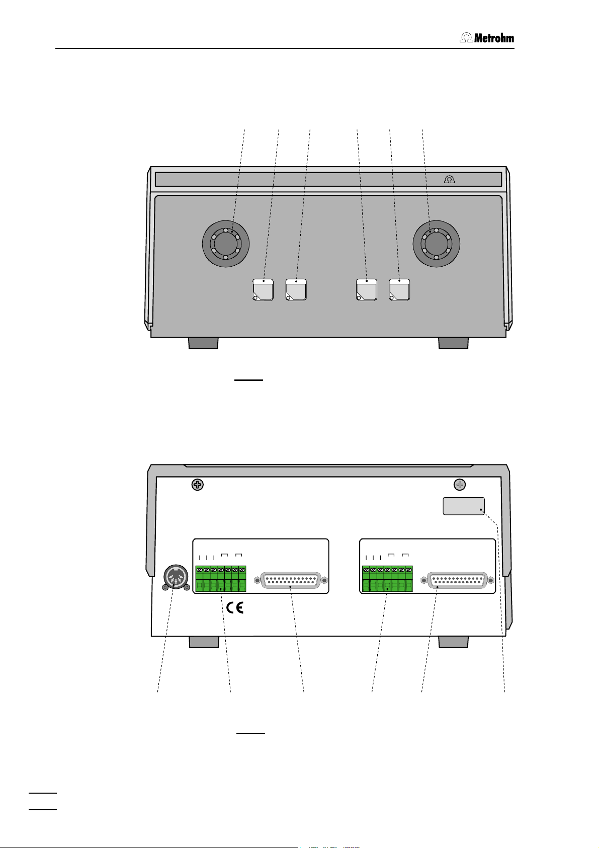
: Front of 812 Valve Unit
Fig. 1
65
Metrohm
FILL INJECT
B
Type: 1.812.00X0
Nr.: XX XXX
External
Power
24VDC/2A
5VDC/0,5A
.
d
n
u
o
r
G
r
t
g
t
.
r
e
s
c
a
l
t
l
l
l
i
F
t
o
e
i
j
n
S
F
I
P
n
I
M
N
M
N
O
U
O
U
R
C
R
732 IC Detector
C
B
978
d
n
u
o
r
G
10 11 12
.
r
t
g
t
.
r
e
s
c
a
l
t
l
l
l
i
F
t
o
e
i
j
n
S
F
I
P
n
I
N
M
M
N
U
O
O
U
R
C
C
R
Made by Metrohm Herisau Switzerland
A
732 IC Detector
Fig. 2
: Rear of 812 Valve Unit
812 Valve Unit
2
Page 6

1.2 Parts and controls
1 Valve A 7 Connection for external supply
connection of power supply unit
(5 V, 0.5 A / 24 V, 2 A)
2 "FILL" key for valve A 8 Terminal block for valve B
(without function for 2.812.0010
instrument version)
Ground, Fill, Inject:
inputs for control of the valve
Pos.Fill:
output signal on switching of the
valve to position "FILL"
Integr.Start:
output signal on switching of the
valve to position "INJECT"
3 "INJECT" key for valve A 9 Connection for 732 IC Detector B
(without function for 2.812.0010
instrument version)
4 "FILL" key for valve B
(without function for 2.812.0010
instrument version)
10 Terminal block for valve A
Ground, Fill, Inject:
inputs for control of the valve
Pos.Fill:
output signal on switching of the
valve to position "FILL"
Integr.Start:
output signal on switching of the
valve to position "INJECT"
5 "INJECT" key for valve B
11 Connection for 732 IC Detector A
(without function for 2.812.0010
instrument version)
6 Ventil B
(not available for 2.812.0010
12 Model plate
with serial number
instrument version)
812 Valve Unit
3
Page 7

1 Introduction
1.3 Information on the Instructions for Use
Please read through these Instructions for Use carefully before you put
the 812 Valve Unit into operation. The Instructions for Use contain
information and warnings to which the user must pay attention in order
to assure safe operation of the instrument.
1.3.1 Organization
These 8.812.1003 Instructions for Use for the 812 Valve Unit provide
a comprehensive overview of the installation, startup procedure, operation and technical specifications of this instrument. The Instructions for
Use are organized as follows:
Section 1 Introduction
General description of instrument, parts and controls
and safety notes
Section 2 Installation
Mains connection, electrical connection,
connection of accessories
Section 3 Operation
Manual operation and operation via «IC Net»
Section 4 Appendix
Technical data, standard equipment, options, warranty,
declarations of conformity, index
To find the required information on the instruments you will find it an
advantage to use either the Table of contents or the Index at the
back.
812 Valve Unit
4
Page 8
1.3 Information on the Instructions for Use
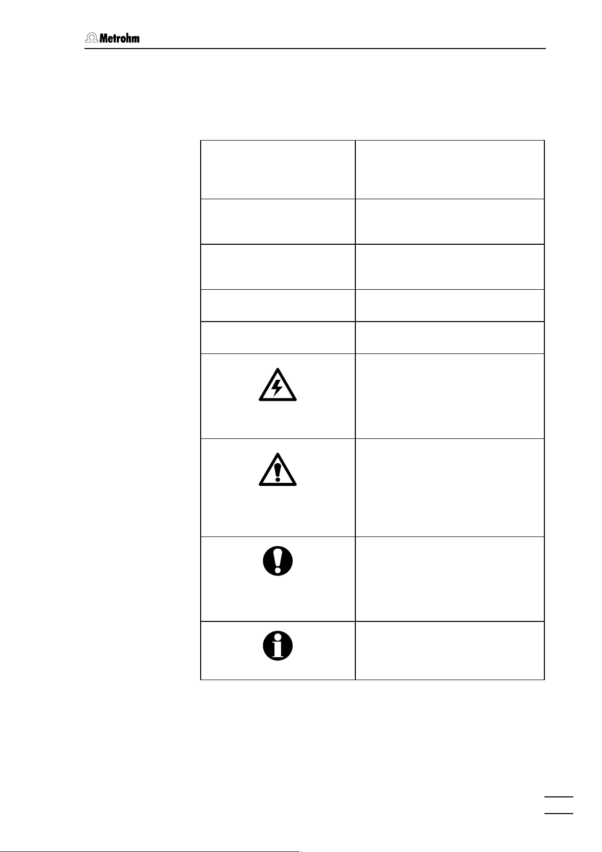
1.3.2 Notation and pictograms
The following notations and pictograms (symbols) are used in these Instructions for Use:
Range Menu item, parameter or entry
value
in «IC Net» program
SYSTEM STATE Program window
in «IC Net» program
<OK> Button
in «IC Net» program
[ FILL ] Switch or key
7 Part or control of 812
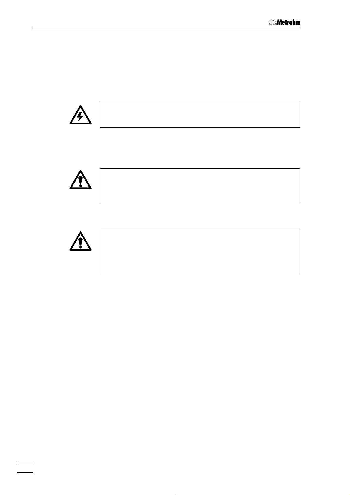
Hazard
This symbol draws attention to a
possible danger to life or of injury if
the associated directions are not
followed correctly.
Warning
This symbol draws attention to
possible damage to instruments or
instrument parts if the associated
directions are not followed correctly.
Caution
This symbol marks important
information. First read the associated directions before you continue.
812 Valve Unit
Comment
This symbol marks additional
information and tips.
5
Page 9
1 Introduction
1.4 Safety notes
While electrical safety in the handling of the 812 Valve Unit is assured in
the context of the specifications IEC 61010-1 (protection class 1), the
following points should be noted:
• Mains connection
The mains connection must be effected in accordance with the
instructions in section 2.2.
• Opening the instrument
Inside the instrument there are no parts which must be set or adjusted
by the user.
If the 812 Valve Unit is connected to the power supply, the instrument
must not be opened nor must parts be removed from it. Hence,
before opening the instrument, always ensure that the power supply
unit is disconnected from connection 7!
• Protection against static charges
Electronic components are sensitive to static charging and can be
destroyed by discharges. Before you touch any of the components
inside the 812 Valve Unit, you should earth yourself and any tools you
are using by touching an earthed object (e.g. housing of the instrument or a radiator) to eliminate any static charges which exist.
812 Valve Unit
6
Page 10

2.1 Setting up the instrument
2 Installation
2.1 Setting up the instrument
2.1.1 Packaging
The 812 Valve Unit is supplied together with the separately packed accessories in special packagings containing shock-absorbing foam linings designed to provide excellent protection. The instrument itself is
packed in an evacuated polyethylene bag to prevent the ingress of
dust. Please store all these special packagings as only they assure
transport of the instrument free from damage.
2.1.2 Check
After receipt, immediately check whether the shipment is complete and
has arrived without damage (compare with delivery note and list of accessories in section 4.2). In the case of transport damage, see instructions in section 4.4.1 "Warranty".
2.1.3 Location
Position the instrument in the laboratory at a location convenient for operation, free from vibrations and protected against a corrosive atmosphere and contamination by chemicals.
2.1.4 Arrangement of the instruments
The 812 Valve Unit can be piled up together with other IC instruments
(e.g. 732, 733, 709).
812 Valve Unit
7
Page 11

2 Installation
2.2 Mains connection
The 812 Valve Unit is operated with the 6.2152.000 Power supply unit
which automatically adjusts itself to the existing mains voltage
(100…240 V) and frequency (50…60 Hz).
The power supply unit is connected to the mains using one of the following mains cables
• 6.2122.020 with plug SEV 12 (Switzerland, …)
• 6.2122.040 with plug CEE(7), VII (Germany, …)
• 6.2133.070 with plug NEMA 5-15 (USA, …)
which are three-cored and fitted with a plug with an earthing pin.
The cable permanently mounted to the power supply unit is plugged
into connection 7 at the 812 Valve Unit (see Fig. 2). The operational
readiness is shown by the LEDs lighting up on the "FILL" or "INJECT"
keys.
2.3 Electrical connection
2.3.1 Connection at the 762 IC Interface
Always switch off 762 IC Interface and 812 Valve Unit before you
connect the two instruments.
The connection of the 812 Valve Unit at the 762 IC Interface enables the
three following functions:
• Control of valve A by the 762 IC Interface
via remote line
• Control of valve B by the 762 IC Interface
via remote line
• Automatic start of data acquisition at the
762 IC Interface by switching valve A or valve B
to the "INJECT" position
For instrument connection proceed as follows (see Fig. 3):
1 Connection for control of valve A
• Connect the plugs inscribed with "GND", "INJECT" and "FILL"
of the 6.2128.100 cable to the connections "Ground", "Fill"
and "Inject" on the terminal block 10 of the 812 Valve Unit
(see Fig. 2).
• Connect the plug inscribed with "Inject NO" of the 6.2128.100
cable to the desired remote line 1...7 "Events - Run" at the
762 IC Interface and the plug inscribed with "Inject COM" to
the same remote line "Events - COM" (see Fig. 5 Instructions
for use 762).
812 Valve Unit
8
Page 12

2.3 Electrical connection
6.2128.100
6.2128.100
6.2115.070
BA
812762
Fig. 3
: Connection of 812 Valve Unit 812 at 762 IC Interface
• Connect the plug inscribed with "LOAD NO" of the
6.2128.100 cable at the desired remote line 1...7 "Events -
Run" at the 762 IC Interface and the plug inscribed with
"LOAD COM" to the same remote line "Events - COM" (see
Fig. 5 Instructions for use 762).
2 Connection for control of valve B
• Connect the plugs inscribed with "GND", "INJECT" and "FILL"
of the 6.2128.100 cable to the connections "Ground", "Fill"
and "Inject" on the terminal block 8 of the 812 Valve Unit (see
Fig. 2).
• Connect the plug inscribed with "Inject NO" of the 6.2128.100
cable to the desired remote line 1...7 "Events - Run" at the
762 IC Interface and the plug inscribed with "Inject COM" to
the same remote line "Events - COM" (see Fig. 5 Instructions
for use 762).
• Connect the plug inscribed with "LOAD NO" of the
6.2128.100 cable at the desired remote line 1...7 "Events -
Run" at the 762 IC Interface and the plug inscribed with
"LOAD COM" to the same remote line "Events - COM" (see
Fig. 5 Instructions for use 762).
3 Connection for external start (option)
• Connect the 6.2115.070 cable to the connections "Integr.
Start - RUN" and "Integr. Start - COM" on the terminal block
10 (valve A) or 8 (valve B) of the 812 Valve Unit (see Fig. 2).
• Connect the other end of the 6.2115.070 cable to the remote
lines "Events - Start - Run" and "Events - Start - Com" at
the 762 IC Interface (see Fig. 5 Instructions for use 762).
2.3.2 Connection at 817 Bioscan
The connection of the 812 Valve Unit to the 817 Bioscan is described in
detail in the Instructions for Use 817.
812 Valve Unit
9
Page 13

2 Installation
2.4 Connections at injection valve
2.4.1 General information
The two six-way valves at the 812 Valve Unit each have 6 connections
for capillaries which are switched as follows:
Fill
45
36
12
: Switching of injection valves
Fig. 4
Connections 1 and 2 of the valve are normally used for supply of sample solution, connections 4 and 5 for eluent supply, and connections 3
and 6 for sample loop installation. For solution supply in the low pressure range (sample feed by use of a syringe or a peristaltic pump), the
6.1803.020 PTFE capillary (i.d. 0.97 mm) is used; in the high pressure
range, the 6.1831.010 PEEK capillary (i.d. 0.25 mm) is used. For both
capillaries, a 6.2744.010 PEEK compression fitting is used as connector.
Inject
45
36
12
2.4.2 Attaching standard accessories
The standard accessories supplied with the 812 Valve Unit can be used
to equip one valve for manual filling of the sample loop. Proceed as follows (see Fig. 5):
1 Connecting the syringe
• Cut off a piece of the 6.1803.020 PTFE capillary to the de-
sired length (at best using the optionally available 6.2621.080
tubing cutter) and fit it on both sides with a 6.2744.010 PEEK
compression fitting (do not tighten too firmly).
• Screw one end of the PTFE capillary 13 to connection 1 of
the injection valve.
• Screw the other end of the PTFE capillary 13 to the
6.2744.120 coupling.
• Push 6.2816.020 syringe (without needle) as far as it will go
into the connection of the 6.2744.120 coupling.
812 Valve Unit
10
Page 14

2.4 Connections at injection valve
17 16
Fig. 5
Syringe tubing
13
6.1803.020 PTFE tubing with
6.2744.120 coupling and
6.2816.020 syringe
14 Aspirating tubing
6.1803.020 PTFE tubing for
aspirating the sample
15 Sample loop
6.1825.210 PEEK sample
loop (20 µL )
45
15
36
21
13 14
: Connection at injection valve
16 Eluent outlet
6.1831.010 PEEK
capillary
17 Eluent inlet
6.1831.010 PEEK
capillary
2 Connecting the aspirating tubing
• Cut off a piece of the 6.1803.020 PTFE capillary to the de-
sired length (at best using the optionally available 6.2621.080
tubing cutter) and fit it on one side with a 6.2744.010 PEEK
compression fitting (do not tighten too firmly).
• Screw this end of the aspirating tubing 14 to connection 2 of
the injection valve.
3 Connecting the sample loop
• Fit the 6.1825.210 sample loop on both sides with a
6.2744.010 compression fitting.
• Screw the sample loop 15 (20 µL) to connections 3 and 6 of
the injection valve.
4 Connecting the eluent supply
• Screw the PEEK capillary 17 for eluent supply from the high
pressure pump to connection 5 of the injection valve.
5 Connecting the separating column
• Screw the PEEK capillary 16 for eluent supply to the separat-
ing column to connection 4 of the injection valve.
812 Valve Unit
11
Page 15

2 Installation
2.5 Software installation
The PC program «IC Net 2.1» is required for the operation of the 812
Valve Unit by a PC. This program runs under Windows 95, Windows 98,
Windows NT and Windows 2000 operating systems and is installed according to section 1.4.2 of the «IC Net» Instructions for Use.
The installation of the 812 Valve Unit is described in section 6.11 of the
«IC Net» Instructions for Use.
812 Valve Unit
12
Page 16

3.1 Manual operation
3 Operation
3.1 Manual operation
FILL
Switch instrument on/off
The 812 Valve Unit is switched on and off by connecting/disconnecting the 6.2152.000 power supply unit attached to
connection 7 (see section 2.2).
After the instrument has been connected to the mains the LEDs
on the "FILL" or "INJECT" keys light up and show that the
instrument is ready for use.
Switch to "FILL" position
By pressing the "FILL" key, the injection valve A or B is switched
to the "FILL" position.
Lighting up of the LED in the "FILL" key indicates the "FILL"
position.
Fill
45
36
12
INJECT
Switch to "INJECT" position
By pressing the "INJECT" key, the injection valve A or B is
switched to the "INJECT" position.
Lighting up of the LED in the "INJECT" key indicates the "INJECT"
position.
Inject
45
36
12
812 Valve Unit
13
Page 17

3 Operation
3.2 Operation via «IC Net»
This section describes only the most important points concerning the
operation of the 812 Valve Unit. For further details please refer to the
«IC Net» Instructions for Use and to the on-line help in the PC program.
3.2.1 812 Valve Unit icon
2.812.0010 Valve Unit
with 1 injector
2.812.0020 Valve Unit
with 2 injectors
3.2.2 Settings in the "812 Valve Unit" window
The 812 Valve Unit window for parameter settings is opened by selecting
Open menu option with the right mouse button or by double-clicking
the
the 812 icon in the system window. It consists of the three tabs
Program and Links.
Manual
The Manual tab of the 812 Valve Unit window is used for manual operation of the injection valves.
Manual,
812 Valve Unit
14
Page 18

3.2 Operation via «IC Net»
Valve A
<Fill> Switch valve A to "FILL" position.
<Inject> Switch valve A to "INJECT" position.
Valve B
<Fill> Switch valve B to "FILL" position.
<Inject> Switch valve B to "INJECT" position.
Time program
On the Program tab of the 812 Valve Unit window a user-defined time
program can be entered. This program starts automatically as defined
Start mode window either at the moment the determination is star-
in the
Start with determination) or at the moment the sample is injected
ted (
Start with inject).
(
Time (1st column) Time at which program instruction is applied.
Range:
If no time is entered, the program instruction is
applied together with the last instruction with
time entry.
Instruction (2nd column) Program instruction (see below).
Parameter (3rd column) Parameter for program instruction (see below).
ENABLED Enable program start (a disabled program is
not started).
<Add> Add new program instruction.
<Delete> Delete selected program instruction.
<Verify> Test the time program (error messages are dis-
played if program is wrong).
0.0 ... 999.9 min
812 Valve Unit
15
Page 19

3 Operation
List of program instructions
The following program instructions can be added to the time program
on the
Instruction Parameter entry Meaning
ValveA fill, inject Switch injection valve A to "inject" or
ValveB fill, inject Switch injection valve B to "inject" or
Program page:
"
fill" position.
"
fill" position.
Links
The Links tab of the 812 Valve Unit window is used for COM port selection and settings (details see IC Net Instructions for Use).
812 Valve Unit
16
Page 20

4.1 Technical data
4 Appendix
4.1 Technical data
Parts and controls
Keypad
Chemically resistant membrane keypad made of
polyester with function keys
Indicators LEDs for display of valve position
Power supply
External External supply via DIN connector:
5 V / 0.5 A
24 V / 2 A (transient, 200…300 ms)
6
3
5
7
1
4
2
1 +5 V DC / 0.5 A
2 not assigned
3 +24 V DC / 2 A
4 0 V (digital) *
5 0 V (analog) *
6 Ground
7 Ground
* Pin 4 and Pin 5 must be
connected in the vicinity
of the power source ("zero
point of star")
Valve interfaces
Connection Function
Inputs
0V
10k
10k
Ω
Ω
Ground Ground
+5V
Fill
+5V
Inject
Valve → "FILL"
Valve is switched to the "FILL"
position
Valve → "INJECT"
Valve is switched to the "INJECT"
position
H
L
H
L
> 2 ms
t
P
> 2 ms
t
P
Outputs
COM
RUN
COM
RUN
Position "Fill"
A pulse is outputted when the
valve is switched to the "FILL"
position.
Integrator Start
A pulse is outputted when the
valve is switched to the "INJECT"
position.
H
L
H
L
≅ 250 ms
t
P
≅ 250 ms
t
P
812 Valve Unit
17
Page 21

4 Appendix
Safety specifications
Safety notes The Instructions for Use include information and
warnings, which must be heeded by the user to
assure safe operation of the instrument.
Electromagnetic compatibility (EMC)
Emitted interference Standards met:
EN 50081-1/2, EN55022 (class B)
Immunity to interference Standards met:
EN50082-1
IEC61000-4-2 (class 3)
IEC61000-4-4 (class 4)
IEC61000-4-11
IEC61000-4-14 (class 3)
Ambient temperature
Nominal operating range +5…+45°C
(at 20…80 % atmospheric humidity)
Storage, Transport –40…+70°C
Housing
Material of cover Polyurethane rigid foam (PUR) with fire protection
for fire class UL94VO, FCH-free
Material of base Steel, enameled
Dimensions
Width 255 mm
Height 128 mm
Depth 365 mm
Weight (with accessories) 2.812.0010: 4.3 kg
2.812.0020: 5.1 kg
812 Valve Unit
18
Page 22

4.2 Standard equipment
4.2 Standard equipment
Subject to changes !
All dimensions are given in mm.
The 812 Valve Unit is available in two versions:
• 2.812.0010 Valve Unit with 1 valve
• 2.812.0020 Valve Unit with 2 valves
These instruments include the following parts:
Quant. Order No. Description
2.812.0010
2.812.0020
1 - 1.812.0010 Valve Unit with 1 valve
- 1 1.812.0020 Valve Unit with 2 valves
1 1 6.1803.020 PTFE capillary
Length L = 5 m
1 1 6.1825.210 Sample loop aus PEEK (20 µL)
for injection valve; incl. 2 PEEK
compression fittings (6.2744.010)
1 1 6.1831.010 PEEK capillary
Length L = 3 m
Diameter d = 0.25 mm
812 Valve Unit
1 1 6.2122.0X0 Mains cable
to customer's specifications:
Cable socket
Type IEC 320/C 13 Type SEV 12 (CH…)............................... 6.2122.020
Type IEC 320/C 13 Type CEE (7), VII (D…)........................... 6.2122.040
Type CEE (22), V Type NEMA 5-15 (USA…) ...................... 6.2122.070
1 2 6.2128.100 Connecting cable
For connection 812 – 762/817
1 1 6.2152.000 Power supply unit
1 2 6.2744.010 PEEK compression fitting
For the connection of 6.1831.010 PEEK
capillaries or 6.1803.020 PTFE capillaries,
set of 5
Cable connector
26
19
Page 23

4 Appendix
Quant. Order No. Description
2.812.0010
2.812.0020
1 1 6.2744.120 Coupling 1⁄16" – Luer
Coupling between 6.2744.010 PEEK
compression fitting and 6.2816.020
Syringe
1 1 6.2816.020 Syringe
made of PP, volume = 10 mL;
for manual filling of the sample loop
1 1 8.812.1003 Instructions for Use (English)
for 812 Valve Unit
22
76
4.3 Optional accessories
Order No. Description
6.1825.XXX Sample loop made of PEEK
For injection valve; incl. 2 PEEK compression
fittings (6.2744.010)
6.1825.230: volume = 10 µL
6.1825.210: volume = 20 µL
6.1825.220: volume = 100 µL
6.2115.070 Cable
Connection cable 812/762 for external start
6.2621.080 Capillary tubing cutter
for 6.1831.010 PEEK capillaries and
6.1803.020 PTFE capillaries
incl. 5 additional blades
55
118
812 Valve Unit
20
Page 24

4.4 Warranty and conformity
4.4 Warranty and conformity
4.4.1 Warranty
The warranty on our products is limited to defects that are traceable to
material, construction or manufacturing error that occur within 12
months from the day of delivery. In this case, the defects will be rectified in our workshops free of charge. Transport costs are to be paid by
the customer.
For day and night operation, the warranty is limited to 6 months.
Glass breakage in the case of electrodes or other parts is not covered
by the warranty. Checks, which are not a result of material or manufacturing faults, are also charged during the warranty period. For parts of
outside manufacture insofar as these constitute an appreciable part of
our instrument, the warranty stipulations of the manufacturer in question
apply.
With the regard to the guarantee of accuracy, the technical specifications in the instruction manual are authoritative.
Concerning defects in material, construction or design as well as the
absence of guaranteed features, the orderer has no rights or claims except those mentioned above.
If damage of the packaging is evident on receipt of a consignment or if
the goods show signs of transport damage after unpacking, the carrier
must be informed immediately and a written damage report demanded.
Lack of an official damage report releases Metrohm from any liability to
pay compensation.
If any instruments and parts have to be returned, the original packaging
should be used if at all possible. This applies above all to instruments,
electrodes, burette cylinders and PTFE pistons. Before embedment in
wood shavings or similar material, the parts must be packed in a dustproof package (for instruments, use of a plastic bag is imperative). If
open assemblies are enclosed in the scope of delivery that are sensitive to electromagnetic voltages (e.g. data interfaces etc.) these must
be returned in the associated original protective packaging (e.g. conductive protective bag). (Exception: assemblies with built-in voltage
source belong in a non-conductive protective packaging). For damage,
which arises as a result of non-compliance with these instructions, no
warranty responsibility whatsoever will be accepted by Metrohm.
812 Valve Unit
21
Page 25

4 Appendix
4.4.2 EU Declaration of conformity
EU Declaration of Conformity
The METROHM AG company, Herisau, Switzerland hereby certifies, that the
instrument:
812 Valve Unit
meets the requirements of EC Directives 89/336/EEC and 73/23/EEC..
Source of the specifications:
EN 50081-1/2 Electromagnetic compatibility, basic specification;
Emitted Interference
EN 50082-1 Electromagnetic compatibility, basic specification;
Interference Immunity
Description of the instrument:
Instrument with 1 or 2 electrically driven six-way valves.
Herisau, April 4, 2001
Dr. J. Frank Ch. Buchmann
Development Manager Production and
Quality Assurance Manager
812 Valve Unit
22
Page 26

4.4 Warranty and conformity
4.4.3 Certificate of conformity and system validation
Certificate of Conformity and System Validation
This is to certify the conformity to the standard specifications for electrical appliances and accessories, as well as to the standard specifications for security and
to system validation issued by the manufacturing company.
Name of commodity: 812 Valve Unit
Name of manufacturer: Metrohm Ltd., Herisau, Switzerland
Principal technical information: Voltages: 100-240 V
Frequency: 50-60 Hz
This Metrohm instrument has been built and has undergone final type testing
according to the standards:
EN50081-1/2, EN50082-1, EN55022 (class B), IEC61000-4-2 (class 3),
IEC61000-4-4 (class 4), IEC61000-4-11, IEC61000-4-14 (class 3)
— Electromagnetic compatibility
It has also been certified by the Swiss Electrotechnical Association (SEV), which
is member of the International Certification Body (CB/IEC).
The technical specifications are documented in the instruction manual.
Metrohm Ltd. is holder of the SQS-certificate of the quality system ISO 9001 for
quality assurance in design/development, production, installation and servicing.
Herisau, April 4, 2001
Dr. J. Frank Ch. Buchmann
Development Manager Production and
Quality Assurance Manager
812 Valve Unit
23
Page 27

4 Appendix
4.5 Index
A
Ambient temperature............................ 18
Appendix............................................... 17
Arrangement of the instruments..............7
Aspirating tubing 14
Figure................................................ 11
Installation......................................... 11
Attaching standard accessories .......... 10
C
Cable (6.2115.070)............................ 9,20
Cable (6.2128.100)......................... 8,9,19
Capillary tubing cutter
(6.2621.080) ................................ 10,20
Caution ....................................................5
Certificate of conformity and
system validation.............................. 23
Check ......................................................7
Comment.................................................5
Conformity ............................................ 22
Connection
Aspirating tubing .............................. 11
Bioscan 817.........................................9
Eluent supply.................................... 11
Sample loop ..................................... 11
Separating column ........................... 11
Syringe.............................................. 10
Connection 7
Connect power supply unit .................8
Figure...................................................3
Connection 9
Figure...................................................3
Connection 11
Figure...................................................3
Connections at injection valve ............. 10
Coupling (6.2744.120).......................... 20
D
Declaration of conformity ..................... 22
Dimensions........................................... 18
E
Earthing ............................................... 6,8
Electrical connection ...............................8
Electrical safety........................................6
Electromagnetic compatibility.............. 18
Eluent inlet 17
Figure................................................ 11
Eluent outlet 16
Figure................................................ 11
EMC ...................................................... 18
Emitted interference ............................. 18
EU Declaration of conformity ............... 22
F
Front ........................................................2
H
Hazard.....................................................5
Housing .................................................18
I
Immunity to interference .......................18
Information on the
Instructions for Use ............................. 4
Installation ...............................................7
Instructions for Use 8.812.1003..............4
Instrument description ............................1
Introduction .............................................1
K
Key 2 (FILL)
Figure ..................................................3
Operation ..........................................13
Key 3 (INJECT)
Figure ..................................................3
Operation ..........................................13
Key 4 (FILL)
Figure ..................................................3
Operation ..........................................13
Key 5 (INJECT)
Figure ..................................................3
Operation ..........................................13
Keypad .................................................. 17
L
Links ......................................................16
List of program instructions ..................16
Location................................................... 7
M
Mains cable ...........................................19
Mains connection
Procedure............................................ 8
Safety notes.........................................6
Manual operation ..................................13
Model plate 12
Figure ..................................................3
N
Notation ...................................................5
O
Opening the instrument ..........................6
Operation...............................................13
Operation via IC Net.............................. 14
Optional accessories ............................20
Organization ............................................4
P
Packaging ...............................................7
Parts and controls ................................... 2
PEEK capillary (6.1831.010) ............10,19
PEEK compression fitting
(6.2744.010).................................10,19
Pictograms .............................................. 5
Power supply ........................................17
Power supply unit..........................8,13,19
Program instructions............................. 16
Protection class....................................... 6
PTFE capillary (6.1803.020)............. 10,19
R
Rear......................................................... 2
S
Safety notes ............................................6
Safety specifications ............................. 18
Sample loop 15
Figure ................................................ 11
Installation ......................................... 11
Ordering designation ........................ 19
Sample loop (6.1825.XXX).................... 20
Setting up the instrument........................ 7
Software installation .............................. 12
Standard equipment ............................. 19
Static charges .........................................6
Storage.................................................. 18
Switch instrument on/off .......................13
Switching of injection valves ................. 10
Syringe (6.2816.020)........................ 10,20
Syringe tubing 13
Figure ................................................ 11
Installation ......................................... 10
T
Technical data....................................... 17
Terminal block 8
Connection of 6. 2115.070 cable .......9
Connection of 6.2128.100 cable ........9
Figure .................................................. 3
Technical data................................... 17
Terminal block 10
Connection of 6. 2115.070 cable .......9
Connection of 6.2128.100 cable ........8
Figure .................................................. 3
Technical data................................... 17
Time program........................................15
Transport................................................. 7
Transport damage ................................21
V
Valve 1 (A)
Figure .................................................. 3
Operation ..........................................13
Valve 6 (B)
Figure .................................................. 3
Operation ..........................................13
Valve A..............................................15,16
Valve B.............................................. 15,16
Valve interfaces ..................................... 17
W
Warning ................................................... 5
812 Valve Unit
24
 Loading...