

Page 1
807 Dosing Unit
Manual
8.807.8002EN
Page 2

Page 3

Metrohm AG
CH-9101 Herisau
Switzerland
Phone +41 71 353 85 85
Fax +41 71 353 89 01
info@metrohm.com
www.metrohm.com
807 Dosing Unit
8.807.8002EN
Manual
01.2011 dm/ek
Page 4

Teachware
Metrohm AG
CH-9101 Herisau
teachware@metrohm.com
This documentation is protected by copyright. All rights reserved.
Although all the information given in this documentation has been
checked with great care, errors cannot be entirely excluded. Should you
notice any mistakes please send us your comments using the address
given above.
Documentation in additional languages can be found on
http://products.metrohm.com under Literature/Technical documenta-
tion.
Page 5

■■■■■■■■■■■■■■■■■■■■■■
Table of contents
1 Introduction 1
1.1 Instrument description ......................................................... 1
1.2 Model versions ...................................................................... 1
1.3 About the documentation ................................................... 2
1.3.1 Symbols and conventions ........................................................ 2
1.4 Safety instructions ................................................................ 3
1.4.1 Tubing and capillary connections ............................................. 3
1.4.2 Flammable solvents and chemicals ........................................... 3
1.5 Recycling and disposal ......................................................... 4
2 Construction of the 807 Dosing Unit 5
2.1 Total view .............................................................................. 5
2.2 Components of the 807 Dosing Unit .................................. 6
Table of contents
2.3 Cylinder unit .......................................................................... 8
2.4 Connectors (ports) of the 807 Dosing Unit ........................ 9
3 Installation 10
3.1 Greasing the dosing unit .................................................... 10
3.2 Mounting the storage vessel and the holder ................... 11
3.3 Mounting the adsorber tube ............................................. 14
3.4 Mounting filling tubes ........................................................ 15
3.5 Mounting the dosing unit onto the bottle ....................... 15
3.5.1 Mounting the dosing unit onto the bottle .............................. 15
3.5.2 Mounting the dosing tubing and buret tips ............................ 17
3.5.3 Buret tips ............................................................................... 18
3.6 Avoiding air bubbles .......................................................... 19
3.7 Disassembling the dosing unit .......................................... 21
3.7.1 Disassembling the dosing unit ................................................ 21
3.8 Assembling the dosing unit ............................................... 26
3.8.1 Inserting the dosing piston .................................................... 26
3.8.2 Attaching cylinder unit in distributor ...................................... 28
3.8.3 Attaching the housing ........................................................... 28
807 Dosing Unit
4 Handling and maintenance 31
4.1 Care and upkeep ................................................................. 31
4.1.1 Cleaning dosing cylinder and dosing piston ........................... 31
4.1.2 Cleaning valve disc and distributor disc .................................. 32
■■■■■■■■
III
Page 6

Table of contents
■■■■■■■■■■■■■■■■■■■■■■
4.1.3 Discs adhere to one another .................................................. 33
4.1.4 Resistance and materials ........................................................ 34
4.2 Quality Management and validation with Metrohm ....... 35
4.3 GLP - Validation .................................................................. 36
5 Troubleshooting 37
5.1 Problems ............................................................................. 37
6 Appendix 40
6.1 Buret data ........................................................................... 40
6.2 Dosing accuracy .................................................................. 41
6.2.1 Typical measurement deviation .............................................. 41
6.2.2 The ISO/EN/DIN standard 8655-3 ........................................... 41
7 Accessories 43
7.1 Scope of delivery ................................................................ 43
7.1.1 807 Dosing Unit 6.3032.xxx .................................................. 43
7.2 Optional accessories ........................................................... 47
Index 54
■■■■■■■■
IV
807 Dosing Unit
Page 7

■■■■■■■■■■■■■■■■■■■■■■
Table of figures
Figure 1 807 Dosing Unit ................................................................................ 5
Figure 2 807 Dosing Unit - Components ......................................................... 6
Figure 3 Cylinder unit ...................................................................................... 8
Figure 4 807 Dosing Unit - Ports ..................................................................... 9
Figure 5 Removing the housing ..................................................................... 10
Figure 6 Greasing the centering tube and interior edges of the housing ........ 11
Figure 7 Mounting the storage vessel and the holder .................................... 12
Figure 8 Marking rib on housing and distributor ............................................ 13
Figure 9 Locking the housing ........................................................................ 13
Figure 10 Mounting the adsorber tube ........................................................... 14
Figure 11 Mounting filling tubes ..................................................................... 15
Figure 12 Dosing unit on the reagent bottle .................................................... 16
Figure 13 Mounting the tubing and the buret tip ............................................ 17
Figure 14 Air bubbles in the cylinder ............................................................... 20
Figure 15 Removing the housing ..................................................................... 22
Figure 16 Cylinder unit on the distributor ........................................................ 23
Figure 17 Dosing cylinder damaged ................................................................ 23
Figure 18 Dosing cylinder with dosing piston .................................................. 25
Figure 19 Inserting the dosing piston .............................................................. 26
Figure 20 Centering tube on the dosing cylinder ............................................. 27
Figure 21 Stopper of the dosing piston flush with the upper edge of the hous-
ing .................................................................................................. 27
Figure 22 Marking ribs on the centering tube and edge of the distributor ....... 28
Figure 23 Marking rib on housing and distributor ............................................ 29
Figure 24 Locking the housing ........................................................................ 29
Figure 25 Piston stopper flush with the upper edge of the housing ................. 30
Figure 26 Triangles on the upper side of the dosing unit when the stopcock is set
correctly .......................................................................................... 30
Figure 27 Dosing unit completely mounted ..................................................... 30
Figure 28 Valve disc in the cylinder base ......................................................... 32
Figure 29 Distributor disc with 4 ports (in the distributor) ................................ 32
Figure 30 Data chip and contact pin ............................................................... 41
Table of figures
807 Dosing Unit
■■■■■■■■
V
Page 8

Page 9
■■■■■■■■■■■■■■■■■■■■■■
1 Introduction
1.1 Instrument description
The 807 Dosing Unit is a versatile buret unit which can be operated with a
700 Dosino or 800 Dosino dosing drive. The 807 Dosing Unit is suitable
for precise dosings, titrations, pipetting procedures, sample transfers, etc.
The four inputs and outputs (ports) are designed for flexible use (presuming the presence of a suitable control device).
Thanks to the transparent housing of the 807 Dosing Unit, piston movements and stopcock rotations are visible. This means that even complex
liquid handling applications are easy to monitor. The unobstructed view
into the dosing cylinder also ensures that solutions can be monitored with
respect to the absence of bubbles and the leak-tightness of the cylinder
unit.
1 Introduction
Specifications concerning the dosing unit and the reagent can be stored in
the integrated data chip. This data can be extracted and updated by a
suitable control device.
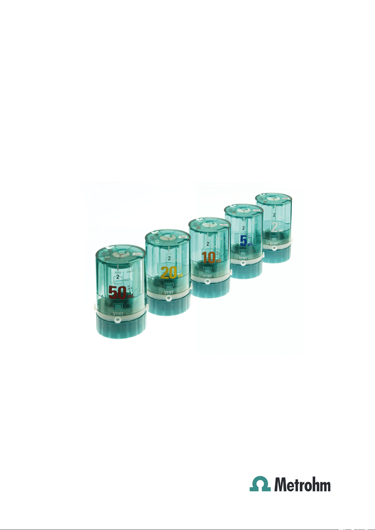
1.2 Model versions
The 807 Dosing Unit is available with cylinder sizes of 2 mL, 5 mL, 10 mL,
20 mL and 50 mL. In addition to glass cylinders, plastic cylinders (ETFE)
specially manufactured for alkali and other aggressive solutions are also
available.
Table 1
Volume Order number
2 mL 6.3032.120
5 mL 6.3032.150
10 mL 6.3032.210
20 mL 6.3032.220
50 mL 6.3032.250
807 Dosing Unit with glass cylinder
807 Dosing Unit
Table 2 807 Dosing Unit with ETFE cylinder
Volume Order number
2 mL 6.1575.120
■■■■■■■■
1
Page 10
1.3 About the documentation
Volume Order number
5 mL 6.1575.150
10 mL 6.1575.210
20 mL 6.1575.220
50 mL 6.1575.250
1.3 About the documentation
CAUTION
Please read through this documentation carefully before putting the
instrument into operation. The documentation contains information
and warnings which the user must follow in order to ensure safe operation of the instrument.
■■■■■■■■■■■■■■■■■■■■■■
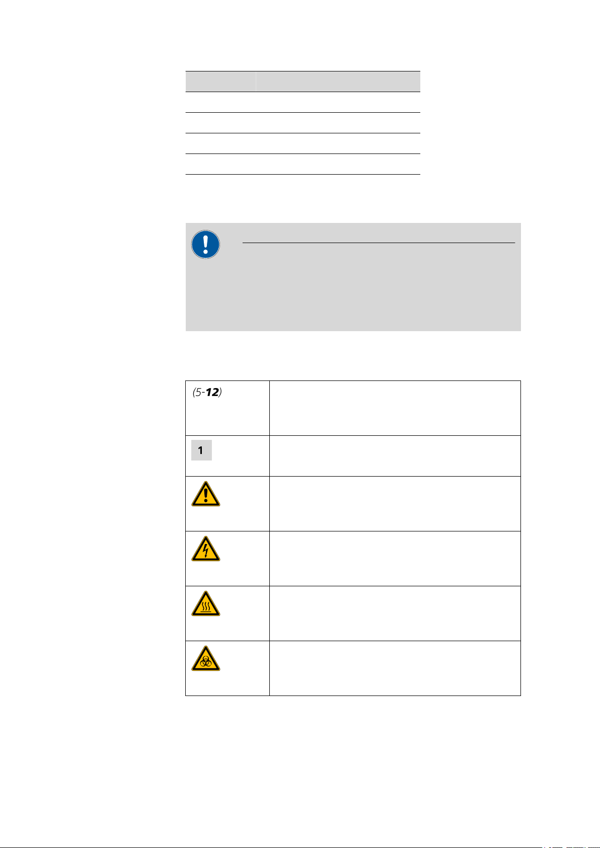
1.3.1 Symbols and conventions
The following symbols and styles are used in this documentation:
Cross-reference to figure legend
The first number refers to the figure number, the
second to the instrument part in the figure.
Instruction step
Carry out these steps in the sequence shown.
Warning
This symbol draws attention to a possible life hazard
or risk of injury.
Warning
This symbol draws attention to a possible hazard due
to electrical current.
Warning
This symbol draws attention to a possible hazard due
to heat or hot instrument parts.
■■■■■■■■
2
Warning
This symbol draws attention to a possible biological
hazard.
807 Dosing Unit
Page 11
■■■■■■■■■■■■■■■■■■■■■■
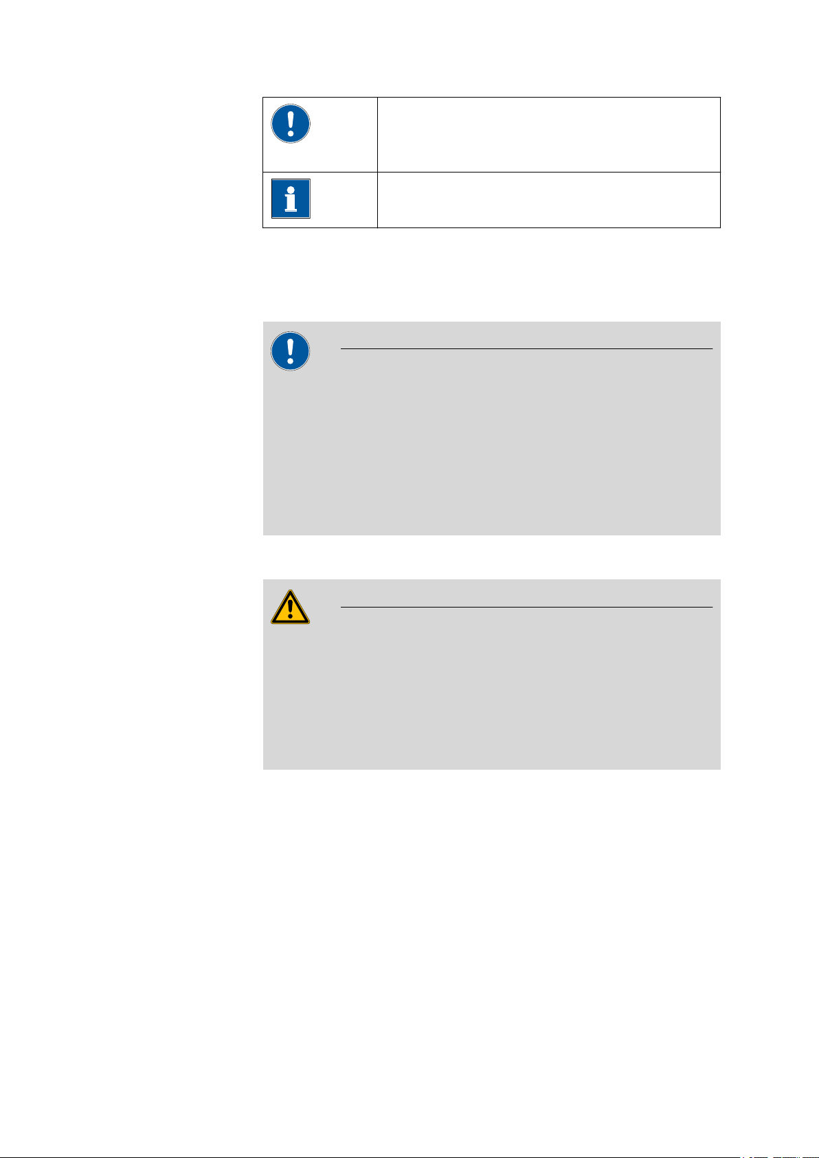
Caution
This symbol draws attention to a possible damage of
instruments or instrument parts.
Note
This symbol marks additional information and tips.
1.4 Safety instructions
1.4.1 Tubing and capillary connections
CAUTION
Leaks in tubing and capillary connections are a safety risk. Tighten all
connections well by hand. Avoid applying excessive force to tubing
connections. Damaged tubing ends lead to leakage. Appropriate tools
can be used to loosen connections.
1 Introduction
Check the connections regularly for leakage. If the instrument is used
mainly in unattended operation, then weekly inspections are mandatory.
1.4.2 Flammable solvents and chemicals
WARNING
All relevant safety measures are to be observed when working with
flammable solvents and chemicals.
■ Set up the instrument in a well-ventilated location.
■ Keep all sources of flame far from the workplace.
■ Clean up spilled fluids and solids immediately.
■ Follow the safety instructions of the chemical manufacturer.
807 Dosing Unit
■■■■■■■■
3
Page 12

1.5 Recycling and disposal
1.5 Recycling and disposal
This product is covered by European Directive 2002/96/EC, WEEE – Waste
from Electrical and Electronic Equipment.
The correct disposal of your old equipment will help to prevent negative
effects on the environment and public health.
More details about the disposal of your old equipment can be obtained
from your local authorities, from waste disposal companies or from your
local dealer.
■■■■■■■■■■■■■■■■■■■■■■
■■■■■■■■
4
807 Dosing Unit
Page 13
■■■■■■■■■■■■■■■■■■■■■■
2
1
2
3
4
5
6
7
8
9
10
11
12
2 Construction of the 807 Dosing Unit
2 Construction of the 807 Dosing Unit
2.1 Total view
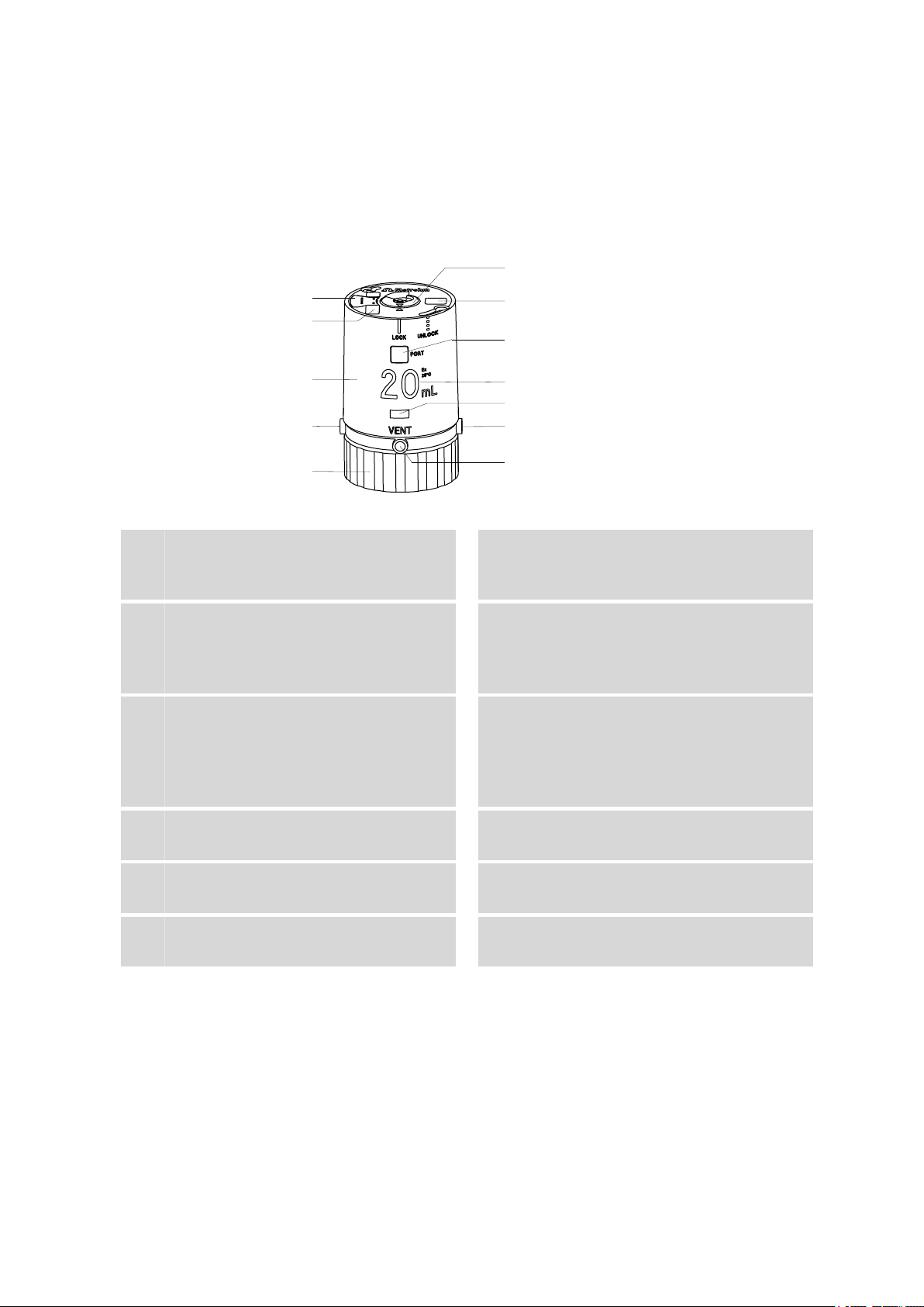
Figure 1 807 Dosing Unit
Data chip
1
Contains all specifications for the dosing
unit.
Housing
3
With data chip, coding magnets, locking
button and specifications concerning the
dosing unit.
Fixing ring
5
For fastening the dosing unit onto a reagent
bottle.
Serial number, order number and bar-
7
code
Nominal volume
9
Volume of the dosing cylinder.
Port 3
11
Dosing port 2. Dosing output for solution.
Coding magnet
2
For automatic recognition of the volume of
the dosing unit.
Port 1
4
Dosing port 1. Dosing output for solution.
Centering tube
6
Is actuated by Dosino and rotates the entire
inner cylinder unit, together with dosing cylinder, cylinder base and the integrated valve
disc.
Port display
8
Displays the port currently opened.
Locking button
10
For locking and unlocking the housing.
VENT port
12
For deaerating the reagent bottle.
807 Dosing Unit
■■■■■■■■
5
Page 14
2.2 Components of the 807 Dosing Unit
1
2
3
4
5
6
7
8
9
10
11
■■■■■■■■■■■■■■■■■■■■■■
2.2 Components of the 807 Dosing Unit
6
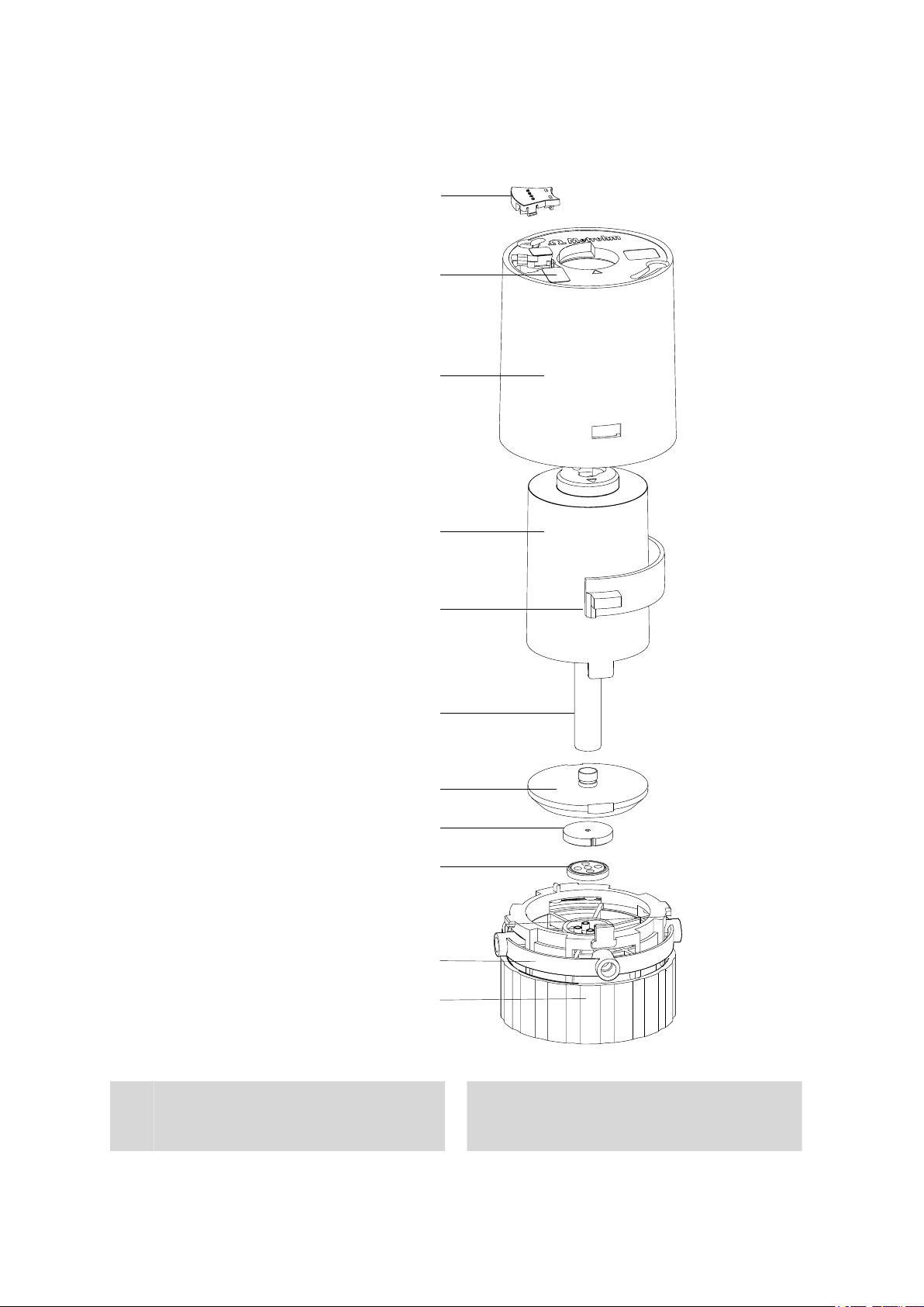
Data chip
1
Contains all specifications for the dosing
unit.
■■■■■■■■
Figure 2 807 Dosing Unit - Components
Coding magnet(s)
2
For automatic recognition of the volume of
the dosing unit.
807 Dosing Unit
Page 15

■■■■■■■■■■■■■■■■■■■■■■
2 Construction of the 807 Dosing Unit
Housing
3
With data chip, coding magnets, locking
button and specifications concerning the
dosing unit.
Material: PETG or PVDF
Spring clip
5
Material: PETG or PVDF
Cylinder base
7
Seals the dosing cylinder and contains the
valve disc.
Material: PTFE / Graphite
Distributor disc
9
The four holes in the distributor disc each
set up a connection with one of the four
ports (input/output) of the dosing unit.
Material: Al 2 O 3 ceramic
Centering tube
4
Is actuated by Dosino and rotates the entire
inner cylinder unit, together with dosing cylinder, cylinder base and the integrated valve
disc.
Material: PETG or PVDF
Dosing cylinder
6
Contains the solution for dosing. Volume
2 mL , 5 mL , 10 mL , 20 mL or 50 mL .
Material: Borosilicate 3.3 or ETFE
Valve disc
8
A hole in the valve disc guides the solution
into one (of four) selected openings in the
distributor disc.
Material: Silicone carbide ceramic
Distributor
10
Contains four ports (input/output) for solutions. The ports are actuated by the distributor disc in the distributor and the valve disc
in the base of the cylinder.
Material: ETFE
Fixing ring
11
For fastening the dosing unit onto a reagent
bottle.
Material: PVDF
807 Dosing Unit
■■■■■■■■
7
Page 16
2.3 Cylinder unit
1
2
3
4
5
2.3 Cylinder unit
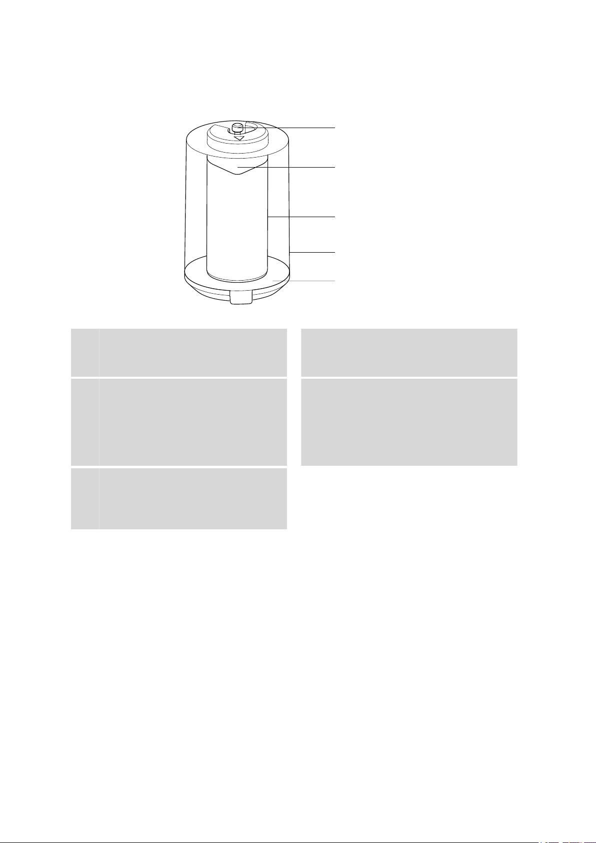
Figure 3 Cylinder unit
■■■■■■■■■■■■■■■■■■■■■■
Piston stopper
1
Coupling for the piston rod of the Dosino.
Dosing cylinder (Glass: 6.1574.XXX,
3
ETFE: 6.1575.XXX)
Contains the solution for dosing. Volume
2 mL , 5 mL, 10 mL, 20 mL or 50 mL.
Material: Borosilicate 3.3 or ETFE
Cylinder base
5
Seals the dosing cylinder and contains the
valve disc.
Material: PTFE / Graphite
Dosing piston
2
For ejecting and aspirating a solution.
Material: ETFE
Centering tube
4
Is actuated by Dosino and rotates the entire
inner cylinder unit, together with dosing cylinder, cylinder base and the valve disc
mounted within.
Material: PETG or PVDF
■■■■■■■■
8
807 Dosing Unit
Page 17
■■■■■■■■■■■■■■■■■■■■■■
1
3
4
5
2
2 Construction of the 807 Dosing Unit
2.4 Connectors (ports) of the 807 Dosing Unit
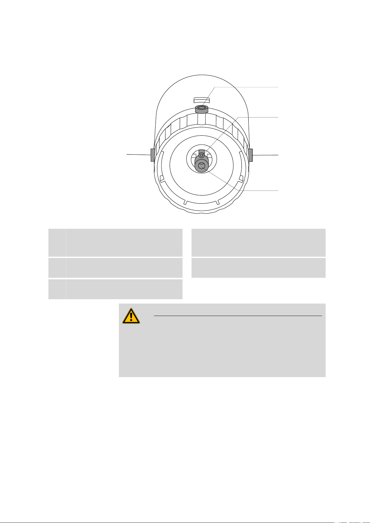
Figure 4 807 Dosing Unit - Ports
Port 1
1
Connector (M6) for the dosing tubing.
Port 4
3
Special port, waste port or recycling port.
Port 2
5
Connector (M6) for the filling tubing.
Port 2 is the fill port in the default configuration. Take care to ensure
that the tubing is firmly screwed in place in order that no air bubbles
will be able to enter during aspiration of the reagent solution. Always
use the 6.2739.000 wrench provided for tightening and unscrewing
tubing connections.
WARNING
VENT
2
Deaeration, connection (M6) for adsorber
tube.
Port 3
4
Connector (M6) for a second dosing tubing.
807 Dosing Unit
■■■■■■■■
9
Page 18
3.1 Greasing the dosing unit
3 Installation
3.1 Greasing the dosing unit
We recommend that the upper side of the centering tube and interior
edges of the upper side of the housing be greased with paraffin grease
6.2803.010 before the dosing unit is used for the first time. This measure
will reduce friction resistance when the centering tube is rotated.
Removing the housing
■■■■■■■■■■■■■■■■■■■■■■
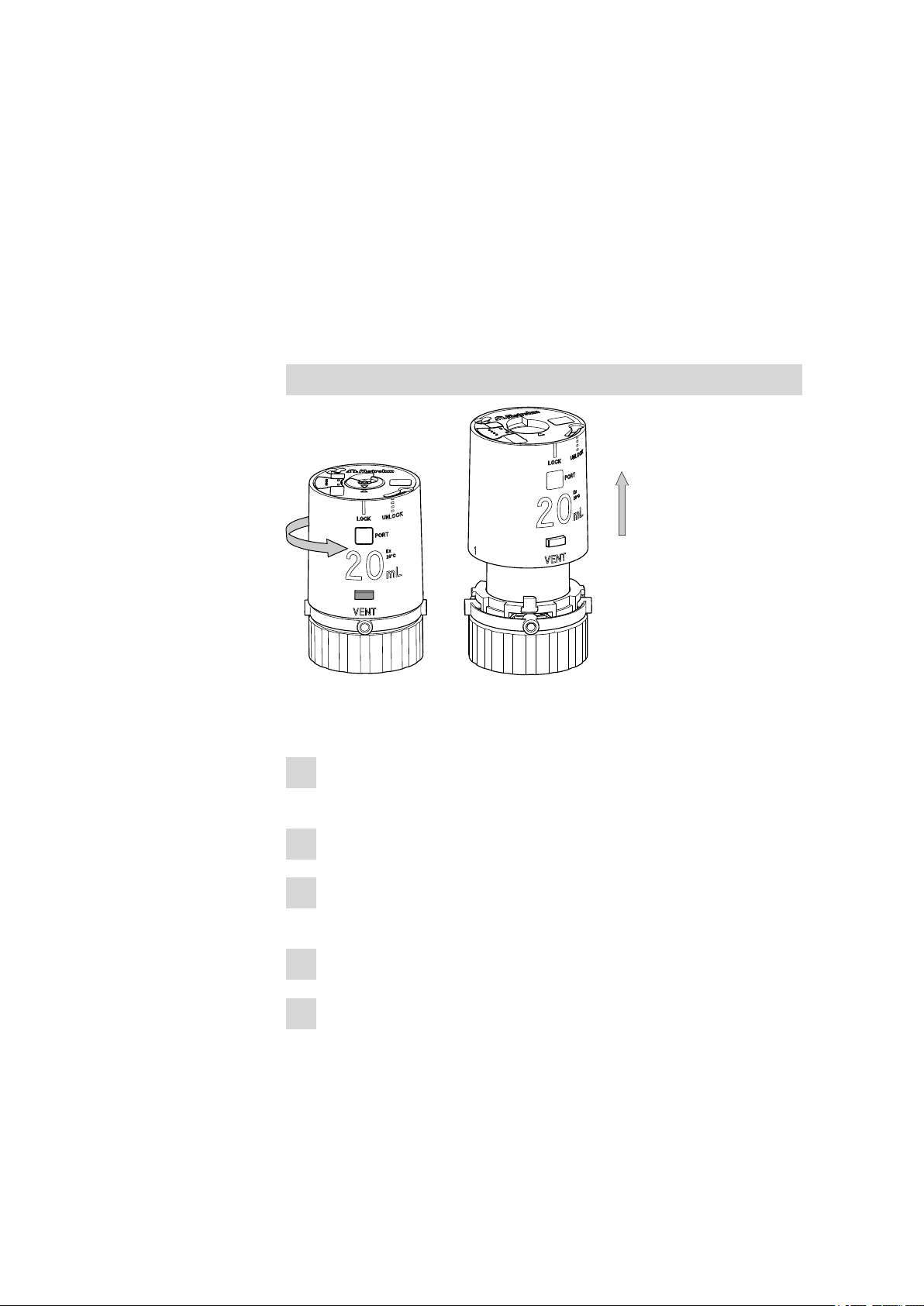
Figure 5
Removing the housing
Remove the housing of the dosing unit as follows:
Place the dosing unit on a flat, level surface so that the lettering of
1
the volume specification faces towards the front.
Keep the locking button pressed down.
2
Rotate the housing of the dosing unit by ca. 1 cm to the right (in
3
counterclockwise direction).
Release the locking button.
4
Carefully raise the housing upward.
5
When removing the housing, take care to ensure that the spring clip
on the interior side of the housing does not slide out of place.
■■■■■■■■
10
807 Dosing Unit
Page 19
■■■■■■■■■■■■■■■■■■■■■■
1
1
2
3 Installation
Greasing the centering tube and housing
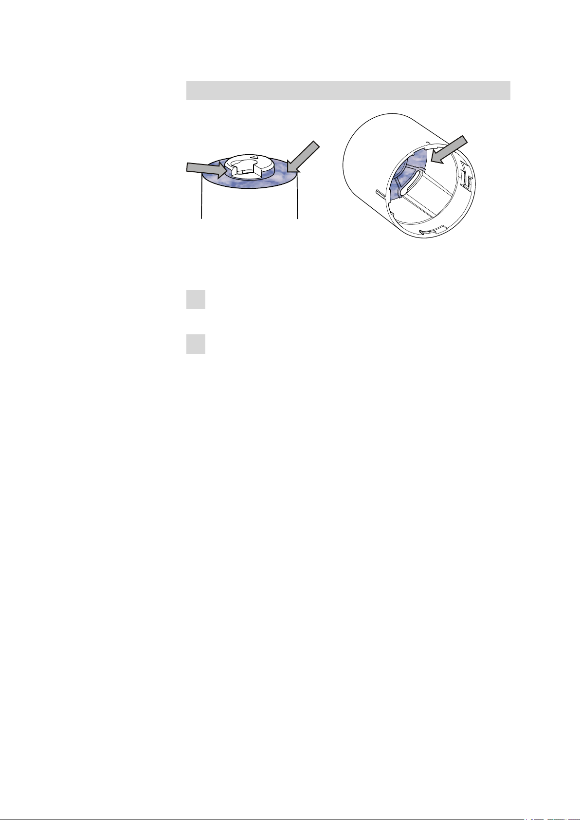
Figure 6 Greasing the centering tube and interior edges of the housing
Grease the centering tube and housing as follows:
Grease the sliding surfaces on the upper side of the centering tube
1
with paraffin grease 6.2803.010.
Grease the sliding surfaces on the interior edge of the housing with
2
paraffin grease 6.2803.010.
3.2 Mounting the storage vessel and the holder
The dosing unit comes equipped with a storage vessel 6.2008.030 with
holder 6.2008.050 for the storage of the buret tip. It should be mounted
when the device is started up for the first time.
The storage vessel serves as a storage container for the buret tip when the
dosing unit is not in use.
The associated holder is used at the same time for mounting a name plate
with the designation of the reagent in the dosing unit. Name plates can
be reordered under the order number 6.2244.020 from any Metrohm
agent.
The dosing unit housing must be removed in order to assemble the storage vessel holder (see "Removing the housing", page 10).
807 Dosing Unit
■■■■■■■■
11
Page 20

3.2 Mounting the storage vessel and the holder
6.2008.030
6.2008.050
6.2244.020
2
3
4
5
1
Mounting the storage vessel and the holder
Figure 7 Mounting the storage vessel and the holder
■■■■■■■■■■■■■■■■■■■■■■
Mount the storage vessel and the holder on the dosing unit as follows:
Rotate the centering tube on the distributor in such a way that the
1
marking rib on the centering tube is lined up with the marking rib on
the edge of the distributor.
Place the holder 6.2008.050 on the edge of the distributor.
2
Place the storage vessel 6.2008.030 for the buret tip in the holder.
3
In order to ensure perfect seating, the rib on the storage vessel must
be guided into the groove on the holder and pushed downward.
The holder can be placed at any one of four positions on the ring of
the distributor.
Slide the name plate 6.2244.020, which has the designation of the
4
reagent in the dosing unit, into the holder.
Slide the housing of the dosing unit onto the centering tube.
5
The centering tube with the cylinder unit must be in correct position
when the housing is attached. You will find a positioning aid on the
rear side of the dosing unit.
■■■■■■■■
12
807 Dosing Unit
Page 21

■■■■■■■■■■■■■■■■■■■■■■
3 Installation
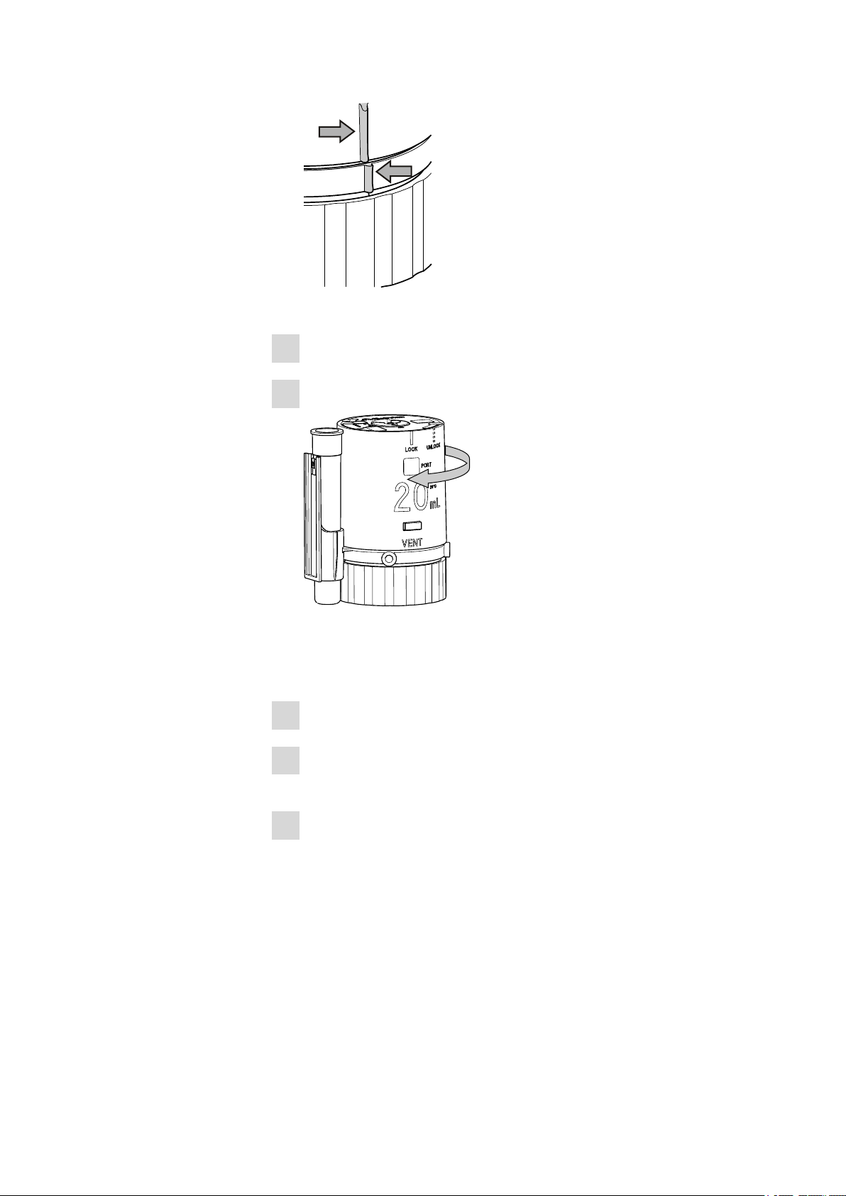
Figure 8 Marking rib on housing and distributor
Locking the housing
Figure 9
Locking the housing
Lock the housing as follows:
Hold the distributor in place.
1
Rotate the housing to the left (in clockwise direction).
2
Once all the parts are lined up with one another, the housing will
snap into place.
807 Dosing Unit
■■■■■■■■
13
Page 22

3.3 Mounting the adsorber tube
6.1619.00
3.3 Mounting the adsorber tube
Figure 10 Mounting the adsorber tube
Mount the adsorber tube as follows:
Fill the adsorber tube 6.1619.000 with an adsorption material
1
required for the reagent.
■■■■■■■■■■■■■■■■■■■■■■
■ Molecular sieve for moisture-sensitive solutions ( e.g. KF solu-
tions).
■ Soda lime for sodium hydroxide solution (CO
Seal the adsorber tube with the appropriate cover.
2
adsorption)
2
A minimum pressure compensation remains ensured.
Screw the adsorber tube to the deaeration port (VENT) of the dos-
3
ing unit.
The adsorber tube should be screwed on a bottle in hanging position
after the assembly of the dosing unit.
The VENT connector deaerates the reagent bottle. It should never be
entirely sealed off. If no adsorber material is required, then the adsorber
tube can be filled with cotton and used as a dust filter.
■■■■■■■■
14
807 Dosing Unit
Page 23

■■■■■■■■■■■■■■■■■■■■■■
6.1829.010
3.4 Mounting filling tubes
3 Installation
Figure 11 Mounting filling tubes
Mount the tubing as follows:
Screw the aspiration tubing 6.1829.010 onto the connector with
1
inner thread (Port 2) on the underside of the dosing unit.
3.5 Mounting the dosing unit onto the bottle
3.5.1 Mounting the dosing unit onto the bottle
A variety of different bottles can be used as storage containers. Amber
glass bottles 6.1608.023, clear glass bottles 6.1608.030 or PE bottles
6.1608.040 of 1 liter volume and GL45 thread.
Suitable thread adapters are available for bottles with other threads (see
Chapter 7.2, page 47).
WARNING
The lip of the bottle should have a plastic decanting ring. Do not use
any mechanical aids for mounting the dosing unit. The upper part of
the housing should still be easy to turn by hand.
807 Dosing Unit
■■■■■■■■
15
Page 24

3.5 Mounting the dosing unit onto the bottle
■■■■■■■■■■■■■■■■■■■■■■
Figure 12 Dosing unit on the reagent bottle
Mount the dosing unit as follows:
Rotate the adsorber tube upward.
1
Fasten the dosing unit onto the filled reagent bottle.
2
After the dosing unit has been screwed tigh, rotate the adsorber
3
tube back into hanging position.
■■■■■■■■
16
807 Dosing Unit
Page 25

■■■■■■■■■■■■■■■■■■■■■■
6.1805.100
6.1543.060/
6.1543.200
6.2739.000
3.5.2 Mounting the dosing tubing and buret tips
Figure 13 Mounting the tubing and the buret tip
Mount the tubing and the buret tip as follows:
3 Installation
Screw the dosing tubing 6.1805.100 (40 cm) on the left-hand side to
1
Port 1 of the dosing unit.
Tighten the connection nipple with the wrench 6.2739.000.
2
Screw the open dosing tip 6.1543.060 or the antidiffusion tip
3
6.1543.200 onto the dosing tubing.
The link stopper 6.1446.030 included in the scope of delivery can be
used to fix the tip in place in a ground joint opening NS14/15.
Insert the buret tip into the storage vessel provided for this purpose.
4
Details concerning the selection of the buret tip (see Chapter 3.5.3, page
18).
The first-time filling of the dosing unit requires no special measures. Each
Metrohm control device (e.g. Titrando, Titrino or Sample Processor) is
equipped with a PREP/Preparing function with which the filling of the
dosing cylinder and the rinsing of the dosing unit tubing can be readily
accomplished in an automated sequence.
807 Dosing Unit
■■■■■■■■
17
Page 26

3.5 Mounting the dosing unit onto the bottle
6.1543.200
6.1543.060
3.5.3 Buret tips
The following buret tips are included in the standard equipment of the
dosing unit:
Open dosing tip 6.1543.060
For tasks during which the top is not immersed, e.g. dosings.
The buret tip can be stored in the same solvent as the one contained in
the reagent in order to prevent reagent crystallization.
We recommend that the storage vessel be filled with solvent and that the
buret tip be placed inside it. In the event that KF reagent is used as the
titrant, use methanol or ethanol for storing the dosing tip.
■■■■■■■■■■■■■■■■■■■■■■
Antidiffusion tip 6.1543.200
It is used for work requiring the immersion of the tip, e.g. titrations.
This tip prevents the diffusion of liquids into the buret tip.
The pressure of the surrounding liquid and the internal stress of the membrane press on the tubing end, thus sealing off the opening.
The backpressure of the dosed liquid is overcome during the dosing process. The membrane opens up the tubing end. The tubing end is sealed off
again automatically after the dosing is completed.
CAUTION
18
■■■■■■■■
Do not disassemble the antidiffusion tip.
807 Dosing Unit
Page 27

■■■■■■■■■■■■■■■■■■■■■■
3.6 Avoiding air bubbles
Air bubbles could collect in the dosing cylinder as the result of leaking tubing connections or the degassing of air released in the liquid to be dosed.
Make sure that the tubing connections are always leak-proof. Check to
make sure that the ends of the tubing are not damaged before assembly.
Always pull the screw nipple tight with the wrench 6.2739.000. Take care
to ensure however that you do not damage the tubing ends while doing
so.
All Metrohm devices which support Dosinos as dosing drives offer a
PREP/Preparing function. This function is a preparatory step which automatically fills cylinders and tubing with liquid.
The specification of length and diameter of all of the connected filling and
dosing tubing is required in order for the control device to be able to calculate the necessary rinsing volume correctly. This is accomplished in the
configuration of the dosing units of the respective device. The data is
stored in the data chip of the dosing unit.
3 Installation
CAUTION
Apply the PREP/Preparing function in each case prior to the first use
of a dosing unit. This means that whenever you begin a new sample
series (at least once per day), first execute the PREP function. You will
find more detailed information in this connection in the manual for
your Metrohm device.
NOTE
The contents present in the cylinder will be expelled completely during
the PREP/Preparing function. The piston moves past the regular end
position and is pressed against the base of the cylinder. The contour of
the base of the cylinder will however never be able to be filled out completely by the piston, which means that a small air bubble might still
remain in place.
807 Dosing Unit
■■■■■■■■
19
Page 28

3.6 Avoiding air bubbles
A
B
■■■■■■■■■■■■■■■■■■■■■■
CAUTION
A small air bubble will also always be present on the piston after a
PREP-Preparing step. It will however not be expelled during the dosing.
An air bubble of that small size will not have any effect on the precision
of a dosing! (see Figure 14, page 20)
Figure 14 Air bubbles in the cylinder
The end position A (end volume) will never be exceeded by the piston during dosing procedures. It is only with the PREP function that the piston
will be moved all the way to the stop (PREP Position B).
A dead volume will always remain after dosing which is greater in size
than any air bubble which might remain following the execution of the
PREP/Preparing function (see arrow). This means that the latter cannot
exit into the tubing system and impair the precision of the dosing. The air
bubble remains in the dosing cylinder.
Conclusion
The design and mode of operation of the dosing unit is constructed in
such a way that air bubbles which could possibly arise in the system will
not be able to escape unchecked. They can be expelled efficiently prior to
the dosing with the PREP function. Any small air bubbles which might
form will be held back in a bubble trap. They exercise no influence over
the dosing.
■■■■■■■■
20
807 Dosing Unit
Page 29

■■■■■■■■■■■■■■■■■■■■■■
3.7 Disassembling the dosing unit
Generally speaking, it is not necessary to disassemble the dosing unit
when reagents are replaced. Thanks to the low exchange volume of only
a few microliters, and thanks to the EMPTY/Emptying and PREP/Pre-
paring functions, which every control unit for the Dosino has, a reagent
in a dosing unit can be replaced readily and without any large loss of
reagent.
We recommend that inspections of pistons and cylinders be carried out
regularly for each dosing unit (e.g. every six months). If alkali, corrosive or
highly concentrated reagents are used, then shorter (possibly weekly)
intervals will be called for. The glass cylinder itself could become corroded
by aggressive alkalis, or solids could crystallize out of the solution. In the
case of alkali reagents, the use of dosing units with ETFE cylinders is to be
recommended.
3.7.1 Disassembling the dosing unit
3 Installation
Dismantling the dosing system
Empty the dosing cylinder with the EMPTY/Emptying function of
1
the control device.
Rotate the Dosino on the dosing unit to the right all the way to the
2
UNLOCK marking.
Lift the Dosino.
3
Loosen the dosing unit on the bottle.
4
Remove the filling tubing.
5
Remove the storage vessel and the holder.
6
807 Dosing Unit
■■■■■■■■
21
Page 30

3.7 Disassembling the dosing unit
Removing the housing
Figure 15 Removing the housing
Remove the housing of the dosing unit as follows:
Place the dosing unit on a flat, level surface.
1
■■■■■■■■■■■■■■■■■■■■■■
The lettering of the volume specification faces towards the front.
Keep the locking button of the spring clip pressed down.
2
Rotate the housing by approx. 1 cm to the right (in counterclockwise
3
direction).
Release the locking button.
4
Carefully raise the housing upward.
5
You will now see the complete cylinder unit with the transparent
centering tube which rotates on the distributor with the interior dosing cylinder when the flat stopcock is switched.
■■■■■■■■
22
807 Dosing Unit
Page 31

■■■■■■■■■■■■■■■■■■■■■■
Figure 16 Cylinder unit on the distributor
Removing the centering tube
Remove the centering tube as follows:
Remove the cylinder unit, comprised of centering tube, black cylinder
1
base, valve disc, dosing cylinder and dosing piston, from the distributor.
Carefully pull out the centering tube on the black cylinder base in an
2
upward direction.
3 Installation
You will now see the dosing cylinder on the black cylinder base with
the integrated valve disk.
You can now inspect the condition of the cylinder and the piston.
The glass cylinder should not exhibit any signs of corrosion. The plastic coating PTFE of the piston should not be damaged in any way.
Figure 17 Dosing cylinder damaged
807 Dosing Unit
■■■■■■■■
23
Page 32

3.7 Disassembling the dosing unit
6.1546.030
■■■■■■■■■■■■■■■■■■■■■■
CAUTION
Do not dismantle the piston, cylinder and cylinder base any further
unnecessarily. You should do that only if parts require cleaning, care or
replacement. Damage to individual parts will impair the leak-tightness
and accuracy of the dosing unit.
The dosing piston and the cylinder should always be replaced together.
Complete cylinder units can be ordered under 6.1574.XXX or
6.1566.XXX(see Chapter 7.2, page 47)
Pulling out the dosing piston
■■■■■■■■
24
NOTE
Use caution when handling the 2 mL cylinder! In contrast to the larger
dosing cylinders, here the dosing cylinder can be pulled out completely.
Pull the dosing piston out of the cylinder as follows:
Press down on the white grip of the piston tongs 6.1546.030.
1
807 Dosing Unit
Page 33

■■■■■■■■■■■■■■■■■■■■■■
Two wire loops will appear at the tip of the piston tongs.
Arrange the piston tongs in such a way that the wire loops surround
2
the piston stopper.
Carefully let go of the grip.
3
The wire loops will snap shut.
Carefully pull out the dosing piston with the white grip, applying a
4
certain amount of force while doing so.
Release the piston tongs by pressing on the white grip.
5
3 Installation
Figure 18 Dosing cylinder with dosing piston
Now the dosing cylinder and the piston can be cleaned separately (see
Chapter 4.1, page 31).
CAUTION
Never disconnect the dosing cylinder from the cylinder base. There is a
danger of the sensitive material in the cylinder base (particularly the
edges) becoming damaged when the cylinder is attached by hand.
807 Dosing Unit
■■■■■■■■
25
Page 34

3.8 Assembling the dosing unit
3.8 Assembling the dosing unit
CAUTION
Dosing cylinders and pistons, and in particular their sealing lips, should
not be permitted to become damaged during assembly.
3.8.1 Inserting the dosing piston
Inserting the dosing piston
■■■■■■■■■■■■■■■■■■■■■■
Figure 19
Inserting the dosing piston
Insert the dosing piston as follows:
Place the dosing piston horizontally on the cylinder.
1
Carefully press the dosing piston inward by approximately 1-2 mm.
2
Fitting the stoppers
Fit the stoppers as follows:
Place the centering tube over the dosing cylinder.
1
Fit the narrow and the wider guide blades on the lower edge of the
2
centering tube into the corresponding recesses of the cylinder base.
■■■■■■■■
26
807 Dosing Unit
Page 35

■■■■■■■■■■■■■■■■■■■■■■
The centering tube stopper fits into the opening of the centering
tube.
Figure 20 Centering tube on the dosing cylinder
Slide the housing onto the centering tube.
3
Press the housing onto the tabletop.
4
3 Installation
The dosing piston is pressed into the cylinder until the stopper is flush
with the upper edge of the housing.
Figure 21 Stopper of the dosing piston flush with the upper edge
of the housing
Afterwards, remove the housing once again.
5
807 Dosing Unit
■■■■■■■■
27
Page 36

3.8 Assembling the dosing unit
3.8.2 Attaching cylinder unit in distributor
Attach the cylinder unit in the distributor as follows:
Place the distributor on a flat, level surface.
1
Place the complete cylinder unit in the distributor.
2
Rotate the cylinder unit in such a way that the marking rib on the
3
centering tube is lined up with the marking rib on the edge of the
distributor.
■■■■■■■■■■■■■■■■■■■■■■
Figure 22 Marking ribs on the centering tube and edge of the dis-
The centering tube must be in correct position for the following assembly
of the housing.
3.8.3 Attaching the housing
Attach the housing as follows:
Check whether the interior spring clip is positioned correctly in its
1
guide groove.
It must be able to move readily when the exterior locking button is
pressed.
Slide the housing of the dosing unit onto the centering tube.
2
The marking rib on the housing must be lined up with the marking
rib on the edge of the distributor and the centering tube must fit into
the opening on the upper side of the housing.
tributor
■■■■■■■■
28
807 Dosing Unit
Page 37
■■■■■■■■■■■■■■■■■■■■■■
Figure 23 Marking rib on housing and distributor
Hold the distributor firmly.
3
Rotate the housing to the left (in clockwise direction).
4
3 Installation
Figure 24 Locking the housing
Once all the parts are lined up with one another, the housing will
snap into place.
Check the seating of the housing.
5
Check whether the piston and the centering tube are correctly posi-
6
tioned.
Press the entire dosing unit against a tabletop in upside-down posi-
7
tion.
The piston stopper must be flush with the upper edge of the housing.
807 Dosing Unit
■■■■■■■■
29
Page 38

3.8 Assembling the dosing unit
■■■■■■■■■■■■■■■■■■■■■■
Figure 25 Piston stopper flush with the upper edge of the housing
Check the stopcock setting.
8
Rotate the centering tube (interior) until the two triangles on the
9
upper side of the dosing unit are lined up with one another.
Figure 26 Triangles on the upper side of the dosing unit when the
stopcock is set correctly
Screw on all tubings and the adsorber tube.
10
Figure 27 Dosing unit completely mounted
■■■■■■■■
30
807 Dosing Unit
Page 39

■■■■■■■■■■■■■■■■■■■■■■
4 Handling and maintenance
4.1 Care and upkeep
In contrast to the Dosino drive, dosing units require regular care.
If aggressive reagents are dosed with dosing units, then such units should
be rinsed with an inert solvent when not in use ( 'PREP/Preparing function) and then subsequently emptied ( 'EMPTY/Emptying function). In
the event of that the dosing unit is not in use for > 2 days, the dosing unit
should be emptied without fail, because even water can corrode the buret
glass in the event of prolonged periods of disuse. Remove the dosing drive
in the event of prolonged periods of disuse (longer than one week).
NOTE
4 Handling and maintenance
Dosing units require regular inspections and must be disassembled
down to the cylinder unit from time to time and cleaned as necessary.
WARNING
Monthly or even weekly inspections are called for in the event that
alkali, corrosive or high-concentration reagents are used. If non-problematic reagents are used, then the inspection intervals can be extended to between six and twelve months.
4.1.1 Cleaning dosing cylinder and dosing piston
CAUTION
Never disconnect the cylinder from the cylinder base. Neither the cylinder nor the piston should ever be placed in a dishwasher!
■ Check the leak-tightness of the dosing piston and cylinder. Inspect the
dosing piston for deformations or damage to the sealing lips. The pis-
ton and the cylinder must be replaced in the event that any changes
are discovered.
■ Degreasing the piston and the glass cylinder are part of the cleaning
procedure. Use a cloth to wipe down the piston.
807 Dosing Unit
■■■■■■■■
31
Page 40

4.1 Care and upkeep
■ Clean the dosing cylinder and piston with a liquid cleaning agent. Do
not use any abrasive cleaning powder which could scratch the cylinder.
Afterwards, rinse the individual parts with plenty of deionised (or distilled) water.
■ Check the piston and cylinder for any changes once more before
assembling the dosing unit. If the dosing cylinder should exhibit
scratches or rough areas, then it must be replaced together with the
piston.
■ You should grease the dosing piston lightly in order to guarantee pre-
cise dosings. Using your finger, carefully apply a trace of paraffin
grease 6.2803.010 to the exterior of the sealing lips of the piston.
Wipe off excess grease with a soft, lint-free cloth.
4.1.2 Cleaning valve disc and distributor disc
■■■■■■■■■■■■■■■■■■■■■■
Figure 28
Valve disc in the cylinder base
Figure 29 Distributor disc with 4 ports (in the distributor)
The valve disc and distributor disc must also be checked regularly. Blockage of the valve opening or of the outlet port is to be avoided under all
circumstances.
Disassembling the dosing unit (see Chapter 3.7, page 21).
■■■■■■■■
32
807 Dosing Unit
Page 41

■■■■■■■■■■■■■■■■■■■■■■
CAUTION
Do not under any circumstances remove the black valve disc from the
cylinder base or the white distributor disc from the distributor.
4.1.2.1 Cleaning contact surfaces
CAUTION
Do not damage the valve disc under any circumstances. Even small
scratches could lead to leakage!
■ Use a liquid cleaning agent and a soft cloth for polishing the contact
surfaces of the two discs. Abrasive cleaning powders are unsuitable
and could scratch the valve disk.
■ Rinse the discs thoroughly with plenty of water.
■ Dry the discs with a soft, lint-free cloth.
4 Handling and maintenance
4.1.3 Discs adhere to one another
A film of liquid must always be present between the valve disc and the
distributor disc. If the dosing unit is used with solvent or pure water, it
could happen that this film of liquid will dry out during prolonged periods
of disuse. This could then lead to the valve disc and the distributor disc
adhering to one another so strongly that the dosing unit is no longer able
to function. It will no longer be possible to switch the stopcock position in
such cases. The control device will announce that the dosing drive is overloaded.
CAUTION
Do not attempt to use excessive force to separate the cylinder from the
distributor.
Separating the valve disc and distributor discs from one
another
Proceed as follows:
Removing the housing.
1
Remove the centering tube.
2
807 Dosing Unit
■■■■■■■■
33
Page 42

4.1 Care and upkeep
Place the dosing unit with the dosing cylinder in water (possibly with
3
a small amount of dishwashing detergent) for a few minutes.
Carefully release the cylinder base from the distributor by hand (with-
4
out rotating it) in order to separate the two discs from one another.
If the discs cannot be separated this way, inform the Metrohm Service Dept.
Should it happen that the discs repeatedly adhere to one another, then
the contact surfaces of the valve disc and the distributor disc can be
greased with a small amount of paraffin grease 6.2803.010. This is however not to be generally recommended.
4.1.4 Resistance and materials
■■■■■■■■■■■■■■■■■■■■■■
4.1.4.1
Solvent
Conventional reagents and media can be dosed without difficulty with the
807 Dosing Unit. The materials of the individual components (see Chapter
4.1.4, page 34) used which come into contact with the liquid being dosed
have been selected for maximum resistance to chemicals and functionality.
It can however not be assumed that all types of aggressive or high-concentration reagents can be conveyed without difficulty. It is the responsibility of the user to determine the resistance of the various individual components to specific, aggressive media.
WARNING
Reagents which corrode glass, e.g. hydrofluoric acid HF or strong inorganic alkalis, should be applied in diluted concentrations only. Caution
is also called for with concentrated solutions which are subject to crystallization.
Many problems involving aggressive media can be prevented by regular
cleaning and inspections. It is possible that frequent replacement of the
cylinder unit (piston/cylinder/cylinder base with valve disc) will be required.
■■■■■■■■
34
The temperature of the dosing material may not exceed 50°C. The dosing
unit and its components cannot be autoclaved. The sterility of a germ-free
dosing material cannot be guaranteed.
807 Dosing Unit
Page 43

■■■■■■■■■■■■■■■■■■■■■■
4.1.4.2 PETG housing
In contrast to the other components of the dosing unit, the transparent
housing has only limited resistance to chemicals.
Good resistance Aqueous solutions, diluted acids, alcohols and
Limited resistance Concentrated organic acids, diluted aqueous
Non-resistant Concentrated inorganic acids and bases, bro-
The PETG housing is not dishwasher-safe, but it can be cleaned readily
with lukewarm water and a dishwashing detergent.
4 Handling and maintenance
hydrocarbons
alkalis (cold cracking), acetone, isopropanol, tetrahydrofuran, hot water
mine, chlorinated solvents, phenol, water vapor
>100°C
4.1.4.3
Materials
Housing PETG (polyethylene terephthalate, glycol-modi-
fied) or PVDF
Centering tube PETG or PVDF
Dosing piston PTFE (polytetrafluoroethylene)
Dosing cylinder Borosilicate 3.3 or ETFE
Valve disc Silicone carbide ceramic
Distributor disc Al 2 O 3 ceramic
Distributor chan-
ETFE
nels
4.2 Quality Management and validation with Metrohm
Quality Management
Metrohm offers you comprehensive support in implementing quality management measures for instruments and software. Further information on
this can be found in the brochure «Quality Management with
Metrohm» available from your local Metrohm agent.
807 Dosing Unit
Validation
Please contact your local Metrohm agent for support in validating instruments and software. Here you can also obtain validation documentation
to provide help for carrying out the Installation Qualification (IQ) and
the Operational Qualification (OQ). IQ and OQ are also offered as a
service by the Metrohm agents. In addition, various application bulletins
■■■■■■■■
35
Page 44

4.3 GLP - Validation
are also available on the subject, which also contain Standard Operating Procedures (SOP) for testing analytical measuring instruments for
reproducibility and correctness.
Maintenance
Electronic and mechanical functional groups in Metrohm instruments can
and should be checked as part of regular maintenance by specialist personnel from Metrohm. Please ask your local Metrohm agent regarding the
precise terms and conditions involved in concluding a corresponding
maintenance agreement.
You can find information on the subjects of quality management, validation and maintenance as well as an overview of the documents currently available at www.metrohm.com/com/ under Support.
4.3 GLP - Validation
■■■■■■■■■■■■■■■■■■■■■■
NOTE
Every dosing unit manufactured by the Metrohm company is subjected to
rigorous quality controls prior to shipment. Every dosing unit is issued a
quality certificate attesting to conformance with the strict quality criteria
of Metrohm GLP(Good Laboratory Practice) requires, among other
things, periodic inspection of analytical measuring devices with respect to
precision and correctness on the basis of standard operating procedures
Standard Operating P rocedure, SOP). This may also include an inspection of dosing accuracy.
Recommended literature
■ Metrohm brochure "Quality management with Metrohm", detailed
information concerning the principles and procedural methods of
Good Laboratory Practice
■ Metrohm Application Bulletin 283/1 "Validation of Metrohm burets"
The validation of burets is carried out by the Metrohm-Service with a special software.
The Metrohm agents worldwide offer the possibility of on-site inspections
and certifications of dosing units and Dosinos with respect toaccuracy. It is
recommended that an accuracy inspection be performed when the dosing
cylinders and dosing pistons of a dosing unit are replaced.
■■■■■■■■
36
807 Dosing Unit
Page 45

■■■■■■■■■■■■■■■■■■■■■■
5 Troubleshooting
5.1 Problems
Problem Cause Remedy
5 Troubleshooting
Adsorber tube is
jammed
Air bubbles in the
cylinder or in the
dosing tubing
Using your thumb or the balls of your hand,
apply forceful pressure to the center of rotation of the adsorber tube, while at the same
time carefully rotating it counterclockwise until
the screw nipple releases.
Leaking connection ■ Check the ends of the tubing, in particular
that of the aspiration tubing.
■ Tighten all of the tubing connections with
the wrench 6.2739.000.
■ Check the locking mechanism of the hous-
ing. Suggestion: Remove the housing and
then reattach it.
The reagent degasses
excessively, e.g. released
air forms bubbles.
■ Carry out [PREP] / [Preparing]
■ Reduce the filling rate.
■ Suggestion: Degas the reagent with ultra-
sound, nitrogen or in a vacuum.
Wear Replacing piston and cylinder.
[PREP] / [Preparing] is
not carried out or false
■ Carry out [PREP] / [Preparing]
■ Correct tubing length and diameter.
parameters-
An incorrect volume
is dosed
Data of the dosing
unit cannot be read.
807 Dosing Unit
Dosing unit either mounted
or assembled incorrectly.
Data chip of the dosing
unit mechanically damaged or impaired by chemicals.
■ Remove the dosing unit and then reattach
it.
■ Check whether the nominal volume on the
housing and the effective cylinder volume
match one another.
■ Remove the dosing drive and then reattach
it.
■ Clean the data chip and the contact sur-
faces.
■ Have the data chip replaced by the
Metrohm Service Dept.
■■■■■■■■
37
Page 46

5.1 Problems
Problem Cause Remedy
■■■■■■■■■■■■■■■■■■■■■■
Dosing cylinder does
not fit into the centering tube
Dosing unit has a
leak on the distribu-
Dosing cylinder is canted
or attached at an angle on
the base of the cylinder.
Distributor disc shows leakage.
tor
Dosing unit recognized either not at
The dosing drive was not
attached correctly.
all or incorrectly.
Dosing unit incorrectly
assembled.
Dosino becomes hot Dosing drive is overloaded.
Valve disc or dosing piston
is blocked.
Dismantle the cylinder and reassemble the
dosing unit.
Clean valve disc and distributor disc (see Chap-
ter 4.1.2, page 32).
■ Remove the dosing drive and then reattach
it once again.
■ Check whether the dosing drive is correctly
seated.
■ Switch the control instrument off and on
again.
■ If necessary contact Metrohm Service Dept.
Check whether the nominal volume on the
housing and the effective cylinder volume
match one another.
■ Switch off the instrument immediately.
■ Disconnect dosing unit from the bottle and
tighten only slightly (see "Dismantling the
dosing system", page 21).
■ Disassemble the dosing unit and clean all
of the individual parts (see Chapter 3.7,
page 21). Replace defective parts.
Fluid above the dosing piston
Housing cannot be
closed.
Liquid drips into the
bottle
Worn-out or defective dos-
Replace dosing piston and cylinder.
ing piston and/or cylinder.
Spring clip inserted incorrectly.
Remove the housing and insert the spring clip
correctly.
There is air in the cylinder. ■ Check the ends of the tubing, in particular
that of the aspiration tubing.
■ Tighten all of the tubing connections with
the wrench 6.2739.000.
■ Check the locking mechanism of the hous-
ing. Suggestion: Remove the housing and
then reattach it.
The reagent degasses
excessively, e.g. released
air forms bubbles.
■ Carry out [PREP] / [Preparing]
■ Reduce the filling rate.
■ Suggestion: Degas the reagent with ultra-
sound, nitrogen or in a vacuum.
■■■■■■■■
38
807 Dosing Unit
Page 47

■■■■■■■■■■■■■■■■■■■■■■
Problem Cause Remedy
Wear Replace dosing piston and cylinder.
5 Troubleshooting
No dosing takes
place at all
Not possible to
rotate the stopcock
[PREP] / [Preparing] is
not carried out or false
parameters-
Tubing connections are
blocked or dosing unit is
not assembled correctly.
Valve disc and distributor
disc stick to one another.
■ Carry out [PREP] / [Preparing]
■ Correct tubing length and diameter.
■ Check whether the dosing tip is blocked.
■ Check whether the dosing tubing is con-
nected to the correct port.
■ Check whether the dosing port is sealed off
with a stopper.
■ Check whether the VENT port is sealed off
with a stopper (vacuum in the supply bottle!). The VENT port must be open for pressure compensation.
■ Remove dosing drive and check whether
the dosing piston is connected to the dosing drive. The piston stopper must be flush
with the upper side of the housing.
■ Check whether the connection cable is
attached to the dosing drive.
Clean valve disc and distributor disc (see Chap-
ter 4.1.2, page 32).
807 Dosing Unit
■■■■■■■■
39
Page 48

6.1 Buret data
6 Appendix
6.1 Buret data
The 807 Dosing Unit is equipped with a data chip which contains the
specifications for the dosing unit, the tubing connections and the reagent
used. The data chip can be read and overwritten by an 800 Dosino.
Indications on dosing unit / tubing connections
■ Order number of the dosing unit
■ Serial number of the dosing unit
■ Serial number of the dosing cylinder
■ Length and diameter of the tubings on the dosing ports
■ Validation date
■ etc.
Indications on the reagent
■■■■■■■■■■■■■■■■■■■■■■
■ Name of the reagent
■ Titer of the reagent
■ Concentration of the reagent
■ Production and expiry date of the reagent
■ etc
The 807 Dosing Unit makes it possible to read and overwrite data with the
aid of a suitable device (e.g. Titrando). Consult the respective manual in
order to determine whether the Metrohm device which you are using is
capable of accomplishing this. The contact surfaces for data exchange
with the data chip are made of titanium and are exceptionally resistant to
both chemicals and abrasion.
CAUTION
Take care to ensure that the contact surfaces do not become contaminated. Wipe off any contaminations at once. In the event of more serious contamination, the underside of the 807 Dosing Unit can be
cleaned with a moist cloth (possibly with a small amount of dishwashing detergent or ethanol).
■■■■■■■■
40
807 Dosing Unit
Page 49

■■■■■■■■■■■■■■■■■■■■■■
2
1
6 Appendix
Figure 30 Data chip and contact pin
Contact surfaces
1
on the 800 Dosino
6.2 Dosing accuracy
Every dosing unit is subjected to a strict quality inspection prior to shipment. Every dosing unit is issued a quality certificate attesting conformance with the quality criteria of Metrohm.
6.2.1 Typical measurement deviation
The accuracy of dosing units can be seen in the following table. The values listed are to be regarded as typical values which can be achieved with
a 700 Dosino or an 800 Dosino.
Table 3
Cylinder volume max. systematic deviation
2 mL ± 6 µL
5 mL ± 15 µL
10 mL ± 20 µL
Typical measurement deviation of Metrohm dosing units
Data chip with contact pins
2
on the 807 Dosing Unit
20 mL ± 30 µL
50 mL ± 50 µL
6.2.2 The ISO/EN/DIN standard 8655-3
The Metrohm dosing units fulfil the requirements of the ISO/EN/DIN
standard 8655-3 Volume measurement instruments with pistons –
Part 3: Piston burets. Metrohm guarantees that its dosing units are in
compliance with the following limit values at the time of shipment:
807 Dosing Unit
■■■■■■■■
41
Page 50

6.2 Dosing accuracy
■■■■■■■■■■■■■■■■■■■■■■
Table 4 Permissible limit values as per ISO/EN/DIN 8655-3
Cylinder
volume
max. systematic
Measurement deviation
max. permissible
Measurement deviation
(mL)
2 ± 0.5 % ± 10 µL ± 0.1 % ± 2 µL
5 ± 0.3 % ± 15 µL ± 0.1 % ± 5 µL
10 ± 0.2 % ± 20 µL ± 0.07 % ± 7 µL
20 ± 0.2 % ± 40 µL ± 0.07 % ± 14 µL
50 ± 0.2 % ± 100 µL ± 0.05 % ± 25 µL
The Metrohm agents worldwide offer the possibility of on-site dosing unit
inspections and certifications with respect to accuracy. We recommend
that an accuracy inspection be performed when the dosing cylinders and
dosing pistons of a dosing unit are replaced.
■■■■■■■■
42
807 Dosing Unit
Page 51

■■■■■■■■■■■■■■■■■■■■■■
7 Accessories
7.1 Scope of delivery
NOTE
Subject to change without notice.
7.1.1 807 Dosing Unit 6.3032.xxx
7 Accessories
Qty.
Order no. Description
1 6.3032.xxx 807 Dosing Unit
Dosing unit with data chip. With 2, 5, 10, 20 or 50 mL glass cylinder
and light protection, mountable to a reagent bottle with ISO/DIN
GL45 glass thread, FEP tubing connection and antidiffusion buret tip.
6.3032.120: 2 mL
6.3032.150: 5 mL
6.3032.210: 10 mL
6.3032.220: 20 mL
6.3032.250: 50 mL
1 6.1446.030 Link stopper / B-14/(15)
For the flexible holding of buret tips in titration vessels
Material: ETFE
Height (mm): 31.5
SGJ size: B-14/(15)
807 Dosing Unit
■■■■■■■■
43
Page 52

7.1 Scope of delivery
Qty. Order no. Description
1 6.1446.040 Threaded stopper / M6
Material: PVDF
Height (mm): 21.5
Outer diameter (mm): 4.9
1 6.1543.060 Tip / Thread M6
Tip with M6 thread. Together with the 6.1805.160 capillary tubing
and the 6.1446.030 link stopper it provides the entire 6.1537.010
buret tip.
Material: ETFE/FEP
Length (mm): 151
■■■■■■■■■■■■■■■■■■■■■■
1 6.1543.200 Antidiffusion tip / Thread M6
Material: ETFE/FEP
Length (mm): 151
■■■■■■■■
44
807 Dosing Unit
Page 53

■■■■■■■■■■■■■■■■■■■■■■
Qty. Order no. Description
1 6.1619.000 Adsorber tube for dosing unit
Material: PMP
Height (mm): 88
Inner diameter (mm): 19
1 6.1805.100 FEP tubing / M6 / 40 cm
Protected against light and kink.
Material: FEP
Inner diameter (mm): 2
Length (mm): 400
7 Accessories
1 6.1829.010 FEP aspiration tubing / M6 / 0.25 m
With M6 thread. For dosing units
Material: FEP
Inner diameter (mm): 2
Length (mm): 250
1 6.2008.030 Buret tip storage vessel for dosing unit
Together with the 6.2008.050 storage vessel holder it provides a
holder for the buret tip on the 6.3032.XXX dosing unit.
807 Dosing Unit
■■■■■■■■
45
Page 54

7.1 Scope of delivery
Qty. Order no. Description
1 6.2008.050 Storage vessel holder for dosing unit
Together with the 6.2008.030 buret tip storage vessel it provides a
holder for the buret tip on the 6.3032.XXX dosing unit.
Material: PP
1 6.2244.020 Labeling plates for intelligent exchange unit
Set of 10 pieces, in various colors.
■■■■■■■■■■■■■■■■■■■■■■
1 6.2739.000 Wrench
For tightening connectors
Length (mm): 68
1 6.2803.010 Grease (2 g)
Special quality (silicone-free). For grease-free ground joint connections, see 6.2713.XXX
1 8.807.8002EN Manual 807 Dosing Unit
■■■■■■■■
46
807 Dosing Unit
Page 55

■■■■■■■■■■■■■■■■■■■■■■
7.2 Optional accessories
Order no. Description
6.1574.120 Glass cylinder unit / 2 mL
Glass cylinder unit complete with cylinder, piston, cylinder base, valve disc and
centering tube.
Material: Clear glass
Volume (mL): 2
6.1574.150 Glass cylinder unit / 5 mL
Glass cylinder unit complete with cylinder, piston, cylinder base, valve disc and
centering tube.
Material: Clear glass
Volume (mL): 5
7 Accessories
6.1574.210 Glass cylinder unit / 10 mL
Glass cylinder unit complete with cylinder, piston, cylinder base, valve disc and
centering tube.
Material: Clear glass
Volume (mL): 10
6.1574.220 Glass cylinder unit / 20 mL
Glass cylinder unit complete with cylinder, piston, cylinder base, valve disc and
centering tube.
Material: Clear glass
Volume (mL): 20
807 Dosing Unit
■■■■■■■■
47
Page 56

7.2 Optional accessories
Order no. Description
6.1574.250 Glass cylinder unit / 50 mL
Glass cylinder unit complete with cylinder, piston, cylinder base, valve disc and
centering tube.
Material: Clear glass
Volume (mL): 50
6.1575.120 Dosing unit complete / 2 mL
For dosing solvents or solutions with Dosinos
Material (Cylinder): ETFE
Material (Housing): PVDF
Volume (mL): 2
■■■■■■■■■■■■■■■■■■■■■■
6.1575.150 Dosing unit complete / 5 mL
For dosing solvents or solutions with Dosinos
Material (Cylinder): ETFE
Material (Housing): PVDF
Volume (mL): 5
6.1575.210 Dosing unit complete / 10 mL
For dosing solvents or solutions with Dosinos
Material (Cylinder): ETFE
Material (Housing): PVDF
Volume (mL): 10
■■■■■■■■
48
807 Dosing Unit
Page 57

■■■■■■■■■■■■■■■■■■■■■■
Order no. Description
6.1575.220 Dosing unit complete / 20 mL
For dosing solvents or solutions with Dosinos
Material (Cylinder): ETFE
Material (Housing): PVDF
Volume (mL): 20
6.1575.250 Dosing unit complete / 50 mL
For dosing solvents or solutions with Dosinos
Material (Cylinder): ETFE
Material (Housing): PVDF
Volume (mL): 50
7 Accessories
6.1608.023 Amber glass bottle / 1000 ml / GL 45
For exchange units. Bottle for auxiliary solutions
Material: Amber glass
Width (mm): 96
Height (mm): 223
Volume (mL): 1000
6.1608.030 Round glass bottle / 1000 mL / GL 45
Material: Clear glass
Height (mm): 223
Volume (mL): 1000
807 Dosing Unit
■■■■■■■■
49
Page 58

7.2 Optional accessories
Order no. Description
6.1608.040 PE bottle / 1000 mL / GL 45
For exchange units. Bottle for auxiliary solutions
Material: PE
Width (mm): 96
Height (mm): 223
Volume (mL): 1000
6.1608.050 Drying flask / 100 mL / GL 45
Material: Clear glass
Height (mm): 100
Outer diameter (mm): 56
Volume (mL): 100
■■■■■■■■■■■■■■■■■■■■■■
6.1608.060 Bottle / 1000 mL / GL 45
Material: PE
Width (mm): 48
Depth (mm): 48
Volume (mL): 100
6.1618.000 Thread adapter / 32 mm on GL 45
Adapter for bottles with 32 mm thread (Fluka, Riedel de-Haen 500 mL...) on
GL45
■■■■■■■■
50
807 Dosing Unit
Page 59

■■■■■■■■■■■■■■■■■■■■■■
Order no. Description
6.1618.010 Thread adapter / 28 mm on GL 45
Adapter for bottles with 28 mm thread (Fisher...) on GL45
6.1618.020 Thread adapter / S40 on GL 45
Adapter for bottles with S40 / thread (Merck...) on GL45.
6.1618.050 Thread adapter / 40 mm on GL 45
Adapter for bottles with 40 mm thread on GL45.
7 Accessories
6.1618.060 Thread adapter / GL45 on GL45
Thread adapters (GL45 to GL45); for reagent bottles with raised flange, among
others
6.1622.000 Support ring for the dosing unit
For improving the contact between the neck of the bottle and the lower part of
the Dosino
807 Dosing Unit
■■■■■■■■
51
Page 60

7.2 Optional accessories
Order no. Description
6.1805.030 FEP tubing / M6 / 150 cm
Protected against light and kink.
Material: FEP
Inner diameter (mm): 2
Length (mm): 1500
6.1805.110 FEP tubing / M6 / 80 cm
Protected against light and kink.
Material: FEP
Inner diameter (mm): 2
Length (mm): 800
■■■■■■■■■■■■■■■■■■■■■■
6.1808.000 Coupling bush M6
Material: ETFE
Outer diameter (mm): 10
Length (mm): 25
■■■■■■■■
52
807 Dosing Unit
Page 61

■■■■■■■■■■■■■■■■■■■■■■
Order no. Description
6.1808.020 Tubing adapter olive / M6 inner
With inner thread M6 and 1 olive for tubings. Part of the screw connections of
exchange units and stability measurement instruments.
Material: PCTFE
Length (mm): 30
6.1808.030 Tubing coupling for grounded buret tip
Results in the completely grounded buret tip 6.1540.010 when used together
with buret tip 6.1541.010. For titrations in non-aqueous solvents.
6.1808.060 T connection / M6 inner
7 Accessories
3 times M6 inner thread
Material: PCTFE
6.1829.020 FEP aspiration tubing / M6 / 0.5 m
For dosing unit
Material: FEP
Inner diameter (mm): 2
Length (mm): 500
807 Dosing Unit
■■■■■■■■
53
Page 62

Index
Index
■■■■■■■■■■■■■■■■■■■■■■
A
Accuracy .................................. 36
Acids ........................................ 35
Adhering .................................. 33
Adsorber tube .............. 21, 28, 37
Air bubbles ............................... 19
Antidiffusion tip .................. 17, 18
Aqueous alkalis ........................ 35
Aqueous solution ..................... 35
Aspiration tubing ...................... 37
B
Bubble trap .............................. 19
Buret data ................................ 40
Buret tip ............................. 17, 18
Crystallizing ........................ 18
Selection ............................ 17
Storage .............................. 18
C
Care ......................................... 31
Centering tube
Attaching ........................... 28
Material .............................. 35
Certification .............................. 36
Checks ..................................... 31
Cleaning
Contact surface .................. 33
Distributor disc ................... 32
Dosing cylinder ................... 31
Dosing piston ..................... 31
Valve disc ........................... 32
Cleaning agent ................... 31, 33
Contact surface ........................ 40
Cleaning ............................. 33
Contact surfaces ....................... 33
Contamination ......................... 40
Corrosion ........................... 21, 31
Crystallization ..................... 21, 34
Crystallizing .............................. 18
D
Data chip ........................... 19, 40
Data exchange ......................... 40
Dead volume ............................ 19
Degassing ................................ 19
Distributor channels
Material .............................. 35
Distributor disc
Cleaning ............................. 32
Material .............................. 35
Dosing accuracy ....................... 36
Dosing cylinder
Air bubbles ......................... 19
Cleaning ............................. 31
Degreasing ......................... 31
Fill ...................................... 17
Dosing piston
Attaching ........................... 26
Cleaning ............................. 31
Degreasing ......................... 31
Greasing ............................. 31
Leak-tightness .................... 31
Material ........................ 34, 35
Scratches ............................ 31
Stopper .............................. 26
Dosing tip ................................ 17
Open .................................. 18
Dosing tubing
Mounting ........................... 17
Dosing unit
Checks ............................... 31
Disassembling ..................... 21
Non-use ............................. 31
Opening ............................. 21
Dosino ............................... 19, 21
E
EMPTY ............................... 21, 31
Emptying ............................ 21, 31
End position ............................. 19
ETFE
Distributor channels ............ 35
Dosing cylinder ................... 21
Exchange volume ..................... 21
F
Fill
Dosing cylinder ................... 17
Dosing unit ......................... 17
Filling tubing
Removing ........................... 21
G
Glass cylinder ..................... 21, 31
GLP .................................... 35, 36
Good Laboratory Practice ......... 36
Ground joint opening ............... 17
Guide groove ........................... 28
H
Housing ................................... 35
Attaching ........................... 28
Closing ............................... 28
Locking .............................. 28
Material .............................. 35
Opening ............................. 21
Resistance to chemicals ...... 35
L
Leak-tightness .......................... 31
Leakage ................................... 33
Link stopper ............................. 17
Locking .................................... 28
Locking button ................... 21, 28
M
Marking rib .............................. 28
O
Order number .......................... 40
P
Paraffin grease ................... 31, 33
PETG ........................................ 35
Precision ................................... 19
PREP ....................... 17, 19, 21, 31
PREP-Position ........................... 19
Preparation .............................. 31
Preparation step ....................... 19
Preparing ............................ 19, 21
Production date ........................ 40
Q
Quality certificate ..................... 36
Quality control ......................... 36
Quality Management ................ 35
R
Reagent
Aggressive .......................... 31
Concentrated ..................... 34
Concentration .................... 40
Crystallizing ........................ 18
Expiry date ......................... 40
Name ................................. 40
Production date .................. 40
Titer ................................... 40
Reagent replacement ................ 21
■■■■■■■■
54
807 Dosing Unit
Page 63

■■■■■■■■■■■■■■■■■■■■■■
Index
Resistance to chemicals
Acetone ............................. 34
Acids/bases ........................ 34
Alcohols ............................. 34
Halogens ............................ 34
Hydrocarbons ..................... 34
Rib ........................................... 28
Rinsing volume ......................... 19
S
Sample series ............................ 19
Scratches .................................. 33
Sealing lip ........................... 26, 31
Serial number ........................... 40
Service Agreement ................... 35
SOP .......................................... 36
Spring clip .......................... 21, 28
Sterility ..................................... 34
Stopcock setting ................. 28, 33
Storage vessel .......................... 18
T
Temperature
Dosing material .................. 34
Triangles ................................... 28
Tubing
Filling ................................. 19
Tubing diameter ................. 19, 40
Tubing length ..................... 19, 40
Tubings
Rinsing ............................... 17
U
Upkeep .................................... 31
V
Validation ........................... 35, 36
Validation date ......................... 40
Valve disc
Cleaning ............................. 32
Material .............................. 35
Scratches ............................ 33
807 Dosing Unit
■■■■■■■■
55
 Loading...