


AM/FM Tuner Module
TM1
Dealer Installation Guide
McIntosh Laboratory, Inc. 2 Chambers Street Binghamton, New York 13903-2699 Phone: 607-723-3512 FAX: 607-724-0549

Overview
The McIntosh TM1 AM/FM Tuner Module adds AM/FM Broadcast Reception to the MX119, MX134 or MX135 A/V Control Centers; the MHT Series A/V System Controllers, C45 Audio Control Center and other McIntosh Components. It also adds functionality of a second Tuner to the MR85 AM/FM Tuner. Follow the instructions in this guide for installing the TM1 into the MX119, MX134, MX135, MHT Series, C45, MR85 and other McIntosh Components. The TM1 Tuner Module is not a user installable product. It must be installed by the Technical Professionals at your McIntosh Dealer.
Please Take A Moment
The serial number, installation date and Dealer name are important to you for possible insurance claim or future service. The spaces below have been provided for you to record that information:
Serial Number:
Installation Date: Dealer Name:
Technical Assistance
If at any time you have questions about installing and/or operating the TM1 AM/FM Tuner Module, contact McIntosh for technical assistance at:
McIntosh Laboratory, Inc.
2 Chambers Street
Binghamton, New York 13903
Phone: 607-723-1545
Fax: 607-772-3308
Customer Service
If it is determined that your McIntosh product is in need of repair, you can return it to your Dealer. You can also return it to the McIntosh Laboratory Service Department. For assistance on factory repair return procedure, contact the McIntosh Service Department at:
McIntosh Laboratory, Inc.
2 Chambers Street
Binghamton, New York 13903
Phone: 607-723-3515
Fax: 607-723-1917
Copyright 2005 ♥ by McIntosh Laboratory, Inc.
Table of Contents |
|
Overview ........................................................................... |
2 |
Please Take a Moment ...................................................... |
2 |
Technical Assistance and Customer Service ..................... |
2 |
Important Information ....................................................... |
2 |
Table of Contents .............................................................. |
2 |
Parts List ........................................................................... |
3 |
Connector Information ...................................................... |
3 |
MX119, MX134 or MX135 Installation Instructions ....... |
4 |
MHT Series Installation Instructions ................................ |
6 |
C45 Installation Instructions ............................................. |
8 |
MR85 Installation Instructions ....................................... |
10 |
Important Information |
|
1. Caution: To prevent the risk of electric |
|
shock, first remove the AC Power Cord |
|
from the back of the MX119, MX134, |
|
MX135, MHT Series, C45, MR85 or |
|
other McIntosh Component before |
|
removing the top cover. |
|
2.Some of the semiconductor devices (CMOS and NMOS) used in the TM1 Module, MX119, MX134, MX135, MHT Series, C45, MR85 and other McIntosh Components are inherently sensitive to static electricity even
when connected in a circuit, and can be permanently damaged by a static electricity discharge. When handling the TM1 and working inside the MX119, MX134, MX135, MHT Series, C45, MR85 or other McIntosh Components, follow the procedures below to insure against static electricity damage.
A.Make sure the MX119, MX134, MX135, MHT Series, C45, MR85 or other McIntosh Components are properly grounded.
B.Use an approved wrist strap that is grounded.
C.Remove the TM1 from the Anti-Static Bag and work with it only after the above conditions have been met.
D.The RAA1 Remote AM Antenna contains the Tuned AM RF Amplifier First Stage Circuitry and is matched to the specific AM/FM Tuner Module.
3.Some of the Installation Instructions in this Dealer Installation Guide are also used for other McIntosh Components. To identify the appropriate Installation Instructions, refer to the label located on the Connector Cover metal plate inside the McIntosh Component. During the installation process this cover is removed, allowing for the AM and FM Antenna Connections.
2
Parts List and Connector Information
Parts List
Part Number |
Description |
Figure Number |
|
049084 |
AM/FM Tuner Module |
|
1 |
034134 |
Anti-Static Bag |
|
1 |
049192 |
RAA1 Remote AM Antenna |
|
2 |
049443 |
RAA1 Connection Cable Complete |
2 |
|
171404 |
Seven conductor ribbon cable |
1 |
|
171405 |
Six conductor ribbon cable |
|
1 |
171406 |
Four conductor ribbon cable |
|
1 |
|
TM1 Serial Number Label |
|
1 |
AM/FM Tuner Module
Tuner Module
Connecting
Cables
TM1 Serial Number Label
Anti-Static Bag
Figure 1
RAA1 Remote AM Antenna
RAA1 Connection Cable
Figure 2
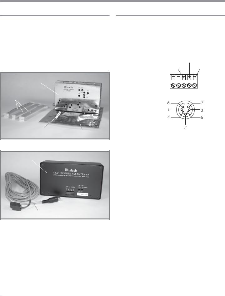
Connector Information
RAA1 Connectors
Connect the shield and two leads of a shielded 2 conductor cable to the supplied 5 Pin Terminal Connector Plug. Refer to the connection information on the top cover of the RAA1. If there is need to make-up a longer cable, use a two conductor shielded wire and the connectors below.
5 PinTerminal Connector |
|
Black |
|
1. N/C |
|
||
Red |
Green |
||
2. N/C |
|||
3. Red Wiire |
1 |
5 |
|
4. Black Wire |
|
|
|
5. Green Wire (Shield) |
|
|
7 Pin DIN Connector
1.Red Wire
2.Black Wire
3. N/C
4. N/C
5. N/C
6. Jumper from Pin 7
7. Green Wire (Shield) and Jumper to Pin 6
3

MX119, MX134 or MX135
Removing Covers
1. Remove ALL connecting cables from the Rear Panel of
the MX119, MX134 or MX135
A/V Controller.
2.Remove two screws from each side and two screws from the back that secure the Top Cover to the MX119, MX134 or MX135.
3.Lift off the Top Cover by grasping the rear sides of the top cover and lifting up and away from the MX119, MX134 or MX135.
4.Remove the Inside Connector Cover which is secured with two
Phillips Head Screws and is located on the Rear Panel. Refer to figures 3 and 4.
Note: Retain the two screws as they will be used later to install the AM/FM Tuner Module.
Installing the Cables and
Module |
|
|
Rear Panel |
||
5. Locate the three supplied |
||
Inside Cover |
||
ribbon cables from the |
||
|
||
shipping carton and at- |
|
|
tach the plug of the Six |
|
|
Conductor Ribbon Cable |
|
|
to the six pin Socket “J3” |
|
|
as indicated on the |
Data PC Board |
|
MX119, MX134 or |
||
|
||
MX135 Data PC Board. |
Connections |
|
Refer to figure 1 on page |
||
3 and figure 4 on this |
for Ribbon |
|
Cables |
||
page. |
||
|
||
Note: The six pin Cable |
J3 |
|
Plug and PC Board |
||
Socket are “keyed” |
J2 |
|
to attach only in one |
||
|
||
direction, do not |
J1 |
|
force it on |
||
|
||
backward. |
|
6. In a similar fashion, attach the plug of the Four
Conductor Ribbon Cable to the four pin PC Board Socket “J2” and the plug of the Seven Conductor Ribbon Cable to the seven pin Socket “J1”.
7.Relocate the free ends of the previously installed cables and rotate them over the top and to the right of the attached cable ends. Refer to figure 5.
8.Locate the AM/FM Tuner Module in the anti-static bag.
There is a TM1 Serial Number Label attached to the outside of the bag. Refer to figure 1. Remove the label from the bag and attached it to the Rear Panel of the MX119, MX134 or MX135 below the chassis opening labeled RAA1 AM ANT (DIN Connector). Refer to figure 6.
9. Remove the AM/FM Tuner Module from the anti-static bag.
Refer to figure 1. 10. Orient the Module so
the “F” Connector, that is at the bottom of the Module, will fit through the lower opening of the MX119, MX134 or MX135 Rear Panel (the cover was previously removed in Step 4) and the three PC Board Connectors are facing up. Refer to figures 5 and 6.
11. Secure the Module to the MX119, MX134 or MX135 Rear Panel with the two Phillips Head Screws that were previously removed from the
J4
J5
J3
Cables from Data PC Board
AM/FM
Tuner
Module
Figure 7
4
 Loading...