

Page 1

94799_LED-Unterbauleuchte_Model_A_Cover_CZ.indd 2 09.10.13 07:32
LED UNDER-CABINET LIGHTS
LED UNDER-CABINET LIGHTS
Assembly, operating and safety instructions
LED SVÍTIDLA POD SKŘÍNKU
Pokyny k montáži, obsluze a bezpečnostní pokyny
LED-UNTERBAULEUCHTEN
Montage-, Bedienungs- und Sicherheitshinweise
IAN 94799
Page 2
94799_LED-Unterbauleuchte_Model_A_Cover_CZ.indd 3 09.10.13 07:32
GB Assembly, operating and safety instructions Page 6
CZ Pokyny k montáži, obsluze a bezpečnostní pokyny Strana 13
DE / AT / CH Montage-, Bedienungs- und Sicherheitshinweise Seite 20
Page 3
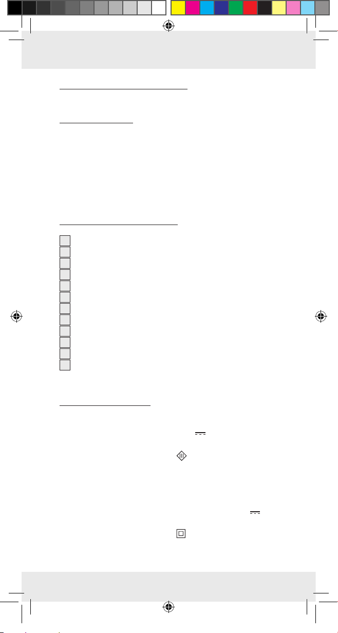
A
6
B
1
6 4
2
3454
94799_livx_LED-Unterbauleuchten_Model_A_Content_CZ.indd 3 09.10.13 07:39
78
3
Page 4
C
9
D
10 mm
Ø 12 mm
10
ø 2 mm
8
max. 70 cm
10 mm
Ø 12 mm
ø 2 mm
8
94799_livx_LED-Unterbauleuchten_Model_A_Content_CZ.indd 4 09.10.13 07:39
11
4
Page 5
E
9
1 2 3
ø 12 mm ø 12 mm
F
6
4
6
12
94799_livx_LED-Unterbauleuchten_Model_A_Content_CZ.indd 5 09.10.13 07:39
5
Page 6

Proper Use.............................................. Page 7
Description of parts ............................ Page 7
Technical Data ....................................... Page 7
Scope of Delivery ................................ Page 8
General safety instructions ............. Page 8
Before assembly .................................. Page 9
Installation ............................................. Page 9
Use ............................................................. Page 10
Cleaning and care ............................... Page 11
Disposal ................................................... Page 11
Guarantee .............................................. Page 11
94799_livx_LED-Unterbauleuchten_Model_A_Content_CZ.indd 6 09.10.13 07:39
6 GB
Page 7
LED Under-cabinet lights
Q
Proper Use
This under cabinet light is designed for illuminating work surfaces underneath wall units. This light is solely suitable for use
in dry, closed indoor spaces. This product is intended for use
in private, domestic environments only and not for commercial
purposes.
Q
Description of parts
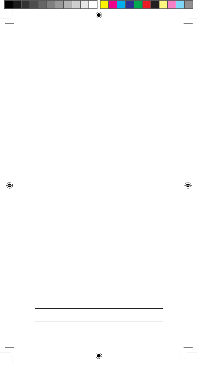
1
Low voltage connector
2
LED driver
3
European plug
4
LED spotlight
5
Motion sensor
6
Installation frame
7
Mounting bracket
8
Fastening hole
9
Cable bushing
10
Screws (ø 4 x 12 mm)
11
Slot of the mounting bracket
12
Screws (ø 3 x 11 mm)
94799_livx_LED-Unterbauleuchten_Model_A_Content_CZ.indd 7 09.10.13 07:39
Q
Technical Data
Under cabinet lights
Operating voltage: 24 V
Protection category:
Motion sensor range: approx. 8 cm
LED driver (model no. SB-GTWK6B)
Primary voltage: 230 V ~ 50 Hz, max. 7.3 W
Secondary voltage: max. 300 mA, 24 V
Maximum area temperature: 35 °C
Protection category:
, 2 x 3.1 W
(LEDs non replaceable)
7 GB
Page 8
Q
Scope of Delivery
2 installation frames (one with motion detector)
2 LED spotlights (already installed)
2 screws to install the installation frames
2 screws to install the LED drivers
1 LED driver with a European plug and low voltage connector
1 set of instructions for assembly and use
General safety instructions
BEFORE USING THIS PRODUCT; PLEASE FAMILIARISE
YOURSELF WITH ALL OF THE SAFETY INFORMATION
AND INSTRUCTIONS FOR USE! WHEN PASSING THIS
PRODUCT ON TO OTHERS; PLEASE ALSO INCLUDE ALL
OF THE DOCUMENTS!
DANGER TO LIFE AND
RISK OF ACCIDENTS FOR INFANTS AND
CHILDREN! Never leave children unattended
with the packaging material. The packaging material presents a danger of suffocation. Children frequently underestimate the dangers. Please keep children away from the
device at all times.
This appliance may be used by children age 8 years and
up, as well as by persons with reduced physical, sensory or
mental capacities, or lacking experience and / or knowledge,
so long as they are supervised or instructed in the safe use
of the appliance and understand the associated risks.
Children should not be allowed to play with the appliance.
Cleaning and user maintenance should not be performed
by children without supervision.
94799_livx_LED-Unterbauleuchten_Model_A_Content_CZ.indd 8 09.10.13 07:39
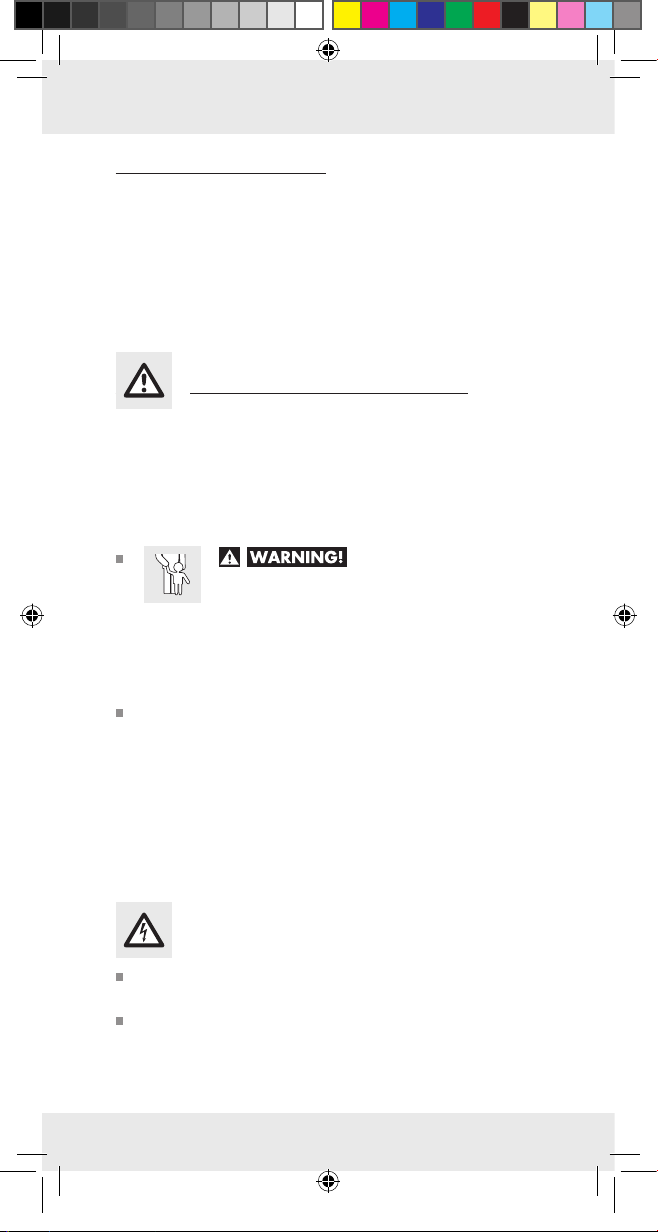
Danger to life by electric shock
Always check lamp for damage before connecting it to the
mains. Never use the light if it shows any signs of damage.
For the prevention of hazards, a damaged cable of this
lamp may only be exchanged by the manufacturer, his
service representative or by an equally qualified specialist!
8 GB
Page 9
Before assembly, ensure that the available mains voltage
corresponds to the operating voltage necessary for the light
(230 V ∼ 50 Hz). Otherwise do not install the light bulb.
Only use the under cabinet light set with the included LED
driver, model SB-GTWK6B.
Q
Before assembly
To start with, determine the installation location of the
under cabinet lights.
Then familiarise yourself with the installation and operation
instructions prior to assembly.
The underside of wall units and shelves made from wood
or chipboard are suitable for installation. The installation
6
frames
of the LED spotlights 4 must be installed with
the light pointing down and the flat side right up to the
wall. Please check before installing whether the included
screws are suitable for your wall unit or shelf.
All of the components of this light set must be installed
where they are protected from water and moisture.
The lights and LED driver 2 may not be covered by heat
insulating material. Otherwise there is the risk of overheating.
Ensure that the installation location gives the LED driver
sufficient ventilation. The area temperature of the LED driver
should never exceed 35°C.
To guarantee the flawless functioning of the motion sensor
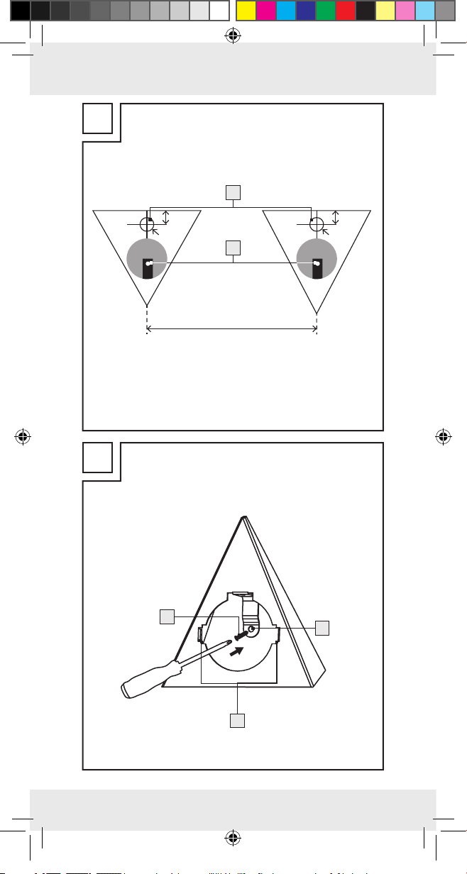
5
it must be installed at least 25 cm way from glossy
surfaces.
Ensure that the both installation frames for the LED spot-
lights are installed no further than 70 cm apart due to the
length of the connector cable.
Note that the next plug must be reached with the LED driver‘s cable (Length 150 cm). The length of the cable from
the LED driver to the first LED spotlight is 100 cm.
94799_livx_LED-Unterbauleuchten_Model_A_Content_CZ.indd 9 09.10.13 07:39
Q
Installation
Note: you will need an electric drill for the installation.
CAUTION! RISK OF INJURY! Please refer to the operating
instructions of your electric drill.
9 GB
Page 10

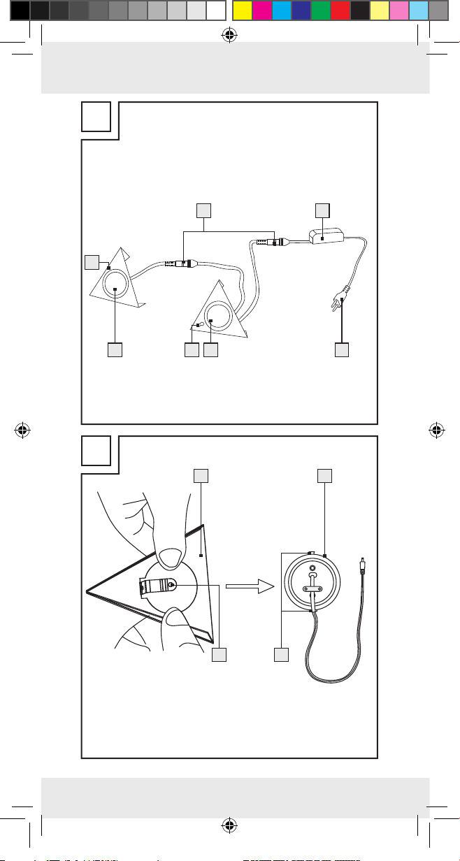
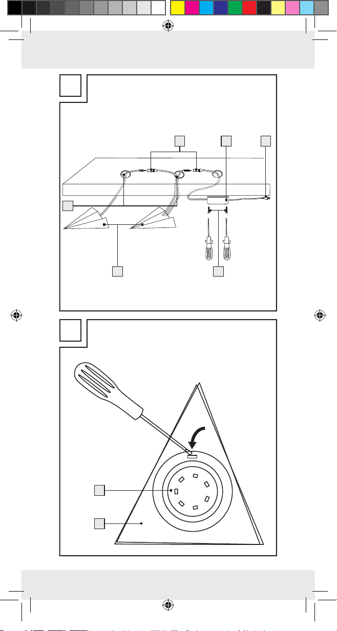
First remove the LED spotlights 4 from the installation
6
frames
by pushing on the back of the LED spotlights
(fig. B).
Note: If the installation frames are already installed, you
can lever the LED spotlight out from the front with a slot
screwdriver (Size: e.g 1.0 x 5.5 mm). Put the screwdriver
in the square notch on the rim of the LED spotlight (fig. F).
Hold both of the installation frames on the desired installa-
tion location and mark the fastening hole
8
on the surface
of the location. The angle must be bent down. Drill a hole
in the marked area with a 2 mm drill bit (fig C).
Please drill the cable bushing 9 according to fig. E with
a circumference of 12 mm.
Please secure both installation screws with the screws pro-
10
vided
(fig. D).
Lead the LED spotlight‘s cables through the cable bushing
(fig. E) and secure the LED spotlights
6
frames
. Be aware that the mounting brackets 7 for
4
in the installation
the spotlights can intervene in the slot of the mounting
11
bracket
(fig B).
Hold the LED driver to the desired installation location and
mark the fastening holes. Drill a hole in the marked area
with a 2 mm drill bit (fig E).
Install the LED driver 2 with the screws 12 included (fig. E).
Lay the cable. Ensure that the cable is laid so that is it pro-
tected against mechanical charging from external influences: Lay the cable, for example, in a conduit or
protected behind a ledge.
Connect all low voltage connectors 1 (fig. A, E).
Plug the European plug 3 into the socket.
94799_livx_LED-Unterbauleuchten_Model_A_Content_CZ.indd 10 09.10.13 07:39
Your under cabinet light is now ready for operation.
Q
Use
With the motion sensor 5 you can turn the under cabinet
light set on and off without making contact.
Move your hand at a distance of some 8 cm underneath
the sensor. The light switches on or off.
10 GB
Page 11

This function can be impaired by reflective objects near
the motion sensor.
Q
Cleaning and care
Unplug the light from the mains socket and let it cool down at
least 10 minutes.
Never immerse the product in water or other liquids. The
product may otherwise be damaged.
Clean the spotlight with a lint-free, slightly moist cloth and
mild cleaning agent.
The LED spotlights can be levered out of the installation
6
frames
with a slot screwdriver (Size: e.g. 1.0 x 5.5 mm).
Put the screwdriver in the square notch on the rim of the
LED spotlight.
Q
Disposal
The packaging is made of environmentally friendly
materials, which may be disposed of through your
local recycling facilities.
Contact your municipal authorities for details on
how to dispose of your worn-out product.
94799_livx_LED-Unterbauleuchten_Model_A_Content_CZ.indd 11 09.10.13 07:39
Q
Guarantee
The product has been manufactured according to strict quality
guidelines and meticulously examined before delivery. In the
event of product defects, you have legal rights against the
retailer of this product. Your statutory rights are not limited in
any way by our warranty detailed below.
This device is covered by a 3-year warranty from the date of
purchase. The warranty period begins on the date of purchase.
Please retain the original receipt safely. This document is required as your proof of purchase.
11 GB
Page 12

Should this device show any fault in materials or manufacture
within three years from date of purchase, it will be repaired or
replaced - at our choice - by us free of charge. This warranty
becomes void if the device has been damaged or improperly
used or maintained.
The warranty applies to faults in material or manufacture. This
guarantee does not apply to product parts which are subject
to normal wear and tear (e.g. batteries) and can be regarded
as wearing parts, or for damage to breakable parts, e.g., switch,
rechargeable batteries, or parts which are made of glass.
EMC
94799_livx_LED-Unterbauleuchten_Model_A_Content_CZ.indd 12 09.10.13 07:39
12 GB
Page 13

Použití ke stanovenému účelu ..........Strana 14
Popis dílů .............................................................Strana 14
Technické údaje .............................................Strana 14
Rozsah dodávky ...........................................Strana 15
Všeobecná bezpečnostní
upozornění ........................................................Strana 15
Před montáží ....................................................Strana 16
Montáž ..................................................................Strana 16
Obsluha ................................................................Strana 17
Čistění a ošetřování ....................................Strana 18
Odstranění do odpadu ............................Strana 18
Záruka ...................................................................Strana 18
94799_livx_LED-Unterbauleuchten_Model_A_Content_CZ.indd 13 09.10.13 07:39
13 CZ
Page 14

LED svítidla pod skřínku
Q
Použití ke stanovenému účelu
Toto vestavné svítidlo je určené k osvětlení pracovní plochy pod
závěsnými skříňkami. Svítidlo je vhodné jen k použití ve vnitřních
prostorech, v suchých a uzavřených místnostech. Výrobek je
určen pouze pro privátní použití v domácnosti, není vhodný
pro komerční účely.
Q
Popis dílů
1
Nízkonapěťová spojka
2
Řídící díl pro LED
3
Zástrčka
4
Bodové světlo s LED
5
Pohybový senzor
6
Montážní rámeček
7
Upevňovací sponka
8
Otvor na připevnění
9
Otvory pro zavedení vodičů
10
Šrouby (ø 4 x 12 mm)
11
Úchyty pro spony
12
Šrouby (ø 3 x 11 mm)
94799_livx_LED-Unterbauleuchten_Model_A_Content_CZ.indd 14 09.10.13 07:39
Q
Technické údaje
Vestavná svítidla
Provozní napětí: 24 V
Třída ochrany:
Dosah pohybového senzoru: cca 8 cm
Řídící díl pro LED (model č. SB-GTWK6B)
Primární napětí: 230 V ~ 50 Hz, max.
Sekundární napětí: max. 300 mA, 24 V
Maximální teplota okolního prostředí: 35 °C
Třída ochrany:
14 CZ
, 2 x 3,1 W
(LED nelze vyměnit)
7,3 W
Page 15

Q
Rozsah dodávky
2 montážní rámečky (jeden s pohybovým senzorem)
2 LED bodová světla (již vestavěná)
2 šrouby pro montáž rámečků
2 šrouby pro montáž řídícího dílu LED
1 řídící díl pro LED se zástrčkou a nízkonapěťovými spojkami
1 návod kmontáži a obsluze
Všeobecná bezpečnostní
upozornění
PŘED PRVNÍM POUŽITÍM VÝROBKU SE SEZNAMTE SE
VŠEMI POKYNY K OBSLUZE A BEZPEČNOSTNÍMI UPOZORNĚNÍMI! PŘI PŘEDÁVÁNÍ VÝROBKU TŘETÍ OSOBĚ
PŘEDÁVEJTE SOUČASNĚ I VŠECHNY JEHO PODKLADY!
NEBEZPEČÍ OHROŽENÍ
ŽIVOTA A ZRANĚNÍ MALÝCH A VĚTŠÍCH DĚTÍ! Nenechávejte děti nikdy samotné
s obalovým materiálem. Hrozí jim nebezpečí udušení. Děti
nebezpečí často podceňují. Výrobek vždy chraňte před
dětmi.
Tento přístroj mohou používat děti starší než 8 let, osoby se
sníženými fyzickými, senzorickými nebo duševními schopnosti nebo s nedostatečnými zkušenostmi a znalostmi o
používání přístroje jen tehdy, jestliže byly poučeny o jeho
bezpečném používání a porozuměly možným ohrožením.
Děti si nesmí s přístrojem hrát. Děti nesmí provádět čištění
a údržbu bez dohledu.
94799_livx_LED-Unterbauleuchten_Model_A_Content_CZ.indd 15 09.10.13 07:39
Nebezpečí ohrožení života úrazem
elektrickým proudem
Před každým připojením na rozvod elektrického proudu
zkontrolujte svítidlo jestli není poškozené. Nikdy nepoužívejte svítidlo, pokud jste zjistili, že je poškozené.
Za účelem zabránění ohrožení smí poškozené vnější pružné
vedení tohoto svítidla vyměňovat výhradně výrobce, jeho
servisní zástupce nebo srovnatelný odborník!
15 CZ
Page 16

Před montáží se ujistěte, že se místní síťové napětí shoduje
sprovozním napětím svítidla (230 V ~ 50 Hz). V opačném
případě lampu nepřipojujte.
Používejte soupravu vestavných svítidel jen s dodaným
řídícím dílem pro LED, model SB-GTWK6B.
Q
Před montáží
Zvolte umístění vestavných svítidel.
Nejdříve si přečtěte pokyny k montáži a obsluze svítidla.
Předpokládá se montáž na spodní stranu dřevěných nebo
dřevotřískových zavěšených skříněk i regálů. Montážní
rámečky
6
LED bodových světel 4 se musí montovat
plochou stranou ke stěně. Před montáží se přesvědčte, že
jsou přiložené šrouby vhodné k přišroubování svítidel na
Vaší zavěšenou skříňku nebo regál.
Všechny díly této soupravy svítidel musí být namontované
tak, aby byly chráněné před vlhkostí a mokrem.
Svítidla a řídící díl pro LED 2 nesmí být přikryté tepelně
izolujícím materiálem. V opačném případě hrozí nebezpečí
přehřátí.
Při volbě umístění a montáže řídícího dílu pro LED dbejte
na dostatečné větrání. Teplota prostředí, ve kterém je
umístěný řídící díl pro LED, nesmí překročit 35 °C.
Pro bezvadnou funkci pohybového senzoru 5 je důležité,
aby byl umístěn nejméně 25 cm od lesklých povrchů.
Dbejte na to, že je možné montovat rámečky bodových
světel v odstupu maximálně 70 cm, aby je bylo možné
spojit kabelem. Rovněž dejte pozor, aby dosáhl přívodní
kabel řídícího dílu pro LED o délce 150 cm k zásuvce s
elektrickým proudem. Délka kabelu od řídícího dílu LED k
prvnímu bodovému světlu činí 100 cm.
94799_livx_LED-Unterbauleuchten_Model_A_Content_CZ.indd 16 09.10.13 07:39
Q
Montáž
Upozornění: Kmontáži budete potřebovat vrtačku.
POZOR! NEBEZPEČÍ ZRANĚNÍ! Použijte ktomu návod k
obsluze vaší vrtačky.
16 CZ
Page 17

Nejdříve vyjmněte LED bodové světlo 4 z montážního
rámečku
6
zatlačením na jeho zadní stranu (obr. B).
Poznámka: Jestliže je montážní rámeček již namonto-
vaný, můžete z něho bodové světlo vpředu vypáčit plochým
šroubovákem (o velikosti: např. 1,0 x 5,5 mm). K tomu nastrčte šroubovák do obdélníkového vybrání na okraji LED
bodového světla (obr. F).
Přidržte postupně oba montážní rámečky na vyhlédnutých
místech a označte si polohy k vyvrtání otvorů
8
. Úhel
musí směřovat směrem dolů. Vyvrtejte vrtákem o průměru
2 mm otvor na označeném místě (obr. C).
Vyvrtejte podle obrázku E, vrtákem o průměru 12 mm,
průchody pro kabely
9
.
Přišroubujte oba montážní rámečky přiloženými šrouby
10
(obr. D).
Protáhněte přívody bodových světel průchody (obr. E) a
připevněte LED bodová světla
na to, aby zapadly upevňovací sponky
světel do příslušných vybrání
4
do rámečků 6. Dbejte
7
bodových
11
(obr. B).
Přidržte řídící díl pro LED na vyhlédnutém místě a označte
si polohy budoucích otvorů pro připevnění. Vyvrtejte vrtákem o průměru 2 mm otvory na označených místech (obr. E).
Přišroubujte řídící díl pro LED 2 přiloženými šrouby 12
(obr. E).
Zaveďte kabely. Dávejte pozor, aby byly zavedené kabely
chráněné před mechanickým zatížením: umístěte je například do kabelového kanálu nebo pod lištu.
Propojte kabely všemi nízkonapěťovými spojkami 1
(obr. A, E).
Zastrčte zástrčku 3 do zásuvky přívodu elektrického
proudu.
94799_livx_LED-Unterbauleuchten_Model_A_Content_CZ.indd 17 09.10.13 07:39
Vaše vestavná svítidla jsou nyní připravena kprovozu.
Q
Obsluha
Pohybovým senzorem 5 můžete soupravu vestavných svítidel
bez dotyku zapínat a vypínat.
Pohybujte rukou asi 8 cm pod senzorem. Svítidla se zapnou
nebo vypnou.
17 CZ
Page 18

Tato funkce může být rušena předměty, které se v blízkosti
senzoru zrcadlí.
Q
Čistění a ošetřování
Vytáhněte zástrčku ze zásuvky a nechte svítidlo nejméně
10 minut vychladnout.
Neponořujte výrobek v žádném případě do vody nebo
do jiných tekutin. V opačném případě může dojít k jeho
poškození.
Čistěte svítidlo mírně navlhčenou tkaninou, která nepouští
vlákna a jemným čisticím prostředkem.
Bodová světla můžete vypáčit z rámečků 6 plochým
šroubovákem (např. o velikosti 1,0 x 5,5 mm). K tomu nastrčte šroubovák do obdélníkového vybrání na okraji LED
bodového světla.
Q
Odstranění do odpadu
Balení je vyrobeno z ekologických materiálů, které
můžete odstranit do odpadu v místních sběrnách
tříděného odpadu.
O možnostech likvidace vysloužilých zařízení se
informujte u správy vaší obce nebo města.
94799_livx_LED-Unterbauleuchten_Model_A_Content_CZ.indd 18 09.10.13 07:39
Q
Záruka
Výrobek byl vyroben snejvyšší pečlivostí podle přísných kvalitativních směrnic a před odesláním prošel výstupní kontrolou.
V případě závad máte možnost uplatnění zákonných práv
vůči prodejci. Vaše práva ze zákona nejsou omezena naší
níže uvedenou zárukou.
Na tento přístroj platí tříletá záruka od data zakoupení. Záruční
lhůta začíná od data zakoupení. Uschovejte si dobře originál
pokladní stvrzenky. Tuto stvrzenku budete potřebovat jako
doklad o zakoupení.
18 CZ
Page 19

Pokud se do tří let od data zakoupení tohoto výrobku vyskytne
vada materiálu nebo výrobní vada, výrobek Vám – dle našeho rozhodnutí – bezplatně opravíme nebo vyměníme. Tato
záruka zaniká, jestliže se výrobek poškodí, neodborně použil
nebo neobdržel pravidelnou údržbu.
Záruka platí na vady materiálu a výrobní vady. Tato záruka se
nevztahuje na díly výrobku podléhající opotřebení (např. na
baterie), dále na poškození křehkých, choulostivých dílů, např.
vypínačů, akumulátorů nebo dílů zhotovených ze skla.
EMC
94799_livx_LED-Unterbauleuchten_Model_A_Content_CZ.indd 19 09.10.13 07:39
19 CZ
Page 20

Bestimmungsgemäße
Verwendung ...................................................... Seite 21
Teilebeschreibung .......................................... Seite 21
Technische Daten ............................................ Seite 21
Lieferumfang ...................................................... Seite 22
Allgemeine Sicherheitshinweise ........ Seite 22
Vor der Montage ............................................ Seite 23
Montage ................................................................. Seite 24
Bedienung ............................................................ Seite 25
Reinigung und Pflege .................................. Seite 25
Entsorgung ........................................................... Seite 26
Garantie ................................................................. Seite 26
94799_livx_LED-Unterbauleuchten_Model_A_Content_CZ.indd 20 09.10.13 07:39
20 DE/AT/CH
Page 21

LED-Unterbauleuchten
Q
Bestimmungsgemäße Verwendung
Diese Unterbauleuchte ist zur Beleuchtung von Arbeitsflächen
unterhalb von Hängeschränken vorgesehen. Die Leuchte ist
ausschließlich für den Betrieb im Innenbereich, in trockenen
und geschlossenen Räumen geeignet. Das Produkt ist nur für
den Einsatz in privaten Haushalten und nicht für den kommerziellen Gebrauch vorgesehen.
Q
Teilebeschreibung
1
Kleinspannungs-Steckverbinder
2
LED-Treiber
3
Eurostecker
4
LED-Spot
5
Bewegungssensor
6
Montagerahmen
7
Befestigungsklammer
8
Befestigungsloch
9
Leitungsdurchführung
10
Schrauben (ø 4 x 12 mm)
11
Aufnahme der Befestigungsklammer
12
Schrauben (ø 3 x 11 mm)
94799_livx_LED-Unterbauleuchten_Model_A_Content_CZ.indd 21 09.10.13 07:39
Q
Technische Daten
Unterbauleuchten
Betriebsspannung: 24 V
, 2 x 3,1 W
(LEDs nicht austauschbar)
Schutzklasse:
Reichweite Bewegungssensor: ca. 8 cm
LED-Treiber (Modell Nr. SB-GTWK6B)
Spannung primär: 230 V ~ 50 Hz, max. 7,3 W
Spannung sekundär: max. 300 mA, 24 V
Maximale Umgebungstemperatur: 35 °C
Schutzklasse:
21 DE/AT/CH
Page 22

Q
Lieferumfang
2 Montagerahmen (einer mit Bewegungsmelder)
2 LED-Spots (bereits eingebaut)
2 Schrauben zur Montage der Montagerahmen
2 Schrauben zur Montage des LED-Treibers
1 LED-Treiber mit Eurostecker und Kleinspannungssteckverbindern
1 Montage- und Bedienungsanleitung
Allgemeine
Sicherheitshinweise
MACHEN SIE SICH VOR DER ERSTEN BENUTZUNG DES
PRODUKTS MIT ALLEN BEDIEN- UND SICHERHEITSHINWEISEN VERTRAUT! HÄNDIGEN SIE ALLE UNTERLAGEN
BEI WEITERGABE DES PRODUKTS AN DRITTE EBENFALLS
MIT AUS!
LEBENS- UND UN-
FALLGEFAHR FÜR KLEINKINDER UND
KINDER! Lassen Sie Kinder niemals unbeauf-
sichtigt mit dem Verpackungsmaterial. Es besteht Erstickungsgefahr durch Verpackungsmaterial. Kinder unterschätzen
häufig die Gefahren. Halten Sie Kinder stets vom Produkt
fern.
Dieses Gerät kann von Kindern ab 8 Jahren und darüber
sowie von Personen mit verringerten physischen, sensorischen
oder mentalen Fähigkeiten oder Mangel an Erfahrung
und Wissen benutzt werden, wenn sie beaufsichtigt oder
bezüglich des sicheren Gebrauchs des Gerätes unterwiesen
wurden und die daraus resultierenden Gefahren verstehen.
Kinder dürfen nicht mit dem Gerät spielen. Reinigung und
Benutzerwartung dürfen nicht von Kindern ohne Beaufsichtigung durchgeführt werden.
94799_livx_LED-Unterbauleuchten_Model_A_Content_CZ.indd 22 09.10.13 07:39
Lebensgefahr durch
elektrischen Schlag
Überprüfen Sie vor jedem Netzanschluss die Leuchte auf
etwaige Beschädigungen. Benutzen Sie Ihre Leuchte niemals, wenn Sie irgendwelche Beschädigungen feststellen.
22 DE/AT/CH
22 DE/AT/CH
Page 23

Zur Vermeidung von Gefährdungen darf eine beschädigte
äußere Leitung dieser Leuchte ausschließlich vom Hersteller,
seinem Servicevertreter oder einer vergleichbaren Fachkraft ausgetauscht werden.
Vergewissern Sie sich vor der Montage, dass die vorhandene
Netzspannung mit der benötigten Betriebsspannung der
Leuchte übereinstimmt (230 V ~ 50 Hz). Montieren Sie die
Leuchte nicht, wenn dies nicht der Fall ist.
Verwenden Sie das Unterbauleuchten-Set ausschließlich
mit dem mitgeliefertem LED-Treiber, Modell SB-GTWK6B.
Q
Vor der Montage
Bestimmen Sie zunächst den Montageort der Unterbau-
leuchten.
Machen Sie sich hierzu zunächst mit den Montage- und
Bedienhinweisen der Leuchte vertraut.
Zur Montage ist die Unterseite von Hängeschränken oder
Hängeregalen aus Holz oder Spanplatte vorgesehen. Die
Montagerahmen
6
der LED-Spots 4 müssen mit der
Strahlrichtung nach unten und der flachen Seite zur Wand
hin montiert werden. Vergewissern Sie sich vor der Montage,
ob die beiliegenden Schrauben zur Befestigung an Ihrem
Hängeschrank oder Hängeregal geeignet sind.
Alle Komponenten dieses Leuchten-Sets müssen vor Feuch-
tigkeit und Nässe geschützt montiert werden.
Die Leuchten und der LED-Treiber 2 dürfen nicht durch
wärmedämmende Materialien abgedeckt werden. Andernfalls besteht Überhitzungsgefahr.
Achten Sie bei der Wahl des Montageorts des LED-Treibers
auf eine ausreichende Belüftung. Die Umgebungstemperatur
des LED-Treibers darf 35 °C nicht überschreiten.
Um eine einwandfreie Funktion des Bewegungssensors 5 zu
gewährleisten, muss dieser mindestens 25 cm von glänzenden Oberflächen entfernt montiert werden.
Beachten Sie, dass die beiden Montagerahmen der LED-
Spots aufgrund der Länge der Verbindungsleitung maximal
70 cm voneinander entfernt montiert werden können.
Beachten Sie auch, dass die nächste Steckdose mit der
Zuleitung des LED-Treibers (Länge 150 cm) erreichbar sein
94799_livx_LED-Unterbauleuchten_Model_A_Content_CZ.indd 23 09.10.13 07:39
23 DE/AT/CH
23 DE/AT/CH
Page 24

muss. Die Länge der Leitung vom LED-Treiber bis zum ersten
LED-Spot beträgt 100 cm.
Q
Montage
Hinweis: Für die Montage benötigen Sie eine Bohrmaschine.
VORSICHT! VERLETZUNGSGEFAHR! Ziehen Sie die
Bedienungsanleitung Ihrer Bohrmaschine hinzu.
Entfernen Sie zunächst die LED-Spots 4 aus den Montage-
rahmen
6
, indem Sie auf die Rückseite der LED-Spots
drücken (Abb. B).
Hinweis: Ist der Montagerahmen bereits montiert, können
Sie den LED-Spot mithilfe eines Schlitzschraubendrehers
(Größe: z. B. 1,0 x 5,5 mm) von vorne aus dem Montagerahmen hebeln. Stecken Sie den Schraubendreher hierzu
in die rechteckige Aussparung am Rand des LED-Spots
(Abb. F).
Halten Sie die beiden Montagerahmen an die vorgesehe-
nen Montageorte und markieren Sie das Befestigungsloch
8
des Montagerahmens auf dem Montageuntergrund.
Der Winkel muss nach unten gebogen werden. Bohren Sie
die so markierte Stelle mit einem 2-mm-Bohrer vor (Abb. C).
Bohren Sie gemäß Abb. E die Leitungsdurchführungen 9
mit einem Durchmesser von 12 mm.
Befestigen Sie die beiden Montagerahmen mit den beilie-
genden Schrauben
10
(Abb. D).
Führen Sie die Zuleitungen der LED-Spots durch die Leitungs-
durchführungen (Abb. E) und befestigen Sie die LED-Spots
4
in den Montagerahmen 6. Achten Sie darauf, dass
die Befestigungsklammern
der Befestigungsklammern
7
der Spots in die Aufnahme
11
eingreifen können (Abb. B).
Halten Sie den LED-Treiber an die vorgesehene Montage-
stelle und markieren Sie die Befestigungslöcher. Bohren
Sie die so markierten Stellen mit einem 2-mm-Bohrer vor
(Abb. E).
Montieren Sie den LED-Treiber 2 mit den beiliegenden
Schrauben
12
(Abb. E).
Verlegen Sie die Leitungen. Achten Sie darauf, dass die
Leitungen gegen eine mechanische Belastung durch äußere
Einflüsse geschützt verlegt werden: Verlegen Sie die Leitungen
94799_livx_LED-Unterbauleuchten_Model_A_Content_CZ.indd 24 09.10.13 07:39
24 DE/AT/CH
24 DE/AT/CH
Page 25

beispielsweise in einem Kabelkanal oder geschützt hinter
einer Leiste.
Verbinden Sie alle Kleinspannungs-Steckverbinder 1
(Abb. A, E).
Stecken Sie den Eurostecker 3 in die Steckdose.
Ihre Unterbauleuchte ist nun betriebsbereit.
Q
Bedienung
Sie können am Bewegungssensor 5 das Unterbauleuchten-Set
berührungslos ein- und ausschalten.
Bewegen Sie Ihre Hand in etwa 8 cm Abstand unter dem
Sensor. Die Leuchte schaltet sich ein bzw. aus.
Diese Funktion kann durch spiegelnde Gegenstände in
der Nähe des Bewegungssensors beeinträchtigt werden.
Q
Reinigung und Pflege
Entfernen Sie die Leuchte aus der Steckdose und lassen Sie
sie mindestens 10 Minuten lang abkühlen.
Tauchen Sie das Produkt niemals in Wasser oder in andere
Flüssigkeiten. Andernfalls kann das Produkt beschädigt
werden.
Reinigen Sie die Leuchte mit einem fusselfreien, leicht
angefeuchteten Tuch und mildem Reinigungsmittel.
Die LED-Spots können mithilfe eines Schlitzschraubendrehers
(Größe: z. B. 1,0 x 5,5 mm) aus dem Montagerahmen
6
gehebelt werden. Stecken Sie den Schraubendreher hierzu
in die rechteckige Aussparung am Rand des LED-Spots.
94799_livx_LED-Unterbauleuchten_Model_A_Content_CZ.indd 25 09.10.13 07:39
25 DE/AT/CH
25 DE/AT/CH
Page 26

Q
Entsorgung
Die Verpackung besteht aus umweltfreundlichen
Materialien, die Sie über die örtlichen Recyclingstellen entsorgen können.
Möglichkeiten zur Entsorgung des ausgedienten
Produkts erfahren Sie bei Ihrer Gemeinde- oder
Stadtverwaltung.
Q
Garantie
Das Produkt wurde nach strengen Qualitätsrichtlinien sorgfältig
produziert und vor Anlieferung gewissenhaft geprüft. Im Falle
von Mängeln dieses Produkts stehen Ihnen gegen den Verkäufer des Produkts gesetzliche Rechte zu. Diese gesetzlichen
Rechte werden durch unsere im Folgenden dargestellte Garantie nicht eingeschränkt.
Sie erhalten auf dieses Gerät 3 Jahre Garantie ab Kaufdatum.
Die Garantiefrist beginnt mit dem Kaufdatum. Bitte bewahren Sie
den Original Kassenbon gut auf. Diese Unterlage wird als
Nachweis für den Kauf benötigt.
Tritt innerhalb von drei Jahren ab dem Kaufdatum dieses Produkts ein Material- oder Fabrikationsfehler auf, wird das Produkt von uns – nach unserer Wahl – für Sie kostenlos repariert
oder ersetzt. Diese Garantie verfällt, wenn das Produkt beschädigt, nicht sachgemäß benutzt oder gewartet wurde.
94799_livx_LED-Unterbauleuchten_Model_A_Content_CZ.indd 26 09.10.13 07:39
Die Garantieleistung gilt für Material- oder Fabrikationsfehler.
Diese Garantie erstreckt sich nicht auf Produktteile, die normaler Abnutzung ausgesetzt sind (z. B. Batterien) und daher als
Verschleißteile angesehen werden können oder für Beschädigungen an zerbrechlichen Teilen, z. B. Schalter, Akkus oder
die aus Glas gefertigt sind.
EMC
26 DE/AT/CH
26 DE/AT/CH
Page 27

OWIM GmbH & Co. KG
Stiftsbergstraße 1
D-74167 Neckarsulm
Modell Nr.: Z31791A
Version: 09 / 2013
Last Information Update
Stav informací · Stand der Informationen:
10 / 2013 · Ident.-No.: Z31791A102013-CZ
94799_LED-Unterbauleuchte_Model_A_Cover_CZ.indd 1 09.10.13 07:32
IAN 94799
4
 Loading...