


STB-5500
HD Commercial Interface Set-top Box
Commercial Mode Setup Guide
Interactive Pro:Centric ® •
Functionality
RF or IP Content Delivery •
EXPERIENCED INSTALLER
EZ-Manager Wizard pages 17 – 26
Custom Master STB Setup pages 42 – 44
Cloning Procedures pages 45 – 51
|
|
© Copyright 2017 LG Electronics U.S.A., Inc. |
P/N: 206-4310 (Rev A) |
|
|
For Customer Support/Service, please call:
1-888-865-3026
The latest product information and documentation is available online at:
www.lg.com/us/business
MODEL and SERIAL NUMBER
The model and serial numbers of this STB are located on the back of the cabinet. For future reference, LG suggests that you record those numbers here:
Model No._________________ Serial No._______________
WARNING
RISK OF ELECTRIC SHOCK
DO NOT OPEN
WARNING:
TO REDUCE THE RISK OF ELECTRIC SHOCK DO NOT REMOVE COVER (OR BACK). NO USERSERVICEABLE PARTS INSIDE. REFER TO QUALIFIED SERVICE PERSONNEL.
The lightning flash with arrowhead symbol, within an equilateral triangle, is intended to alert the user to the presence of uninsulated “dangerous voltage” within the product’s enclosure that may be of sufficient magnitude to constitute a risk of electric shock to persons.
The exclamation point within an equilateral triangle is intended to alert the user to the presence of important operating and maintenance (servicing) instructions in the literature accompanying the appliance.
WARNING:
TO PREVENT FIRE OR SHOCK HAZARDS, DO NOT EXPOSE THIS PRODUCT TO RAIN OR MOISTURE.
WARNING:
This product contains chemicals known to the State of California to cause cancer and birth defects or other reproductive harm. Wash hands after handling.
NOTE TO CABLE/TV INSTALLER:
This reminder is provided to call the cable TV system installer’s attention to Article 820-40 of the National Electrical Code (U.S.A.). The code provides guidelines for proper grounding and, in particular, specifies that the cable ground shall be connected to the grounding system of the building, as close to the point of the cable entry as practical.
REGULATORY INFORMATION:
This equipment has been tested and found to comply with the limits for a Class B digital device, pursuant to Part 15 of the FCC Rules. These limits are designed to provide reasonable protection against harmful interference when the equipment is operated in a residential installation. This equipment generates, uses and can radiate radio frequency energy and, if not installed and used in accordance with the instruction manual, may cause harmful interference to radio communications. However, there is no guarantee that interference will not occur in a particular installation. If this equipment does cause harmful interference to radio or television reception, which can be determined by turning the equipment off and on, the user is encouraged to try to correct the interference by one or more of the following measures:
•Reorient or relocate the receiving antenna.
•Increase the separation between the equipment and receiver.
•Connect the equipment to an outlet on a circuit different from that to which the receiver is connected.
•Consult the dealer or an experienced radio/TV technician for help.
CAUTION:
Do not attempt to modify this product in any way without written authorization from LG Electronics U.S.A., Inc. Unauthorized modification could void the user’s authority to operate this product.
COMPLIANCE:
The responsible party for this product’s compliance is: LG Electronics U.S.A., Inc. 1000 Sylvan Avenue, Englewood Cliffs, NJ 07632, USA • Phone: 1-201-816-2000
Marketed and Distributed in the United States by LG Electronics U.S.A., Inc. 1000 Sylvan Avenue, Englewood Cliffs, NJ 07632
2 |
© Copyright 2017 LG Electronics U.S.A., Inc. |
206-4310 |

IMPORTANT SAFETY INSTRUCTIONS
1.Read these instructions.
2.Keep these instructions.
3.Heed all warnings.
4.Follow all instructions.
5.Do not use this apparatus near water.
6.Clean only with dry cloth.
7.Do not block any ventilation openings. Install in accordance with the manufacturer’s instructions.
8.Do not install near any heat sources, such as radiators, heat registers, stoves, or other apparatus (including amplifiers) that produce heat.
9.Do not defeat the safety purpose of the polarized or grounding-type plug. A polarized plug has two blades with one wider than the other. A grounding-type plug has two blades and a third grounding prong. The wide blade or the third prong are provided for your safety. If the provided plug does not fit into your outlet, consult an electrician for replacement of the obsolete outlet.
10.Protect the power cord from being walked on or pinched, particularly at plugs, convenience receptacles, and the point where it exits from the apparatus.
11.Only use attachments/accessories specified by the manufacturer.
12.Use only with the cart, stand, tripod, bracket, or table specified by the manufacturer or sold with the apparatus. When a cart is used, use caution when moving the cart/ apparatus combination in order to avoid injury from tip-over.
PORTABLE CART WARNING
13.Refer all servicing to qualified service personnel.
Servicing is required when the apparatus has been damaged in any way, such as power-supply cord or plug is damaged, liquid has been spilled or objects have fallen into the apparatus, the apparatus has been exposed to rain or moisture, does not operate normally, or has been dropped.
14.Never touch this apparatus or antenna during a thunder or lightning storm.
15.When mounting an STB on the wall, make sure that none of the electrical cabling bears any of the weight of the STB. Install in accordance with the manufacturer’s instructions.
16.Power Cord
Caution: Check the STB specifications in the Owner’s Manual to determine power requirements.
Periodically examine the cord of your appliance, and if its appearance indicates damage or deterioration, unplug it, discontinue use of the appliance, and have the cord replaced with an exact replacement part by an authorized servicer. Protect the power cord from physical or mechanical abuse, such as twisting, kinking, or pinching or being closed in a door or walked upon. Pay particular attention to plugs, wall outlets, and the point where the cord exits the appliance.
Do not use a damaged or loose power cord. Be sure to grasp the plug when unplugging the power cord. Do not pull on the power cord to unplug the STB.
Do not stick metal objects or any other conductive material into the power cord. Do not touch the end of the power cord while it is plugged in.
17.Overloading
Do not connect too many appliances to the same AC power outlet as this could result in fire or electric shock. Do not overload wall outlets. Overloaded wall outlets, loose or damaged wall outlets, extension cords, frayed power cords, or damaged or cracked wire insulation are dangerous. Any of these conditions could result in fire or electric shock.
18.Outdoor Use/Wet Location
Warning: To reduce the risk of fire or electrical
shock, do not expose this product to rain,
moisture or other liquids.
Do not touch the STB with wet hands. Do not install this product near flammable objects such as gasoline or candles or expose the STB to direct air conditioning.
Do not expose to dripping or splashing and do not place objects filled with liquids, such as vases, cups, etc., on or over the apparatus (e.g., on shelves above the unit).
19.Grounding
(Except for devices that are not grounded) Ensure that you connect the earth ground wire to prevent possible electric shock (i.e., an STB with a three-prong grounded AC plug must be connected to a three-prong grounded AC outlet). If grounding methods are not possible, have a qualified electrician install a separate circuit breaker. Do not try to ground the unit by connecting it to telephone wires, lightning rods, or gas pipes.
20.Disconnect Device
The power plug is the disconnecting device. The power plug must remain readily accessible.
As long as this unit is connected to the AC wall outlet, it is not disconnected from the AC power source even if the unit is turned off.
(Continued on next page)
206-4310 |
3 |

IMPORTANT SAFETY INSTRUCTIONS
(Continued from previous page)
21.Outdoor Antenna Grounding
If an outside antenna or cable system is connected to the product, follow the precautions below.
An outdoor antenna system should not be located in the vicinity of overhead power lines or other electric light or power circuits or where it can come into contact with such power lines or circuits as death or serious injury can occur.
Be sure the antenna system is grounded so as to provide some protection against voltage surges and built-up static charges.
Article 810 of the National Electrical Code (NEC) in the U.S.A. provides information with respect to proper grounding of the mast and supporting structure, grounding of the lead-in wire to an antenna-discharge unit, size of grounding conductors, location of antenna-discharge unit, connection to grounding electrodes, and requirements for the grounding electrode.
Antenna Grounding According to NEC, ANSI/NFPA 70
26.Keep the product away from direct sunlight.
27.Do not install this product on a wall if it could be exposed to oil or oil mist. This may damage the product and cause it to fall.
28.Do not allow an impact shock or any objects to fall into the product.
29.Do not touch the ventilation openings, as they may become hot while the STB is operating. This does not affect the performance of the product or cause defects in the product.
30.Do not use high voltage electrical equipment near the STB (e.g., a bug zapper). This may result in product malfunction.
Ground Clamp |
Antenna Lead in Wire |
|
|
|
Antenna Discharge Unit |
|
(NEC Section 810-20) |
|
Grounding Conductor |
Electric Service |
(NEC Section 810-21) |
|
|
Equipment |
Ground Clamps |
|
|
|
Power Service Grounding |
|
Electrode System (NEC |
|
Art 250, Part H) |
22.Cleaning
When cleaning, unplug the power cord and wipe gently with a soft cloth to prevent scratching. Do not spray water or other
liquids directly on the STB as electric shock may occur. Do not clean with chemicals such as alcohol, thinners or benzene.
23.Transporting Product
Make sure the STB is turned Off and unplugged and that all cables have been removed. Do not press against or put stress on the STB.
24.Ventilation
Install the STB where there is proper ventilation. Do not install in a confined space such as a bookcase. Do not cover the STB with cloth or other materials (e.g., plastic) while it is plugged in. Do not install in excessively dusty places.
25.If you smell smoke or other odors coming from the STB or hear strange sounds, unplug the power cord, and contact an authorized service center.
4 |
206-4310 |

Table of Contents
Safety Warnings . . . . . . . . . . . . . . . . . 2 Important Safety Instructions . . . . . . . . . . . . . . . . . . . . . . 3 – 4 Table of Contents . . . . . . . . . . . . . . . . 5
STB-5500 Introduction / Setup Checklist . . . . . . 6 Introduction . . . . . . . . . . . . . . . . . . 6 Setup Checklist . . . . . . . . . . . . . . . . 6
STB-5500 Cabling Connections . . . . . . . . . 7 – 10 Before You Begin . . . . . . . . . . . . . . . . 7 Connect the STB to the Display Panel . . . . . . . 8 STB-5500 Cabling Diagram . . . . . . . . . . . 10
Commercial Mode Overview . . . . . . . . . 11 – 13 Pass-through Mode . . . . . . . . . . . . . . .11 FTG Mode . . . . . . . . . . . . . . . . . . 12 Determining the STB Operating Mode . . . . . . . . . . . . . . 13
Pro:Centric Operation . . . . . . . . . . . . 14 – 15 Pro:Centric Interactive Menu Features . . . . . . . 14 Pro:Centric Interactive Menu Navigation . . . . . . 14 Pro:Centric Setup . . . . . . . . . . . . . . . 15
Setting the Video Output Resolution . . . . . . . 16
EZ-Manager Wizard . . . . . . . . . . . . . 17 – 26 Before You Begin . . . . . . . . . . . . . . . 17 Initiate Configuration or Exit the EZ-Manager Wizard . 18 STB Configuration Options . . . . . . . . . . . 19 Zones and Room Number Assignments . . . . . . 19 Configure Pro:Centric Settings . . . . . . . . . . 21 USB Configuration . . . . . . . . . . . . . . . 25
Ez Download Utility . . . . . . . . . . . . . 27 – 30 Before You Begin . . . . . . . . . . . . . . . 27 Accessing and Using the Ez Download Utility . . . . 27 Installer Menu . . . . . . . . . . . . . . . 31 – 41 Accessing the Installer Menu . . . . . . . . . . . 31 Using the Installer Menu . . . . . . . . . . . . 32 Exiting the Installer Menu and Activating Settings . . . 32 Detailed Descriptions of Installer Menu Items . . . . 35
Custom Master STB Setup . . . . . . . . . . 42 – 44 Before You Begin . . . . . . . . . . . . . . . 42 Clonable STB Setup Menu Features . . . . . . . . 42 Custom Master STB Setup Procedure . . . . . . . 43 Cloning Procedures . . . . . . . . . . . . . 45 – 51
Exporting a Clone File . . . . . . . . . . . . . 45 Importing a Clone File . . . . . . . . . . . . . 47
FTG File Manager Utilities Overview . . . . . . 52 – 57 Creating an FTG Configuration File . . . . . . . . 52 FTG File Manager Main Screen . . . . . . . . . 54 FTG Channel Map Configuration Utility . . . . . . . 55 FTG Channel Map Editor . . . . . . . . . . . . 56 FTG Installer Menu Configuration Utility . . . . . . 57
IP Environment Setup . . . . . . . . . . . . 58 – 65 Accessing the IP Environment Menu . . . . . . . . 58 Network Configuration . . . . . . . . . . . . . 58 Pro:Centric Setup . . . . . . . . . . . . . . . 62 Media Share Setup . . . . . . . . . . . . . . 64 Pre-loaded Applications . . . . . . . . . . . . . 65
References
Updating STB Software using a USB Memory
Device . . . . . . . . . . . . . . . . . . . 67 – 68
Downloading Background Images using a USB
Memory Device . . . . . . . . . . . . . . . 69 – 70 Display Panel Specifications . . . . . . . . . . . . 71 STB Aux Input Configuration . . . . . . . . . . . . 72 Auto Input(s) Sensing Feature . . . . . . . . . 73 – 74 Enabling or Disabling the MTI Protocol on the STB . . 75 – 76 Restoring Factory Defaults on the STB(s) . . . . . . 77 Using the STB’s Zoning Features . . . . . . . . 78 – 81 Using Media Share Features . . . . . . . . . . 82 – 86 STB-5500 Jack Panels . . . . . . . . . . . . . . 87
External IR Receiver Specifications . . . . . . . . . 88 External Audio Line Out Specifications . . . . . . . . 89 Installer Remote Typical Key Functions . . . . . . . 90 STB Installer Remote . . . . . . . . . . . . . . 91
Troubleshooting . . . . . . . . . . . . . . . 92 – 94 General Troubleshooting . . . . . . . . . . . . 92 STB Quick Check . . . . . . . . . . . . . . . . 93 Commercial Mode Check . . . . . . . . . . . . 94 Glossary of Terms . . . . . . . . . . . . . . . . 95
Document Revision History / Open Source Software Notice 96 Back Cover . . . . . . . . . . . . . . . . . . 97
Notes
•Installer Menu content is intended for use primarily by qualified TV electronics technicians.
•Refer to the STB-5500 Owner’s Manual for additional information on STB installation, specifications, maintenance, and safety instructions.
•Design and specifications subject to change without prior notice. This document provides examples of typical screen displays. Your displays may vary from those shown in this document.
206-4310 |
5 |

STB-5500 Introduction / Setup Checklist
Introduction
The STB-5500 set-top box is designed to be connected to a compatible commercial display panel to create a system that can provide Pro:Centric ® functionality, as well as either RF or IP content delivery. The STB-5500 may be used with LG Commercial Hospitality TVs (LP645H, LT670H, etc.) that support Multiple Protocol Interface (MPI), or the STB-5500 may be used with LG Commercial Public Display TVs (LD450C, LT560C, etc.) or LG Commercial Monitors (M3203CCBA, M3204C, etc.) that support the TV-Link Monitor (TLM) interface. The STB-5500 may also be used with commercial non-LG TVs that support SONIFI’s Multiple Television Interface (MTI) protocol.
Setup Checklist
See also the STB-5500 Owner’s Manual for information on STB installation and hardware and cable connections.
Installation and Setup
__ Unpack the STB and all accessories. Accessories provided:
•AC/DC Power Adapter
•HDMI Cable
•MPI/MTI Cable (proprietary cable for LG MPI or SONIFI MTI control of display panel)
•TLM Cable (proprietary cable for LG TLM control of display panel)
•A/V Adapter Cable
__ Obtain an LG Installer Remote for configuration purposes.
If you are connecting the STB to an LG display panel, the LG remote provided with the display should be sufficient. If you are connecting the STB to a non-LG display panel or if you intend to use multiple STBs/displays in a single room installation environment, an LG Installer Remote dedicated to STB control is available for purchase. For additional information and/or to purchase an STB Installer Remote, contact your LG service representative. See also Reference section, “STB Installer Remote.”
__ Determine the installation location for the STB and display panel stand or mount.
__ Determine mounting and installation requirements, for example, AC power source outlet, antenna/cable service connectors, any external equipment required for system operation, all necessary cables, wires, and connectors, and any other additional required hardware, etc.
__ Install the display panel on VESA mount or stand.
Note: It may be advisable to make all cable connections before installing on VESA mount or stand.
Hardware Connections
__ Install any additional hardware as appropriate to your institution, LAN, etc.
Cable Connections
__ Make all required connections to the STB jack panels, as described in this document.
Commercial Mode Setup
__ Complete appropriate procedures as described in this document for Commercial Mode operation.
6 |
206-4310 |

STB-5500 Cabling Connections
This section describes how to connect the STB-5500 to establish communication with a compatible commercial display panel (LG Hospitality TV, LG Public Display TV, LG Commercial Monitor, or commercial non-LG TV with MTI support).
Before You Begin
Refer to the appropriate subsection(s) below before proceeding to connect the STB. In particular, make sure each display panel is in the proper, known state.
LG Display Panel Prerequisites
•The display panel should be in a known state. That is, the display panel should be either in a factory default state or custom configured (in its default mode) with selected settings, for example, the aspect ratio, that you wish to use in conjunction with the STB.
•For newer LG Public Display TVs, when you power ON the TV for the first time, a Welcome Wizard will be displayed, and you will need to complete the first two steps of the wizard before you can successfully connect the STB. First, you will need to select the Language (Step 1), and then you will need to select the Mode Setting (Step 2). For Step 2, you MUST select “Home
Use.”After this, you can either continue with the wizard and select additional desired configuration settings, or you can use the EXIT key on the remote to exit the wizard.
Commercial Non-LG Display Panel Prerequisites
•The display panel must be in a known state; however, note that you may need to perform initial steps to configure the display (i.e., the TV) and/or its MTI port for MTI communication. Refer to the manufacturer’s documentation for further information.
Note: You also will need to perform steps to enable the MTI protocol (disabled by default) in the STB as part of the Commercial Mode setup AFTER the STB is connected to the display panel. See Reference section, “Enabling or Disabling the MTI Protocol on the STB” for further information.
In order to complete these steps, you need to see the STB’s HDMI video output. Use the display panel’s IR remote to manually switch the display panel to the appropriate HDMI input.
•It is highly recommended that you set the display’s start channel/Power On source to HDMI1 since, when Television/Display Control communication is established, the STB default configuration automatically sends Television/Display Control commands to switch the connected display panel to its HDMI1 input. Because some non-LG displays default to an RF channel at turn ON (or at loss of communication), setting the Power On source to HDMI1 will eliminate the potential for momentary signal interruption from the STB each time the STB/display is turned ON. This will also eliminate the potential for temporary signal interruption from the STB when the STB’s PTC is being updated.
LG Installer Remote
•An LG Installer Remote (not supplied) is required to complete the procedure below, as well as
STB/display panel configuration procedures in this document. If you are connecting the STB to an LG display panel, the LG remote provided with the display should be sufficient. However, if you are connecting the STB to a non-LG display panel or if you wish to take advantage of the STB’s multi-code feature, LG’s STB-dedicated Installer Remote will be required. See Reference sections, “Installer Remote Typical Key Functions” and “STB Installer Remote,” for further information.
206-4310 |
7 |

STB-5500 Cabling Connections (Cont.)
Connect the STB to the Display Panel
This procedure only describes the essential STB/display panel connections. See Reference section, “STB-5500 Jack Panels,” for further information on the additional jack panel ports and connectors.
1.Turn ON the display panel.
2.Refer to the STB-5500 Cabling diagram on page 10, and complete the following connections:
a)Make the appropriate Television/Display Control connection between the STB-5500 and the display panel.
•For LG Hospitality TVs: Use the MPI/MTI cable provided to connect MPI/MTI TELEVISION CONTROL on the STB-5500 front jack panel to the MPI port on the rear jack panel of the display.
•For LG Public Display TVs or LG Commercial Monitors: Use the TLM cable provided to connect RS-232C TELEVISION CONTROL on the STB-5500 rear jack panel to the DB9 RS-232 CONTROL connector on the rear jack panel of the display.
•For commercial non-LG TVs: Use the MPI/MTI cable provided to connect MPI/MTI TELEVISION CONTROL on the STB-5500 front jack panel to the MTI (typically labeled “DATA”) port on the rear jack panel of the display.
Note: Commercial interfaces and their respective cables (MPI/MTI or TLM as specified above) support IR pass-through.
b)Use the HDMI cable provided to connect HDMI OUT on the STB-5500 rear jack panel to the HDMI1 input connector on the rear jack panel of the display.
Note: When Television/Display Control communication is established, the STB default configuration automatically sends Television/Display Control commands to switch the connected display panel to its HDMI1 input.
c)For RF delivered content, connect a 75 ohm coaxial wire from the Antenna/CATV wall jack to ANTENNA/CABLE IN on the STB-5500 rear jack panel. For IP delivered content, connect an RJ-45 Ethernet (CAT5) cable from the institution’s network to the LAN port on the STB-5500 rear jack panel.
d)Insert the DC power plug of the AC/DC power adapter provided into the POWER connector on the rear jack panel of the STB-5500, and then plug the AC/DC adapter into a standard 120V 60 Hz AC power outlet.
When power is applied to the STB-5500, the LED on the STB’s front jack panel will light steadily, indicating that the STB is in standby mode. Also, the display panel will be turned OFF by the STB as soon as the STB is powered and establishes Television/Display Control communication with the display.
Note: Once Television/Display Control communication is established between the STB-5500 and the display panel, the STB-5500 will be in control of the display panel, and certain resident panel functions, like panel buttons, typically will no longer operate.
Note: If connected to an LG Hospitality TV, the STB also will change several of the TV’s Installer Menu settings in order to facilitate communication and functionality. See table following this procedure for a listing of all Hospitality TV Installer Menu items that will be changed by the STB.
3.Use the Installer Remote to turn ON the STB/display panel.
(Continued on next page)
8 |
206-4310 |

STB-5500 Cabling Connections (Cont.)
(Continued from previous page)
While the STB is turning ON and sending the turn ON command to the display, the STB LED blinks at a constant rate. Once both the STB and the display panel are ON, the STB LED remains lit but blinks off twice in rapid succession every five seconds. The first image you should see on the display panel is a prompt to select the video output resolution (see “Setting the Video Output Resolution” on page 16).
Note: If you are using a commercial non-LG TV as the display panel, and you do not see video on the display, verify the display panel is on the appropriate HDMI input so that you can complete step 4. Also, see Reference section, “Enabling or Disabling the MTI Protocol on the STB,” and make sure to enable the MTI protocol as part of the Commercial Mode setup.
4.Select the video output resolution (i.e., the STB’s video output format), and complete the appropriate Commercial Mode setup procedures, as described in this document.
Note: It is recommended that you complete STB-5500 Commercial Mode setup procedures before you make external equipment connections to the STB-5500.
The following table is only valid for LG Hospitality TVs that are used with the STB-5500. The table lists the Installer Menu items on the TV that are changed by the STB when Television/Display Control communication is established. See also step 2 of procedure above.
Note: The total number of Installer Menu items may vary by Hospitality TV model. Some items listed below are not available on/applicable for all Hospitality TVs.
Installer Menu Item on LG |
STB-5500 will |
Comments |
|
Hospitality TV (Display Panel) |
set the value to: |
|
|
|
|
|
|
007 |
STRT VOLUME |
63 |
Based on the setting of STB Installer Menu item 111 |
|
|
|
PANEL VOL PRE. Maximum setting is recommended. |
008 |
MIN VOLUME |
0 |
Minimum allowable volume is set on the display. |
009 |
MAX VOLUME |
63 |
Maximum allowable volume is set on the display. |
010 |
MUTE DISABLE |
0 * |
Display’s mute function is enabled. |
040 AUTO CAMPORT |
0 |
Camport is disabled on the display. |
|
041 |
SIMPLINK EN |
0 |
SIMPLINK is disabled on the display. |
042 AUTO INPUTS |
0 |
Auto-sensing disabled on the display. |
|
046 |
STRT AUX SRCE |
3 |
Based on the setting of STB Installer Menu item 100 |
|
|
|
VIDEO INTERFAC. Display’s start channel source set |
|
|
|
to HDMI1. |
047 AUX STATUS |
1 |
MPI Aux source will be reported as channel number. |
|
053 |
DIS. CH-TIME |
1 |
Display’s native Channel-Time display disabled. |
090 |
KEY LOCK |
1 * |
Key Lock is enabled on the display. |
118 POWER SAVINGS |
1 |
b-LAN module is always powered on the display. |
|
119 DATA CHANNEL |
0 |
Data Channel is disabled on the display. |
|
* This is the default setting. If the equivalent setting (i.e., the setting for the item of the same name) is changed in the STB’s Installer Menu, the STB will update the value in the TV’s Installer Menu accordingly.
206-4310 |
9 |

STB-5500 Cabling Connections (Cont.)
STB-5500 Cabling Diagram
See also step 2 of procedure above.
STB-5500 Front Panel
USB IN 2


IN 1 |
IN 2 |
USB IN 1


|
|
MPI/MTI |
|
EXTERNAL |
||||||||||
|
TELEVISION |
|
||||||||||||
|
CONTROL |
MPI CONTROL |
||||||||||||
|
|
|
|
|
|
|
|
|
|
|
|
|
|
|
|
|
|
|
|
|
|
|
|
|
|
|
|
|
|
|
|
|
|
|
|
|
|
|
|
|
|
|
|
|
|
|
|
|
|
|
|
|
|
|
|
|
|
|
|
a) Connect MPI/MTI TELEVISION CONTROL to LG Hospitality display panel MPI port or to commercial non-LG display panel MTI (DATA) port. *
b) Connect HDMI OUT on STB to HDMI IN on display panel. **
a) Connect RS-232C TELEVISION CONTROL to LG Public Display or Commercial Monitor display
panel DB9 RS-232 connector. *
POWER 
 OUT
OUT
STB-5500 Rear Panel
OPTICAL |
|
|
|
RS-232C |
|
ANTENNA/ |
|
LAN |
||||||
DIGITAL |
AUDIO |
|
|
TELEVISION |
|
CABLE IN |
|
|
|
|
|
|
|
|
AUDIO OUT |
LINE OUT |
AV IN |
IR IN |
CONTROL |
SERVICE |
|
|
|
|
|
|
|
|
|
|
|
|
|
|
|
|
|
|
|
|||||
|
|
|
|
|
|
|
|
|
|
|
|
|
|
|
|
|
|
|
|
|
|
|
|
|
|
|
|
|
|
|
|
|
|
|
|
|
|
|
|
|
|
|
|
|
c) & d) Complete STB Power and Antenna/Cable connections.
* Only one Television/Display Control connection should be used. The proper connection depends on the type of display panel to be controlled.
** The STB default configuration automatically sends Television/Display
Control commands to switch the connected display panel to its HDMI1 input.
10 |
206-4310 |
Commercial Mode Overview
This document describes how to set up the STB-5500 for Commercial Mode operation. STB-5500 functionality is based on “ownership” of the Channel Map; that is, the Channel Map resides in the STB’s CPU or Protocol Translation Controller (PTC) or it resides externally from the STB (i.e., in a device from the solution provider). The STB-5500 is capable of Free-To-Guest (FTG) Mode operation via the STB CPU. Alternatively, the STB can be configured for Pass-through Mode (default). When in Pass-through Mode, the STB-5500 may also be controlled externally via its EXT MPI CONTROL port.
Pass-through Mode
This mode allows you to configure individual STBs for Pro:Centric and/or FTG Mode operation. This mode also allows external control via the EXT MPI CONTROL port on the STB jack panel. There are two methods for configuring individual STBs that are currently in Pass-through Mode: either using the EZ-Manager Wizard or the Custom Master STB Setup procedure.
EZ-Manager Wizard
When the STB is in a factory default state, the EZ-Manager Wizard provides automated and manual options for configuring essential items for Pro:Centric operation and also provides an option for using a USB memory device to configure the STB. Use the Installer Remote to make selections and complete each step. See “EZ-Manager Wizard” on pages 17 to 26 for detailed information.
Custom Master STB Setup
The Custom Master STB Setup procedure enables you to create a customized Master STB Setup for Pass-through Mode or FTG
Mode configuration purposes. Use the Installer Remote to configure Installer Menu items as required for STB operation and set up STB features (Picture, Sound, Channels, etc.). See “Custom Master STB Setup” on pages 42 to 44 for detailed information.
Installer Menu
To create a Master STB Setup, you will need to know how to access the commercial controller (PTC) Installer Menu and make changes to the default values as required. If necessary, familiarize yourself with the Installer Menu and how to make and save changes. Refer to pages 31 to 41 for information on accessing the Installer Menu
and for detailed descriptions of the Installer Menu items.
STB Setup Menus
On-screen setup menus control the features of the STB/display. Use the Installer Remote to access the STB setup menus, and set the STB/display features to the desired configuration for the end user.
PTC INSTALLER MENU
STB_5500
CPU - CTV
000 |
INSTALLER SEQ 000 |
|
|
|
|
UPN |
000-000-000-000 |
SW 5331 7F60 |
PTC |
V#.##.### |
CPU V#.##.##.## |
|
|
|
Typical Installer Menu
X
STB Setup Menus (Quick Settings)
Picture PICTURE
Sound
Aspect Ratio
16:9
Channels
General
Safety
Accessibility
STB Setup Menus (Advanced Settings)
206-4310 |
11 |

Commercial Mode Overview (Cont.)
Cloning
Cloning refers to the process of using a Master STB Setup to configure a Target STB. Both STBs must be identical models. The Master STB’s clonable setup menu features should be configured as part of the Master STB Setup. If there are features in the Master STB’s setup—channel icons or labels, digital font options, etc.—that are not set or that are set incorrectly, those features also will not be set or will be set incorrectly in the Target STBs. Refer to pages 45 to 51 for detailed information on cloning requirements and procedures.
External MPI Control
To control the STB using an external MPI control device, you must use the STB’s EXT MPI CONTROL port for communication purposes.
Note: The STB-5500 is not equipped with an MPI card slot.
FTG Mode
In this mode, the STB’s CPU is configured with an FTG Channel Map, and the CPU controls and restricts the tuning operation of the STB based on this FTG Channel Map. The FTG Channel Map enables the decryption of each Pro:Idiom ® encrypted channel and also provides logical channel mapping of physical RF channels (analog and digital), IP channels, and Aux inputs. In addition, depending on the types of channels included in the FTG Channel Map, FTG Mode provides the option to select either logical or physical tuning (see note below) during configuration.
Note: Logical channel mapping of physical RF channels eliminates dash tuning (for example, physical 19-3 can be mapped to logical channel 9). It also allows physical RF channels, IP channels, and Aux inputs to be listed in any order, not only in physical numeric ascending order. Physical channel tuning requires that you include the dash when direct entering RF channel numbers and Aux inputs (the latter designated by 130-0 through 137-0).
Note: Physical channel tuning is not available when IP channels are included in the FTG Channel Map.
FTG Mode Features
FTG Mode provides the following features:
•Logical or physical tuning of physical RF channels and Aux inputs.
•Logical tuning of IP channels.
•Mapping of RF channels with minor (program) numbers up to 999.
•FTG Channel Map of up to 600 channels.
•Start Channel set for RF, Aux input, or IP delivered content.
•Pro:Centric data delivery over RF or IP.
•STB Zoning and Wi-Fi Zoning options for location-specific configuration.
LG’s FTG File Manager PC software enables you to create an FTG Configuration (.tlx) file, which may be used to configure the CPU for FTG Mode. FTG File Manager utilities enable you to create/edit an FTG Channel Map and configure Installer Menu settings. You can also create a Clone (.tlx) file from a Master STB Setup that may be used to configure the CPU for FTG Mode.
12 |
206-4310 |
Commercial Mode Overview (Cont.)
In this mode, the STB’s CPU must be configured with an FTG Channel Map and FTG Installer Menu settings using one of the following processes:
•Local: Configure an individual STB-5500 via its USB port using a USB memory device /“.tlx” file. The file may be either a Clone file (see “Cloning Procedures” on pages 45 to 51) or an FTG Configuration file
(see “FTG File Manager Utilities Overview” on pages 52 to 57).
•Remote: Configure all STB-5500s at the site using a Pro:Centric server head end device (Example:
PCS200S). Refer to the Pro:Centric Server Admin Client User Guide for further information.
While the STB is in FTG Mode:
•Users can still access the Installer Menu using an LG Installer Remote; however, all Installer Menu items will be read-only.
•Any FTG configuration changes must be made using a“.tlx” file (typically edited in the FTG File Manager). The FTG File Manager’s FTG Channel Map Configuration and FTG Installer Menu Configuration Utilities enable you to make changes, respectively, to the FTG Channel Map and FTG Installer Menu settings as necessary. See information on local configuration in this document or refer to documentation for the server for information on remote management.
•If it becomes necessary to restore the STB to Pass-through Mode, there are several options that will enable you to do so. See Reference section, “Restoring Factory Defaults on the STB(s),” for further information.
Pages 52 to 57 provide overviews of the utilities that comprise the FTG File Manager. Refer to the Free- To-Guest (FTG) File Manager User Guide for further information on the FTG File Manager.
Remote Management in FTG Mode
When the STB is configured for FTG Mode, remote management of the FTG Channel Map and FTG Installer Menu settings is provided by a Pro:Centric server, via a Clone/Configuration (.tlx) file loaded on the Pro:Centric server Admin Client. See the Pro:Centric Server Admin Client User Guide for further information.
Determining the STB Operating Mode
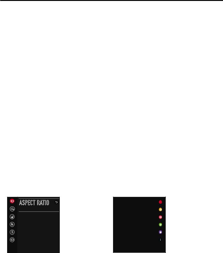
To determine the operating mode of the STB, press MENU on the Installer Remote. The menu displayed depends on the operating mode. See examples below. If the Function Menu appears, the STB is in a mode (FTG, PPV, etc.) that does not allow the end user to change the fundamental STB setup. If the STB setup menus appear, the STB is in Pass-through Mode.
Aspect Ratio ASPECT RATIO |
|
X |
|
|
|
||
Sound Out |
Function Menu |
STB Setup Menus |
|
Indicates the STB is not in |
Shows that the STB is in |
||
Aspect Ratio ^ |
|||
16:9 |
Pass-through Mode. While |
Pass-through Mode. |
|
Audio Mode |
the STB is in this mode, |
|
|
|
|
||
General |
Installer Menu settings can |
|
|
be accessed as read-only. |
|
||
|
|
||
Safety |
|
|
|
Accessibility |
|
|
206-4310 |
13 |
Pro:Centric Operation
Pro:Centric Interactive Menu Features
LG’s Pro:Centric application enables guests to locate and select television entertainment using an interactive channel guide, check the daily weather, and view hotel and surrounding amenities via custom billboards and points-of-interest maps.
Pro:Centric application features include:
•Portal and information screens/pages (including a “Welcome” page) that include branding logos.
•An optional customized user interface (custom “skins”).
•Billboards and points-of-interest maps that can be customized to focus on hotel amenities, local attractions and businesses, restaurants, news, events, etc.
•An optional Weather billboard that includes a local radar map, current conditions, and a four day forecast.
•An interactive channel guide that provides a channel list with channel icons. An electronic program guide (EPG) is an optional feature that displays up to three days of programming information viewable by channel and time.
•Video spooling that enables the hotel to deliver a video file to guest TVs for promotion and information purposes.
The Pro:Centric server Admin Client web editor/content wizard is provided for customer configuration of portal messages and billboards/maps.
Note: Customized content is typically defined by the service integrator and/or hotel administrators. LG does not provide hotel-specific content.
Pro:Centric Interactive Menu Navigation
An LG Pro:Centric-capable remote control provides access to both interactive menus and regular STB/ display features. Press PORTAL on the remote to access the interactive menus.
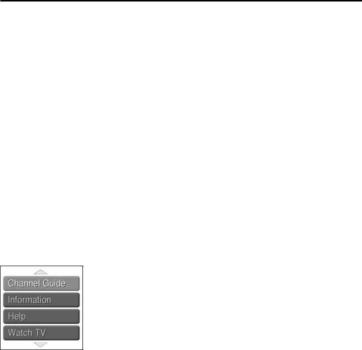
Note: Interactive menu options may vary, depending on Pro:Centric features enabled for the site. The following are default interactive menus.
Channel Guide
Shows available TV networks and logical channels. When available, EPG data provides additional channel and program information.
Information
Typically displays information on hotel amenities, for example, restaurants, in-room dining, business centers, facilities, etc., as well as information on local weather and attractions.
Help
Provides help for navigating the interactive menus.
Watch TV
Removes the interactive menu from the screen and returns to the previously tuned TV channel.
14 |
206-4310 |

Pro:Centric Operation (Cont.)
Pro:Centric Setup
Administration and management options for the Pro:Centric server are described in detail in the Pro:Centric Server Admin Client User Guide. This document describes only those settings that must be specified on the STB to enable Pro:Centric remote management and/or the Pro:Centric application.
•Remote management (E-Z Installation): The Pro:Centric server Admin Client provides remote management facilities for downloading software/firmware updates as well as facilities for downloading a Clone/Configuration (.tlx) file for FTG Mode configuration.
•Pro:Centric application: The application, which operates in conjunction with FTG and PPV Modes, comprises the Pro:Centric interactive menus/features described on the previous page. Pro:Centric application settings are managed via the Pro:Centric server Admin Client.
The Pro:Centric server settings can be configured using one of the methods described below.
STB in Factory Default State
When the STB is in a factory default state, the EZ-Manager Wizard provides automated or manual options for configuring the Pro:Centric server settings.
The EZ-Manager Wizard also provides a USB Configuration option that enables you to configure an STB for FTG Mode using a Clone/Configuration (.tlx) file stored on a USB memory device. The “.tlx” file incorporates
FTG Installer Menu settings, including Installer Menu items 098 PRO:CENTRIC and 119 DATA CHANNEL, which are used to set up the STB’s Pro:Centric feature.
Refer to “EZ-Manager Wizard” on pages 17 to 26 for further information on the EZ-Manager Wizard options.
Note: If Pro:Centric data delivery will be over IP and there is a Domain Name System (DNS) server at the site, you can create a “procentric.local” DNS entry for the Pro:Centric server that will enable automated
Pro:Centric IP configuration via the EZ-Manager. If there is no DNS entry for procentric.local, you will need to manually enter the Pro:Centric server IP address and port number during configuration.
STB in Pass-through Mode
If the STB is in Pass-through Mode, either:
•Set Installer Menu items 098 PRO:CENTRIC and 119 DATA CHANNEL to the appropriate values. See Installer Menu information on pages 31 to 41 for further details. Also, as necessary, refer to “Custom Master STB Setup” on pages 42 to 44 and/or cloning information on pages 45 to 51.
•Configure the appropriate Pro:Centric server settings in the IP Environment / Pro:Centric Menu. You must use this option, in particular, if you wish to configure IP settings for the Pro:Centric server. See
“Accessing the IP Environment Menu” on page 58 and “Pro:Centric Setup” on pages 62 to 64 for further information.
Note: When the STB is in either Pass-through Mode or FTG Mode, you can also leave Installer Menu item 119 DATA CHANNEL set to its default value (255) to enable the STB’s Data Channel Auto Search feature to set the DATA CHANNEL value. See item 119 description on page 40 for additional information.
STB in FTG Mode
If the STB is in FTG Mode, use the FTG File Manager software to update Installer Menu items #98 Pro:Centric and #119 Data Channel (along with their affiliated fields). Then, transfer the FTG Installer Menu settings to the STB. Refer to the FTG Mode overview on pages 12 to 13 for further information on FTG Mode operation and configuration. Also, see note above regarding the option to use the STB’s Data Channel Auto Search feature to set the DATA CHANNEL value.
206-4310 |
15 |

Setting the Video Output Resolution
The first time you turn ON the STB/display panel, a Please Select Video Output Resolution menu will be displayed, and you will need to select the appropriate option—720p, 1080p, 1366 x 768, or 2160p—for the STB’s video output format. You cannot proceed with STB configuration until you make a selection.
Refer to documentation for the applicable display panel(s) to determine the appropriate setting. The selected resolution should be compatible with the display panel’s native video resolution. For example, 2160p requires a UHD display panel.
PLEASE SELECT VIDEO OUTPUT RESOLUTION
720p
1080p
Note: After it is turned ON, the STB begins an initialization process, and it may take several minutes for the Please Select Video Output Resolution menu to be displayed.
1366 x 768
2160p
1.Use the Up/Down arrows on the Installer Remote to select the appropriate video output resolution option, and then press OK.
The STB’s default video output resolution is 720p. If you select this option, the Please Select Video Output Resolution menu will close and the EZ-Manager Wizard Welcome screen will be displayed (see pages 17 to 26 for information on the EZ-Manager Wizard). Proceed with Commercial Mode setup as required.
If you select one of the other three resolution options (1366 x 768 is selected/highlighted as the recommended resolution), a Changing Video Output Resolution message will be displayed, and the STB will reboot within a few seconds to change the resolution per your selection. Continue with step 2.
2.When the STB reboot is complete (it may take a few minutes), you will be prompted to confirm the new video output resolution. Use the arrow keys on the Installer Remote to select YES in the confirmation screen, and then press OK on the Installer Remote.
Note: If there is no user interaction within 10 seconds, or if you select “NO” in the confirmation screen, the STB will reboot and revert to the default resolution. After this reboot is complete, the Please Select Video Output Resolution menu will be redisplayed.
Once you select and confirm the video output resolution, the EZ-Manager Wizard will be displayed. Proceed with Commercial Mode setup as required.
Note: If required at a later time, you can also change the video output resolution in the STB Installer Menu (item 105 VID OUT FORMAT) or via USB memory device / “.tlx” file. In either case, the STB will need to reboot (see item 105 description on page 39 for additional information).
16 |
206-4310 |

EZ-Manager Wizard
The primary purpose of the EZ-Manager Wizard is to guide you through the process (automated or manual) of configuring the essential Installer Menu items for Pro:Centric operation. The wizard is initiated once the video output resolution is set (see previous page) and subsequently each time the STB/display panel is turned ON, until one of its configuration methods has been completed or the wizard is exited. Use the Installer Remote to make selections and complete each wizard step.
While the EZ-Manager Wizard is intended primarily for Pro:Centric-related configuration, the wizard also offers Zoning as well as USB configuration options.
•STB-5500s support the STB Zoning and Wi-Fi Zoning features, both of which enable locationspecific settings (see Reference section, “Using the STB’s Zoning Features,” for further information).
The EZ-Manager Wizard enables you to set the STB Zone # and/or the Wi-Fi Zone # in the STB as part of the configuration process.
•The EZ-Manager Wizard also enables you to access the STB Manager / USB download options as part of the configuration process, if desired, to perform USB configuration and/or update functions.
Caution: Do NOT unplug the STB power cord or remove the antenna cable or, if applicable, the LAN cable during the configuration process, as doing so will interrupt the current step and may corrupt the configuration data.
Before You Begin
•If you plan to create a Master STB Setup using the procedure described on pages 42 to 44, be sure to exit the EZ-Manager Wizard in order to avoid setting modes that may restrict the custom setup procedure. See also “Initiate Configuration or Exit the EZ-Manager Wizard” on the following page.
•If it has been completed or exited and therefore does not display, the EZ-Manager Wizard can be reactivated; however, this requires that you restore the STB to a factory default condition. See Reference section, “Restoring Factory Defaults on the STB(s),” for further information.
•Each wizard step is allotted a time frame after which the wizard proceeds without user interaction. If the Pro:Centric server is configured on the system and if no location-specific settings are required in the STB, for example, STB Zone, Wi-Fi Zone, Label, and/or Room Number settings, you can simply turn ON the STB/display, and once initiated, the wizard will proceed through each of the configuration steps with no further user interaction.
•If any of the configuration steps fails, you will see a “Diagnostics” screen with an indication of the failure. You will then have the opportunity to reinitiate the configuration process from the previous screen or exit the EZ-Manager Wizard.
•If you would like to enable the DIAL and/or SoftAP Media Share features or select pre-loaded/
Smart Launcher applications on an STB that will eventually be configured for FTG Mode, you will need to use the IP Environment Menu to do so before the STB is configured for FTG Mode. Refer to “IP Environment Setup” on pages 58 to 65 for information on the IP Environment Menu. See also “Custom Master STB Setup” on pages 42 to 44.
206-4310 |
17 |

EZ-Manager Wizard (Cont.)
Initiate Configuration or Exit the EZ-Manager Wizard
The Welcome screen provides a brief introduction to the EZ-Manager Wizard.
X
WELCOME TO THE EZ-MANAGER WIZARD
. Use the EZ-Manager Wizard to configure the STB for Pro:Centric operation or to configure the STB using a USB memory device.
. If a Pro:Centric server will not be installed, you may select NO PRO:CENTRIC below to disable the Pro:Centric feature of this STB and exit the EZ-Manager Wizard.
. If you simply wish to exit the EZ-Manager Wizard, select X in the top right corner of the screen.
Select NEXT to continue.
This wizard will start automatically in 10 seconds.
NO PRO:CENTRIC NEXT
Note: If there is no user action in this screen within 10 seconds, the wizard will proceed to the first configuration step. Once the wizard has proceeded, it is not possible to return to the Welcome
screen; however, if you simply wish to exit the wizard, you can do so by selecting the X button from
the subsequent screen(s).
From the Welcome screen, you have the following options:
•To proceed with the EZ-Manager Wizard, use the arrow keys on the Installer Remote to select/ highlight NEXT, and then press OK. Then, continue to the “STB Configuration Options” section on the following page.
•To exit the wizard, but retain the use of the Pro:Centric remote management feature on this STB (i.e., Installer Menu item 119 DATA CHANNEL set to 255) in the future, use the arrow keys
on the Installer Remote to select/highlight the |
X |
button at the top right of the screen, and then |
|
|
|
press OK. In the confirmation pop-up window, select EXIT, and then press OK once more on the Installer Remote.
•If you do not intend to install a Pro:Centric server on this system and you do not wish to use the wizard’s Zoning or USB configuration options, exit the wizard as follows: Use the arrow keys on the Installer Remote to select/highlight NO PRO:CENTRIC, and then press OK. This will disable the Pro:Centric feature of this STB (i.e., Installer Menu item 119 DATA CHANNEL will be set to
0) and exit the wizard. In the confirmation pop-up window, select EXIT, and then press OK once more on the Installer Remote.
18 |
206-4310 |

EZ-Manager Wizard (Cont.)
STB Configuration Options
From the STB Configuration Options screen, you can choose how to proceed with the configuration of this STB/display (assuming you do not opt to exit the wizard, which you may also do at any time).
Note: If you intend to use the Zoning feature(s) on the STB for location-specific configuration purposes, select the “Zones & Room Number” option from this screen and assign the appropriate STB Zone # and/or the Wi-Fi Zone # in the STB BEFORE you continue with additional configuration.
|
X |
STB CONFIGURATION OPTIONS |
|
01 |
. To configure the STB for Pro:Centric operation, select NEXT.
. To set the optional Zoning features, select ZONES & ROOM NUMBER.
ZONES & ROOM NUMBER
. To configure the STB using a USB memory device, select USB CONFIGURATION.
USB CONFIGURATION
This wizard will continue automatically in 60 seconds.
NEXT
Note: If there is no user action in this screen within one minute, the wizard will automatically continue to the next configuration step.
Use the Up/Down arrow keys on the Installer Remote to navigate between options on this screen.
•To continue with Pro:Centric configuration, select NEXT (default) and press OK on the Installer Remote. See “Configure Pro:Centric Settings” on pages 21 to 25 for additional information.
•To set the Zoning feature(s) on the STB, select ZONES & ROOM NUMBER. See “Zones and Room Number Assignments” below for further information.
•To access the STB Manager / USB download options, select USB CONFIGURATION. See “USB Configuration” on pages 25 to 26 for further information.
Note: If you choose to exit the EZ-Manager Wizard from this point on, you will have the option to save any settings made by selecting SAVE & EXIT in the exit confirmation pop-up window. Or, you can exit the wizard without saving any settings by simply selecting EXIT in the confirmation pop-up window.
Zones and Room Number Assignments
You may complete one or more of the fields in the Zones, Label, and Room Number screen or leave them at their default settings (STB Zone and Wi-Fi Zone) or blank (Label and Room Number), as desired. However, if you intend to use either of the Zoning features—STB Zoning and/or Wi-Fi Zoning—on this STB, you MUST specify the appropriate values in the STB Zone and/or Wi-Fi
Zone fields as described on the following page. See also Reference section, “Using the STB’s Zoning Features,” for further information.
206-4310 |
19 |

EZ-Manager Wizard (Cont.)
Note: Zoning features are only applicable for STBs that will be configured using a “.tlx” file (local or remote configuration).
ZONES, LABEL, AND ROOM NUMBER
Wi-Fi Zone |
|
|
. |
|
< |
0 |
> |
. |
|
STB Zone |
|
|
||
|
|
|
||
< |
0 |
> |
|
|
Label |
|
|
. |
|
< |
----- |
> |
||
|
.
Room Number
Room Number
If creating Wi-Fi Zones for AP settings, select the appropriate Wi-Fi |
|
Zone # (1-99) based on the Wi-Fi Zone in which this STB is installed. |
|
If creating Zones for Installer Menu settings and/or Channel Mapping, |
|
select the appropriate STB Zone # (0-8) based on the Zone in which |
|
this STB is installed. (See Commercial Mode Setup Guide for more |
|
information.) |
02 |
|
|
Select a Label and/or input the Room Number, as required. |
|
When done, select SAVE to continue. |
|
BACK SAVE
1.Complete the appropriate field(s) as described below. Use the Left/Right arrow keys on the Installer Remote to navigate between each of the fields.
•Wi-Fi Zone: Enables you to set a Wi-Fi Zone # so that the STB can be configured with a particular access point’s login data for wireless networking. Login data (i.e., SSID, security type, and security key) may be provided in a Clone/Configuration (.tlx) file.
To assign a Wi-Fi Zone, navigate to the Wi-Fi Zone field at the top left of the screen, and use the Left/Right arrow keys to specify the desired Wi-Fi Zone # (1–99).
•STB Zone: Enables you to set an STB Zone # so that the STB can be configured with
Installer Menu and/or Setup Menu settings intended only for the assigned Zone. The Installer Menu and/or Setup Menu settings may be provided in a Clone/Configuration (.tlx) file. If the STB is being configured for FTG Mode, theSTB Zone # setting also allows the STB to omit channels that have been restricted in the FTG Channel Map.
To change the STB Zone from its default value (0), navigate to the STB Zone field, and use the Left/Right arrow keys to specify the desired STB Zone # (1–8).
•Label: Allows you to select a North, South, East, or West text label for this STB. In the Label field, use the Left/Right arrow keys to select the applicable label.
•Room Number: Allows you to specify the number of the room—up to 16 characters—in which the STB is located. To enter a room number, navigate to the Room Number field and press
OK. You can then use the number keys on the Installer Remote to direct enter a room number, or you can use the arrow keys to select the appropriate alphanumeric character(s) from the pop-up virtual keyboard at the bottom of the screen. When you are done, select Enter from the virtual keyboard, and then press OK on the Installer Remote.
Note: The STB name (default: STB’s serial number) will be changed to the room number specified here. See “Media Share Setup” on pages 64 to 65 for further information on the STB name.
2.When you are ready to continue, use the arrow keys to select SAVE, and then press OK on the
Installer Remote to return to the STB Configuration Options screen. Then, proceed as required; i.e., select NEXT to configure Pro:Centric settings or select USB CONFIGURATION to use a USB memory device to complete the configuration.
20 |
206-4310 |
EZ-Manager Wizard (Cont.)
Configure Pro:Centric Settings
Once you select “NEXT” from the STB Configuration Options screen, the Searching for Pro:Centric
Server screen is displayed.
Note: Select the “BACK” button, where available, to check previous settings, as necessary.
X
SEARCHING FOR PRO:CENTRIC SERVER...
This step automatically searches for the Pro:Centric server.
If there is no Pro:Centric server installed, you do not need to continue with this procedure.
In this case, you can either select X in the top right corner of the screen to exit or select MANUAL
PRO:CENTRIC below to enter the Pro:Centric server settings manually.
Status: Tuning channel 30
STB is now searching the pre-defined channels for the data channel...
BACK |
MANUAL PRO:CENTRIC |
03 |
|
You have the following options:
•You can allow the EZ-Manager Wizard to proceed with a series of automated steps to configure the STB for Pro:Centric operation and then to look for the Pro:Centric application and maintenance
(E-Z Installation) files to download. In this case, the wizard uses a search algorithm to determine the Data Channel and the Pro:Centric Application Mode to set in the STB.
Continue with the “Automated Pro:Centric Configuration” subsection below.
•If you already know the settings (i.e., Data Channel and Pro:Centric Application Mode) that need to be configured in order for the STB to connect to the Pro:Centric server and/or if the Pro:Centric server is not yet installed, you may expedite the setup process by entering this data manually.
Continue with the “Manual Pro:Centric Configuration” subsection on page 23.
Automated Pro:Centric Configuration
Note: If the server is not yet configured on the system, use the manual configuration option to configure the Pro:Centric operation. See also note below.
Note: If Pro:Centric data delivery will be over IP and there is a DNS server at the site, you can create a DNS entry “procentric.local” for the Pro:Centric server that will enable automated
Pro:Centric IP configuration via the EZ-Manager. If there is no DNS entry for procentric.local, you must use the manual configuration option to configure the Pro:Centric IP operation.
Once the Pro:Centric data channel is found (a Pro:Centric Server Was Found screen will be displayed) and the Pro:Centric Application Mode is determined, the wizard will advance to the
Processing the Pro:Centric Configuration screen, which shows the progress of the data downloads (see example on following page). Note that some steps may require a few minutes.
(Continued on next page)
206-4310 |
21 |

EZ-Manager Wizard (Cont.)
(Continued from previous page)
If the process is successful, no further user interaction is required, though, in some instances, where the option (for example “NEXT”) is available, you may manually move forward to subsequent steps within the wizard to speed up the process.
PROCESSING THE PRO:CENTRIC CONFIGUR...
Downloading the Pro:Centric application files takes a few minutes. Please wait...
2%
Retrieving files from data channel 70
Application files |
In progress... |
Maintenance Files |
Synchronizing... |
Warning - Do not remove AC power or the signal cables during these steps.
Note: If, after completing the search, the STB is unable to find the Pro:Centric data channel (while the Searching for Pro:Centric Server screen is on display), the wizard will stop and show a Diagnostics screen that enables you to manually return to the previous screen (to reinitiate the configuration) or exit the wizard.
When the Pro:Centric Configuration is complete, an EZ-Manager Configuration Complete screen is displayed (see example below), and after 10 seconds, the wizard exits, and the STB turns OFF.
EZ-MANAGER CONFIGURATION COMPLETE
STB will turn off in 10 second(s)
Installed Components |
|
Installed Components |
|
|
|
Pro:Centric Application |
GEM application downloaded |
|
Maintenance Files |
Pro:Centric Application |
GEM application downloaded |
STB-5500_Config.tlx |
LY970H_Config.tlx |
|
|
Maintenance Files |
|
REBOOT |
TURN OFF |
Note: With the EZ-Manager Configuration Complete screen on display, you can also manually turn off or reboot the STB. If desired, select TURN OFF or REBOOT, respectively, and then press OK on the Installer Remote.
22 |
206-4310 |

EZ-Manager Wizard (Cont.)
Manual Pro:Centric Configuration
1.With the Searching for Pro:Centric Server screen on display, use the Left/Right arrow keys on the Installer Remote to select MANUAL PRO:CENTRIC at the bottom right of the screen, and then press OK.
In the Pro:Centric Manual Configuration screen (see examples below), you will be able to configure the appropriate Pro:Centric settings in the STB. Use the Up/Down arrow keys on the Installer Remote to navigate between fields.
|
|
|
|
|
X |
|
PRO:CENTRIC MANUAL CONFIGURATION |
|
|
||||
|
Pro:Centric Manual Configuration Screen |
|||||
Pro:Centric Mode |
< |
CONFIGURATION ONLY |
> |
|
|
|
Media Type |
< |
RF |
> |
|
|
with RF Media Fields |
Data Channel |
< |
1 |
> |
|
|
Note: By default, the Pro:Centric Manual |
Signal Strength |
|
|
|
0% |
|
|
|
|
|
|
Configuration screen initially shows RF |
||
Signal Quality |
|
|
|
0% |
|
|
data channel not found |
|
|
configuration fields. |
|||
|
|
|
|
|||
|
|
|
|
|
||
BACK SEARCH |
|
|
|
|
03 |
|
|
|
|
|
|
|
|
|
|
|
|
|
|
|
X
PRO:CENTRIC MANUAL CONFIGURATION
Pro:Centric Mode |
< |
CONFIGURATION ONLY |
> |
Pro:Centric Manual Configuration Screen |
||
Media Type |
|
< |
|
IP |
> |
with IP Media Fields |
Server Address |
|
< |
|
IP Address |
> |
|
IP Address |
|
0 |
0 |
0 |
0 |
|
IP Port |
|
|
|
0 |
|
|
|
|
|
|
|
|
|
|
|
IP server not found |
|
|
|
|
BACK |
SEARCH |
|
|
|
|
03 |
|
|
|
|
|
||
2.In the Pro:Centric Mode field, use the Left/Right arrow keys to select the appropriate Pro:Centric
Application Mode—FLASH, GEM, HTML, or CONFIGURATION ONLY.
Note: For remote management only, select CONFIGURATION ONLY. The STB will search for E-Z Installation data downloads; however, Pro:Centric application data will not be downloaded, i.e., Installer Menu item 098 PRO:CENTRIC will be set to 0.
3.Refer to the appropriate subsection below, depending on the Pro:Centric server configuration, to complete the remaining fields.
(Continued on next page)
206-4310 |
23 |

EZ-Manager Wizard (Cont.)
(Continued from previous page)
RF Configuration
a)In the Media Type field, use the Left/Right arrow keys to select RF.
b)In the Data Channel field, use the Left/Right arrow keys to select the RF channel number that will be used by the Pro:Centric server as its data channel. The Data Channel value can be set from 1 to 135. *
IP Configuration
a)In the Media Type field, use the Left/Right arrow keys to select IP.
Note: When you select “IP” as the Media Type, the default RF Data Channel and Signal
Strength/Quality fields are replaced with ServerAddress, IPAddress, and IP Port fields.
b)The Server Address field provides the option to specify the domain name of the Pro:Centric server instead of the server’s IP address. Use the Left/Right arrow keys to select the desired option—IPAddress or Domain Name—for defining the server.
c)Depending on your selection in the previous step, either:
•Enter the Pro:Centric server IP address in the IP Address field. The IP address must match the IPv4 multicast address that is set in the Pro:Centric server.
•Enter the Pro:Centric server domain name in the Domain Name field. Note that in order for the domain name to be resolved to an IP address, there must be a DNS entry for the domain name.
For each data entry field: Use the arrow keys to select the field and press OK. Then, you can either use the number keys on the Installer Remote to direct enter data values, or you can use the arrow keys to select the appropriate number(s)/alphanumeric character(s) from the pop-up virtual keyboard displayed at the bottom of the screen. When you are done, select Enter from the virtual keyboard, and then press OK on the Installer Remote.
d)Enter the Pro:Centric server port number in the IP Port field. The port number must match the port number that is set in the Pro:Centric server.
4.Once all fields are completed as required, you have two options:
• To save the data entered and exit the wizard, use the arrow keys to select the |
X |
button at the |
|
|
|
top right of the screen, and then press OK. In the subsequent pop-up confirmation window, select SAVE & EXIT, and then press OK once more. The Pro:Centric application and/or E-Z Installation data will be downloaded to the STB at a later time. This option is useful, in particular, if the Pro:Centric server has not yet been configured.
•To initiate a real-time download of Pro:Centric application and/or E-Z Installation data, use the arrow keys to select SEARCH and press OK to verify the configuration data provided in step 3. When the data is verified, the “SEARCH” button becomes a “NEXT” button. Select NEXT and press OK to continue (see also note below).
Note: With RF configuration, Pro:Centric server data must be present on the RF channel selected as the STB’s Data Channel in order for you to select “NEXT” (you will see a “data channel found” message below the Signal Quality indicator). With IP configuration, Pro:Centric server data must be present via the wired LAN cable connection in order for you to select
“NEXT” (you will see a “IP server found” message below the IP Port field).
(Continued on next page)
* PCS150R and later Pro:Centric servers do not support HRC or IRC cable channel frequencies.
24 |
206-4310 |

EZ-Manager Wizard (Cont.)
(Continued from previous page)
If you opt to initiate a real-time download in the last step, the EZ-Manager Wizard will proceed with the Pro:Centric application and/or E-Z Installation data downloads (see Processing the Pro:Centric
Configuration screen example on page 22). When the Pro:Centric configuration is complete, an EZ-Manager Configuration Complete screen (see example on page 22) is displayed, and after 10 seconds, the wizard exits, and the STB turns OFF.
Note: With the EZ-Manager Configuration Complete screen on display, you can also manually turn off or reboot the STB. If desired, select TURN OFF or REBOOT, respectively, and then press OK on the Installer Remote.
USB Configuration
STB Manager / USB download options enable you to download configuration or software files individually from a USB memory device to the STB. You can also use the Ez Download utility available from the menu to select multiple types of files to be downloaded at one time using one process.
Each of the USB download functions requires that you have the appropriate file(s) loaded on a
USB memory device. If you wish to perform a software update or download background image files, the software update/image file(s) must be stored in a folder named “LG_DTV” in the root directory of the USB memory device. Clone/Configuration (.tlx) files should simply be stored in the root directory of the USB device.
The procedure below assumes the desired file(s) is/are already loaded onto the USB device. For further information on the STB Manager / USB download options and file requirements, and/or for information on creating Clone/Configuration (.tlx) files, refer to the appropriate section(s) in this document.
Before You Begin
•If you intend to use the Zoning feature(s) on this STB, make sure to assign the appropriate STB Zone # and/or Wi-Fi Zone # in the EZ-Manager’s Zones, Label, and Room Number screen
BEFORE continuing with USB Configuration. See “STB Configuration Options” on page 18 for further information.
•Ensure the USB device to be used has been formatted with FAT format.
•When creating files to be downloaded, avoid using special characters (?, &, @, etc.) in filenames.
•Refer to “Ez Download Utility” on pages 27 to 30 for further information on the Ez Download utility.
•Refer to “Custom Master STB Setup” on pages 42 to 44 for information on creating a Clone (.tlx) file, and/or refer to “Creating an FTG Configuration File” on pages 52 to 53 for information on creating a FTG Configuration (.tlx) file for FTG Mode configuration.
•See Reference section, “Downloading Background Images using a USB Memory Device,” for background image guidelines.
•See Reference section, “Updating STB Software using a USB Memory Device,” for further information on software updates.
USB Configuration via EZ-Manager Wizard
With either the STB Configuration Options or the Zones, Label, and Room Number screen on display, proceed as follows to configure the STB/display using the USB memory device.
206-4310 |
25 |

EZ-Manager Wizard (Cont.)
1.Insert the USB memory device with the appropriate file(s) into either of the STB’s USB ports.
2.Use the arrow keys on the Installer Remote to select USB CONFIGURATION, and then press
OK.
You will be redirected to the STB Manager / USB download options.
STB MANAGER
Ez Download
USB 1: Device Name
 Ez Download
Insert Background Image(s)
Update STB Software
Update PTC Software
Import Clone File
Diagnostics
Select the file(s) to download, and then select UPDATE below.
 Insert Background Image(s)
None
Update STB Software
STB_CPU_SW.epk
Image1.jpg Image2.jpg
Update PTC Software
STB_PTC_SW.txt
Import Clone File
STB_IM.tlx
Image4.jpg Image5.jpg
UPDATE
Image7.jpg Image8.jpg
X
USB DEVICE
>
Image3.jpg
Image6.jpg
Image9.jpg |
< |
|
Note: You can select the button at the top right corner of the screen and press OK on the
X
Installer Remote at any time to return to the EZ-Manager Wizard.
Note: Ez Download is always selected by default when you initially access the STB Manager. Also note that Diagnostics is for service use only.
3.If more than one USB memory device is currently connected to the STB, be sure to select the
USB device that contains the file(s) you wish to use. If necessary, use the arrow keys on the
Installer Remote to select/highlight the USB DEVICE button at the top right of the screen and press OK. Then, use the Up/Down arrow keys to select the appropriate USB device from the pop-up list of USB devices displayed at the top of the screen.
4.Select the appropriate option from the STB Manager, and initiate the desired download(s).
Update progress will be shown on the screen. Do NOT remove the USB device while updates are in progress. When the update process is complete, the STB will reboot. Upon restart, depending on the type of update(s) completed, either the EZ-Manager STB Configuration Options screen will be redisplayed (software and/or image updates only) or the STB will tune according to the Start Channel setting in the Installer Menu (STB configured with Clone/Configuration file).
Note: If the STB Configuration Options screen is redisplayed (software and/or image updates only), you can either proceed with configuration via the EZ-Manager Wizard or exit the EZ-Manager Wizard, as required.
Note: If you updated the STB configuration with a Clone/Configuration file that included a change to Installer Menu item 105 VID OUT FORMAT, when the reboot is complete, you will be prompted to confirm the new video output resolution. See item 105 description on page 39 for further information.
5.Remove the USB memory device, and verify that the appropriate configuration/update(s) is/are resident on the STB.
26 |
206-4310 |

Ez Download Utility
The Ez Download utility, available from the STB Manager, enables you to select multiple files at one time from the files loaded on a USB memory device. You may use this utility to download any one or all of the following to an STB:
•One Clone or FTG Configuration (.tlx) file
•One STB (CPU) software update
•One PTC software update
•Up to 12 background images
Before You Begin
•Ensure the USB device has been formatted with FAT format.
•Software update and background image files must be stored in a folder named “LG_DTV” in the root directory of the USB memory device. Clone/Configuration (.tlx) files should simply be stored in the root directory of the USB device.
•If the EZ-Manager Wizard appears on the screen when you turn ON the STB/display, you can use the wizard’s “USB Configuration” option to access the Ez Download utility (see “STB Configuration Options” and/or “USB Configuration” on pages 19 and 25, respectively, as necessary).
•If the STB is currently in Pass-through Mode and you intend to use the Zoning feature(s) on this
STB for location-specific configuration purposes, make sure to assign the appropriateSTB Zone # and/or Wi-Fi Zone # in the STB when directed to do so in the procedure below.
•When creating files to be downloaded, avoid using special characters (?, &, @, etc.) in filenames.
•Refer to “Custom Master STB Setup” on pages 42 to 44 for information on creating a Clone (.tlx) file, and/or refer to “Creating an FTG Configuration File” on pages 52 to 53 for information on creating an FTG Configuration (.tlx) file for FTG Mode configuration.
•See Reference section, “Downloading Background Images using a USB Memory Device,” for background image guidelines.
•See Reference section, “Updating STB Software using a USB Memory Device,” for further information on software updates.
Caution: Do not unplug the STB power cord or remove the USB memory device during a data download, as doing so may cause the STB to malfunction or harm the USB device, respectively.
Accessing and Using the Ez Download Utility
1.If it is not ON already, turn ON the STB/display panel.
2.The next step depends on whether the EZ-Manager Wizard appears on the screen when you turn ON the STB/display:
•If the wizard is displayed, you can access the Ez Download utility via the wizard, as indicated above (see “Before You Begin”). However, to continue with this procedure and access the Ez Download utility from the STB menus, exit the EZ-Manager Wizard. Then, continue with step 3.
•If the wizard is not displayed, go directly to step 3.
(Continued on next page)
206-4310 |
27 |
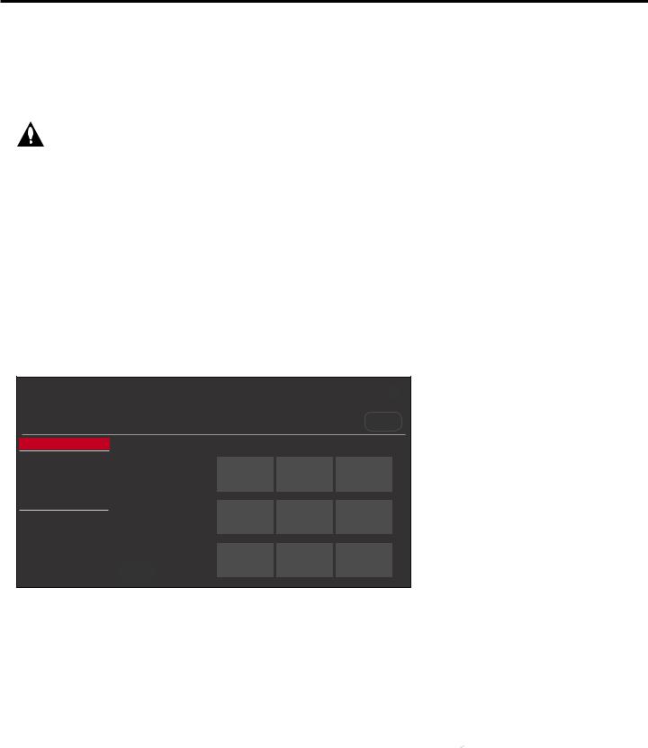
Ez Download Utility (Cont.)
(Continued from previous page)
3.If the STB is currently in Pass-through Mode, you would like to transfer (import) a “.tlx” file to the STB via the Ez Download utility, and you intend to use one or both of the STB’s Zoning feature(s), assign the appropriate STB Zone # and/or Wi-Fi Zone # in the STB at this time. See Reference section, “Using the STB’s Zoning Features,” for further information.
Note: In order for the proper location-specific STB Zone and/or Wi-Fi Zone profile data to be applied, the Zone designation(s) must be assigned in the Target STB(s) BEFORE you continue with the Ez Download utility.
4.Insert the USB memory device with the appropriate file(s) into either of the STB’s USB ports.
5.To access the STB Manager from the STB menus:
•Press MENU on the Installer Remote to display the STB setup menus (STB is in Pass-through Mode) or the Function Menu (STB is not in Pass-through Mode).
•If the Quick Settings Menu is displayed at the right of the screen (i.e., the STB is in Pass-
through Mode), select the All Settings  menu icon and press OK to access the advanced STB setup menus.
•Use the arrow navigation keys to select/highlight either the General menu icon from the STB setup menus or the Safety menu icon from the Function Menu. Then, press the number “7” key a total of seven times.
Note: Ez Download is always selected by default when you initially access the STB Manager. Also note that Diagnostics is for service use only.
STB MANAGER
Ez Download
USB 1: Device Name
 Ez Download
Insert Background Image(s)
Update STB Software
Update PTC Software
Import Clone File
Diagnostics
Select the file(s) to download, and then select UPDATE below.
 Insert Background Image(s)
None
Update STB Software
STB_CPU_SW.epk
Image1.jpg Image2.jpg
Update PTC Software
STB_PTC_SW.txt
Import Clone File
STB_IM.tlx
Image4.jpg Image5.jpg
UPDATE
Image7.jpg Image8.jpg
X
USB DEVICE
>
Image3.jpg
Image6.jpg
Image9.jpg |
< |
|
6.If more than one USB memory device is currently connected to the STB, be sure to select the
USB device that contains the file(s) you wish to use. If necessary, use the arrow keys on the
Installer Remote to select/highlight the USB DEVICE button at the top right of the screen and press OK. Then, use the Up/Down arrow keys to select the appropriate USB device from the pop-up list of USB devices displayed at the top of the screen.
(Continued on next page)
28 |
206-4310 |

Ez Download Utility (Cont.)
(Continued from previous page)
USB Device
 USB 1: Device 1
USB 2: Device 2
7.If it is not currently selected, use the arrow keys to select Ez Download, and then press OK.
As illustrated in the example above, when Ez Download is selected, a list of files/file types is displayed on the screen. Remember that Background Image, STB Software (CPU) and PTC
Software files must be stored in the LG_DTV folder and the Clone/Configuration (.tlx) files must be stored in the root directory on the USB device.
Note: Press on the Installer Remote or select the |
X |
button in the top right corner of the |
|
|
|
screen to exit the STB Manager (if accessed from the STB menus, you may also press EXIT on the Installer Remote to exit). If you accessed the STB Manager via the EZ-Manager Wizard, you will be returned to the last screen on display before you selected the “USB Configuration” option. If you accessed the STB Manager via the STB menus, you will be returned to program viewing.
8.To select a file:
•Use the arrow keys on the Installer Remote to select/highlight the appropriate file type field, and then press OK. A list of available files will be displayed to the right of the file type fields.
•Then, use the arrow keys to select the desired file.
Note: With the exception of background image files, the utility will only allow you to select one of each file type for downloading. For example,if there are two files in the Ez Download “Import Clone File” list, you can only select one or the other of those two files.
Note: The initial default value for each file type is “None.” After the Ez Download utility is run, a file is automatically created and stored on the USB device that was used. The file, which will have a “.dzm” file extension, maintains a history of the file(s) previously used with the Ez Download utility. The next time(s) you use this USB device with the Ez Download utility, the file(s) selected for the last download will be pre-selected for the current download, thus facilitating the process of configuring additional STB-5500s using the same USB device.
Note: The current STB software (CPU) or PTC software version is always displayed above the listing of available STB software and PTC software files, respectively. Ensure the software version of the selected file is the correct version before applying the update to this STB.
9.If a Clone/Configuration (.tlx) file that includes an FTG Channel Map is selected, a Channel Tuning / Channel Banner Display field will be displayed at the right of the screen. If the FTG
Channel Map comprises RF channels and Aux inputs only (the latter designated by 130-0 through 137-0), you can choose the format for the channel tuning/banner display. Use the arrow keys on the Installer Remote to select Logical tuning or Physical tuning. A checkmark will appear at the left of the selected option. Logical tuning is selected by default.
Note: If an FTG Channel Map includes IP channels, only logical tuning is available. Also, if the selected “.tlx” file does not include an FTG Channel Map, the message, “No Channel Map in Clone file,” will be displayed at the right of the screen.
(Continued on next page)
206-4310 |
29 |

Ez Download Utility (Cont.)
(Continued from previous page)
10.When you are ready to continue, use the arrow keys on the Installer Remote to select UPDATE, and then press OK.
Update progress will be shown in a new screen. Do NOT remove the USB device while updates are in progress. When the Ez Download process is complete, an overview of the results will briefly be displayed and then, the STB will reboot.
11.Remove the USB memory device, and verify that the appropriate configuration/update(s) is/are resident on the STB.
Note: If you updated the STB configuration with a Clone/Configuration file, upon restart (and, if applicable, confirmation of new video output resolution—see note below), the STB tunes according to the Start Channel setting in the Installer Menu. If a Start Channel is specified, the STB will tune to that channel, though in the case of FTG Mode configuration, a channel banner will only be displayed if the Start Channel is included in the FTG Channel Map (depending on your selection in step 9, the channel banner will display either the Start Channel’s logical channel number or physical RF channel number). Otherwise, the STB will either return to the last channel tuned (STB in Pass-through Mode) or tune to the first channel in the FTG Channel Map (STB in FTG Mode). In the latter case, remember that the channels in the FTG Channel Map are always arranged in logical order, regardless of your selection in step 9.
Note: If you updated the STB configuration with a Clone/Configuration file that included a change to Installer Menu item 105 VID OUT FORMAT, when the reboot is complete, you will be prompted to confirm the new video output resolution. See item 105 description on page 39 for further information.
30 |
206-4310 |
 Loading...