


Internal Use Only
http://biz.lgservice.com
Air Conditioner
SVC MANUAL(General)
CAUTION
Before Servicing the unit, read the safety precautions in General SVC manual. Only for authorized service personnel.

Air Conditioner Service Manual
TABLE OF CONTENTS
Part 1 General Information .......................................................................................................... |
3 |
|
1. |
Safety Precautions........................................................................................................ |
4 |
2. |
Model Line Up................................................................................................................ |
7 |
3. |
Nomenclature ................................................................................................................ |
8 |
Part 2 Functions & Controls...................................................................................................... |
10 |
|
1. |
List of Functions & Accessory................................................................................... |
11 |
2. |
Air flow ........................................................................................................................ |
14 |
3. |
Air purifying................................................................................................................. |
16 |
4. |
Installation Functions................................................................................................. |
17 |
5. |
Reliability ..................................................................................................................... |
21 |
6. |
Convenience Functions & Controls ......................................................................... |
22 |
7. |
Special Function & KIT............................................................................................... |
32 |
Part 3 Basic Control .................................................................................................................. |
35 |
|
1. |
Normal operation ........................................................................................................ |
36 |
2 Compressor control .................................................................................................... |
36 |
|
3. |
EEV( Electronic Expansion Valve) control ............................................................... |
36 |
Part 4 Trouble Shooting ........................................................................................................... |
37 |
|
1. |
Self-diagnosis Function ............................................................................................ |
38 |
2. Pump Down ................................................................................................................ |
40 |
|
3. |
Evacuation (All amount of refrigerant leaked) ........................................................ |
41 |
4. |
Gas Charging (After Evacuation).............................................................................. |
42 |
5. |
Cycle Part.................................................................................................................... |
43 |
6. |
Electronic Parts.......................................................................................................... |
44 |
Copyright ©2012 LG Electronics. Inc. All right reserved. |
- 2 - |
Only for training and service purposes |
LGE Internal Use Only |
|

Part 1 General Information
Part 1 General Information
1. |
Safety Precautions ............................................................................................................ |
4 |
2. |
Model Line Up..................................................................................................................... |
7 |
3. |
Nomenclature...................................................................................................................... |
8 |
Copyright ©2012 LG Electronics. Inc. All right reserved. |
- 3 - |
Only for training and service purposes |
LGE Internal Use Only |
|

Part 1 General Information
1. Safety Precautions
To prevent injury to the user or other people and property damage, the following instructions must be followed.
νIncorrect operation due to ignoring instruction will cause harm or damage. The seriousness is classified by the following indications.
This symbol indicates the possibility of death or serious injury.
This symbol indicates the possibility of injury or damage to properties only.
ν Meanings of symbols used in this manual are as shown below.
Be sure not to do.
Be sure to follow the instruction.
Dangerous Voltage
1.1 Cautions in Repair
Be sure to disconnect the power cable plug from the plug socket before disassembling the equipment for a repair.Internal components and circuit boards are at main potential when the equipment is connected to the power cables. This voltage is extremely dangerous and may cause death or severe injury if come in contact with it.
Do not touch the discharging refrigerant gas during the repair work.
The discharging refrigerant gas.The refrigerant gas can cause frostbite.
Release the refrigerant gas completely at a well-ventilated place first.
Otherwise, when the pipe is disconnected, refrigerant gas or refrigerating machine oil discharges and it Can cause injury.
When the refrigerant gas leaks during work, execute ventilation. If the refrigerant gas touches to a fire, poisonous gas generates. A case of leakage of the refrigerant and the closed room full with gas is dangerous because a shortage of oxygen occurs. Be sure to execute ventilation.
When removing the front panel or cabinet, execute short-circuit and discharge between high voltage capacitor terminals. If discharge is not executed, an electric shock is caused by high voltage resulted in a death or injury.
Do not turn the air-conditioner ON or OFF by plugging or unplugging the power plug. There is risk of fire or electrical shock.
Copyright ©2012 LG Electronics. Inc. All right reserved. |
- 4 - |
Only for training and service purposes |
LGE Internal Use Only |
|
Part 1 General Information
Do not use a defective or underrated circuit breaker. Use the correctly rated breaker and fuse. Otherwise there is a risk of fire or electric shock.
Install the panel and the cover of control box securely. Otherwise there is risk of fire or electric shock due to dust, water etc.
Indoor/outdoor wiring connections must be secured tightly and the cable should be routed properly so that there is no force pulling the cable from the connection terminals. Improper or loose connections can cause heat generation or fire.
Do not touch, operate, or repaire the product with wet hands. Hoding the plug by hand when taking out. Otherwise there is risk of electric shock or fire.
Use a vacuum pump or Inert (nitrogen) gas when doing leakage test or air purge. Do not compress air or Oxygen and Do not use Flammable gases.
Otherwise, it may cause fire or explosion.
- There is the risk of death, injury, fire or explosion.
Do not turn on the breaker under condition that front panel and cabinet are removed.
Be sure to earth the air conditioner with an earthing conductor connected to the earthing terminal.
Conduct repair works after checking that the refrigerating cycle section has cooled down sufficiently. Otherwise, working on the unit, the hot refrigerating cycle section can cause burns.
Do not tilt the unit when removing panels. Otherwise, the water inside the unit can spill and wet floor.
Do not use the welder in a well-ventilated place. Using the welder in an enclosed room can cause oxygen deficiency.
Be sure to turn off power switch before connect or disconnect connector, or parts damage may be occurred.
Copyright ©2012 LG Electronics. Inc. All right reserved. |
- 5 - |
Only for training and service purposes |
LGE Internal Use Only |
|
Part 1 General Information
1.2 Inspections after Repair
Check to see if the power cable plug is not dirty or loose. If the plug is dust or loose it can cause an electrical shock or fire.
Do not use a joined power cable or extension cable, or share the same power outlet with other electrical appliances. otherwise, it can cause an electrical shock, excessive heat generation or fire.
Do not insert hands or other objects through the air inlet or outlet while the product is operating. There are sharp and moving parts that could cause personal injury.
Do not block the inlet or outlet of air flow. It may cause product failure
Check to see if the parts are mounted correctly and wires are connected.
Improper installation and connections can cause an electric shock or an injury.
Check the installation platform or frame has corroded. Corroded installation platform or frame can cause the unit to fall, resulting in injury.
Be sure to check the earth wire is correctly connected.
After the work has finished, be sure to do an insulation tset to check the resistance is 2[Mohm] or more between the charge section and the non-charge metal section (Earth position). If the resistance value is low, a disaster such as a leak or electric shock is caused at userʼs side.
Check the drainage of the indoor unit after the repair. If drainage is faulty the water to enter the room and wet floor.
Copyright ©2012 LG Electronics. Inc. All right reserved. |
- 6 - |
Only for training and service purposes |
LGE Internal Use Only |
|
Part 1 General Information
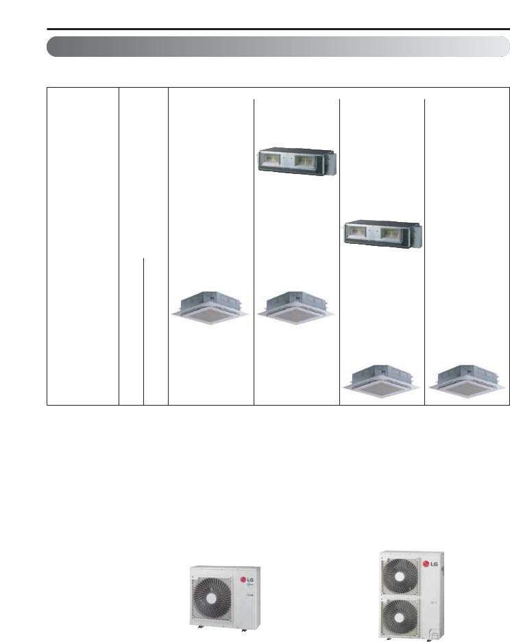
2.Model Line Up
2.1Indoor units
|
Category |
Chassis |
|
Capacity Index[kBtu/h] |
|
||
|
Name |
18 |
24 |
36 |
42 |
||
|
|
|
|||||
|
|
|
|
|
|
|
|
|
|
|
|
|
ABNH24GGLA2 |
|
|
|
|
|
|
|
[LHN240HV] |
|
|
|
|
|
BG |
|
|
|
|
|
Ceiling |
High |
|
|
|
|
|
|
Conceal |
Static |
|
|
|
|
|
|
|
|
|
ABNH36GRLA2 |
|
||
|
ed Duct |
Pressur |
|
|
|
|
|
|
|
|
|
|
|
[LHN360HV] |
|
|
|
|
BR |
|
|
|
|
|
|
|
|
|
|
|
|
|
|
ATNH18GPLE2 |
ATNH24GPLE2 |
|
|
|
[LCN187HV] |
[LCN247HV] |
|
|
|
TP |
|
|
Ceiling |
4way |
|
|
|
Cassette |
|
ATNH36GMLE2 |
ATNH42GMLE2 |
|
|
|
|||
|
|
|
||
|
|
|
[LCN367HV] |
[LCN427HV] |
|
|
TM |
|
|
2.2 Outdoor units
DC Inverter |
AUUW18GD2 |
AUUW24GD2 |
|
AUUW36GD2 |
AUUW42GD2 |
[LUU187HV] |
[LUU247HV] |
|
[LUU367HV] |
[LUU427HV] |
|
|
|
||||
|
|
|
|
|
|
No. of connectable |
|
|
1 |
|
|
indoor units |
|
|
|
||
|
|
|
|
|
|
|
|
|
|
|
|
Total Capacity index of |
|
|
|
|
|
conectable indoor |
18 |
24 |
|
36 |
42 |
units(kBtu) |
|
|
|
|
|
|
|
|
|
|
|
Power supply |
|
1Ø, 203-230V, 60Hz |
|
||
|
|
|
|
|
|
Chassis |
|
|
|
|
|
|
|
|
|
|
|
|
|
|
|
|
|
Copyright ©2012 LG Electronics. Inc. All right reserved. |
- 7 - |
Only for training and service purposes |
LGE Internal Use Only |
|

Part 1 General Information
3.Nomenclature
3.1Indoor Unit(Global)
ABN 
 H
H 
 24
24 
 G
G 
 G
G 
 L
L 
 A
A 
 2
2
Serial number
Function
A : Basic, C/L : Plasma, E : Elevation grille
Panel Color for ART COOL
V: Silver, G : Gold, H : White Silver, E : Red, 1 : Gallery
Panel Color for ARTCOO Mirror
R : Mirror, V : Silver, W : White
Look
L : Basic
Chassis name
G : BG
R : BR
P : TP
M : TM
Electrical rating
G: 1Ø, 220-240V, 50Hz / 1Ø, 220V, 60Hz
Nominal Capacity
Ex) 24,000 Btu/h Class → '24',
36,000 Btu/h Class → '36'
Model type
W/H : DC Inverter Heat pump
A*N / U*N : Indoor units using R410A * Indicates Product type
M : Only for Multi systems T : Ceiling Cassette
B : Ceiling Concealed Duct V : Ceiling Suspended & floor Q : Console
Indoor Unit (Buyer)
L 
 H
H
 N
N
 24
24 
 0
0 
 H
H
 V
V
Inverter
Heat Pump
Serial number
Nominal Capacity
Ex) 24,000 Btu/h Class → '24',
36,000 Btu/h Class → '36'
Indoor unit
Indoor unit type
H : High static Duct
C : Cassette
|
Brand (LG) |
|
|
Copyright ©2012 LG Electronics. Inc. All right reserved. |
- 8 - |
Only for training and service purposes |
LGE Internal Use Only |
|

Part 1 General Information
3.2 Outdoor Unit(Global)
A 
 U
U 
 U
U 
 W
W 
 2
2 
 4
4 
 G
G
 D
D 
 2
2
Serial number
Model Type
D : Standard Inverter
 Electric standard (Phase, Volts, Freq)
G: 1Ø, 220-240V, 50Hz / 1Ø, 220V, 60Hz 6:1Ø,220V-240V,50Hz 8:3Ø,380V-415V,50Hz
 Nominal cooling capacity in kBtu/h
18 : 18kBtu/h
24 : 24kBtu/h
30 : 30kBtu/h
36 : 36kBtu/h
42 : 42kBtu/h
48 : 48kBtu/h
60 : 60kBtu/h
 Model type
W : Inverter heat pump
 Indicates that this is a
R410A 


 outdoor unit
Outdoor Unit (Buyer)
L 
 U
U
 U
U
 24
24 
 0
0 
 H
H
 V
V
Inverter
Heat Pump
Serial number
Nominal Capacity
Ex) 24,000 Btu/h Class → '24',
36,000 Btu/h Class → '36'
Outdoor unit
Outdoor unit type
Universal
Brand (LG)
Copyright ©2012 LG Electronics. Inc. All right reserved. |
- 9 - |
Only for training and service purposes |
LGE Internal Use Only |
|

|
|
Part 2 Functions & Controls |
Part 2 Functions & Controls |
|
|
1. List of Functions & Accessory...................................................................................... |
11 |
|
1. Ceiling Concealed Duct Indoor...................................................................................... |
11 |
|
2. 4-Way Ceiling Cassette Indoor ..................................................................................... |
12 |
|
3. Outdoor ......................................................................................................................... |
13 |
|
2. Air flow ........................................................................................................................... |
14 |
|
2.1 |
Auto swing (left & right)............................................................................................... |
14 |
2.2 |
Auto swing (up & down) .............................................................................................. |
14 |
2.3 |
Chaos swing (up/down)............................................................................................... |
14 |
2.4 |
Air flow step................................................................................................................. |
15 |
2.5 |
Chaos wind (auto wind)............................................................................................... |
15 |
2.6 |
Jet Cool Mode Operation ............................................................................................ |
15 |
2.7 |
Swirl wind Swing ......................................................................................................... |
15 |
3. Air purifying .................................................................................................................... |
16 |
|
3.1 |
PLASMA Air Purifying System .................................................................................... |
16 |
4. Installation Functions .................................................................................................... |
17 |
|
4.1 |
E.S.P. (External Static Pressure) Setting (DUCT)....................................................... |
17 |
4.2 |
E.S.P. (External Static Pressure) Setting (Cassette)................................................... |
19 |
5. Reliability ........................................................................................................................ |
21 |
|
5.1 |
Hot start....................................................................................................................... |
21 |
5.2 |
Self-diagnosis Function............................................................................................... |
21 |
5.3 |
Soft dry operation........................................................................................................ |
21 |
6. Convenience Functions & Controls ............................................................................. |
22 |
|
6.1 |
Cooling & heating Operations ..................................................................................... |
22 |
6.2 |
Auto cleaning operation .............................................................................................. |
23 |
6.3 |
Auto changeover operation......................................................................................... |
23 |
6.4 |
Auto restart Opeartion................................................................................................. |
23 |
6.5 |
Child Lock Function..................................................................................................... |
24 |
6.6 |
Forced operation......................................................................................................... |
25 |
6.7 |
Group Control.............................................................................................................. |
26 |
6.8 |
Sleep Timer Operation ................................................................................................ |
27 |
6.9 |
Timer(On/Off) .............................................................................................................. |
27 |
6.10 Weekly Program........................................................................................................ |
28 |
|
6.11 Two Thermistor Control ............................................................................................. |
30 |
|
7. Special Function............................................................................................................. |
32 |
|
7.1 |
Low Ambient control................................................................................................... |
32 |
7.2 |
Space control .............................................................................................................. |
32 |
7.3 |
Auto Elevation Grille.................................................................................................... |
32 |
Copyright ©2012 LG Electronics. Inc. All right reserved. |
- 10 - |
Only for training and service purposes |
LGE Internal Use Only |
|
Part 2 Functions & Controls
1.List of Functions & Accessory
1.Ceiling Concealed Duct Indoor
Category |
Functions |
Remark |
|
|
|
|
|
|
Air supply outlet |
1 |
|
|
Airflow direction control (left & right) |
X |
|
|
|
|
|
|
Airflow direction control (up & down) |
X |
|
|
Auto swing (left & right) |
X |
|
Air flow |
|
|
|
Auto swing (up & down) |
X |
||
|
|
|
|
|
Airflow steps (fan/cool/heat) |
3 / 3 / 3 |
|
|
Chaos wind(auto wind) |
X |
|
|
|
|
|
|
Jet cool/heat |
X / X |
|
|
Swirl wind |
X |
|
|
|
|
|
|
Triple filter (Deodorizing) |
X |
|
|
|
|
|
Air purifying |
Plasma air purifier |
X |
|
|
|
||
Allergy Safe filter |
X |
||
|
|
|
|
|
Long-life prefilter (washable / anti-fungus) |
X |
|
|
Drain pump |
O |
|
|
|
|
|
|
E.S.P. control |
O |
|
Installation |
|
|
|
Electric heater |
X |
||
|
|
|
|
|
High ceiling operation |
X |
|
|
|
|
|
|
Auto Elevation Grille |
X |
|
|
Hot start |
O |
|
Reliability |
|
|
|
Self diagnosis |
O |
||
|
|
|
|
|
Soft dry operation |
O |
|
|
|
|
|
|
Auto changeover |
O |
|
|
|
|
|
|
Auto cleaning |
X |
|
|
Auto operation(artificial intelligence) |
X |
|
|
|
|
|
|
Auto Restart |
O |
|
|
Child lock |
O |
|
Convenience |
|
|
|
Forced operation |
X |
||
|
|
|
|
|
Group control |
O |
|
|
Sleep mode |
O |
|
|
|
|
|
|
Timer(on/off) |
O |
|
|
Timer(weekly) |
O |
|
|
|
|
|
|
Two thermistor control |
O |
|
|
|
|
|
|
Standard Wired remote controller |
PQRCVSL0/PQRCVSL0QW |
|
Individual |
Deluxe wired remote controller |
X |
|
|
|
||
Simple wired remote controller |
O |
||
control |
|||
Simple Wired remote controller(for hotel use) |
X |
||
|
|||
|
|
|
|
|
Wireless remote controller |
X |
|
|
|
|
|
|
General central controller (Non LGAP) |
X |
|
|
|
|
|
Network |
Network Solution(LGAP) |
O |
|
function |
Dry contact |
PQDSA(1) / PQDSB(1) / PQDSBC |
|
|
PI 485(for Indoor Unit) |
X |
|
|
|
|
|
Special |
Zone controller |
ABZCA |
|
|
|
||
CTI(Communication transfer interface) |
X |
||
function kit |
|||
|
|
||
Electronic thermostat |
X |
||
|
|||
|
|
|
|
Others |
Remote temperature sensor |
PQRSTA0 |
Copyright ©2012 LG Electronics. Inc. All right reserved. |
- 11 - |
Only for training and service purposes |
LGE Internal Use Only |
|

|
|
Part 2 Functions & Controls |
|
2. 4-Way Ceiling Cassette Indoor |
|
|
|
|
|
|
|
Category |
Function |
|
Remark |
|
|
|
|
|
Air supply outlet |
|
4 |
|
Airflow direction control(left & right) |
|
- |
|
Airflow direction control(up & down) |
|
Auto |
|
Auto swing(left & right) |
|
X |
Air flow |
Auto swing(up & down) |
|
O |
Airflow steps(fan/cool/heat) |
|
4 / 5 / 4 |
|
|
|
||
|
Chaos swing |
|
X |
|
Chaos wind(auto wind) |
|
- |
|
Jet cool(Power wind) |
|
O |
|
Swirl wind |
|
O |
|
Deodorizing filter |
|
- |
Air purifying |
Plasma air purifier |
|
PTPKM0 |
|
Prefilter(washable / anti-fungus) |
|
O |
|
Drain pump |
|
O |
Installation |
E.S.P. control |
|
O |
Electric heater(operation) |
|
- |
|
|
|
||
|
High ceiling operation |
|
O |
|
Hot start |
|
O |
Reliability |
Self diagnosis |
|
O |
|
Soft dry operation |
|
O |
|
Auto changeover |
|
O |
|
Auto cleaning |
|
X |
|
Auto operation(artificial intelligence) |
|
X |
|
Auto restart operation |
|
O |
|
Child lock |
|
O |
Convenience |
Forced operation |
|
O |
|
Group control |
|
O |
|
Sleep mode |
|
O |
|
Timer(on/off) |
|
O |
|
Timer(weekly) |
|
O |
|
Two thermistor control |
|
O |
|
Standard wired remote controller |
|
PCRCUSZ0 |
|
Picto wired remote controller |
|
PQRCUSA1 |
Individual |
Deluxe wired remote controller |
|
PQRCUDS0 |
Simple wired remote controller |
|
PQRCUCA0 |
|
control |
|
||
Wired remote controller(for hotel use) |
|
PQRCFCS0 |
|
|
|
||
|
Wireless remote controller(simple) |
|
X |
|
Wireless LCD remote control |
|
PQWRHSF0(H/P) PQWRHDF0(H/P) |
|
General central controller (Non LGAP) |
|
X |
CAC network |
Dry contact |
|
PQDSB |
Network Soluation(LGAP) |
|
O |
|
function |
|
||
PDI(power distribution indicator) |
|
X |
|
|
|
||
|
PI 485 |
|
PSNFP14A0 |
Special |
Zone control |
|
X |
CTIE |
|
X |
|
function kit |
|
||
Electro thermostat |
|
X |
|
|
|
||
Others |
Thermistor |
|
- |
Home net Support |
|
- |
|
|
|
||
|
|
|
|
Copyright ©2012 LG Electronics. Inc. All right reserved. |
- 12 - |
Only for training and service purposes |
LGE Internal Use Only |
|

Part 2 Functions & Controls
3. Outdoor
Category |
Functions |
AUUW18GD2 |
AUUW24GD2 |
AUUW36GD2 |
AUUW42GD2 |
|
[LUU187HV] |
[LUU247HV] |
[LUU367HV] |
[LUU427HV] |
|||
|
|
|||||
|
Defrost / Deicing |
O |
O |
O |
O |
|
|
|
|
|
|
|
|
|
High pressure switch |
X |
X |
X |
X |
|
|
|
|
|
|
|
|
|
Low pressure switch |
X |
X |
X |
X |
|
|
|
|
|
|
|
|
|
Phase protection |
X |
X |
X |
X |
|
|
|
|
|
|
|
|
Reliability |
Restart delay (3-minutes) |
O |
O |
O |
O |
|
|
|
|
|
|
|
|
|
Release Control |
O |
O |
O |
O |
|
|
|
|
|
|
|
|
|
Self diagnosis |
O |
O |
O |
O |
|
|
|
|
|
|
|
|
|
Soft start |
O |
O |
O |
O |
|
|
|
|
|
|
|
|
|
Test function |
O |
O |
O |
O |
|
|
|
|
|
|
|
|
Convenience |
Night Silent Operation |
O |
O |
O |
O |
|
|
|
|
|
|
|
|
CAC network function |
Network soluation(LGAP) |
O |
O |
O |
O |
|
|
|
|
|
|
|
|
` |
|
|
|
|
|
|
|
Device |
AUUW18GD2 |
AUUW24GD2 |
AUUW36GD2 |
AUUW42GD2 |
|
|
[LUU187HV] |
[LUU247HV] |
[LUU367HV] |
[LUU427HV] |
||
|
|
|||||
|
Simple Controller |
PQCSB101S0 |
PQCSB101S0 |
PQCSB101S0 |
PQCSB101S0 |
|
|
|
|
|
|
|
|
|
Function controller |
PQCSB101S0 + PQCSC101S0 |
PQCSB101S0 + PQCSC101S0 |
PQCSB101S0 + PQCSC101S0 |
PQCSB101S0 + PQCSC101S0 |
|
|
|
|
|
|
|
|
|
Function Scheduler |
PQCSB101S0 + PQCSD130A0 |
PQCSB101S0 + PQCSD130A0 |
PQCSB101S0 + PQCSD130A0 |
PQCSB101S0 + PQCSD130A0 |
|
|
|
|
|
|
|
|
|
AC Ez |
PQCSZ250S0 |
PQCSZ250S0 |
PQCSZ250S0 |
PQCSZ250S0 |
|
|
|
|
|
|
|
|
Central Controller |
AC Smart ll |
PQCSW320A1E |
PQCSW320A1E |
PQCSW320A1E |
PQCSW320A1E |
|
|
|
|
|
|
||
Option Kit (SD card type) |
PQCSE341A0 / PQCSE342A0 |
PQCSE341A0 / PQCSE342A0 |
PQCSE341A0 / PQCSE342A0 |
PQCSE341A0 / PQCSE342A0 |
||
|
||||||
|
|
|
|
|
|
|
|
ACP(Advanced Control |
PQCPA11A0E / |
PQCPA11A0E / |
PQCPA11A0E / |
PQCPA11A0E / |
|
|
Platform) |
PQCPB11A0E |
PQCPB11A0E |
PQCPB11A0E |
PQCPB11A0E |
|
|
AC Manager |
PQCSS520A0E |
PQCSS520A0E |
PQCSS520A0E |
PQCSS520A0E |
|
|
|
|
|
|
|
|
|
PI485 |
PMNFP14A0/PMNFP14A1 |
PMNFP14A0/PMNFP14A1 |
PMNFP14A0/PMNFP14A1 |
PMNFP14A0/PMNFP14A1 |
|
|
|
|
|
|
|
|
|
DO(Digital Output) Kit |
PQNFP00T0 |
PQNFP00T0 |
PQNFP00T0 |
PQNFP00T0 |
|
|
|
|
|
|
|
|
BNU (Building |
LONWORKS Gateway |
PQNFB16A1 |
PQNFB16A1 |
PQNFB16A1 |
PQNFB16A1 |
|
Network Unit) |
BACnet Gateway |
PQNFB17B0 |
PQNFB17B0 |
PQNFB17B0 |
PQNFB17B0 |
|
|
|
|
|
|
|
|
|
Y branch |
X |
X |
X |
X |
|
|
|
|
|
|
|
|
Installation |
Header branch |
X |
X |
X |
X |
|
|
|
|
|
|
|
|
|
Air Guide |
X |
X |
X |
X |
|
|
|
|
|
|
|
|
ODU Dry Contact |
|
X |
X |
X |
X |
|
|
|
|
|
|
|
|
Low Ambient Kit |
|
O (Logical operation) |
O (Logical operation) |
O (Logical operation) |
O (Logical operation) |
|
|
|
|
|
|
|
Copyright ©2012 LG Electronics. Inc. All right reserved. |
- 13 - |
Only for training and service purposes |
LGE Internal Use Only |
|
Part 2 Functions & Controls
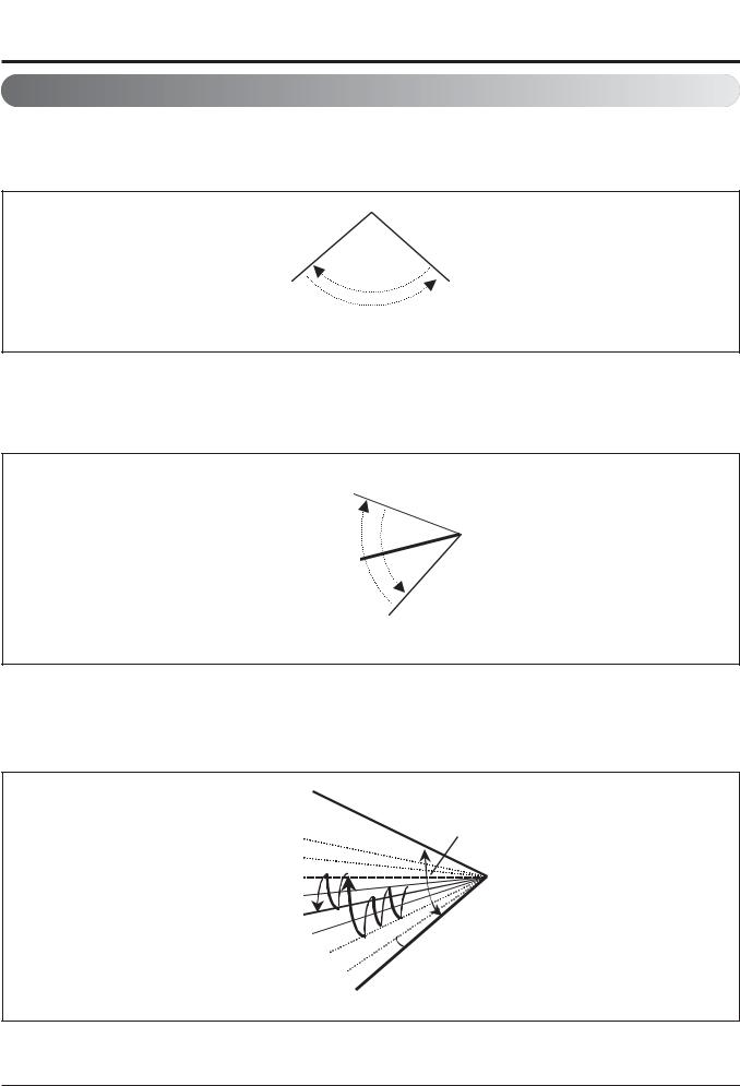
2.Air flow
2.1Auto swing (left & right)
•By the horizontal airflow direction control key input, the left/right louver automatically operates with the auto swing or it is fixed to the desired direction.
Left |
Right |
|
|
110° ~ 120°
2.2 Auto swing (up & down)
•By the auto swing key input, the upper/lower vane automatically operates with the auto swing or it is fixed to the desired direction.
Close
110° ~ 120°
Open
2.3 Chaos swing (up/down)
•By the Chaos swing key input, the upper/lower vane automatically operates with the chaos swing or it is fixed to the desired direction.
CLOSED
110~120°
Mode9 |
|
Mode8 |
|
Mode7 |
|
Mode6 |
|
Mode5 |
|
Mode4 |
|
Mode3 |
7~8° |
Mode2 |
|
OPEN
Copyright ©2012 LG Electronics. Inc. All right reserved. |
- 14 - |
Only for training and service purposes |
LGE Internal Use Only |
|

Part 2 Functions & Controls
2.4 Air flow step
•Indoor fan motor control have 6 steps.
•Air volume is controlled "SH", "H", "Med", Low" by remote controller.
•"LL" step is selected automatically in Hot start operation.
Step |
Discription |
|
|
LL |
Very low, In heating mode |
|
|
L |
Low |
|
|
M |
Med |
|
|
H |
High |
|
|
SH |
Super high |
|
|
Auto |
Chaos wind |
|
|
2.5 Chaos wind (auto wind)
• When "Auto" step selected and then operated, the high, medium, or low speed of the airflow mode is operated for 2~15 sec. randomly by the Chaos Simulation
2.6 Jet Cool Mode Operation
•While in heating mode or Fuzzy operation, the Jet Cool key cannot be input.
When it is input while in the other mode operation (cooling, dehumidification, ventilation), the Jet Cool mode is operated.
•In the Jet Cool mode, the indoor fan is operated at super-high speed for 30 min. at cooling mode operation.
•In the Jet Cool mode operation, the room temperature is controlled to the setting temperature, 18°C.
•When the sleep timer mode is input while in the Jet Cool mode operation, the Jet Cool mode has the priority.
•When the Jet Cool key is input, the upper/lower vanes are reset to those of the initial cooling mode and then operated in order that the air outflow could reach further.
Vane 2
2.7 Swirl wind Swing
•It is the function for comfort cooling/heating operation.
•The diagonal two louvers are opened the more larger than the other louvers. After one minute, it is opposite.
Vane 1 |
Vane 3 |
• Comparison of Air Flow Types |
|
|
|
|
|
|
Vane 4 |
|
|||||
4-Open (conventional) |
|
Swirl Swing (New) |
|
||||||||||
|
|
|
|
|
|
|
|
|
|
|
|
|
|
|
|
|
|
|
|
|
|
|
|
|
|
|
|
|
|
|
|
|
|
|
|
|
|
|
|
|
|
|
|
|
|
|
|
|
|
|
|
|
|
|
|
|
|
|
|
|
|
|
|
|
|
|
|
|
|
|
|
|
|
|
|
|
|
|
|
|
|
|
|
|
|
|
|
|
|
|
|
|
|
|
|
|
|
|
|
|
|
|
|
|
|
|
|
|
|
|
|
|
|
|
|
|
|
|
|
|
|
|
|
|
|
|
|
|
|
|
|
|
|
|
|
|
|
|
|
|
|
|
|
|
|
|
|
|
|
|
|
|
|
|
|
|
|
|
|
|
|
|
|
|
|
|
|
|
|
|
|
|
|
|
|
|
|
|
|
|
|
|
|
|
|
|
|
|
|
|
|
|
|
|
|
|
|
|
|
|
|
|
|
|
|
|
|
|
|
|
|
|
|
|
|
|
|
|
|
|
|
|
|
|
|
|
|
|
|
|
|
|
|
|
|
|
|
NOTE: Some Models are different by swing width and swing pattern.
Copyright ©2012 LG Electronics. Inc. All right reserved. |
- 15 - |
Only for training and service purposes |
LGE Internal Use Only |
|

Part 2 Functions & Controls
3. Air purifying
3.1 PLASMA Air Purifying System (Optional) |
||
The PLASMA Air Purifying System not only removes microscopic contaminants and dust, but also removes house |
||
mites, pollen, and pet fur to help prevent allergic diseases like asthma. This filter that can be used over and over again |
||
by simply washing with water. |
|
|
|
Dust electrode discharge |
|
Dust particles |
|
|
|
Ionizer |
Photo-Catalyst Coated Mesh |
|
+4.8KV discharge + |
|
|
+ |
+ |
Polluted Air |
Purified fresh Air |
|
|
|
+ |
|
|
+ |
Odour |
|
Generating plasma |
|
|
|
|
|
Odour molecule |
Copyright ©2012 LG Electronics. Inc. All right reserved. |
- 16 - |
Only for training and service purposes |
LGE Internal Use Only |
|

Part 2 Functions & Controls
4.Installation Functions
4.1E.S.P. (External Static Pressure) Setting (DUCT)
This is the function that decides the strength of the wind for each wind level and because this function is to make the installation easier.
•If you set ESP incorrectly, the air conditioner may malfunction.
•This setting must be carried out by a certificated-technician.
|
When pressing the |
OPER |
|
button and MODE |
|
|
1 button simultaneously for more than 3 |
|
|
seconds, the system will be entered into the |
|
|
installer setting mode. |
|
|
- After entering into the installer setting |
|
|
mode, select the E.S.P code value by |
|
|
pressing the MODEOPER |
button. |
|
* E.S.P code value : 03 |
|
|
Select the desired air flow rate with |
|
|
FAN |
|
|
2 the SPEED button. Whenever pressing |
|
|
the SPEEDFAN button, [SLo→Lo→Med→Hi→Po] will |
|
|
be indicated. |
|
FAN |
|
|
SPEED |
Select the desired air flow rate value with |
|
TEMP |
3 the temperature up(s), down(t) button. |
|
OPER |
* E.S.P value range : 0~255 |
|
MODE |
- E.S.P value will be indicated at the upper |
|
|
||
|
right section of the display window. |
|
4 When pressing the  button, currently established E.S.P value will be set up.
5 When pressing the  button and button simultaneously for more than 3 seconds after the setting has been completed, the setting mode will be released.
-If there isn’t any button input for more than 25 seconds, the installer setting mode will also be released.
•Precaution shall be taken not to alter the E.S.P value corresponded to each air flow section.
•E.S.P value can be varied according to the products.
•In the case of going to the next air flow rate stage by pressing the fan-speed button during the setup of the E.S.P value, the E.S.P value of previous air flow rate will be maintained by remembering the E.S.P value prior to the shift.
Copyright ©2012 LG Electronics. Inc. All right reserved. |
- 17 - |
Only for training and service purposes |
LGE Internal Use Only |
|

Part 2 Functions & Controls
E.S.P. setting value (reference)
Table 1
|
|
|
|
|
Static Pressure(Pa) |
|
|
||
|
|
|
|
|
|
|
|
|
|
Capacity |
Step |
CFM |
24.5 |
39.2 |
|
58.8 |
|
78.4 |
98 |
|
|
|
|
|
|
|
|
|
|
|
|
|
|
|
|
Setting Value |
|
|
|
|
|
|
|
|
|
|
|
|
|
|
HIGH |
688 |
900 |
970 |
|
1080 |
|
1190 |
1260 |
|
|
|
|
|
|
|
|
|
|
24K |
MID |
600 |
860 |
930 |
|
1050 |
|
1150 |
1230 |
|
|
|
|
|
|
|
|
|
|
|
LOW |
565 |
820 |
900 |
|
1020 |
|
1120 |
1200 |
|
|
|
|
|
|
|
|
|
|
|
HIGH |
1130 |
- |
960 |
|
1030 |
|
1090 |
1150 |
|
|
|
|
|
|
|
|
|
|
36K |
MID |
950 |
- |
850 |
|
960 |
|
1020 |
1090 |
|
|
|
|
|
|
|
|
|
|
|
LOW |
706 |
- |
760 |
|
850 |
|
950 |
1000 |
|
|
|
|
|
|
|
|
|
|
[ Notes ]
1.To get the desired Airflow & E.S.P. combination from the table set the matching value from the table. Value other than that in table will not give the combinations of airflow & E.S.P. which are mentioned in the table.
2.Table data is based at 230V. According to the fluctuation of voltage, air flow rate varies.
Copyright ©2012 LG Electronics. Inc. All right reserved. |
- 18 - |
Only for training and service purposes |
LGE Internal Use Only |
|

Part 2 Functions & Controls
4.2 E.S.P. (External Static Pressure) Setting (Cassette)
This function is applied to only duct type. Setting this in other cases will cause malfunction.
Press |
button for 4 seconds to enter the installer |
|
1 setting mode until timer segment displays “01:01”. |
||
If pressing |
button repeatedly, it moves to static pressure |
|
2 selection menu as picture below.
|
|
|
|
|
|
|
|
|
|
|
|
|
|
|
|
|
|
|
|
|
|
|
|
|
|
|
|
|
|
|
|
|
|
|
|
|
|
|
|
|
|
|
|
|
|
|
|
|
|
|
|
|
|
|
|
|
|
|
|
|
|
|
|
|
|
|
|
|
|
|
|
|
|
|
|
|
|
|
|
|
|
|
|
|
|
|
|
|
|
|
|
|
|
|
|
|
|
|
|
|
|
|
|
3 Select static pressure by pressing |
button. |
|||||||||||
(01:V-H, 02:F-H, 03:V-L, 04:F-L) |
|
|||||||||||
Function Code |
Pressure |
4 Press |
button to save. |
5 Pressing |
button will exit settings mode. |
After setup, it automatically gets out of setup mode if there is no button input for 25 seconds.
When exiting without pressing set button, the manipulated value is not reflected.
<Static Pressure Setting Table>
|
Pressure selection |
|
Function |
||
|
Zone state |
|
ESP standard value |
||
|
|
|
|
||
01 |
|
V-H |
Variable |
|
High |
02 |
|
F-H |
Fixed |
|
High |
|
|
|
|
|
|
03 |
|
V-L |
Variable |
|
Low |
|
|
|
|
|
|
04 |
|
F-L |
Fixed |
|
Low |
|
|
|
|
|
|
Copyright ©2012 LG Electronics. Inc. All right reserved. |
- 19 - |
Only for training and service purposes |
LGE Internal Use Only |
|

Part 2 Functions & Controls
This is the function that decides the strength of the wind for each wind level and because this function is to make the installation easier.
•If you set ESP incorrectly, the air conditioner may malfunction.
•This setting must be carried out by a certificated-technician.
|
If pressing |
button long for 3 seconds, it enters into remote |
||
1 controller setter setup mode. |
|
|
||
|
- If pressing once shortly, it enters into user setup mode. |
|||
|
Please press more than 3 seconds for sure. |
|
||
|
If entering into ESP setup mode by using |
button, it indicates as |
||
2 the picture below. |
|
|
||
|
|
ESP step |
|
|
|
|
Function Code |
ESP value |
|
3 |
Select ESP fan step by pressing |
|
button. (01: very low, 02: low, |
|
03: medium, 04: high, 05: very high) |
|
|||
Function code, |
|
|
|
|
ESP code |
|
|
|
|
ESP value |
|
|
|
|
4 |
Move to ESP value setting by pressing |
button. |
(It is 000 when delivering |
|
from the warehouse.)
5 Press 


 button to setup ESP value.
(It is possible to setup ESP value from 1 to 255, and 1 is the smallest and 255 is the biggest.)
• When setting ESP value on the product without very weak wind or power wind function, it may not work.
6 |
Select ESP fan step again by using |
button and setup ESP value, as |
|
No. 4 and 5, that corresponds each wind flow |
|||
7 |
Press |
button to save. |
|
8 |
Press |
button to exit. |
|
After setup, it automatically gets out of setup mode if there is no button |
|||
|
input for 25 seconds. |
|
|
|
When exiting without pressing set button, the manipulated value is not |
||
|
reflected. |
|
|
Function code, ESP code |
|
|
|
ESP value |
|
|
|
•Please be careful not to change the ESP value for each fan step.
•It does not work to setup ESP value for very low/power step for some products.
•ESP value is available for specific range belongs to the product.
Copyright ©2012 LG Electronics. Inc. All right reserved. |
- 20 - |
Only for training and service purposes |
LGE Internal Use Only |
|
Part 2 Functions & Controls
5. Reliability
5.1 Hot start
• When heating is started, the indoor fan is stopped or very slow to prevent the cold air carry out
• When the temp. of heat exchanger reach 30°C(model by model), indoor fan is started.
5.2 Self-diagnosis Function
• The air conditioner installed can self-diagnosed its error status and then transmits the result to the central control. Therefore, a rapid countermeasure against failure of the air conditioner allows easy management and increases the usage life of air conditioner.
• Refer to trouble shooting guide.
5.3 Soft dry operation
•When the dehumidification operation input by the remote control is received, the intake air temperature is detected and the setting temp is automatically set according to the intake air temperature.
Intake air Temp. |
Setting Temp. |
26°C ≤ intake air temp. |
25°C |
|
|
24°C ≤ intake air temp.< 26°C |
intake air temp. -1°C |
|
|
22°C ≤ intake air temp. < 24°C |
intake air temp. -0.5°C |
|
|
18°C ≤ intake air temp. < 22°C |
intake air temp. |
|
|
intake air temp. < 18°C |
18°C |
•While compressor off, the indoor fan repeats low airflow speed and stop.
•While the intake air temp is between compressor on temp. and compressor off temp., 10-min dehumidification operation and 4-min compressor off repeat.
Compressor ON Temp. ‘ Setting Temp+0.5°C Compressor OFF Temp. ‘ Setting Temp-0.5°C
•In 10-min dehumidification operation, the indoor fan operates with the low airflow speed.
Copyright ©2012 LG Electronics. Inc. All right reserved. |
- 21 - |
Only for training and service purposes |
LGE Internal Use Only |
|

Part 2 Functions & Controls
6.Convenience Functions & Controls
6.1Cooling & heating Operations
6.1.1 Cooling Mode
•Operating frequency of compressor depends on the load condition, like the difference between the room temp. and the set temp., frequency restrictions.
•If the compressor operates at some frequency, the operating frequency of compressor cannot be changed within 30 seconds. ( not emergency conditions)
•Compressor turned off when
-intake air temperature is in between ±0.5°C of the setting temp. limit for three minutes continuously.
-intake air temperature reaches below 1.0°C of the temperature of setting temp..
•Compressors three minutes time delay.
-After compressor off, the compressor can restart minimum 3 minutes later.
6.1.2 Heating Mode
•Operating frequency of compressor depend on the load condition, The difference between the room temp. and set temp., frequency restrictions.
•If compressor operates at some frequency, the operating frequency of compressor cannot be changed within 30 seconds.
•Condition of compressor turned off
-When intake air temperature reaches +4°C above the setting temperature.
•Condition of compressor turned on
-When intake air temperature reaches +2°C above the setting temperature.
*Condition of indoor fan turned off
-While in compressor on : indoor pipe temp. < 20°C
-While in compressor off : indoor pipe temp. < 30°C
•While in defrost control, between the indoor and outdoor fans are turned off.
•Compressor 2minutes delay
-After compressor off, the compressor can restart minimum 2 minutes later.
NOTE: Some Models are different by temperature of thermo ON/OFF.
CST/Duct/CVT type indoor unit matched with |
CST/ Duct/CVT type indoor unit |
|
matched with Single Outdoor unit/Multi |
||
Universal Outdoor unit |
||
Outdoor unit/Multi V Outdoor unit |
||
|
||
|
|
|
Thermo ON : +2 °C above setting temp. |
Thermo ON : Setting temp. |
|
Thermo OFF : +4 °C above setting temp. |
Thermo OFF : +3 °C above setting temp. |
|
|
|
Copyright ©2012 LG Electronics. Inc. All right reserved. |
- 22 - |
Only for training and service purposes |
LGE Internal Use Only |
|
Part 2 Functions & Controls
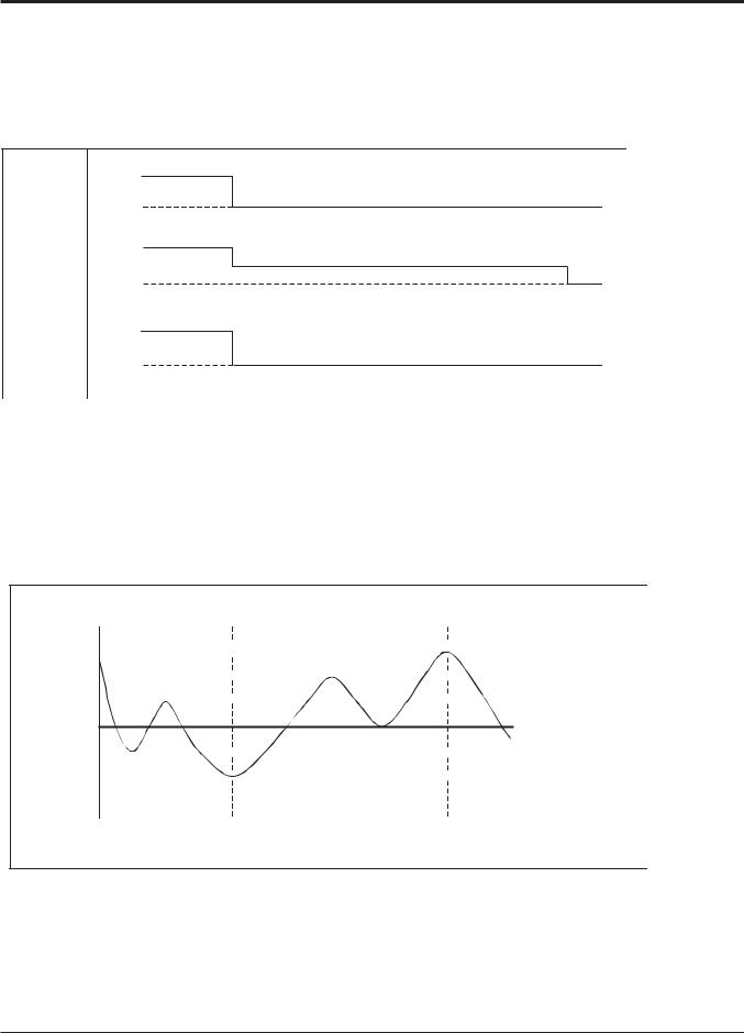
6.2 Auto cleaning operation
•Function used to perform Self Cleaning to prevent the Unit from Fungus and bad odor.
•Used after the Cooling Operation before turning the unit off, clean the Evaporator and keep it dry for the next operation.
•The function is easy to operate as it is accessed through the Remote controller.
Unit |
ON |
|
(Cooling Only) |
|
|
|
|
Operation |
OFF |
|
|
|
|
|
|
Indoor |
ON |
|
|
|
|
|
|
Fan |
OFF |
|
|
|
Setting step |
L Low |
OFF |
ON
Comp.
OFF
Setting step
6.3 Auto changeover operation
•The air conditioner changes the operation mode automatically to keep indoor temperature.
•When room temperature vary over ±2°C with respect to setting temperature, air conditioner keeps the room temperature in ±2°C with respect to setting temperature by auto change mode.
+4°C  Switching point +2°C
  Heating thermo off
+0.5°C 
SET Temp.
-0.5°C  Cooling thermo off -2°C
  Switching point
Cooling |
Heating operation |
Cooling |
operation |
|
operation |
6.4 Auto restart Operation
•Whenever there is electricity failure to the unit, and after resumption of the power, unit will start in the same mode prior to the power failure. Memorized condition are on / off condition, operating mode (cooling/ heating), set temperature and fan speed. The unit will memorize the above conditions and start with same memorized condition.
Copyright ©2012 LG Electronics. Inc. All right reserved. |
- 23 - |
Only for training and service purposes |
LGE Internal Use Only |
|

Part 2 Functions & Controls
6.5 Child Lock Function
It is the function to use preventing children or others from careless using.
FAN |
SPEED |
TEMP |
OPER |
MODE |
1 During the operation, when pressing the  button and SPEEDFAN button for approx. 3 seconds, the ‘Child Lock’ Function can be used.
-At the time of initial setting of the ‘Child Lock’, the ‘CL’ Will be indicated approx. 3 seconds at the temperature Display section before resuming to the previous mode.
After the setting of the ‘CL’, if another button is setup, the button can not be recognized as the ‘CL’ is indicated at the temperature display section for approx. 3 seconds.
2 If the ‘CL’ function is wanted to be used under the operation standby state, press the  button and
  Button for approx.
3 seconds under the standby mode state and the system will be the ‘CL’ state.
3 As for the releasing method, when pressing the  Button and
  button for approx. 3 seconds, the ‘CL’ function can be released.
It is the function to use preventing children or others from careless using.
1 Press 
 button repeatedly until the
  is flashing.
2 If moving to 'setup' icon area by using 


 button, 'setup' icon blinks, and child lock function is setup if pressing


 button at that time.
3 When cancelling lock function, if moving to 'cancel' icon by pressing 


 button and then, pressing


 button, child lock function is
cancelled.
4 Press 


 button to exit.
After setup, it automatically gets out of setup mode if there is no button input for 25 seconds.
When exiting without pressing set button, the manipulated value is not reflected.
Copyright ©2012 LG Electronics. Inc. All right reserved. |
- 24 - |
Only for training and service purposes |
LGE Internal Use Only |
|

Part 2 Functions & Controls
6.6 Forced operation
•To operate the appliance by force in case when the remote control is lost, the forced operation selection switch is on the main unit of the appliance, and operate the appliance in the standard conditions.
•The operating condition is set according to the outdoor temp. and intake air temperature as follows.
Indoor temp. |
Operating Mode |
Setting temp. |
Setting speed of |
|
indoor fan |
||||
|
|
|
||
|
|
|
|
|
over 24°C |
Cooling |
22°C |
|
|
|
|
|
High speed |
|
21~24°C |
Healthy Dehumidification |
23°C |
||
|
|
|
|
|
below 21°C |
Heating |
24°C |
|
|
|
|
|
|
•The unit select the last operation mode in 3 hours.
•Operating procedures when the remote control can't be used is as follows :
-The operation will be started if the ON/OFF button is pressed.
-If you want to stop operation, re-press the button.
Copyright ©2012 LG Electronics. Inc. All right reserved. |
- 25 - |
Only for training and service purposes |
LGE Internal Use Only |
|
Part 2 Functions & Controls
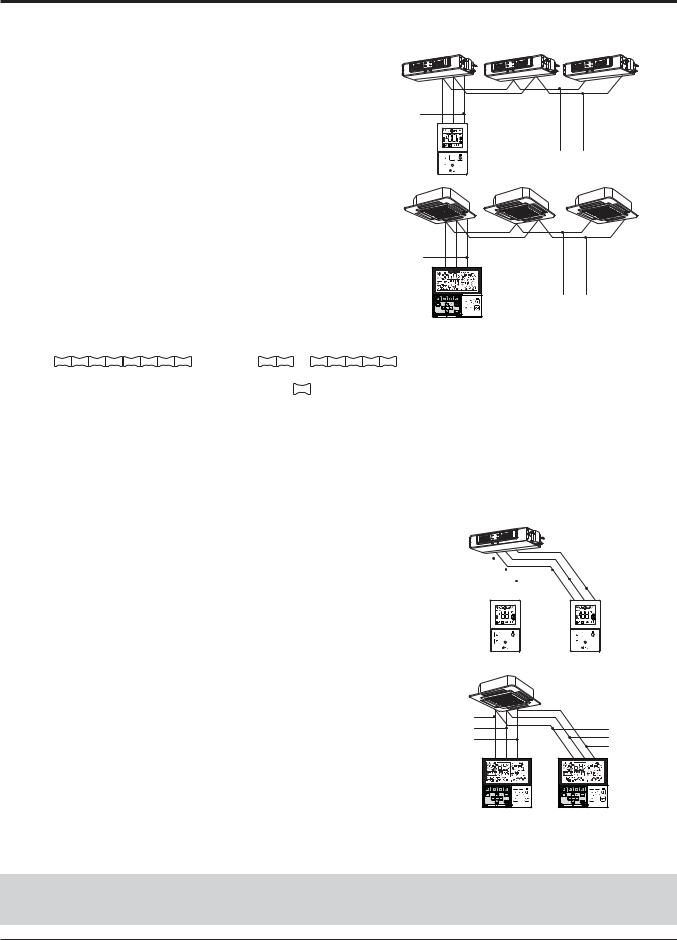
6.7 Group Control
1.When installing more than 2 units of air conditioner to one wired remote controller, please connect as the right figure.
•If it is not event communication indoor unit, set the unit as slave.
•Check for event communication through the product manual.
When controlling multiple indoor units with event communication function with one remote controller, you must change the master/slave setting from the indoor unit.
-Indoor units, the master/slave configuration of the product after completion of indoor unit power ʻOFFʼ and then ʻONʼ the power after 1 minutes elapsed sign up.
-For ceiling type cassette and duct product group, change the switch setting of the indoor PCB.
GND  Signal wire
12V
SPEED |
GND |
Signal wire |
FAN |
|
|
TEMP |
|
|
|
OPER |
|
|
MODE |
|
GND  Signal wire
12V
GND Signal wire
|
|
|
|
|
|
|
|
|
|
|
|
|
|
|
|
|
|
|
|
|
|
|
|
|
|
|
|
|
|
|
|
|
|
|
|
|
|
|
|
|
|
|
|
|
|
|
|
|
|
|
|
|
|
|
|
|
|
|
|
|
|
|
|
|
|
|
|
|
|
1 |
2 |
3 |
|
4 |
|
5 |
|
6 |
|
7 |
|
8 |
|
|
1 |
2 |
3 |
|
4 |
|
5 |
|
6 |
|
7 |
|
8 |
|
||||||
|
|
#3 switch OFF: Master |
|
|
|
|
|
|
#3 switch ON: Slave |
|
|
|||||||||||||||||||||||
|
|
(Factory default setting) |
|
|
|
|
|
|
|
|
|
|
|
|
|
|
|
|
|
|
|
|
||||||||||||
-For wall-mount type and stand type product, change the master/slave setting with the wireless remote controller. (Refer to wireless remote controller manual for detail)
ηWhen installing 2 remote controllers to one indoor unit with event communication function, set the master/slave of the remote controller. (Refer to remote controller master/slave selection)
When controlling the group, some functions excluding basic operation setting, fan level Min/Mid/Max, remote controller lock setting and time setting may be limited.
2.When installing more than 2 wired remote controllers to one air conditioner, please connect as the right picture.
GND |
|
|
|
|
|
|
|
|
|
|
|
|
|
|
|
GND |
|
|
|
|
|
|
|
|
|
|
|
|
|
|
|||
Signal wire |
|
|
|
|
|
|
|
|
|
|
|
|
|
|
||
12V |
|
|
|
|
|
|
|
|
|
|
|
|
|
|
|
Signal wire |
|
|
|
|
|
|
|
|
|
|
|
|
|
|
|
||
|
|
|
|
|
|
|
|
|
|
|
|
|
|
12V |
||
|
|
|
|
|
|
|
|
|
|
|
|
|
|
|
|
|
|
B |
Y |
R |
|
|
B Y R |
||||||||||
|
|
|
|
|
|
|
|
|
|
|
|
|
|
|
|
|
|
|
|
|
|
|
|
|
|
|
|
|
|
|
|
|
|
•When installing more than 2 units of wired remote controller to one air conditioner, set one wired remote controller as master and the others all as slaves, as shown in the right picture.
•You cannot control the group as shown in the right for some products.
•Refer to the product manual for more detail.
FAN
SPEED
TEMP
OPER
MODE
MASTER
GND Signal wire 12V
B Y R |
MASTER |
FAN
SPEED
TEMP
OPER
MODE
SLAVE
GND Signal wire 12V
B |
Y R |
|
SLAVE |
<When simultaneously connecting 2 sets of wired remote controller>
•When controlling in groups, set the master/slaver of the remote controller. Refer to Installer setting section on how to set master/slave for more detail.
Copyright ©2012 LG Electronics. Inc. All right reserved. |
- 26 - |
Only for training and service purposes |
LGE Internal Use Only |
|

Part 2 Functions & Controls
6.8 Sleep Timer Operation
•When the sleep time is reached after <1,2,3,4,5,6,7,0(cancel) hr> is input by the remote control while in appliance operation, the operation of the appliance stops.
•While the appliance is on pause, the sleep timer mode cannot be input.
•While in cooling mode operation, 30 min later since the start of the sleep timer, the setting temperature increases by 1°C. After another 30 min elapse, it increases by 1°C again.
•When the sleep timer mode is input while in cooling cycle mode, the airflow speed of the indoor fan is set to the low.
•When the sleep timer mode is input while in heating cycle mode, the airflow speed of the indoor fan is set to the medium.
6.9 Timer(On/Off)
6.9.1 On-Timer Operation
•When the set time is reached after the time is input by the remote control, the appliance starts to operate.
•The timer LED is on when the on-timer is input. It is off when the time set by the timer is reached.
•If the appliance is operating at the time set by the timer, the operation continues.
While in Fuzzy operation, the airflow speed of the indoor fan is automatically selected according to the temperature.
6.9.2 Off-Timer Operation
•When the set time is reached after the time is input by the remote control, the appliance stops operating.
•The timer LED is on when the off-timer is input. It is off when the time set by the timer is reached.
•If the appliance is on pause at the time set by the timer, the pause continues.
Copyright ©2012 LG Electronics. Inc. All right reserved. |
- 27 - |
Only for training and service purposes |
LGE Internal Use Only |
|
 Loading...