


website http://www.lgservice.com
LG
LG Room
Air Conditioner
SERVICE MANUAL
MODEL: LWHD1800HR, LWHD2400HR
LWHD1807HR, LWHD2400HRY7
CAUTION
•BEFORE SERVICING THE UNIT, READ THE SAFETY PRECAUTIONS IN THIS MANUAL.
•ONLY FOR AUTHORIZED SERVICE PERSONNEL.

Air Conditioner Service Manual |
|
TABLE OF CONTENTS |
|
Safety Precautions.......................................................................................................................................... |
3 |
Dimensions...................................................................................................................................................... |
5 |
Product Specifications ................................................................................................................................... |
6 |
Installation ....................................................................................................................................................... |
8 |
How to Install the Unit ................................................................................................................................ |
8 |
How to use the Reversible Inlet grille ......................................................................................................... |
8 |
Window Requirements ............................................................................................................................... |
9 |
Installation Kits Contents (some models including installation kit) ........................................................... |
10 |
Suggested tool Requirements.................................................................................................................. |
10 |
Cabinet Installation................................................................................................................................... |
11 |
Operation ....................................................................................................................................................... |
13 |
Disassembly instructions............................................................................................................................. |
14 |
Mechanical parts ...................................................................................................................................... |
14 |
Air Handling Parts .................................................................................................................................... |
15 |
Electrical Parts ......................................................................................................................................... |
16 |
Refrigeration cycle ................................................................................................................................... |
19 |
Schematic Diagram....................................................................................................................................... |
22 |
Troubleshooting guide.................................................................................................................................. |
23 |
Piping System .......................................................................................................................................... |
23 |
Troubleshooting guide .............................................................................................................................. |
24 |
Room Air Conditioner Voltage Limits........................................................................................................ |
26 |
Exploded View............................................................................................................................................... |
28 |
Replacement Parts List ................................................................................................................................ |
29 |
2 Room Air Conditioner

Safety Precautions
Safety Precautions
To prevent injury to the user or other people and property damage, the following instructions must be followed.
■Incorrect operation due to ignoring instruction will cause harm or damage. The seriousness is classified by the following indications.
 WARNING This symbol indicates the possibility of death or serious injury.
 CAUTION This symbol indicates the possibility of injury or damage to property only.
■ Meanings of symbols used in this manual are as shown below.
Be sure not to do.
Be sure to follow the instruction.
 WARNING
■ Installation
Do not use damaged power cord plugs, or a loose socket.
Always use the power plug and socket with the ground terminal.
• There is risk of fire or electric shock. |
• There is risk of electric shock. |
Service Manual 3
Safety Precautions
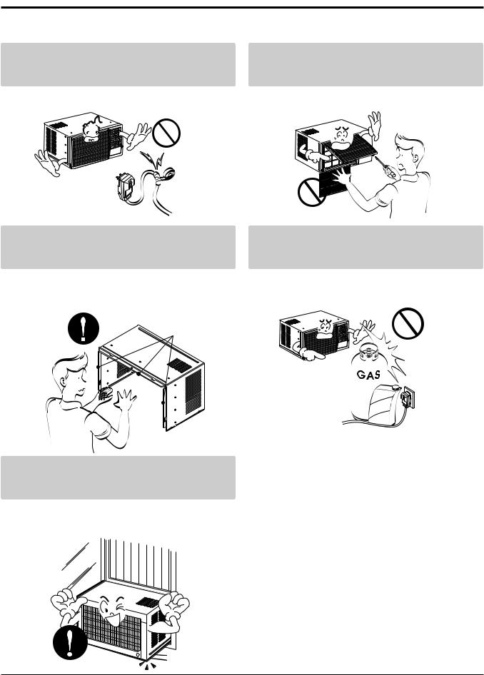
Do not modify or extend the power cord.
Do not install, remove, or re-install the unit by yourself(customer).
• There is risk or fire or electric shock. |
• There is risk of fire, electric shock, explosion, or injury. |
Be cautious when unpacking and installing the product.
Do not store or use flammable gas or combustibles near the air conditioner.
• Sharp edges could cause injury. Be especially careful |
• There is risk of fire or failure of product. |
Sharp edges
Gasolin
Be sure the installation area does not deteriorate with age.
•If the base collapses, the air conditioner could fall with it, causing property damage, product failure, and personal injury.
4 Room Air Conditioner

Dimensions
Dimensions

 Symbols
 Used
Used in this Manual


This symbol alerts you to the risk of electric shock.
This symbol alerts you to hazards that could cause harm to the air conditioner.
NOTICE This symbol indicates special notes.

 Outside
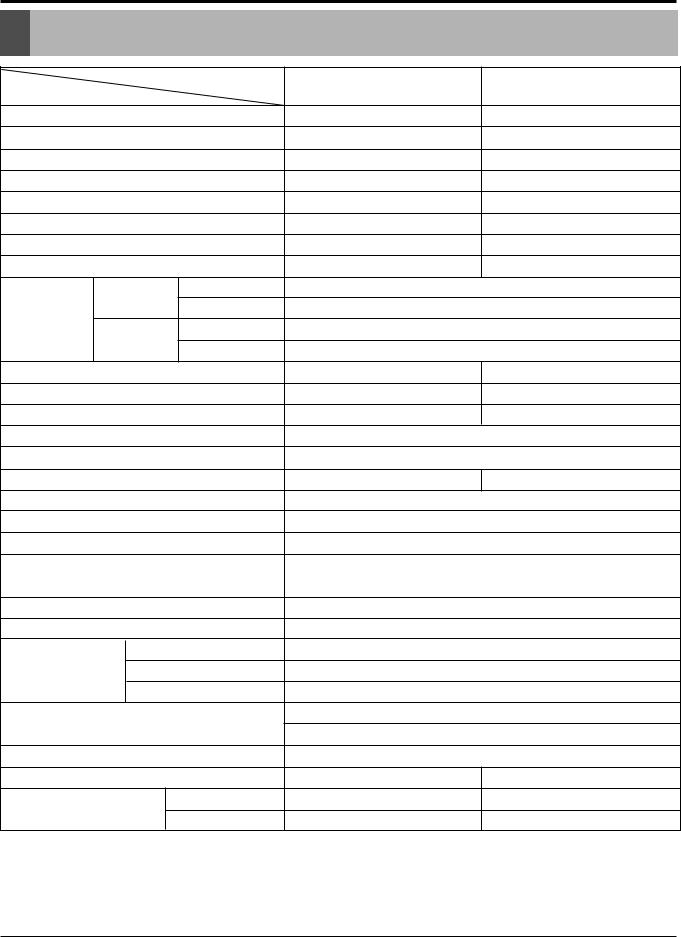
 Dimensions


D
W
H
|
Model |
LWHD1800HR |
LWHD2400HR |
Dimension |
|
||
|
|
|
|
W |
mm(inch) |
660 (26) |
660 (26) |
H |
mm(inch) |
428 (16 27/32) |
428 (16 27/32) |
D |
mm(inch) |
675 (26 9/16) |
770 (30 5/16) |
|
|
|
|
Service Manual 5

Specfications
Product Specifications
|
MODELS |
LWHD1800HR |
LWHD2400HR |
|
ITEMS |
|
|||
|
|
|
||
POWER SUPPLY |
|
1Ø, 208/230V, 60Hz |
1Ø, 208/230V, 60Hz |
|
COOLING CAPACITY |
(Btu/h) |
17,500/18,000 |
23,00/23,500 |
|
INPUT |
(W) |
1,800/1,850 |
2,700/2,760 |
|
RUNNING CURRENT |
(A) |
9.0/8.3 |
13.2/12.2 |
|
E.E.R |
(BTU/W.h) |
9.7 |
8.5 |
|
HEATING CAPACITY |
(Btu/h) |
9,800/12,00 |
9,400/11,600 |
|
INPUT |
(W) |
3,100/3,670 |
3,750/3,770 |
|
RUNNING CURRENT |
(A) |
15.0/16.0 |
15.0/16.0 |
|
|
INDOOR(°C) |
26.7 (DB)* |
19.4 (WB)** |
|
COOLING |
35 (DB)* |
23.9 (WB)** |
||
OPERATING |
OUTDOOR(°C) |
|||
CONDITION |
INDOOR(°C) |
21.1 (DB)* |
15.6 (DB)** |
|
HEATING |
8.3 (DB)* |
6.1 (DB)** |
||
|
OUTDOOR(°C) |
|||
REFRIGERANT (R-22) CHARGE |
710(25.0 oz) |
880(31.0 oz) |
||
EVAPORATOR |
|
3ROW 18STACKS |
4ROW 18STACKS |
|
CONDENSER |
|
2ROW 18STACKS,L-BENDING TYPE |
3ROW 19STACKS |
|
FAN, INDOOR |
|
BLOWER |
||
FAN, OUTDOOR |
|
PROPELLER TYPE FAN WITH SLINGER-RING |
||
FAN SPEEDS, FAN/COOLING/HEATING |
1 / 2 / 2 |
1 / 2 / 2 |
||
FAN MOTOR |
|
6 POLES |
||
OPERATION CONTROL |
TOUCH PANEL |
|||
ROOM TEMP. CONTROL |
THERMISTOR |
|||
AIR DIRECTION CONTROL |
VERTICAL LOUVER(RIGHT&LEFT) |
|||
HORIZONTAL LOUVER(UP&DOWN) |
||||
|
|
|||
CONSTRUCTION |
|
SLIDE IN-OUT CHASSIS |
||
ELECTRIC HEATER |
|
3.5KW, 230V |
||
|
COMPRESSOR |
INTERNAL OVERLOAD PROTECTOR |
||
PROTECTOR |
FAN MOTOR |
INTERNAL THERMAL PROTECTOR |
||
|
ELECTRIC HEATER |
FUSE LINK, BIMETAL THERMOSTAT |
||
POWER CORD |
|
1.6m(3 WIRE WITH GROUNDING) |
||
|
ATTACHMENT PLUG(CORD-CONNECTED TYPE) |
|||
|
|
|||
DRAIN SYSTEM |
|
DRAIN PIPE OR SPLASHED BY FAN SLINGER |
||
NET WEIGHT |
(lbs/kg) |
123/56 |
143/65 |
|
OUTSIDE DIMENSION |
(inch) |
26 X 16 27/32 X 26 9/16 |
26 X 16 27/32 X 30 5/16 |
|
(W x H x D) |
(mm) |
660 X 428 X 675 |
660 X 428 X 770 |
|
* DB:Dry Bulb
**WB:Wet Bulb
NOTE: Please refer to Label Quality on the produst since this specification may be changed for improving performance.
6 Room Air Conditioner
Specfications
Product Specifications
|
MODELS |
LWHD1807HR |
LWHD2400HRY7 |
|
ITEMS |
|
|||
|
|
|
||
POWER SUPPLY |
|
1Ø, 208/230V, 60Hz |
1Ø, 208/230V, 60Hz |
|
COOLING CAPACITY |
(Btu/h) |
17,500/18,000 |
23,00/23,500 |
|
INPUT |
(W) |
1,800/1,850 |
2,700/2,760 |
|
RUNNING CURRENT |
(A) |
9.0/8.3 |
13.2/12.2 |
|
E.E.R |
(BTU/W.h) |
9.7 |
8.5 |
|
HEATING CAPACITY |
(Btu/h) |
9,800/12,00 |
9,400/11,600 |
|
INPUT |
(W) |
3,100/3,670 |
3,750/3,770 |
|
RUNNING CURRENT |
(A) |
15.0/16.0 |
15.0/16.0 |
|
|
INDOOR(°C) |
26.7 (DB)* |
19.4 (WB)** |
|
COOLING |
35 (DB)* |
23.9 (WB)** |
||
OPERATING |
OUTDOOR(°C) |
|||
CONDITION |
INDOOR(°C) |
21.1 (DB)* |
15.6 (DB)** |
|
HEATING |
8.3 (DB)* |
6.1 (DB)** |
||
|
OUTDOOR(°C) |
|||
REFRIGERANT (R-22) CHARGE |
810(28.6oz) |
1040(36.7oz) |
||
EVAPORATOR |
|
3ROW 18STACKS |
3ROW 15STACKS |
|
CONDENSER |
|
2ROW 18STACKS,L-BENDING TYPE |
2ROW 16STACKS |
|
FAN, INDOOR |
|
BLOWER |
||
FAN, OUTDOOR |
|
PROPELLER TYPE FAN WITH SLINGER-RING |
||
FAN SPEEDS, FAN/COOLING/HEATING |
1 / 2 / 2 |
1 / 2 / 2 |
||
FAN MOTOR |
|
6 POLES |
||
OPERATION CONTROL |
TOUCH PANEL |
|||
ROOM TEMP. CONTROL |
THERMISTOR |
|||
AIR DIRECTION CONTROL |
VERTICAL LOUVER(RIGHT&LEFT) |
|||
HORIZONTAL LOUVER(UP&DOWN) |
||||
|
|
|||
CONSTRUCTION |
|
SLIDE IN-OUT CHASSIS |
||
ELECTRIC HEATER |
|
3.5KW, 230V |
||
|
COMPRESSOR |
INTERNAL OVERLOAD PROTECTOR |
||
PROTECTOR |
FAN MOTOR |
INTERNAL THERMAL PROTECTOR |
||
|
ELECTRIC HEATER |
FUSE LINK, BIMETAL THERMOSTAT |
||
POWER CORD |
|
1.6m(3 WIRE WITH GROUNDING) |
||
|
ATTACHMENT PLUG(CORD-CONNECTED TYPE) |
|||
|
|
|||
DRAIN SYSTEM |
|
DRAIN PIPE OR SPLASHED BY FAN SLINGER |
||
NET WEIGHT |
(lbs/kg) |
123/56 |
143/65 |
|
OUTSIDE DIMENSION |
(inch) |
26 X 16 27/32 X 26 9/16 |
26 X 16 27/32 X 30 5/16 |
|
(W x H x D) |
(mm) |
660 X 428 X 675 |
660 X 428 X 770 |
|
* DB:Dry Bulb
**WB:Wet Bulb
NOTE: Please refer to Label Quality on the produst since this specification may be changed for improving performance.
7 Room Air Conditioner
Installation
INSTALLATION

 How
How to
to Install
 the
the unit
unit


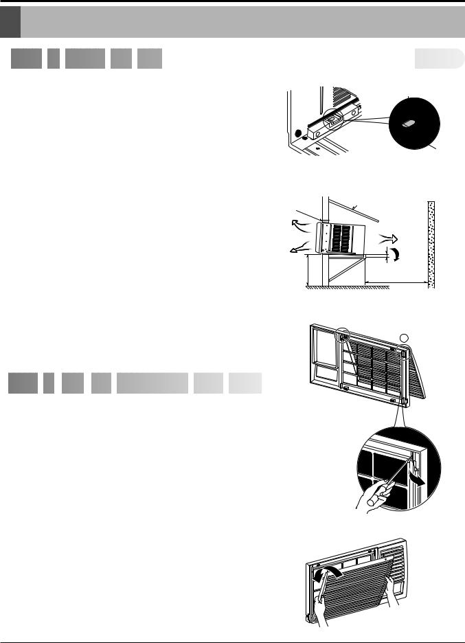
1.To avoid vibration and noise, make sure the unit is installed securely and firmly.
2.Install the unit where the sunlight does not shine directly on the unit.
If the unit receives direct sunlight, build an awning to shade the cabinet.
3.There should be no obstacle, like a fence, within 20" which might restrict heat radiation from the condenser.
4.To prevent reducing performance, install the unit so that louvers of the cabinet are not blocked.
5.Install the unit a little obliquely outward not to leak the condensed water into the room (about 1/2" or 1/4 bubble with level).
6.Install the unit with its bottom portion 30~60" above the floor level.
7.Stuff the foam between the top of the unit and the wall to prevent air and insects from getting into the room.
8.The power cord must be connected to an independent circuit. The green wire must be grounded.
1/4 Bubble
Level
AWNING FENCE
FOAM
HEAT
RADIATION
COOLED
AIR
3060"- |
About 1/2" |
|
Over 20" |
||
|
9.Connect the drain tube to the base pan hole in the rear side if you need to drain (consult a dealer).
Plastic hose or equivalent may be connected to the drain tube.


 How
How
 to
to
 use
use
 the
the
 Reversible
 Inlet
Inlet
 grille


The grille is designed to clean the filter both upward and downward.
A.BEFORE ATTACHING THE FRONT GRILLE TO THE CABINET, IF YOU WANT TO PULL OUT THE FILTER UPWARD;
1.Open the inlet grille slightly (a).
2.Turn inside out the front grille (a).
3.Disassemble the inlet grille from the front grille with separating the hinged part by inserting a straight type screw-driver tip (b).
4.Then, rotate the inlet grille 180 degrees and insert the hooks into bottom holes of the front grille.
5.Insert the filter and attach the front grille to the cabinet.
B. IF YOU WANT TO PULL OUT THE FILTER DOWNWARD;
THE GRILLE IS ALREADY DESIGNED FOR THAT WAY.
b
(a)
(b)
Service Manual 8
Installation

 Window
 Requirements


NOTICE All supporting parts should be secured to firm wood, masonry, or metal.
• WINDOW REQUIREMENTS
1.This unit is designed for installation in standard double hung windows with actual opening widths from 29" to 41". The top and bottom window sashes must open sufficiently to allow a clear vertical opening of 18" from the bottom of the upper sash to the window stool.
2.The stool offset (height between the stool and sill) must be less than 1 1/4".

 Installation
 Kits
Kits Contents
 (some
(some models including
 installation
 kit)
kit)


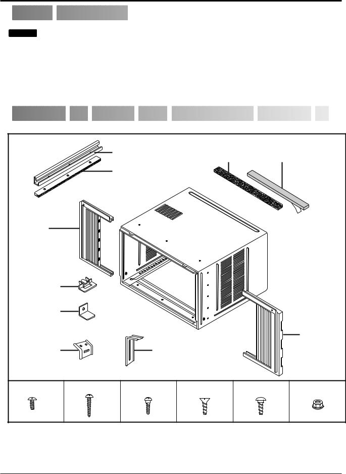
|
|
Top retainer bar |
Foam strip |
Foam-PE |
|
|
|
|
|
(Plain-Back) |
(Adhesive-Backed) |
|
|||
|
|
|
|
||||
|
|
Foam-PE |
|
|
|
|
|
|
|
(Adhesive-Backed) |
|
|
|
|
|
Left frame |
|
|
|
|
|
|
|
curtain |
|
|
|
|
|
|
|
Frame guide(2) |
|
|
|
|
|
|
|
Window locking |
|
|
|
|
|
|
|
bracket |
|
|
|
|
|
|
|
|
|
|
|
|
|
Right frame |
|
Sill bracket(2) |
|
Support bracket(2) |
|
|
curtain |
|
|
|
|
|
|
|
|||
Type A (14) |
Type B (7) |
Type C (5) |
Type D (2) |
Carriage Bolt (2) |
Lock Nut |
(4) |
|
9 Room Air Conditioner
Installation

 Suggested
 tool Requirements


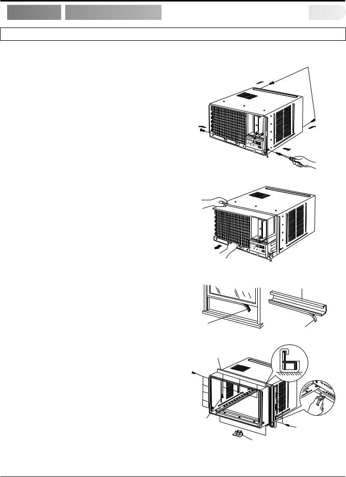
SCREWDRIVER(+, -), RULER, KNIFE, HAMMER, PENCIL, LEVEL
• PREPARATION OF CHASSIS |
Shipping screws |
1.Remove the screws which fasten the cabinet at both sides and at the back. Keep these two screws which fasten the cabinet at both sides for later use.
2.Slide the unit out from the cabinet by gripping the base pan handle and pulling forward while bracing the cabinet.
3.Cut the window sash seal to the proper length. Peel off the backing and attach the Foam-PE to the underside of the window sash.
4.Remove the backing from Foam-PE with 3 holes and attach it to the bottom of the Top retainer bar.
5.Attach the Top retainer bar onto the top of the cabinet with 3 screws (Type A).
6.Insert the Frame guides into the bottom of the cabinet.
Figure 1
Figure 2
Top retainer bar
Foam-PE |
Foam-PE |
Figure 3
7. Insert the Frame Curtain into the Top retainer bar and |
Top retainer bar |
Frame guides. |
|
8. Fasten the curtains to the unit with 10 screws (Type A) at both sides.
Screw
(Type A)
Screw(Type A)
Frame guide
Figure 4
Service Manual 10
 Loading...