


OWNER’S MANUAL
AIR CONDITIONER
Please read this manual carefully before operating your set and retain it for future reference.
TYPE:7).$/7
-/$%,3 ,7 (2 ,7 (2
|
P/NO:MFL63740301 |
www.lgappliances.com |

Window-Type Air Conditioner Owner’s Manual
TABLE OF CONTENTS
Safety Precautions.......................... |
3 |
Before Operation............................. |
7 |
Introduction .................................... |
8 |
Electrical Safety .............................. |
9 |
Installation .................................... |
11 |
Operating Instructions ................. |
16 |
Maintenance and Service ............ |
20 |

 FOR YOUR RECORDS
Write the model and serial numbers here:
Model #
Serial #
You can find them on a label on the side of each unit.
Dealer's Name
Date Purchased
■Staple your receipt to this page in the event you need it to prove date of purchase or for warranty issues.
 READ THIS MANUAL
Inside you will find many helpful hints on how to use and maintain your air conditioner properly. Just a little preventive care on your part can save you a great deal of time and money over the life of your air conditioner.
You'll find many answers to common problems in the chart of troubleshooting tips. If you review our chart of
Troubleshooting Tips first, you may not need to call for service at all.
 PRECAUTION
•Contact the authorized service technician for repair or maintenance of this unit.
•Contact the installer for installation of this unit.
•The air conditioner is not intended for use by young children or invalids without supervision.
•Young children should be supervised to ensure that they do not play with the air conditioner.
•When the power cord is to be replaced, replacement work shall be performed by authorized personnel only using only genuine replacement parts.
•Installation work must be performed in accordance with the National Electric Code by qualified and authorized personnel only.
2 Room Air Conditioner


Before Operation
Before Operation

 Preparing
 for Operation


1.Contact an installation specialist for installation.
2.Plug in the power plug properly.
3.Use a dedicated circuit.
4.Do not use an extension cord.
5.Do not start/stop operation by plugging/unplugging the power cord.
6.If the cord/plug is damaged, replace it with only an authorized replacement part.

 Usage
Usage


1.Being exposed to direct airflow for an extended period of time could be hazardous to your health. Do not expose occupants, pets, or plants to direct airflow for extended periods of time.
2.Due to the possibility of oxygen deficiency, ventilate the room when used together with stoves or other heating devices.
3.Do not use this air conditioner for non-specified special purposes (e.g. preserving precision devices, food, pets, plants, and art objects). Such usage could damage the items.

 Cleaning
 and Maintenance


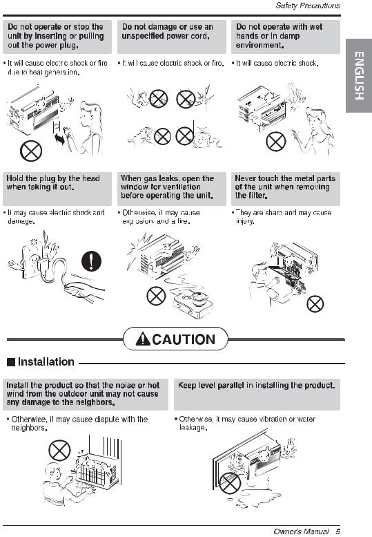
1.Do not touch the metal parts of the unit when removing the filter. Injuries can occur when handling sharp metal edges.
2.Do not use water to clean inside the air conditioner. Exposure to water can destroy the insulation, leading to possible electric shock.
3.When cleaning the unit, first make sure that the power and breaker are turned off. The fan rotates at a very high speed during operation. There is a possibility of injury if the unit’s power is accidentally triggered on while cleaning inner parts of the unit.

 Service


For repair and maintenance, contact your authorized service dealer.
ENGLISH
Owner’s Manual 7
Introduction
Introduction

 Symbols Used in
 this Manual


This symbol alerts you to the risk of electric shock.
This symbol alerts you to hazards that could cause harm to the air conditioner.
NOTICE This symbol indicates special notes.

 Features


This appliance should be installed in accordance with the National Electric Code.
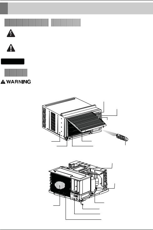
Vertical Air Deflector
(Horizontal Louver)
Horizontal Air Deflector
(Vertical Louver)
Air Discharge
Cabinet |
Air Intake(Inlet Grille) |
|
Front Grille |
Air Filter |
Remote Controller |
|
|
|
Brace
Condenser
 Base Pan
Compressor
Electric Heater
Power Cord
Control Board
Evaporator
8 Room Air Conditioner

Electrical Safety
Electrical Safety

 Electrical
 Data
Data


115V~ |
230V~ |
Power cord may include a current |
|
|
interrupter device. A test and reset button is |
|
|
provided on the plug case. The device |
|
|
should be tested on a periodic basis by first |
|
|
pressing the TEST button and then the |
|
|
RESET button. If the TEST button does not |
|
|
trip or if the RESET button will not stay |
|
|
engaged, discontinue use of the air |
|
|
conditioner and contact a qualified service |
|
|
technician. |
NOTICE
The shape may be different according to its model.
Use Wall Receptacle |
Power Supply |
||
|
|
|
|
|
|
|
|
Standard 125V, 3-wire grounding |
|
||||
receptacle rated 15A, 125V AC |
Use 15 AMP. time |
||||
|
|
|
|
|
delay fuse or 15 AMP. |
|
|
|
|
|
|
|
|
|
|
|
circuit breaker. |
|
|
|
|
|
|
Standard 250V, 3-wire grounding receptacle rated 15A, 250V AC
Use 20 AMP. time delay fuse or 20 AMP.
circuit breaker.
Standard 250V, 3-wire grounding receptacle rated 20A, 250V AC
NOTICE
DO NOT USE AN EXTENSION CORD on 230, 208, and 230/208 Volt units.
All wiring should be made in accordance with local electrical codes and regulations.
Aluminum house wiring may pose special problems. Consult a qualified electrician.
Never push the test button during operation
Otherwise this plug can damaged.
This device contains chemical, including lead, known to the State of California to cause cancer, and birth defects or other reproductive harm.
Wash hands after handling.
Do not remove, modify or immerse this plug. If this device trips, the cause it to be corrected before further use.
The conductors inside this cord are surrounded by shields, which monitor leakage current.
These shields are not grounded.
<
Periodically examine the cord for any damage. Do not use this product in the event the shields become exposed. Avoid shock hazard, this unit can not be user serviced opening the tamper resistant. Sealed portion of the unit voids all warranties and performance claims. This unit not intended for use as an on-off switch.
ENGLISH
Owner’s Manual 9

Electrical Safety

 Electrical
 Safety


IMPORTANT
(PLEASE READ CAREFULLY)
FOR THE USER'S PERSONAL SAFETY, THIS APPLIANCE MUST BE PROPERLY GROUNDED
DO NOT CUT OR REMOVE THE THIRD (GROUND) PRONG FROM THE POWER PLUG.
A.SITUATIONS WHEN THE APPLIANCE WILL BE DISCONNECTED OCCASIONALLY:
The power cord of this appliance is equipped with a three-prong (grounding) plug. Use this with a standard three-slot (grounding) wall power outlet to minimize the hazard of electric shock. The customer should have the wall receptacle and circuit checked by a qualified electrician to make sure the receptacle is properly grounded.
Because of potential safety hazards, we strongly discourage the use of an adapter plug. However, if you wish to use an adapter, a TEMPORARY CONNECTION may be made. Use UL-listed adapter, available from most local hardware stores.
The large slot in the adapter must be aligned with the large slot in the receptacle to assure a proper polarity connection.
:Attaching the adapter ground terminal to the wall receptacle cover screw does not ground the appliance unless the cover screw is metal, and not insulated, and the wall receptacle is grounded through the house wiring. The customer should have the circuit checked by a qualified electrician to make sure the receptacle is properly grounded.
Disconnect the power cord from the adapter, using one hand on each. Otherwise, the adapter ground terminal might break. DO NOT USE the appliance with a broken adapter plug.
B.SITUATIONS WHEN THE APPLIANCE WILL BE DISCONNECTED OFTEN.
Do not use an adapter plug in these situations. Unplugging the power cord frequently can lead to an eventual breakage of the ground terminal. The wall power outlet should be replaced by a three-slot (grounding) outlet instead.
USE OF EXTENSION CORDS
Because of potential safety hazards, we strongly discourage the use of an extension cord. However, if you wish to use an extension cord, use a CSA certified/UL-listed 3-wire (grounding) extension cord, rated at A, 25 V.
10 Room Air Conditioner
Installation
Installation

 How
How to
to Install the
 Unit
Unit


INSIDE |
OUTSIDE |
FENCE |
|
|
AWNING |
||
FOAM |
|
||
|
|
||
1/4 Bubble |
HEAT |
||
RADIATION |
|||
COOLED |
|||
|
|
||
AIR |
|
|
|
|
60"-30 |
About 1/2" |
|
|
|
Level |
|
Over 20" |
|
|
1.To avoid vibration and noise, make sure the unit is installed securely and firmly.
2.Install the unit where the sunlight does not shine directly on the unit.
If the unit receives direct sunlight, build an awning to shade the cabinet.
3.There should be no obstacle, like a fence, within 20” which might restrict heat radiation from the condenser.
4.To prevent reducing performance, install the unit so that louvers of the cabinet are not blocked.
5.Install the unit a little obliquely outward not to avoid leaking the condensed water into the room (about 1/2” or 1/4 bubble with level).
6.Install the unit with its bottom portion 30~60” above the floor level.
7.Stuff the foam between the top of the unit and the wall to prevent air and insects from getting into the room.
8.The power cord must be connected to an independent circuit. The green wire must be grounded.
9.Connect the drain tube to the base pan hole in the rear side if you need to drain (consult a dealer.) Plastic hose or equivalent may be connected to the drain tube.

 How to Use the Reversible Inlet Grille(For Some Models)


The grille is designed to clean the filter both upward and downward.
b
(a) |
(b) |
A. Before attaching the front grille to the cabinet, if you want to pull out the filter upward;
1.Open the inlet grille slightly (a).
2.Turn inside out the front grille (a).
3.Disassemble the inlet grille from the front grille with separating the hinged part by inserting a straight type screw-driver tip (b).
4.Then, rotate the inlet grille 180 degrees and insert the hooks into bottom holes of the front grille.
5.Insert the filter and attach the front grille to the cabinet.
B. If you want to pull out the filter downward;
The grille is already designed that way.
ENGLISH
Owner’s Manual 11

Installation

 Window
 Requirements


NOTICE
All supporting parts should be secured to firm wood, masonry, or metal.
1.This unit is designed for installation in standard double hung windows with actual opening widths from 29" to 41".
The top and bottom window sashes must open sufficiently to allow a clear vertical opening of 18" from the bottom of the upper sash to the window stool.
2.The stool offset (height between the stool and sill) must be less than 1 1/4".
29" to 41" |
|
|
18" min |
Stool |
|
|
Offset |
|
|
|
|
|
|
Less |
|
|
than 1 1/4" |
|
|
Sill |
Interior wall |
Exterior |
|
|
||
26" min. |
|
|
(Without frame curtain) |
|
|

 Installation
 Kits
Kits Contents


|
|
|
Foam strip |
Foam-PE |
|
|
|
|
|
|
(Plain-Back) |
(Adhesive-Backed) |
|
||
Left frame |
|
|
|
|
|
|
|
curtain |
|
|
|
|
Drain joint pipe |
|
|
|
|
|
|
|
|
||
Frame guide(2) |
|
|
|
|
|
|
|
Window locking |
|
|
|
|
|
|
|
bracket |
|
|
|
|
|
|
|
|
|
|
|
|
|
Right frame |
|
Sill bracket(2) |
|
|
|
|
|
curtain |
|
|
Support bracket(2) |
|
|
|
|
||
Type A (11) |
Type B (7) |
Type C (5) |
Type D (2) |
Carriage Bolt (2) |
Lock Nut |
(4) |
|
12 Room Air Conditioner
Installation

 Suggested Tool Requirements


SCREWDRIVER(+, -), RULER, KNIFE, HAMMER, PENCIL, LEVEL
PREPARATION OF CHASSIS
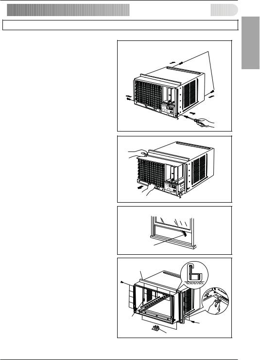
1.Remove the screws which fasten the cabinet at both sides and at the back.
2.Slide the unit out from the cabinet by gripping the base pan handle and pulling forward while bracing the cabinet.
3.Cut the window sash seal to the proper length. Peel off the backing and attach the Foam-PE to the underside of the window sash.
Shipping screws |
Fig. 1 |
ENGLISH
4. Insert the Frame guides into the bottom of the cabinet.
5. Insert the Frame Curtain into the Top retainer bar |
Fig. 2 |
and Frame guides. |
|
6. Fasten the curtains to the unit with 10 screws (Type A) at both sides.
Foam-PE |
Fig. 3 |
|
Top retainer bar |
|
|
Screw |
|
|
(Type A) |
Screw(Type A) |
|
Frame guide |
Fig. 4 |
|
Owner’s Manual |
13 |
|
Installation

 Cabinet Installation


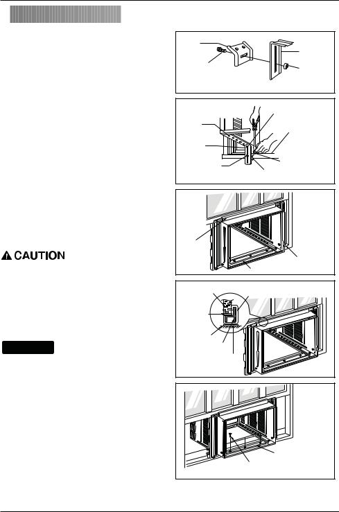
1.Open the window. Mark a line on the center of the window stool between the side window stop moldings.
Loosely attach the sill bracket to the support bracket using the carriage bolt and the lock nut.
2.Attach the sill bracket to the window sill using the screws (Type B).
Carefully place the cabinet on the window stool and align the center mark on the bottom front with the center line marked window stool.
3.Using the M-screw and the lock nut, attach the support bracket to the cabinet track hole. Use the first track hole after the sill bracket on the outer edge of the window sill. Tighten the carriage bolt and the lock nut. Be sure the cabinet slants outward.
Do not drill a hole in the bottom pan. The unit is designed to operate with approximately 1/2" of water in bottom pan.
4.Pull the bottom window sash down behind the Top retainer bar until they meet.
NOTICE
1.Do not pull the window sash down so tightly that the movement of Frame curtain is restricted. Attach the cabinet to the window stool by driving the screws (Type B) through the cabinet into window stool.
2.The cabinet should be installed with a very slight tilt downward toward the outside.
Sill |
|
|
Bracket |
|
Support |
Carriage |
|
Bracket |
|
Lock nut |
|
Bolt |
|
|
(M-Screw) |
|
Fig. 5 |
|
|
|
|
Machine screw(Type D) |
|
Cabinet |
and lock nut |
|
|
|
|
Track hole |
Outer edge |
|
|
of window |
|
Support |
sill |
|
Bracket |
|
|
Carriage bolt |
Screw(Type B) |
|
Sill bracket |
|
|
and lock nut |
Fig. 6 |
|
|
|
|
Top |
|
retainer |
|
bar |
Window stool |
|
|
Front angle |
Fig. 7 |
Window sash Top retainer bar |
|
Foam-PE |
Cabinet
Frame curtain
Foam-PE
Fig. 8
 Sash track
|
Front Angle |
Screw(Type B) |
Fig. 9 |
|
14 Room Air Conditioner
 Loading...