


User’s Manual
LG Programmable Logic Controller
FieldBus Link
Module MASTER-K K7F-FUEA
K4F-FUEA
K3F-FUEA
LG Industrial Systems

Contents
Chapter 1 |
Introduction.................................................................. |
1-1 |
Chapter 2 Terms and concepts of communication |
|
|
2.1 |
Description of terms ................................................................................... |
2-1 |
2.2 |
Concept of Fnet communication ................................................................ |
2-4 |
2.2.1 |
How to generate and move LAS ................................................................................... |
2-4 |
2.2.2 |
How to assign token ..................................................................................................... |
2-4 |
Chapter 3 |
General specifications |
|
3.1 |
General specifications of communication module(Fnet) ......................... |
3-1 |
3.2 |
Structure and configuration ........................................................................ |
3-2 |
3.2.1 |
Fnet master module structure : K7F-FUEA, K7F-FUOA, K4F-FUEA, K3F-FUEA ....... |
3-2 |
3.2.2 |
Fnet slave module structure : K7F-RBEA, K7F-RBOA, K4F-RBEA ............................. |
3-4 |
3.2.3 |
Fnet Computer interface module structure : G0L-FUEA ............................................... |
3-6 |
3.2.4 |
Fnet LED signal name and indication content .............................................................. |
3-7 |
3.2.5 |
Fnet station number setting .......................................................................................... |
3-7 |
3.2.6 |
Fnet mode setting ......................................................................................................... |
3-8 |
Chapter 4 |
Transmission specifications |
|
4.1 |
Transmission specifications of Fnet .......................................................... |
4-1 |
4.1.1 |
Transmission specifications of Fnet Master module...................................................... |
4-1 |
4.1.2 |
Transmission specifications of Fnet Slave module ....................................................... |
4-2 |
4.1.3 |
Transmission specifications of Fnet Option module ..................................................... |
4-2 |
4.2 |
Cable specifications .................................................................................... |
4-5 |
4.2.1 |
Twisted pair cable for Fnet ........................................................................................... |
4-5 |
4.2.2 |
Optical cable for Fnet .................................................................................................... |
4-6 |
4.3 |
How to connect communication cable ...................................................... |
4-8 |
4.3.1 |
Electric(twisted pair) cable connection .......................................................................... |
4-8 |
4.3.2 |
Electric(twisted pair) cable connector connection ........................................................ |
4-8 |
4.3.3 |
Optical cable connection ............................................................................................... |
4-9 |
4.4 |
Terminal resistance ..................................................................................... |
4-9 |
4.4.1 Electric network terminal resistance of Fnet ................................................................. |
4-9 |

Contents
Chapter 5 System configuration
5.1 |
MASTER-K PLC network system ................................................................ |
5-1 |
5.2 |
Fnet network system ................................................................................... |
5-2 |
5.2.1 Configuration of Fnet master system (electric network) ............................................... |
5-2 |
|
5.2.2 Configuration of Fnet master system (optical network) ................................................ |
5-2 |
|
5.2.3Configuration of Fnet master system (network combined with electric/optical module) 5-3
5.2.4 Configuration of Fnet slave system (electric network) .................................................. |
5-4 |
|
5.2.5 Configuration of Fnet slave system (optical network) ................................................... |
5-5 |
|
5.2.6 |
Configuration of Fnet slave system (electric/optical network) ...................................... |
5-6 |
5.2.7 |
Configuration of Fnet combined system (electric/optical network) ............................ |
5-7 |
Chapter 6 Communication program
6.1 |
Programming method .................................................................................. |
6-1 |
6.2 |
High speed link ............................................................................................... |
6-2 |
6.2.1 |
Introduction ................................................................................................................... |
6-2 |
6.2.2 |
Procedure of high speed link parameter setting............................................................ |
6-3 |
6.2.3 High speed link parameter setting ................................................................................. |
6-4 |
|
6.2.4 |
Operation procedure by .......................................................................... |
6-8 |
6.2.5 |
Information of ......................................................................................... |
6-9 |
6.2.6 |
Speed calculation of high speed link ........................................................................... |
6-14 |
6.2.7 Ex. 1 : among PLCs of Fnet ................................................................ |
6-17 |
|
6.2.8 Ex. 2 : of master + remote I/O stations in Fnet ................................... |
6-20 |
|
6.3 |
Communication instructions .................................................................... |
6-25 |
6.3.1 |
Introduction .................................................................................................................. |
6-25 |
6.3.2 |
Programming procedure.............................................................................................. |
6-25 |
6.3.3 Types of communication instructions ......................................................................... |
6-25 |
|
|
READ........................................................................................................................... |
6-26 |
|
WRITE ......................................................................................................................... |
6-27 |
|
STATUS....................................................................................................................... |
6-27 |
|
RGET........................................................................................................................... |
6-28 |
|
RPUT ........................................................................................................................... |
6-29 |
6.3.4 |
The input condition of communication instructions...................................................... |
6-29 |
6.3.5 Example of Read / Write instructions .......................................................................... |
6-30 |
|
6.4 |
KGLWIN remote connection service ........................................................ |
6-34 |
6.4.1 |
Introduction ................................................................................................................. |
6-34 |
6.4.2 |
KGLWIN remote connection ....................................................................................... |
6-35 |
6.4.3 |
Remote module information ....................................................................................... |
6-38 |

Contents
Chapter 7 |
Diagnosis function |
|
7.1 |
Self diagnosis function of Fnet communication module .......................... |
7-1 |
7.1.1 |
Self diagnosis function during running .......................................................................... |
7-1 |
7.1.2 |
Communication diagnosis by test mode ....................................................................... |
7-1 |
Chapter 8 |
Installation and testing operation |
|
8.1 |
Installation and testing operation of Fnet communication module ......... |
8-1 |
8.1.1 |
Installation of Fnet master module ................................................................................ |
8-1 |
8.1.2 |
Installation of Fnet slave module .................................................................................. |
8-2 |
8.1.3 |
Installation procedure of Fnet module .......................................................................... |
8-3 |
8.1.4 |
Cautions on installation of Fnet module ....................................................................... |
8-4 |
8.1.5 |
Preparations during testing operation of Fnet module .................................................. |
8-6 |
8.1.6 |
Testing operation procedure of Fnet module ................................................................ |
8-7 |
8.2 |
Installation and testing operation of Fnet option unit .............................. |
8-9 |
8.2.1 |
Active coupler of Fnet .................................................................................................... |
8-9 |
8.2.2 |
E/O converter(Electric/optical signal converter) ......................................................... |
8-10 |
8.2.3 |
Repeater(Electric signal restructure) .......................................................................... |
8-11 |
8.3 |
Repair and check ...................................................................................... |
8-16 |
8.3.1 |
Daily check .................................................................................................................. |
8-16 |
8.3.2 |
Regular check ............................................................................................................. |
8-17 |
Chapter 9 Troubleshooting |
|
|
9.1 |
Abnormal operations .................................................................................. |
9-1 |
9.2 |
Troubleshooting by each error code ......................................................... |
9-3 |
9.2.1 Error code E00-01 : Hardware error ............................................................................. |
9-3 |
|
|
Error code E00-03 : Hardware error of option module .................................................. |
9-3 |
9.2.2 |
Error code E00-02 : Interface error ............................................................................... |
9-4 |
9.2.3 Error code E00-04 : I/O initialization error of FSM(Fieldbus Slave Module) ................. |
9-5 |
|
9.2.4 |
Error code E01-01 : Communication failure in Fnet ..................................................... |
9-6 |
|
Error code E01-03 : Communication failure in FOU group ........................................... |
9-6 |
9.2.5 |
Error code E02-01 : PLC interface error during operation ............................................ |
9-7 |
9.2.6 Error code E02-02 : Slave mounting and writing interface error during operation ....... |
9-8 |
|
9.2.7 Error code E03-01 : parameter error ..................................................... |
9-9 |
|

Contents
9.2.8 |
Error code E03-02 |
: not run ................................................................ |
9-10 |
9.2.9 |
Error code E03-03 : RUN link contact of not ON ................................. |
9-11 |
|
9.2.10 |
Error code E03-04 |
: Trouble contact of ON ......................................... |
9-12 |
9.2.11 |
Error code E04-01 |
: Execution error of Fnet communication command .................... |
9-13 |
|
Error code E04-02 |
: Execution error of Mnet communication command .................... |
9-13 |
9.2.12 |
Error code E05-01 |
: Time out error in KGLWIN communication ................................. |
9-14 |
9.2.13 |
Error code E05-02 |
: Internal error in the Fnet/Mnet KGLWIN communication ........... |
9-15 |
Appendix
A1. |
LED specifications ...................................................................................... |
A-1 |
A1.1 |
LED specification of Fnet master module ..................................................................... |
A-1 |
A1.2 |
LED specification of slave module ................................................................................ |
A-4 |
A1.3 |
LED specification of stand-alone type remote module(G0L-SMQA/SMIA/SMHA) ...... |
A-7 |
A1.4 |
LED specification of repeater module(G0L-FREA) ...................................................... |
A-7 |
A1.5 |
LED specification of electric and optical signal switching module(G0L-FOEA) ........... |
A-7 |
A1.6 |
LED specification of active coupler module(Optical signal distributor) ......................... |
A-7 |
A1.7 |
LED specifications of Mnet communication module ..................................................... |
A-8 |
A2. |
Communication module setting in the Fnet/Mnet PC ............................. |
A-10 |
A3. |
STATUS code value and description for communication instructions.. |
A-11 |
A3.1 |
Errors received from communication module ............................................................. |
A-11 |
A3.2 |
STATUS values indicated in CPU .............................................................................. |
A-12 |
A4. |
Outward dimension .................................................................................. |
A-13 |
A4.1 |
For mounting GM1/2/3 ................................................................................................ |
A-13 |
A4.2 |
For mounting GM4 ...................................................................................................... |
A-15 |
A4.3 |
For mounting on GM6 ................................................................................................. |
A-16 |
A4.4 |
For mounting on PC(Computer) ................................................................................. |
A-17 |
A4.5 |
Fnet option module ..................................................................................................... |
A-18 |

1. Introduction
! " #
!$%
MASTER-K Fnet
& ' ( ) ! ' *'$
+ ) ," )
! ( & ! , ( ! ) ( ! ! "
)) - ) . ) )
-) . , ) ! ) & ! & ) ( &
! , " ) & ) ! !) ) ( ) * & (
& ) ( ! , "
Remark
1.MASTER-K Fnet is abbreviated as Fnet for simplicity of description.
2.Program in this User’s Manual has been prepared on the basis of KGLWIN V1.3.
1-1

1. Introduction
, ,$/"/ , " !
, "
Table 1.1 Type of MASTER-K PLC communication module
Network |
Module |
Type of |
Name of |
Mounting base |
||
connection cable |
communication module |
|||||
|
|
|
||||
|
|
|
|
G0L-FUEA |
Computer |
|
|
|
|
|
|
|
|
|
Master module |
Twisted pair |
|
K7F-FUEA |
K1000S |
|
|
(electric) |
Interface |
|
|
||
|
K4F-FUEA |
K300S |
||||
|
(FMM) |
|||||
|
|
|
|
|
||
|
|
|
K3F-FUEA |
K200S |
||
|
|
|
|
|||
|
|
|
|
|
|
|
|
|
Optical |
|
K7F-FUOA |
K1000S |
|
|
|
|
|
|
|
|
|
|
Twisted pair |
|
K7F-RBEA |
K1000S |
|
|
|
|
|
|
||
|
|
|
K4F-RBEA |
K300S |
||
|
|
(electric) |
|
|||
|
|
|
|
|
||
|
Slave module |
Remote I/O |
G0L-SMQA |
Single |
||
|
|
|||||
|
(FSM) |
|
|
|
|
|
MASTER-K |
|
|
G0L-SMIA |
Single |
||
|
Optical |
|
|
|
||
|
|
G0L-SMHA |
Single |
|||
Fnet |
|
|
||||
|
|
|
|
|
||
|
|
|
|
K7F-RBOA |
K1000S |
|
|
|
|
|
|
|
|
|
|
Twisted pair |
Repeater |
G0L-FREA |
Single |
|
|
|
|
|
|
|
|
|
|
Optical/Twisted pair |
Optical/electr |
G0L-FOEA |
Single |
|
|
|
ic converter |
||||
|
|
|
|
|
||
|
|
|
|
|
|
|
|
Option module |
|
Active |
G0L-FACA |
|
|
|
Optical |
G0L-FAPA |
Single |
|||
|
|
coupler |
||||
|
|
|
G0L-FABA |
|
||
|
|
|
|
|
||
|
|
|
|
|
|
|
|
|
Cable |
Cable |
G0C-T |
Twisted pair cable |
|
|
|
|
|
|||
|
|
G0C-F |
Optical fiber cable |
|||
|
|
|
|
|||
|
|
|
|
|
|
|
1-2

2. Terms and Concepts of communication
2.1Description of terms
Master module(Fnet Master Module ; FMM) $!! ! ! '*0 ) ! "
Slave module(Fnet Slave Module; FSM) $!! ! ! ! ) ! "
Option module(Fnet Option Module)
$ !! ! , & ( 1 !! (
, !) , "
Local station
2 3'# ( ! ( , ) , !
! , "
Remote station
)) ) ( !!
Remote I/O station
' ) * ) ! !! ! !
'*0 ! ! ! & , '*0 ! ! "
Fnet
$, & ! & ( )
) ! & 0 '" )
45-/ ) ( .( 4/-6/"56 ) ( .( ) ( ( "( )
( )) ) )) (
"
2-1

2.Terms and Concepts of communication
Token
, ! , , , , ) ! !"
SAP(Service Access Point)
! & !! ( )) )) , " & (
7 8 ( "-9 : 8 (
.
Fnet station number
! !! !-;$ $(""" ". ) ,$) "
! $ !! ! (
! & , & ! !
"
Active coupler
! , ) ! ) , ( )
( , !) ) !! ,
"
Repeater
1 !! ( 1
!! , !) !! , "
E.O.C(Electric/Optical Converter)
! & ) !! , !! , (
!! , ) !! , ( ,
!) , "
2-2

2. Terms and Concepts of communication
Manchester Biphase-L
8 ! ! $" 8 ! , (
& & "
CRC(Cyclic Redundancy Check)
! ( ! ! <
+ , ! ( ! "
Terminal resistance
= ! !) ! , ) & , ) ) (
!$//> ( /*53 ! ;? ( /*@3"
High speed link
! , !! ! ( ! &
, ) ( 1 !! , ) ! 2 3'#"
KGLWIN(Programming and debugging tool)
) , ! !( ( ( )( ,
! "
FAM(FA Manager)
) , )) & ! (
& ) ( 1 ( ,* , & (
* ) ) , ! ! ,$! !) "
Segment
, ! ( , ,
&-2 ( 0 ( ) ."
Network
!! !( , ,! ! ( ! "
2-3
2.Terms and Concepts of communication
2.2Concept of Fnet communication
!$!! ! -& ." 0
$!! ! ($!! ! "
2.2.1 How to generate and move LAS
! , !! ! ( , , %
/.! , ($!! ! )
"
5.3 ) ! ! ! ! , (
!! ! ! "
6.' ) ! , ! !! ( !! !
! ! ,$( "
@. 0 1 , "
2.2.2How to assign token(Suppose that the Station FMM_01 is LAS)
FMM_01(LAS) |
FMM_02 |
|
FMM_03 |
|
FMM_04 |
FMM_05 |
|||||||||||||
|
|
|
|
|
|
|
|
|
|
|
|
|
|
|
|
|
|
|
|
|
|
|
|
|
|
|
|
|
|
|
|
|
|
|
|
|
|
|
|
Data transmission of LAS’s own station
Use within 8ms
Data transmission of self station Use within 8ms
station of 02_FMM
Token transmission of  FMM_01 (LAS station also transmits its own FMM 01)
Return of token
Token transmission |
Return of token |
Circulated
Token
Passing
token of Return |
Token transmission of station FSM 05 |
Data transmission of self station
Use within 8ms
|
Token |
|
||||
|
transmission of |
|
||||
|
station FSM_03 |
Data transmission of |
||||
|
|
|
|
|
|
self station |
|
|
|
|
|
|
|
|
|
|
|
|
|
Use within 8ms |
|
|
Return of |
||||
|
|
|
||||
|
|
token |
|
|||
|
Token |
|
||||
|
transmission of |
|
||||
|
station FSM_04 |
Data transmission of |
||||
|
|
|
|
|
|
self station |
|
|
|
|
|
|
|
|
|
Return of |
Use within 8ms |
|||
|
|
|
||||
|
|
token |
|
|||
AToken return in each station is performed to present LAS station.
2-4

3. General specifications
3.1General specifications of communication module(Fnet)
2 ) %
6"/ 2 )
No. |
Item |
|
|
|
|
Spec. |
|
Related spec. |
||||
1 |
Operating temp. |
0 +55 |
|
|
|
|
|
|
|
|
||
|
|
|
|
|
|
|
|
|
|
|
|
|
2 |
Storage temp. |
-25 +70 |
|
|
|
|
|
|
|
|
||
|
|
|
|
|
|
|
|
|
|
|
|
|
3 |
Operating moist. |
5~95% RH, non-condensing |
|
|
|
|
|
|||||
|
|
|
|
|
|
|
|
|
|
|
|
|
4 |
Storage moist. |
5~95% RH, non-condensing |
|
|
|
|
|
|||||
|
|
|
|
|
|
|
|
|
|
|
|
|
|
|
|
|
|
For discontinuous vibration |
|
|
|||||
|
|
|
|
|
|
|
|
|
|
|
|
|
|
|
|
Frequency |
|
Acceleration |
|
Amplitude |
Number |
|
|||
|
|
|
|
|
|
|
|
|
|
|
|
|
|
|
10 f 57Hz |
|
- |
|
|
0.075mm |
|
|
|||
|
|
|
|
|
|
|
|
|
|
|
|
|
5 |
Vibration |
57 f 150Hz |
|
9.8 |
|
- |
|
|
ICE 1131-2 |
|||
|
|
|
|
|
|
|
|
|
|
|||
|
For continuous vibration |
|
|
|
Each 10 times in |
|||||||
|
|
|
|
|
|
|
||||||
|
|
|
Frequency |
|
Acceleration |
|
Amplitude |
X,Y,Z directions |
|
|||
|
|
|
|
|
|
|
|
|
|
|
|
|
|
|
10 f 57Hz |
|
- |
|
|
0.035mm |
|
|
|||
|
|
|
|
|
|
|
|
|
|
|
|
|
|
|
57 f 150Hz |
|
4.9 |
|
- |
|
|
|
|||
|
|
|
|
|
|
|
|
|
|
|
|
|
|
|
• |
Max. impact acceleration:147 (15G) |
|
|
|||||||
6 |
Impact |
• |
Authorized time : 11ms |
|
|
|
|
|
|
IEC 1131-2 |
||
• |
Pulse wave |
: Sign half-wave |
|
pulse(each |
3 times in X,Y,Z |
|||||||
|
|
directions) |
|
|
|
|
|
|
|
|
||
|
|
|
|
|
|
|
|
|
|
|
|
|
|
|
Square wave |
|
|
|
|
|
|
|
Test spec. reference |
||
|
|
1,500V |
|
|
|
|
|
|
within LG Industrial |
|||
|
|
Impulse noise |
|
|
|
|
|
|
||||
|
|
|
|
|
|
|
|
|
|
|
|
Systems |
|
|
Static electric |
Voltage : 4kV(Contact discharging) |
IEC 1131-2, |
||||||||
|
|
discharging |
IEC 801-2 |
|||||||||
|
|
|
|
|
|
|
|
|
||||
|
|
|
|
|
|
|
|
|
|
|
||
|
|
Radiation |
|
|
|
|
|
|
|
IEC 1131-2, |
||
|
|
electric field |
27 500 MHz, 10V/m |
|
||||||||
|
|
|
IEC 801-3 |
|||||||||
7 |
Noise |
noise |
|
|
|
|
|
|
|
|||
|
|
|
|
|
|
|
|
|||||
|
|
|
|
|
|
|
|
|
|
|
|
|
|
|
|
|
|
|
|
|
|
Digital |
|
Digital input/output |
|
|
|
|
|
|
|
|
|
|
|
(less than |
|
|
|
|
|
|
|
|
|
|
|
input/ |
|
|
|
|
|
Fast |
|
Power |
|
|
24V)Analog |
|
||||
|
|
Segment |
|
output |
|
IEC 1131-2, |
||||||
|
|
transient/burst |
module |
|
|
input/output |
||||||
|
|
noise |
|
|
|
|
(24V or |
|
communication |
IEC 801-4 |
||
|
|
|
|
|
|
more) |
|
|||||
|
|
|
|
|
|
|
|
|||||
|
|
|
|
|
|
|
|
|
|
interface |
|
|
|
|
|
|
|
|
|
|
|
|
|
|
|
|
|
|
|
|
|
|
|
|
|
|
|
|
|
|
|
|
|
Voltage |
2kV |
|
1kV |
|
0.25 kV |
|
|
|
|
|
|
|
|
|
|
|
|
|
||
8 |
Ambient conditions |
No corrosive gas and dust |
|
|
|
|
|
|
|
|||
|
|
|
|
|
|
|
|
|
|
|
||
9 |
Height |
Up to 2,000m |
|
|
|
|
|
|
|
|
||
|
|
|
|
|
|
|
|
|
|
|
||
10 |
Pollution level |
2 or less |
|
|
|
|
|
|
|
|
||
|
|
|
|
|
|
|
|
|
|
|||
11 |
Cooling type |
Natural air cooling |
|
|
|
|
|
|
|
|||
|
|
|
|
|
|
|
|
|
|
|
|
|
Remark
1.IEC(International Electro-technical Commission) : International non-governmental association, which establishes international standards in the field of electric and electronics.
2.Pollution level : This is an indication showing pollution of surrounding environment, which determines insulation performance of device, and generally the pollution level 2 means the conditions in which only non-conductive pollution occurs.
But, temporary conduction may occur according to condensing.
3-1
3.General specifications
3.2Structure and configuration
, ) & )$! "
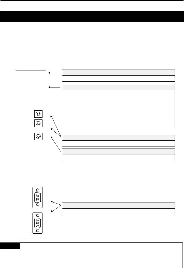
3.2.1 Fnet master module structure : K7F-FUEA, K7F-FUOA, K4F-FUEA, K3F-FUEA
1) K7F-FUEA, K7F-FUOA, K4F-FUEA
Type name indicating section
Indicates type name of communication module
LED indicating section
RUN |
Indicates the status of CPU module and interface |
|
|
LAS |
Indicates that communication module is performing LAS function. |
|
|
TOKEN |
Indicates whether communication module has a token or not. |
|
|
Tx/Rx |
Indicates whether communication module is transmitting/ receiving |
|
or not. |
|
|
FAULT |
Flickers when the error that normal operation is not possible |
|
occurred in communication module |
|
|
Station number setting switch
Sets station number in the range of 0~63 station(Use decimal).
Mode setting switch
Sets operation mode of communication module
Communication connector
Connector for electric cable connection to connect communication module.
Remark
1.In the figure shown above, connector of K7F-FUOA is made of optical connector.
2.For mode setting switch, see 3.2.6 Fnet mode setting.
3-2

3. General specifications
2) K3F-FUEA
LED indicating section
RUN |
Indicates the status of CPU module and interface |
|
|
LAS |
Indicates that communication module is performing LAS function. |
|
|
TOKEN |
Indicates whether communication module has a token or not. |
|
|
Tx/Rx |
Indicates whether communication module is transmitting/ receiving |
|
or not. |
|
|
FAULT |
Flickers when the error that normal operation is not possible |
|
occurred in communication module |
|
|
Type name indicating section
Indicates type name of communication module
Mode setting switch
Sets operation mode of communication module
Communication connector
Connector for electric cable connection to connect communication module.
Remark
1.The station number setting switch is placed in the case.
3-3

3. General specifications
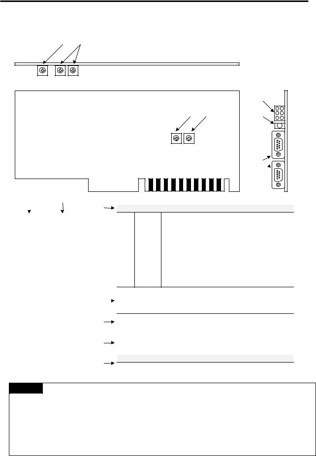
3.2.2Fnet slave module structure : K7F-RBEA, K7F-RBOA, K4F-RBEA
K7F-RBEA |
|
|
|
|
|
|
|
|
|
|
|
|
|
|
Remark |
Type name indicating section
Indicates type name of communication module
LED indicating section |
|
|
|
RUN |
Indicates the status of communication module |
"# |
$% |
&'()#TOKEN*+ ,Indicates whether-communication./ module has a token
&01 0 |
or not. |
2 ./ |
|
34"5&Tx/RxDE ?@ FGIndicates whether communication module is |
|
Y |
transmitting/receiving or not. |
67 89 :;< => ?@ AB C1' DE |
|
34"5&FAULT?@ FGFlickers when the communication error occurred.
SYS |
Flickers when serious error of system itself or I/O module |
|
|
FAULT |
error occurred |
!
Station number setting switch
Sets station number in the range of 0~63 station(Set in decimal).
HI J
Mode setting switch
Sets operation mode of communication module
Communication connector (RS-232C)
Cable connector of KGLWIN connection.
Z[\C# STU Q R VWX
Communication connector
Connector for electric cable connection to connect communication
K LMNO < POQ R STU VWX
module.
In the figure shown above, connector of K7F-RBOA is made of optical connector, and there is no RS-232C port in K4F-RBEA.
3-4

3. General specifications
|
8 |
8 |
Station number setting switch
Sets master station number of remote
communication module(Set in the range of 0~63 station using decimal).
Output of emergency data
! " #$%
Specifies output data type when
&' ( ) *+,- communication failure by cable cut off.
./. 0123 4 5 67
(See 3.2.6 Fnet mode setting)
3-5
3. General specifications
3.2.3Fnet Computer interface module structure : G0L-FUEA
B/ B/>
|
|
|
|
+opq rrpstt

|
|
|
|
|
|
|
|
|
|
|
|
|
|
|
|
|
|
|
|
|
|
|
|
|
|
|
|
LED indicating section |
|
||||||
|
|
|
|
|
|
|
|
|
|
|
|
|
||
|
|
Port |
|
Address |
|
|
|
No.1 |
|
POWER |
|
Indicates whether power is being supplied to |
|
|
|
selection |
|
selection |
|
|
|
|
|
|
|
communication module |
|
||
|
|
|
|
|
|
|
|
j |
+Bk ( 9: ,-L ^l mn GH 56 |
|
||||
|
|
|
|
|
|
|
|
|
No.2 |
|
RUN |
Indicates the status of CPU module and interface |
|
|
0 |
|
3E0 |
|
FC00 |
|
|
|
|
|
|||||
|
|
|
|
j |
|
()* +) ,-. /01 2 34 56 |
|
|||||||
|
|
|
|
|
|
|
|
No.3 |
|
LAS |
Indicates that communication module is performing |
|
||
1 |
|
3C0 |
|
F800 |
|
|
|
|
|
|||||
|
|
|
|
|
|
|
|
|
j |
|
7 8 9: ,-7 8 ;< %=>?@ 56" |
|
||
2 |
|
3A0 |
|
F400 |
|
|
|
|
|
|
|
LAS function. |
|
|
|
|
|
|
No.4 |
|
TOKEN |
Indicates whether communication module has token |
|
||||||
|
|
|
|
|
|
|
|
|
|
|
||||
3 |
|
380 |
|
F000 |
|
|
|
|
|
|||||
|
|
|
|
j |
ABC * 9: ,-DE F GH 56 |
|
||||||||
|
|
|
|
|
|
|
|
|
|
|
|
|
or not. |
|
4 |
|
360 |
|
EC00 |
|
|
|
|
|
|
|
|
||
|
|
|
|
j |
AIJ(I 9: ,-K%: GH 56 |
|
||||||||
|
|
|
|
|
|
|
|
|
No.5 |
|
Tx/Rx |
Indicates whether communication module is |
|
|
5 |
|
340 |
|
E800 |
|
|
|
|
|
|||||
|
|
|
|
j |
|
|
|
transmitting/receiving or not. |
|
|||||
6 |
|
320 |
|
E400 |
|
|
|
)7A 9: ,-L !3MN& ;OP% QR LS TU6 VW |
|
|||||
|
|
|
|
No.6 |
|
FAULT |
Flickers when the error that normal operation is not |
|
||||||
|
|
|
|
|
|
|
|
|
|
|||||
7 |
|
300 |
|
E000 |
|
|
|
possible occurred in communication module |
|
|||||
|
|
|
|
|
|
|
|
|
||||||
8 |
|
2E0 |
|
DC00 |
|
|
|
|
||||||
|
|
|
|
|
|
|
|
|
|
|||||
|
|
|
|
|
|
|
|
|
|
|
|
|
|
|
9 |
|
2C0 |
|
D800 |
|
|
|
Station number setting switch!"#$%& !' |
|
|||||
|
|
|
|
|
|
|
|
|
|
|
|
|
|
|
|
|
|
|
|
|
|
|
Sets station number in the range of 0~63 station(Set in decimal). |
|
|||||
A |
|
2A0 |
|
D400 |
|
|
|
|
||||||
|
|
|
|
|
|
|
|
|
|
|
|
|
|
|
|
|
|
|
|
|
|
|
|
|
|||||
B |
|
280 |
|
D000 |
|
|
|
|
|
|
||||
|
|
|
|
|
|
|
|
Mode setting switch |
|
|||||
C |
|
260 |
|
CC00 |
|
|
|
|
||||||
|
|
|
|
|
|
9: ,-OX ,Y ! |
|
|||||||
D |
|
240 |
|
C800 |
|
|
|
Sets operation mode of communication module |
|
|||||
|
|
|
|
|
|
|
|
|
|
|
|
|
|
|
|
|
|
|
|
|
|
|
|
|
|||||
E |
|
220 |
|
C400 |
|
|
|
|
|
|
|
|
|
|
|
|
|
|
|
|
|
|
Reset switch |
|
|
||||
F |
|
200 |
|
C000 |
|
|
|
|||||||
|
|
|
|
|
|
|
||||||||
|
|
|
|
|
A switch to initialize communication module |
|
||||||||
|
|
|
|
|
|
|
|
|
9: ,-@ f;g 6h ; ] 2 i |
|
||||
|
|
|
|
|
|
|
|
|
|
|
||||
|
|
|
|
|
|
|
|
|
Communication connector |
|
||||
|
|
|
|
|
|
|
|
|
|
|||||
|
|
|
|
|
|
|
|
|
Connector for electric cable connection to connect communication |
|
||||
|
|
|
|
|
|
|
|
|
9: ,module.-@ Z[\; ] ^;_` abc de0 |
|
||||
|
|
|
|
|
|
|
|
|
|
|
|
|
|
|
Remark
1.For mode setting switch, see 3.2.6 Fnet mode setting.
2.Port is set to No.5(340) and address is set to No.9(D800) by factory default.
3.This should be set in order not to be duplicated with other device area of computer previously used, and add DEVICE=C:\WINDOWS\EMM386.EXE NOEMS X=D800-D8FF(if address has been set to No.9(D800)) in CONFIG.SYS to use set area for not continuous or extended area of computer but this module.
3-6

3. General specifications
3.2.4 Fnet LED signal name and indication content
Device |
LED |
Meaning of LED indication |
LED On |
LED Off |
|
type |
Name |
||||
|
|
|
|||
|
RUN |
Indicates the status of CPU module and interface |
Normal |
Abnormal |
|
|
|
|
|
|
|
K7F-FUEA |
LAS |
Indicates that communication module is performing LAS |
In proceeding |
|
|
K7F-FUOA |
|
function. |
|
|
|
TOKEN |
Indicates whether communication module has token or not. |
Has |
Does not |
||
K4F-FUEA |
|||||
have |
|||||
K3F-FUEA |
|
|
|
||
|
|
|
|
||
Tx/Rx |
Indicates whether communication module is transmitting/ |
Flicker during |
|||
GOL-FUEA |
|||||
receiving or not. |
communication |
||||
|
|
||||
|
|
|
|
|
|
|
FAULT |
Indicates the status of communication module. |
Abnormal |
Normal |
|
|
|
|
|
|
|
|
RUN |
Indicates the status of communication module. |
Normal |
Abnormal |
|
|
|
|
|
|
|
|
TOKEN |
Indicates whether communication module has token or not. |
Has |
Does not |
|
|
have |
||||
K7F-RBEA |
|
|
|
||
|
|
|
|
||
|
Indicates whether communication module is transmitting/ |
Flicker during |
|||
K7F-RBOA |
Tx/Rx |
||||
receiving or not. |
communication |
||||
K4F-RBEA |
|
||||
|
|
|
|
||
FAULT |
Indicates whether communication error exists or not. |
Abnormal |
Normal |
||
|
|||||
|
|
|
|
|
|
|
SYS |
Indicates whether system error or I/O module error occurred |
Abnormal |
Normal |
|
|
FAULT |
or not. |
|||
|
|
|
|||
|
|
|
|
|
|
G0L-SMQA |
PWR |
Indicates power status. |
Power On |
Power Off |
|
|
|
|
|
||
|
|
Flicker during |
|||
G0L-SMIA |
TRX |
Indicates Tx/Rx or not of communication module. |
|||
communication |
|||||
G0L-SMHA |
|
|
|||
|
|
|
|
||
ERR |
Indicates communication error or not. |
Abnormal |
Normal |
||
|
|||||
|
|
|
|
|
|
* For details on LED, see Appendix A1, LED indication.
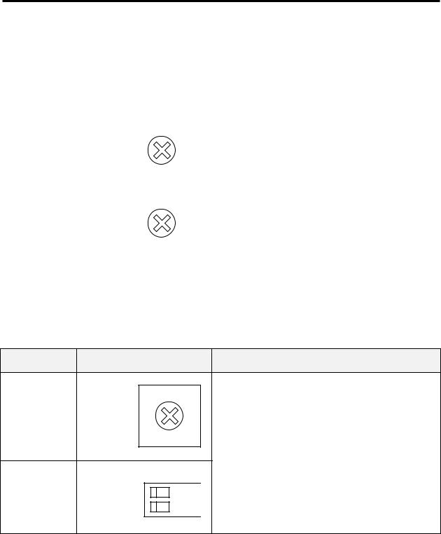
3.2.5 Fnet station number setting
|
!" # |
|
|
|
|
|
|
|
||
|
|
|
|
|
|
|
|
|
|
|
Applied |
|
Detailed drawing of |
|
|
|
Description |
||||
Device type |
|
station number switch |
|
|
|
|||||
|
|
|
|
|
|
|||||
K7F-FUEA |
|
|
|
|
|
(1) Station number can be set from 0 to 63(Decimal). |
||||
|
|
|
|
|
||||||
|
|
|
|
|
|
|
|
|
|
|
K7F-FUOA |
|
|
|
|
|
(2) |
Station number setting |
|||
K7F-RBEA |
|
|
|
|
|
|
|
(Factory default is 0) |
||
K7F-RBOA |
|
|
|
|
|
|
|
|
|
|
|
|
|
|
|
|
Switch |
Setting |
|
||
K4F-FUEA |
|
|
|
|
|
|
|
|
|
|
|
|
|
|
|
|
X 10 |
Sets ten’s figure of station number |
|
||
|
|
|
|
|
|
|
|
|
||
K4F-RBEA |
|
|
|
|
|
|
|
|
|
|
|
|
|
|
|
|
|
X 1 |
Sets one’s figure of station number |
|
|
K3F-FUEA |
|
|
|
|
|
|
|
|
|
|
G0L-FUEA |
|
|
|
|
|
(3) GM6 : The station setting switch is placed in the case. |
||||
G0L-SMQA |
|
|
|
|
|
|
|
|
|
|
G0L-SMIA |
|
|
|
|
|
|
|
|
|
|
G0L-SMHA |
|
|
|
|
|
|
|
|
|
|
|
|
|
|
|
|
|
|
|
|
|
|
|
|
|
|
|
|
|
|
|
|
3-7
3. General specifications
$ !" #
!$! ! ( ! & $&
!-! ."
Applied |
Detailed drawing of |
|
|
Description |
||||
Device type |
station number switch |
|
|
|||||
|
|
|
|
|||||
|
|
|
|
|
(1) Station number can be set from 0 to 63(Decimal). |
|||
|
|
|
|
|
||||
|
|
|
|
(2) Station number setting |
||||
|
|
|
|
|
||||
|
|
|
|
|
|
(Factory default is 0) |
||
K7F-RBEA |
|
|
|
|
|
|||
|
|
|
|
|
|
|
|
|
K7F-RBOA |
|
|
|
|
|
|
|
|
|
|
|
|
|
Switch |
Setting |
|
|
|
|
|
|
|
|
|
|
|
K4F-RBEA |
|
|
|
|
|
X 10 |
Sets ten’s figure of station number |
|
|
|
|
|
|||||
G0L-SMQA |
|
|
|
|
|
|
|
|
|
|
|
|
|
X 1 |
Sets one’s figure of station number |
|
|
|
|
|
|
|
|
|||
|
|
|
|
|
|
|||
G0L-SMIA |
|
|
|
|
|
|
|
|
|
|
|
|
|
|
|
|
|
G0L-SMHA |
|
|
|
|
|
|
|
|
|
|
|
|
|
|
|||
|
|
|
|
|
|
|
|
|
|
|
|
|
|
|
|
|
|
|
|
|
|
|
|
|
|
|
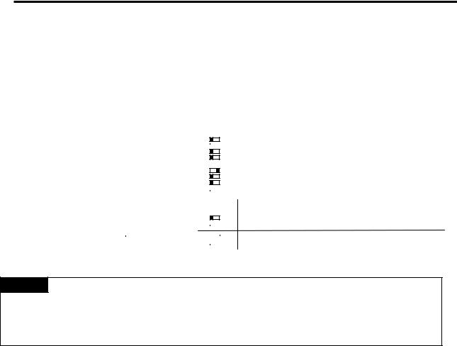
3.2.6 Fnet mode setting
% !
Applied Device type
K7F-FUEA
K7F-FUOA
K7F-RBEA
K7F-RBOA
G0L-FUEA
K4F-FUEA
K4F-RBEA
Detailed drawing of mode switch
|
|
|
|
|
|
|
|
|
|
|
|
|
|
|
2 |
|
|
|
1 |
|
! |
|
Description
(1)Mode can be set from 0 to 2. (GM6 : 0 ~ 3)
(2) Mode setting
(Factory default is 0)
|
|
Mode |
Function |
|
|
|
|
|
|
0 |
Performs normal operation |
|
|
|
|
|
|
1 |
Sets the unit as data transmitting station in |
|
|
|
communication test |
|
|
2 |
Sets the unit as data transmitting station in |
ON |
|
|
communication test |
|
|
|
|
|
|
|
|
|
|
|
|
* For details, see chapter 7, Diagnosis function.
3-8
3. General specifications
! # & #
'$& ! ( !! ! !
, !! ( , ) ) , '*0 &
! ) , ) "
Applied |
Detailed drawing |
|
|
|
|
|
|
|
|
|
|
|
|
Description |
||||||||||||
Device type |
of mode switch |
|
|
|
|
|
|
|
|
|
|
|
|
|||||||||||||
|
|
|
|
|
|
|
|
|
|
|
|
|
|
|
|
|
|
|
||||||||
|
|
|
|
|
|
|
|
|
|
|
|
|
|
|
|
|
|
|
|
|
|
|
|
|
|
|
|
|
|
|
|
|
|
|
|
|
|
Mode |
|
|
|
|
! "Function |
|
|
|
|
||||||
|
|
|
|
|
|
|
|
|||||||||||||||||||
K7F-RBEA |
|
|
|
|
|
|
|
|
|
|
|
|
|
|
Latches the last data during communication error. |
|
|
|
|
|
||||||
|
|
|
|
|
|
|
|
|
|
|
|
|
|
|
|
|
|
|
|
|
|
|||||
|
|
|
|
|
|
|
|
|
|
|
|
|
|
|
|
|
|
|
|
|
|
|||||
|
|
|
|
|
|
|
|
|
|
|
|
|
|
|
|
|
|
|
|
|
|
|
|
|
||
|
|
|
|
|
|
|
|
|
|
|
|
|
|
|
|
|
|
|
|
|
|
|
|
|
||
|
|
|
|
|
|
|
|
|
|
|
|
|
|
|
|
|
|
|
|
|
|
|
|
|
|
|
|
|
|
|
|
|
|
|
|
|
|
|
|
|
|
|
|
|
|
|
|
|
|
|
|
||
K7F-RBOA |
|
|
|
|
|
|
|
|
|
|
|
|
|
|
|
|
|
|
|
|
|
|
|
|
|
|
|
|
|
|
|
|
|
|
|
|
|
|
|
|
|
|
|
|
|
|
|
|
|
|
|
||
|
|
|
|
|
|
|
|
|
|
|
|
|
|
|
|
|
|
|
|
|
|
|
|
|
||
|
|
|
|
|
|
|
|
|
|
|
|
|
|
|
|
#$%& '() *+ ,-. |
|
|
||||||||
|
|
|
|
|
|
|
|
|
|
|
|
|
|
|
|
Outputs user-defined data during communication |
|
|
||||||||
|
|
|
|
|
|
|
|
|
|
|
|
|
|
|
error (Default is data reset). |
|
|
|||||||||
|
|
|
|
|
|
|
|
|
|
|
|
|
|
|
|
|
|
|
|
|||||||
|
|
|
|
|
|
|
|
|
|
|
|
|
|
|
|
|
|
|
|
|||||||
|
|
|
|
|
|
|
|
|
|
|
|
|
|
|
|
|
|
|
|
|
|
|
|
|
|
|
|
|
|
|
|
|
|
|
|
|
|
|
|
|
|
|
|
|
|
|
|
|
|
|
|
|
|
|
|
|
|
|
|
|
|
|
|
|
|
|
|
|
|
|
|
|
|
|
|
|
|
|
|
|
|
|
|
|
|
|
|
|
|
|
|
|
|
|
|
|
|
|
|
|
|
|
|
|
|
||
|
|
|
|
|
|
|
|
|
|
|
|
|
|
|
|
|
|
|
|
|
|
|
|
|
|
|
K4F-RBEA |
|
|
|
|
|
|
|
|
|
|
Mode |
|
|
|
|
! "Function |
|
|
||||||||
G0L-SMQA |
|
|
|
|
|
|
|
|
|
|
|
|
|
|
|
Latches the last data during communication error. |
|
|
|
|
|
|
||||
|
|
|
|
|
|
|
|
|
|
|
|
|
|
|
|
|
|
|
|
|
|
|
|
|
||
G0L-SMIA |
|
|
|
|
|
|
|
|
|
|
|
|
|
|
|
|
|
|
|
|
|
|
|
|
||
|
|
|
|
|
|
|
|
|
|
|
|
|
|
|
|
|
|
|||||||||
|
|
|
|
|
|
|
|
|
|
|
|
|
|
|
||||||||||||
|
|
|
|
|
|
|
|
|
|
|
|
|
|
#$%& '() *+ ,-. |
|
|
||||||||||
|
|
|
|
|
|
|
|
|
|
|
|
|
|
|
|
|||||||||||
G0L-SMHA |
|
|
|
|
|
|
|
|
|
|
|
|
|
|
|
|
|
Outputs user-defined data during communication |
|
|
||||||
|
|
|
|
|
|
|
|
|
|
|
|
|
|
|
error (Default is data reset). |
|
|
|||||||||
|
|
|
|
|
|
|
|
|
|
|
|
|
|
|
|
|
|
|
|
|
|
|
|
|
|
|
|
|
|
|
|
|
|
|
|
|
|
|
|
|
|
|
|
|
|
|
|
|
|
|
|
|
|
|
|
|
|
|
|
|
|
|
|
|
|
|
|
|
|
|
|
|
|
|
|
|
|
|
|
|
|
|
|
|
|
|
|
|
|
|
|
|
|
|
|
|
|
|
|
|
|
|
|
|
|
|
|
Remark
1.All of the switches are set to off by factory default.
2.User can input user-defined data for communication error in KGLWIN. (Refer to 6.6.7, Setting emergency output data of remote module.)
3-9

4. Transmission specifications
4.1Transmission specifications of Fnet
4.1.1Transmission specifications of Fnet master module
$! ! % ;$ $( ;$ $0 ( @$ $( 6$ $( 2>$
Table 4.1.1 Transmission specifications of Fnet master module
|
|
Item |
Specification |
|
|
Transmission speed |
1Mbps |
||
|
common in Fnet module |
|||
|
|
|
||
|
|
|
|
|
|
|
Encoding type |
Manchester Biphase-L |
|
|
|
|
|
|
|
|
Transmission distance |
Max. 750m |
|
|
|
(per segment) |
||
|
|
|
||
|
|
|
|
|
Electric |
|
Transmission distance |
Max. 750m × (6 repeater + 1) = 5.25 km |
|
|
|
(during using repeater) |
||
|
|
|
||
|
|
|
|
|
|
|
Transmission line |
Twisted pair shielded cable |
|
|
|
|
|
|
|
|
Transmission distance |
Max. 3km |
|
|
|
(per segment) |
||
|
|
|
||
Optical |
|
|
|
|
|
Transmission distance |
Max. 3km × (6 EOC +1) = 21km |
||
|
|
(during using EOC) |
||
|
|
|
||
|
|
|
|
|
|
|
Transmission line |
Optical cable |
|
|
|
|
|
|
Max. number of station connection |
Master + slave = 64 station |
|||
(At least one master should be connected) |
||||
|
|
|
||
|
|
|
||
|
Max. size of protocol |
256 byte |
||
|
|
|
|
|
|
|
Access type of |
Circulated token passing |
|
|
communication right |
|||
|
|
|||
|
|
|
|
|
|
Communication type |
Connection oriented service |
||
|
Connectionless service |
|||
|
|
|
||
|
|
|
||
|
Frame error check |
CRC 16 = X15 + X14 + X13 + ... + X2 + X + 1 |
||
4-1

4. Transmission specifications
4.1.2 Transmission specifications of Fnet slave module
$& ! %' ( ' ) ' *+$, ' *+$-' *+$.
Table 4.1.2 Transmission specifications of Fnet slave module
|
|
Item |
Specification |
|
Transmission speed |
1Mbps |
|
|
|
|
|
|
|
Encoding type |
Manchester Biphase-L |
|
|
|
|
|
|
Transmission distance |
Max. 750m |
|
|
(per segment) |
|
|
|
|
|
|
|
|
|
Electric |
|
Transmission distance |
Max. 750m × (6 repeater + 1) = 5.25km |
|
|
(during using repeater) |
|
|
|
|
|
|
|
|
|
|
|
Transmission line |
Twisted pair shielded cable |
|
|
|
|
|
|
Transmission distance |
Max. 3km × (6 EOC +1) = 21km |
Optical |
|
(during segment) |
|
|
|
||
|
|
|
|
|
|
Transmission line |
Optical cable |
|
|
|
|
Max. number of stations connected |
Link master class + Remote slave class = 64 |
||
|
|
|
|
|
Max. size of protocol |
256 byte |
|
|
|
|
|
|
|
Access type of |
Circulated token passing |
|
communication right |
||
|
|
||
|
|
|
|
|
Communication type |
Connection oriented service |
|
|
Connectionless service |
||
|
|
|
|
|
|
|
|
4.1.3 Transmission specifications of Fnet option module
$) ! %*+ ' *+ ( ' *+ /
*+
Table 4.1.3(A) Transmission specifications of repeater
Item |
Specification |
|
Communication speed |
1Mbps |
|
|
|
|
Encoding type |
Manchester Biphase-L |
|
|
|
|
Transmission line(Cable) |
Twisted pair shielded cable |
|
|
|
|
Max. extension distance per module |
750m |
|
|
|
|
Max. number of repeater between |
6 units |
|
stations |
||
|
||
|
|
|
Max. distance between stations |
5.25km(when 6 repeater is installed) |
|
|
|
|
Frame error check |
CRC 16 = X15 + X14 + X13 + ... + X2 + X + 1 |
4-2

4. Transmission specifications
0( 1 *+ (
Table 4.1.3(B) Transmission specifications of electric/optical converter
Item |
Specification |
Communication speed |
1Mbps |
|
|
Encoding type |
Manchester Biphase-L |
|
|
Transmission line(Cable) |
Optical cable, twist pair cable |
|
|
Max. transmission distance |
3km(Optical)/750m(electric) |
|
|
Function of signal regeneration |
Regenerating, Reshaping function |
|
|
Frame error check |
CRC 16 = X15 + X14 + X13 + ... + X2 + X + 1 |
2 1 3 |
4 *+ / |
|
Table 4.1.3(C) Transmission specification of active coupler |
||
|
|
|
Item |
|
Specification |
Communication speed |
|
1Mbps |
|
|
|
Encoding type |
|
Manchester Biphase-L |
|
|
|
Transmission line(Cable) |
|
Optical cable |
|
|
|
Max. transmission distance |
|
3km |
|
|
|
Function of signal regeneration |
|
Regenerating, Reshaping function |
|
|
|
Frame error check |
|
CRC 16 = X15 + X14 + X13 + ... + X2 + X + 1 |
4-3

4.Transmission specifications
4.3Cable specifications
4.3.1Twisted pair cable for Fnet
) ! ) % 2> - , ( % !.
1". ) />! % 2> >/>
|
|
Table 4.3.1 Specifications of twisted pair cable for Fnet |
|
||||
|
|
|
|
|
|
|
|
|
|
|
|
Cable contents |
|
||
|
|
|
|
|
|
|
|
Product name |
|
|
Low Capacitance LAN Interface Cable |
|
|||
|
|
|
|
|
|
|
|
Type name |
|
|
LIREV-AMESB |
|
|||
|
|
|
|
|
|
|
|
|
|
Size |
|
|
2 × 1.0mm (GS 92-3032, 18 AWG) |
|
|
|
|
|
|
|
|
|
|
|
Maker |
|
|
LG CABLE CO.,LTD |
|
||
|
|
|
|
|
|
|
|
|
|
|
Electric characteristics |
|
|||
|
|
Item |
Unit |
|
Characteristic |
|
Test Condition |
|
|
|
|
|
|
|
|
Conductor resistance |
Ω /km |
|
21.8 or less |
|
Normal Temp. |
||
|
|
|
|
|
|
|
|
Withstanding voltage(DC) |
V/min |
|
Withstands at 500V for 1 minute |
|
In air |
||
|
|
|
|
|
|
|
|
Insulation resistance |
MEGA Ω -km |
|
1,000 or more |
|
Normal Temp. |
||
Static electricity capacity |
pF/m |
|
45 or less |
|
1 kHz |
||
|
|
|
|
|
|
|
|
Characteristic impedance |
Ω |
|
120 ± 12 |
|
10 MHz |
||
|
|
|
|
|
|
|
|
|
|
|
Characteristics in appearance |
|
|||
|
|
Number of core |
CORE |
|
2 |
|
|
|
|
|
|
|
|
|
|
Conductor |
|
Specification |
AWG |
|
18 |
|
|
|
|
|
|
|
|
|
|
|
Configuration |
NO./mm |
|
1/1.0 |
|
|
|
|
|
|
|
|
|||
|
|
|
|
|
|
|
|
|
|
Outer diameter |
mm |
|
1.0 |
|
|
|
|
|
|
|
|
|
|
Insulator |
|
Thickness |
mm |
|
0.9 |
|
|
|
|
|
|
|
|
|
|
|
Outer diameter |
mm |
|
2.8 |
|
|
|
|
|
|
|
|
|||
|
|
|
|
|
|
|
|
" Structural drawing
Conductor
Insulator
AL/Mylar Tape
Ground line
Braided material
Sheath material
4-4

4. Transmission specifications
4.3.2 Optical cable for Fnet
) ! % 2>$ - , ( % !.
1". 0) />! % 2>$>/>
|
|
|
|
Table 4.3.2 Specifications of optical cable |
|||||||||||
|
|
|
|
|
|
|
|
|
|
|
|
|
|
|
|
|
|
|
|
|
|
Cable contents |
|
|
|
|
|
|
|||
Type name |
|
Y22 : For indoor (for Bi-directional communication) |
|||||||||||||
|
D22 : For outdoor (for Bi-directional communication) |
||||||||||||||
|
|
|
|
|
|||||||||||
|
|
|
|
|
|
|
|
|
|
|
|
|
|
||
Connector type |
|
|
|
|
|
|
ST - Type |
||||||||
|
|
|
|
|
|
|
|
|
|
|
|
|
|
|
|
|
Maker |
|
|
|
|
|
Hewlett Packard(H.P) |
||||||||
|
|
|
|
|
|
|
|
|
|
|
|
|
|
|
|
|
|
|
|
|
|
|
|
|
|
|
|
|
|
|
|
|
Segment |
|
For indoor(standard) |
|
|
|
For outdoor(standard) |
||||||||
|
|
|
Y22 |
|
|
|
D22 |
||||||||
|
|
|
|
|
|
|
|
|
|||||||
|
|
|
|
|
|
|
|
|
|
|
|
|
|
|
|
Outer diameter (mm) |
|
2.9 × 5.8 |
|
|
|
4.8 |
|||||||||
|
|
|
|
|
|
|
|
|
|
|
|
|
|
|
|
Min. Radius |
|
Loaded (cm) |
5.0 |
|
|
|
7.5 |
||||||||
of curvature |
|
|
|
|
|
|
|
|
|
|
|
|
|
|
|
|
Unloaded (cm) |
3.0 |
|
|
|
4.8 |
|||||||||
|
|
|
|
|
|
|
|
|
|
|
|
|
|
|
|
Weight(Kg/m) |
|
16 |
|
|
|
21 |
|||||||||
|
|
|
|
|
|
|
|
|
|
|
|
|
|
|
|
|
|
|
|
|
|
|
|
|
|
|
|
|
|
|
|
|
Contents |
|
|
Characteristic |
|
|
|
|
|
Unit |
|||||
|
Core |
|
62.5 |
|
|
|
|
|
|
µ m |
|||||
|
|
|
|
|
|
|
|
|
|
|
|
|
|
|
|
|
Cladding |
|
125 |
|
|
|
|
|
|
µ m |
|||||
|
|
|
|
|
|
|
|
|
|
|
|
|
|
||
Max. attenuation |
|
5 |
|
|
|
|
|
|
dB/km |
||||||
|
|
|
|
|
|
|
|
|
|
|
|
|
|
||
Standard attenuation |
|
4.5 |
|
|
|
|
|
|
dB/km |
||||||
|
|
|
|
|
|
|
|
|
|
|
|
|
|
|
|
|
|
|
|
|
|
|
|
|
|||||||
|
|
|
|
|
|
|
|
|
|
|
|
|
|||
|
|
CD % |
|
|
|
|
|
|
|||||||
|
|
Connector type |
|
|
|
|
|
|
|
Connector type |
|||||
|
|
|
|
>D % ! |
|
|
|||||||||
|
|
|
|
|
|
|
|
|
|
|
|
|
|
|
|
|
|
|
|
|
|
|
|
|
|
|
|
|
|
|
|
|
|
|
|
|
|
|
|
|
|
|
|
|
|
|
|
|
|
|
|
|
|
|
|
|
|
|
|
|
|
|
|
Ex.) If the cable type is Y226969, connector type is ST!"and the
. E55CDCD
shape is stainless at both of the connectors.
( #$%
"Outside drawing of optical cable
For indoor(Y22 ) |
For outdoor(D22 ) |
|
|
4-5

6. Communication Function
6.1 Programming method
In Fnet communication module, programming methods are divided into three :
–High speed link
High speed link is used when other station’s data or information is exchanged in each given time and cyclically. Self or other station’s data being in changing can be effectively used for operating system through cyclically referring, and the communication can be performed only through setting parameters.
For how to set, specify other station area and self area to be sent/received in parameter of KGLWIN, specify data size, speed, and station number, and then perform communication. For data size, 1(16 points)~12,800 words for Mnet, and 1~3,840 words for Fnet can be communicated, and for communication cycle, 20ms~10sec. can be set according to communicating contents. Because simple parameter setting enables communication with other station, it is easy to use, and internal data processing is also high speed, thus many data can be cyclically processed at a time.
–Programming
High speed link is a cyclic communication, but the communication through function block is a service that communicates when special event occurs to perform communication with other station. It can be used when other station has error, which is sent to another station, or special contact is entered to communicate. For how to prepare programming, using function block according to data type previously created in KGLWIN program mode, specify the enable conditions, the module position in which communication module is mounted, station number, data area of self station, and other station area, and then prepare it.
Simultaneous use of high speed link and programming
For some data, high speed link and program can be simultaneously used for program when the appropriate contents is sent if Tx/Rx of data are cyclically performed, and special event occurs.
Table 6.1 Difference between high speed link operation and operation through function block
Contents |
High speed link |
Function block |
|
Basic unit of Tx/Rx |
1 word(16 points) |
Available according to data type |
|
data |
Ex.) Bit, Byte, Word… |
||
|
|||
|
|
|
|
Communication cycle |
20ms~10sec. |
Used whenever function block enable condit- |
|
ion is started up. |
|||
|
|
||
|
|
|
|
Specifying station |
Used by setting station number of the |
Fnet uses the station number of the front of |
|
front of communication module in |
communication module, and Mnet uses MAC |
||
number |
|||
parameter |
address. |
||
|
|||
|
|
|
|
How to operate |
Parameter setting!downloading to |
Compiling!downloading to PLC!RUN |
|
PLC!high speed link allowed!RUN |
|||
|
|
||
|
|
|
|
Control through CPU |
Used if high speed link is allowed even in |
Performs operation according to operation |
|
state that CPU module is RUN, STOP, |
|||
operation mode key |
mode of CPU module. |
||
and PAUSE. |
|||
|
|
||
|
|
|

6. Communication Function
6.2High speed link
6.2.1Introduction
!"#$%& !#'()*+,-
.
Function of high speed link block setting :
) %-/0 12- 2 34, 5 (!(6 /+- 1 3-170+ 34, 5 (! 6-
Function of Tx/Rx period setting :
8 2+
)+ 9
-
Function of Tx/Rx area setting :
-
Function of high speed link information :
'
-
/-2-) -, )-
Table 6.2.1 Max. communication point according to device type
|
|
|
Max. number of |
Max. number |
Max. |
Max. number |
|
|
Item |
points for |
of points for |
number of |
of points per |
Remarks |
|
|
|
|
communication |
transmission |
blocks |
block |
|
|
|
K7F- |
|
|
|
|
|
|
|
FUEA/FUOA |
|
|
|
|
|
|
|
|
|
|
|
|
|
Fnet |
|
K3L- |
|
|
|
|
Identical |
|
RBEA/RBOA |
|
|
|
|
||
|
|
|
|
|
value for |
||
communicat |
|
|
3840 words |
1920 words |
64 blocks |
60 words |
|
|
K4F-FUEA |
electric and |
|||||
-ion module |
|
|
|
|
|
||
|
K4L-RBEA |
|
|
|
|
optical |
|
|
|
|
|
|
|
||
|
|
|
|
|
|
|
|
|
|
K3F-FUEA |
|
|
|
|
|
|
|
|
|
|
|
|
|
|
|
G0L-FUEA |
|
|
|
|
|
|
|
|
|
|
|
|
|

6. Communication Function
6.2.2 Setting sequence of high speed link
Project
Select standard screen ofproject
↓
High speed link parameter
High speed link 1 ~ 4
↓
High speed link setting(link setting)
Link-enable
Self station number(0~63)
Slot number(0~7)
Unit type
• MASTER-K Fnet
↓
|
High speed link setting |
||||
|
|
(registration list) |
|
||
|
Station number(0~63) |
|
|||
|
Block number(0~63) |
|
|||
|
Unit type |
|
|
|
|
|
• |
Local Out |
• |
Local In |
|
|
• |
Remote Out |
• |
Remote In |
|
|
Transmission |
range/ |
Receive |
||
|
range |
|
|
|
|
|
Size(1~60 word) |
|
|
||
|
Tx/Rx period(200ms~10sec) |
||||
|
|
↓ |
|
|
|
Select standard screen of project in KGL-WIN screen
Select (4 can be set in K1000S, 2 in K300S, and 1 in K200S)
Input network type, slot number that communication module is mounted, and self station number with decimal
In case of local connection, select self-station number for transmission and select other station number for receive
In case of remote connection, select other station number regardless of Tx/Rx.
Each of Tx/Rx can select 32 block number, contents of Tx/Rx data can be distinct and selected by mutual block number in local connection.
Only one of Tx/Rx should be selected in case of local connection, and all of Tx/Rx can be selected in remote connection.
Online(After local connection)
Download
• Parameter
• Parameter and program
↓
Mode switch
Switch operation mode to RUNmode
Select program or program and parameter, and download to CPU.
Other station should be set ~ (These setting is unnecessary if other station is remote station).
Program using emergency flag, etc. should be prepared for communication cut-off, error occurrence of other station, and instant power failure of remote module.
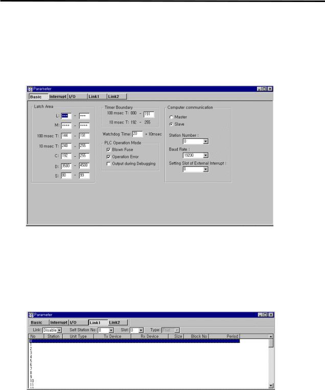
6. Communication Function
6.1.3 Parameter setting of high speed link
, : !"# - , 9
.
) ; : !"# 6-/-)-) : :-
Fig. 6.1.1 Standard screen of KGL project(for K200S)
2 , % # ; , # ) !"# : 6-/-)-)
# ; 6-/-)-2-
Fig. 6.1.2 Standard screen of link parameter
 Loading...