


Internal Use Only
http://biz.lgservice.com
Room Air Conditioner
SVC MANUAL(Exploded View)
MODEL : LWJ0515PCW/CG
LWJ0514PCF
LWJ0512PGG/CW/CG
LWC071JGMK0
LWC051JGMK1/JPMK2
LWC061JPMK0
LWJ0611PCG
CAUTION
Before Servicing the unit, read the safety precautions in General SVC manual. Only for authorized service personnel.

CONTENTS |
|
1. PREFACE ....................................................................................................................................................................... |
2 |
1.1 FEATURES ........................................................................................................................................................................ |
2 |
1.2 SPECIFICATIONS ............................................................................................................................................................. |
3 |
1.3 SAFETY PRECAUTIONS ................................................................................................................................................. |
3 |
1.4 INSULATION RESISTANCE TEST .................................................................................................................................... |
3 |
1.5 LOCATIONS OF CONTROLS ........................................................................................................................................... |
4 |
2. DISASSEMBLY INSTRUCTIONS .................................................................................................................... |
6 |
2.1 MECHANICAL PARTS ...................................................................................................................................................... |
6 |
2.1.1 FRONT GRILLE ....................................................................................................................................................... |
6 |
2.1.2 CABINET................................................................................................................................................................... |
6 |
2.1.3 CONTROL BOARD ................................................................................................................................................... |
6 |
2.2 AIR HANDLING PARTS .................................................................................................................................................... |
7 |
2.2.1 AIR GUIDE UPPER................................................................................................................................................... |
7 |
2.2.2 ORIFICE, TURBO FAN AND FAN............................................................................................................................. |
7 |
2.2.3 MOTOR .................................................................................................................................................................... |
8 |
2.2.4 AIR GUIDE ................................................................................................................................................................ |
8 |
2.3 ELECTRICAL PARTS ....................................................................................................................................................... |
8 |
2.3.1 OVERLOAD PROTECTOR ...................................................................................................................................... |
8 |
2.3.2 COMPRESSOR ........................................................................................................................................................ |
9 |
2.3.3 CAPACITOR ............................................................................................................................................................. |
9 |
2.3.4 THERMISTOR........................................................................................................................................................... |
9 |
2.3.5 CONTROL PANEL..................................................................................................................................................... |
9 |
2.3.6 POWER CORD ...................................................................................................................................................... |
10 |
2.4 REFRIGERANT CYCLE ............................................................................................................................................ |
10 |
2.4.1 CONDENSER ........................................................................................................................................................ |
10 |
2.4.2 EVAPORATOR ....................................................................................................................................................... |
10 |
2.4.3 CAPILLARY TUBE ................................................................................................................................................. |
11 |
3. INSTALLATION ......................................................................................................................................................... |
13 |
3.1 SELECT THE BEST LOCATION ..................................................................................................................................... |
13 |
3.2 HOW TO INSTALL .......................................................................................................................................................... |
13 |
3.3 ELECTRICAL DATA ..................................................................................................................................................... |
16 |
4. TROUBLESHOOTING GUIDE ........................................................................................................................ |
16 |
4.1 OUTSIDE DIMENSIONS ................................................................................................................................................. |
16 |
4.2 PIPING SYSTEM ............................................................................................................................................................ |
17 |
4.3 TROUBLESHOOTING GUIDE ........................................................................................................................................ |
18 |
5. SCHEMATIC DIAGRAM ...................................................................................................................................... |
26 |
5.1 CIRCUIT DIAGRAM......................................................................................................................................................... |
26 |
5.2 ELECTRONIC CONTROL DEVICE ................................................................................................................................. |
27 |
5.3 COMPONENTS LOCATION(FOR MAIN P.W.B ASM)............................................................................................................... |
28 |
5.4 COMPONENTS LOCATION(FOR DISPLAY P.W.B ASM) ......................................................................................................... |
28 |
6. EXPLODED VIEW ................................................................................................................................................... |
29 |
Copyright ©2007 LG Electronics. Inc. All right reserved. |
- 2 - |
Only for training and service purposes |
LGE Internal Use Only |
|
1. PREFACE
This service manual provides various service information, including the mechanical and electrical parts, etc. This room air conditioner was manufactured and assembled under a strict quality control system.
The refrigerant is charged at the factory. Be sure to read the safety precautions prior to servicing the unit.
1.1 FEATURES
•DESIGNED FOR COOLING ONLY
•POWERFUL AND INCREDIBLE COOLING
•TOP-DOWN CHASSIS FOR THE SIMPLE INSTALLATION AND SERVICE
•WASHABLE ONE-TOUCH FILTER
•COMPACT SIZE
1.2 SPECIFICATIONS
MODELS |
WG5200ER |
|
|
|
WG5200R |
|
|
LW5200ER |
|
|
|
ACQ052PK |
WG6000R |
|
|
|
|
|
|
|
|||
|
HBLG5200E |
LW050CE |
|
M5404R |
M6004R |
LW7000R |
|
|
LWC051JGMK2 |
|
WM5031 |
KG6000R |
|||
|
|
|
|
|
|||
ITEMS |
KG5200ER |
|
|
|
LWJ0515PAG |
HBLG6000R |
|
ACQ058PL |
|
|
|
LW5200R |
|
|
|
COOLING CAPACITY (BTU/h) |
5,200 |
5,050 |
|
5,250 |
6,000 |
76,000 |
|
|
|
|
|
|
|
|
|
POWER SUPPLY (Phase, V, Hz) |
|
|
|
|
1ø, 115V, 60HZ |
|
|
|
|
|
|
|
|
|
|
INPUT (W) |
470/480 |
520 |
|
|
540 |
620 |
720 |
|
|
|
|
|
|
|
|
OPERATING CURRENT (AMP.) |
4.3/4.4 |
4.8 |
|
|
5.0 |
5.8 |
6.7 |
|
|
|
|
|
|
|
|
REFRIGERANT CONTROL |
|
|
|
CAPILLARY TUBE |
|
||
|
|
|
|
|
|
||
REFRIGERANT CHARGE (R-22) |
330g (11.6 Oz) |
220g(7.8 Oz) |
235g (8.3 Oz) |
315g (11.1 Oz) |
|||
|
|
|
|
|
|
|
|
INSIDE FAN |
|
|
|
|
TURBO |
|
|
|
|
|
|
|
|
||
OUTSIDE FAN |
|
PROPELLER FAN WITH SLINGER RING |
|
||||
|
|
|
|
|
|
|
|
AIR DISCHARGE |
|
|
2-WAY (RIGHT AND LEFT) |
|
|||
|
|
|
|
|
|
|
|
CHASSIS |
|
|
|
|
TOP-DOWN |
|
|
|
|
|
|
|
|
||
PROTECTOR |
• OVERLOAD PROTECTOR FOR COMPRESSOR |
|
|||||
• INTERNAL PROTECTOR FOR FAN MOTOR |
|
||||||
|
|
||||||
|
|
|
|
|
|
|
|
TEMPERATURE CONTROL |
|
|
|
|
THERMISTOR |
|
|
|
|
|
|
|
|
||
ROTARY SWITCH |
5 POSITIONS (LOW FAN, HIGH FAN, OFF, HIGH COOL, LOW COOL) |
||||||
|
|
|
|
|
|
||
FAN MOTOR |
6 POLES, 21W |
6 POLES, 19W |
6 POLES, 21W |
6 POLES, 27W |
|||
|
|
|
|
|
|
|
|
• NOTE: Specifications are subject to minor change without notice for further improvement.
1.3 SAFETY PRECAUTIONS
1.When servicing, set the POWER of CONTROL BOARD to Off and unplug the power cord.
2.Observe the original lead dress.
If a short circuit is found, replace all parts which have been overheated or damaged by the short circuit.
3.After servicing, make an insulation resistance test to prevent the customer's exposure to shock hazards.
1.4 INSULATION RESISTANCE TEST
1.Unplug the power cord and connect a jumper between 2 pins (black and white).
2.The grounding conductor (green or green and yellow) is to be open.
3.Measure the resistance value with an ohm meter between the jumpered lead and each exposed metallic part on the equipment at all Mode [except POWER OFF].
4.The value should be over 1 MΩ.
Copyright ©2007 LG Electronics. Inc. All right reserved. |
- 3 - |
Only for training and service purposes |
LGE Internal Use Only |
|
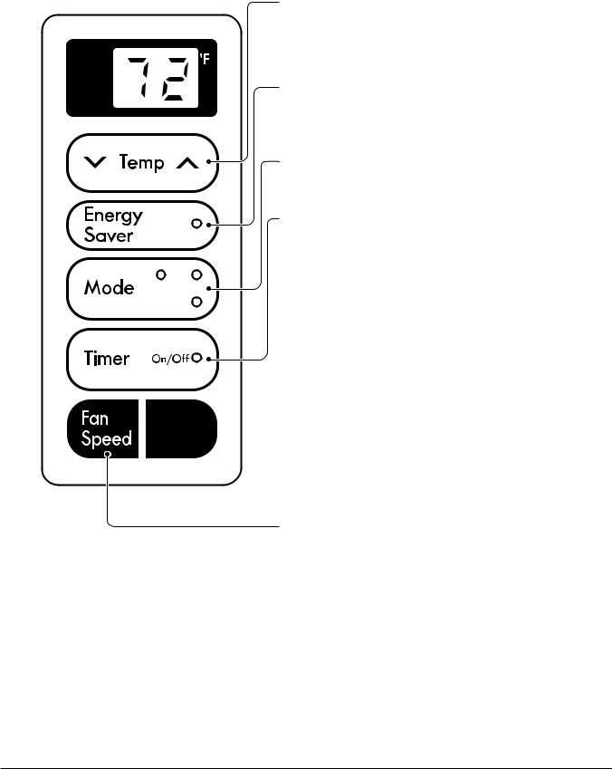
1.5 LOCATIONS OF CONTROLS
1.5.1 CONTROLS
TEMPERATURE SETTING
• This button can automatically control the temperature
of the room. The temperature can be set within a range of 60°F(16°C) to 86°F(30°C) by 1°F(1°C).
Select the lower number for lower temperature of the room.
ENERGY SAVER
The fan stops when the compressor stops cooling.
• Approximately every 3 minutes the fan will turn on and check the room air to determine if cooling is needed.
MODE
• Everytime you push this button, it will toggle between COOL, FAN, DRY or FAN, COOL.
ON/OFF TIMER
Dry Fan
Cool
- STOPPING OPERATION
•Everytime you push this button, when the unit is operating, timer is set as follows.
(1Hour  2Hours
  3Hours
  4Hours
 5Hours
 6Hours
7Hours  8Hours
  9Hours
  10Hours
  11Hours
  12Hours
  Cancel)
•The Setting Temperature will be raised by 2°F(1°C) 30min. later and by 2°F(1°C) after another 30 min.
- STARTING OPERATION
• Everytime you push this button, when the unit is not operating, timer is set as follow.
(1Hour  2Hours
  3Hours
  4Hours
 5Hours
 6Hours
7Hours 8Hours
  9Hours
  10Hours
  11Hours
  12Hours
  Cancel)


 POWER
POWER
•To turn the unit ON, push the button. To turn the unit OFF, push the button again.
•This button takes priority over any other buttons.
•When you first turn it on, the unit is on the High cool mode and the temp. at 72°F(22°C).
FAN SPEED
•Everytime you push this button it is set as follows. {High(F2)  Low(F1)
  High(F2)...} or
{High(F3)  Mid(F2)
  Low(F1)
  High(F3)...}.
Copyright ©2007 LG Electronics. Inc. All right reserved. |
- 4 - |
Only for training and service purposes |
LGE Internal Use Only |
|
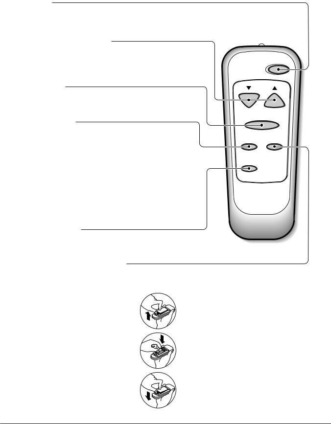
1.5.2 REMOTE CONTROLLER
POWER
•To turn the Set ON, push the button. To turn the Set OFF, push the button again.
•This button takes priority over any other buttons.
•When you first turn it on, the Set is on the High cool mode and the temp. at 72°F(22°C).
TEMPERATURE SETTING
•This button can automatically control the temperature of the room. The temperature can be set within a range of 60°F(16°C) to 86°F(30°C) by 1°F(1°C).
Select the lower number for lower temperature of the room.
FAN SPEED
•Everytime you push this button it is set as follows. {High(F2)  Low(F1)
  High(F2) or
{High(F3)  Mid(F2)
  Low(F1)
  High(F3)...}
ON/OFF TIMER
- STOPPING OPERATION
•Everytime you push this button, when the set is operating, timer is set as follows.
(1Hour  2Hours
  3Hours
  4Hours
  5Hours
  6Hours
7Hours  8Hours
  9Hours
  10Hours
  11Hours
  12Hours
 Cancel)
•The Setting Temperature will be raised by 2°F(1°C) 30min. later and by 2°F(1°C) after another 30 min.
- STARTING OPERATION
• Everytime you push this button, when the set is not operating, timer is set as follow.
(1Hour  2Hours
  3Hours
  4Hours
 5Hours
  6Hours
7Hours  8Hours
  9Hours
  10Hours
  11Hours
  12Hours
  Cancel)
ENERGY SAVER
The fan stops when the compressor stops cooling.
•Approximately every 3 minutes the fan will turn on and check the room air to determine if cooling is needed.
COOL/FAN/DRY or COOL/FAN
• Everytime you push this button, it will toggle between COOL, FAN and DRY.
Power
Temp
Fan Speed
Timer Mode
Energy
Saver
How to Insert Batteries
1.Remove the cover from the back of the remote controller
2.Insert two batteries.
•Be sure that the (+) and (-) directions are correct.
•Be sure that both batteries are new.
3.Re-attach the cover.
•Do not use rechargeable batteries. Such batteries
differ from standard dry cells in shape, dimensions, and performance.
•Remove the batteries from the remote controller if the air conditioner is not going to be used for an extended length of time.
Copyright ©2007 LG Electronics. Inc. All right reserved. |
- 5 - |
Only for training and service purposes |
LGE Internal Use Only |
|
2. DISASSEMBLY INSTRUCTIONS
2.1 MECHANICAL PARTS
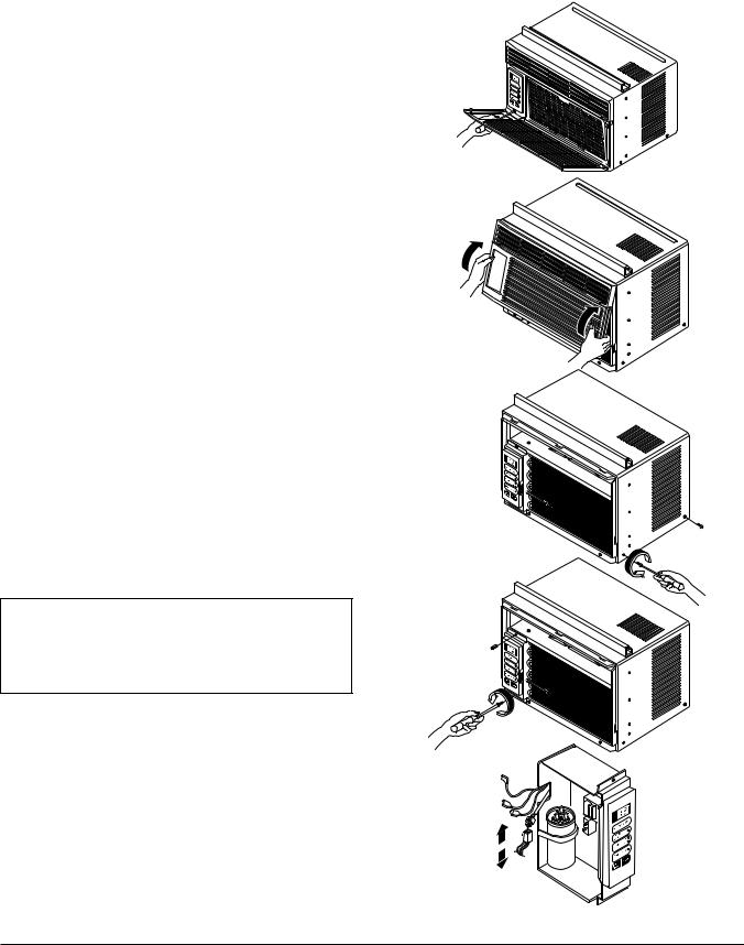
2.1.1 FRONT GRILLE Figure 1
1.Disconnect the unit from source of power.
2.Using a screwdriver, remove the screw that
secures the front grille to control board. (See Figure 1)
3. Push the front grille up from the bottom. Pull the top of the front grille away from the cabinet as the top tabs lift out of their slots. (See Figure 2)
4.Replace the grille by placing the tabs in the slots and push the grille until it snaps into place.
Figure 2
2.1.2 CABINET
1. Disconnect the unit from the power source.
2. Remove the front grille. (Refer to section 2.1.1) 3. Remove 9 screws that secure the cabinet to the
base pan and condenser. (See Figure 3)
4. Lift the cabinet from the unit.
Figure 3
5. Re-install by referring to the procedures above.
2.1.3 CONTROL BOARD
1.Disconnect the unit from the power source.
2.Remove the front grille. (Refer to Section 2.1.1)
3.Remove the cabinet. (Refer to Section 2.1.2)
4.Remove 2 screws that secure the control board to base pan and air guide. (See Figure 4)
5.Pull the control board toward yourself.
NOTE : Controls, wires, and capacitor are now accessible for servicing. Discharge the capacitor before servicing. See step
2.3.3on page 9 for procedures.
6.Disconnect one housing terminal and 3 wires for the fan motor and compressor. (See Figure 5)
7.Re-install components by referring to procedures above. (Refer to circuit diagram on page 26 in this manual or inside control board.)
Figure 4
Figure 5
Copyright ©2007 LG Electronics. Inc. All right reserved. |
- 6 - |
Only for training and service purposes |
LGE Internal Use Only |
|

2.2 AIR HANDLING PARTS |
Figure 6 |
2.2.1 AIR GUIDE UPPER
1. Disconnect the unit from the power source.
2. Remove the front grille. (Refer to Section 2.1.1)
3. Remove the cabinet. (Refer to Section 2.1.2)
4. Remove the control board. (Refer to Section 2.1.3)
5. Remove 2 screws that secure the brace to air guide upper and shroud. (See Figure 6)
6. Remove 2 screws that secure the air guide upper to air guide lower. (See Figure 6)
7.Lift air guide upper upward.
8.Re-install by referring to the procedures above.
Figure 7
2.2.2 ORIFICE, TURBO FAN AND FAN
1.Disconnect the unit from the power source.
2.Remove the front grille. (Refer to Section 2.1.1)
3.Remove the cabinet. (Refer to Section 2.1.2)
4.Remove the control board. (Refer to Section 2.1.3)
5.Remove the air guide upper. (Refer to Section 2.2.1)
6.Remove 2 screws that secure the base pan to condenser. (See Figure 7)
7.Remove 2 screws that secures the shroud to channel of condenser.
8.Press the snap area of shroud with your thumbs. This allows you to remove it from the condenser.
9.Lift the compressor upward with the evaporator and condenser. (See Figure 7)
10.Remove the orfice by pushing the snap area of the air guide blower. (See Figure 8)
11.Remove the clamp springs which are clamped to the boss of fan and turbo fan by hand plier. (See Figure 9)
12.Pull the fan and turbo fan outward.
13.Remove the shroud.
14.Re-install by referring to the procedures above.
Figure 8
Figure 9
Copyright ©2007 LG Electronics. Inc. All right reserved. |
- 7 - |
Only for training and service purposes |
LGE Internal Use Only |
|
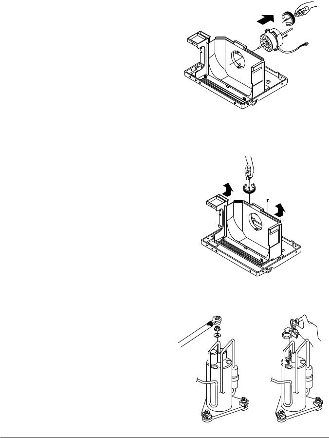
2.2.3 MOTOR
1.Disconnect the unit from the power source.
2.Remove the front grille. (Refer to Section 2.1.1)
3.Remove the cabinet. (Refer to Section 2.1.2)
4.Remove the control board. (Refer to Section 2.1.3)
5.Remove the air guide upper. (Refer to Section 2.2.1)
6.Remove the compressor, turbo fan, fan and shroud. (Refer to Section 2.2.2)
7.Remove 2 screws that secure the motor to the motor. (See Figure 10)
8.Remove the motor.
9.Re-install by referring to the procedures above.
2.2.4 AIR GUIDE
1.Disconnect the unit from the power source.
2.Remove the front grille. (Refer to Section 2.1.1)
3.Remove the cabinet. (Refer to Section 2.1.2)
4.Remove the control board. (Refer to Section 2.1.3)
5.Remove the air guide upper. (Refer to Section 2.2.1)
6.Remove the compressor, turbo fan, fan and shroud. (Refer to Section 2.2.2)
7.Remove the motor. (Refer to Section 2.2.3)
8.Remove 2 screws that secure the air guide to the base pan. (See Figure 11)
9.Push the air guide backward and lift it upward. (See Figure 11)
10.Re-install by referring to the procedures above.
2.3ELECTRICAL PARTS
2.3.1 OVERLOAD PROTECTOR
1.Remove the front grille and cabinet. (Refer to Section 2.1)
2.Remove the nut which fastens the terminal cover.
3.Remove the terminal cover.
4.Remove all the leads from the overload protector.
5.Remove the overload protector.
6.Re-install the components by referring to the removal procedure above.
(See Figure 12 and 13)
Figure 10
Figure 11
Figure 12 |
Figure 13 |
|
Copyright ©2007 LG Electronics. Inc. All right reserved. |
- 8 - |
Only for training and service purposes |
LGE Internal Use Only |
|

2.3.2 COMPRESSOR
1.Remove the front grille and cabinet. (Refer to Section 2.1.2)
2.Discharge the refrigerant by using a refrigerant recovery system.
3.Remove the overload protector. (Refer to Section 2.3.1)
4.After discharging the unit completely, unbrace the suction and discharge pipes at the compressor connections.
5.Remove 3 nuts which fasten the compressor.
6.Remove the compressor.
7.Re-install by referring to the removal procedure above. (See Figure 14)
2.3.3 CAPACITOR
1.Remove the cabinet. (Refer to Section 2.1.2)
2.Remove the control board. (Refer to Section 2.1.3)
3.Discharge the capacitor by placing a 20 KΩ resistor across the capacitor terminals.
4.Pull the capacitor upward.
5.Remove all the leads of capacitor terminals.
6.Re-install the components by referring to the removal procedure above. (See Figure 15)
Figure 14
Figure 15
2.3.4 THERMISTOR
1.Remove the cabinet. (Refer to Section 2.1.2)
2.Remove the control board. (Refer to Section 2.1.3)
3.Disconnect the thermistor terminals from main P.W.B assembly.
4.Remove the thermistor.
5.Re-install the components by referring to the removal procedure above. (See Figure 16)
2.3.5 CONTROL PANEL
1.Remove the cabinet. (Refer to Section 2.1.2)
2.Remove the control board. (Refer to Section 2.1.3)
3.Pull the control panel forward and pull out it.
4.Remove 2 lead wire terminals.
5.Re-install the components by referring to the removal procedure above. (See Figure 17)
Figure 16
Figure 17
Copyright ©2007 LG Electronics. Inc. All right reserved. |
- 9 - |
Only for training and service purposes |
LGE Internal Use Only |
|
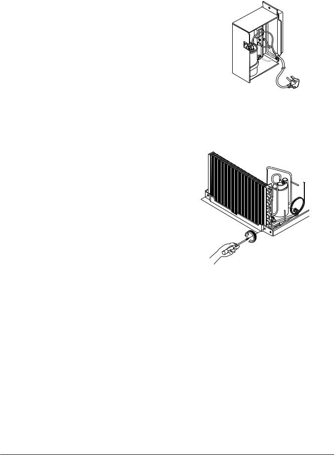
2.3.6 POWER CORD
1.Disconnect the unit from source of power.
2.Remove the front grille. (Refer to Section 2.1.1)
3.Remove the cabinet. (Refer to Section 2.1.2)
4.Remove 2 screws that secure control board to base pan and air guide. (Refer to Section 2.1.3)
5.Pulls the control board toward you.
6.Remove the grounding screw.
7.Remove a screw securing the clip with cord to the control board.
8.Pull the power cord.
9.Re-install by referring to procedures above.
2.4 REFRIGERANT CYCLE
2.4.1 CONDENSER
1.Remove the cabinet. (Refer to Section 2.1.2)
2.Discharge the refrigerant by using a refrigerant recovery system.
3.Remove 2 screws which fasten the condenser. (See Figure 19)
4.After discharging the refrigerant completely, unbraze the interconnecting tube at the condenser connections.
5.Remove the condenser.
6.Re-install by referring to the procedures above.
2.4.2 EVAPORATOR
1.Remove the cabinet. (Refer to Section 2.1.2)
2.Discharge the refrigerant by using a refrigerant recovery system.
3.Remove the air guide upper. (Refer to Section 2.2.1)
4.After discharging the refrigerant completely, unbraze the interconnecting tube at the evaporator connections.
5.Remove the evaporator.
6.Re-install by referring to the procedures above.
Figure 18
Figure19
Copyright ©2007 LG Electronics. Inc. All right reserved. |
- 10 - |
Only for training and service purposes |
LGE Internal Use Only |
|
 Loading...