


LG 42LH30FR, 22LU40R, 32LF20FR, 32SL80YR, 42LH50YR Owner's Manual
...
|
|
|
User’s’s Guidei Specificationifi ti |
|
|
|
||
|
|
|
|
|||||
|
|
|
|
|
|
|
|
|
|
|
|
|
|
|
|
Yang HM |
KANG |
|
|
|
|
|
|
|
||
1. Model Description |
|
|
|
|||||
|
|
|
KWANG SUK |
|||||
|
|
|
09.02.16 |
|||||
|
|
|
|
|
|
|
09.02.16 |
|
|
|
|
|
|
|
|
|
|
MODEL |
LH20R-MA |
BRAND |
LG |
Part No. |
MFL58486305 |
|||
|
|
|
|
|
|
|
||
|
|
|
|
|
LH20R/LF20FR/LU40R |
|||
SUFFIX |
Latin America |
Product Name |
|
(0910-REV10) |
||||
|
|
|
/LH30FR/LU50R_FR/LH70YR |
|
|
|||
2.Printing Specification
1.Trim Size (Format) : 185mm x 260 mm
2.Printing Colors
•Cover : 1 COLOR (BLACK)
•Inside : 1 COLOR (BLACK) 3. Stock (Paper)
•Cover : Coated paper , S/White 150 g/
•Inside : Uncoated paper , 60 g/
4. Printing Method : Off set
5. Bindery : Perfect bind
6. Language : English/Spanish (2)
7. Number of pages : 252
“This part contain Eco-hazardous substances (Pb, Cd, Hg, Cr6+, PBB, PBDE, etc.) within LG standard level,
NDetails should be followed Eco-SCM management standard[LG(56)-A-2524].
OEspecially, Part should be followed and controlled the following specification.
T(1)Eco-hazardous substances test report should be submitted
Ewhen Part certification test and First Mass Production.
S(2) Especially, Don’t use or contain lead(Pb) and cadmium(Cd) in ink.
3.Special Instructions
(1)Origin Notification
* LGEMX : Printed in Mexico |
* LGENT : Printed in China |
* LGEMA : Printed in Poland |
* LGETH : Printed in Thailand |
* LGERS : Printed in Mexico |
* LGENP : Printed in China |
* LGEWA : Printed in U.K. |
* LGEVN : Printed in Vietnam |
* LGEAZ : Printed in Brazil |
* LGEIL : Printed in India |
* LGEEG : Printed in Egypt |
|
* LGESP : Printed in Brazil |
* LGEDI : Printed in Indonesia |
* LGERA : Printed in Russia |
|
* LGESY : Printed in China |
* LGEIN : Printed in Indonesia |
* LGEAK : Printed in Kazakhstan |
|
4.Changes
9 |
Sep/01/09 |
SHIN M.J |
S9-59957 |
Added the model LU40R-MC, SL90QR-MA. |
|
||
8 |
Aug./10/09 |
Park Sun Young |
S9-59429 |
Applied the model LH90QR-MA, SL80YR-MA PQ test results. |
|
||
7 |
May/28/09 |
Yang Hyo Mi |
S9-53993 |
Applied the model LH50YR PQ test results. |
|
||
6 |
April./20/09 |
Yang Hyo Mi |
S9-50494 |
Added the screw for stand fixing on the 32/42LF20FR-MA models. |
|||
|
|
|
|
|
|
|
|
5 |
April./09/09 |
Yang Hyo Mi |
S9-49460 |
Added the model LF20FR-MA, LU50R/FR-MA/B. |
|||
|
|
|
|
|
|
|
|
4 |
April./01/09 |
Yang Hyo Mi |
S9-48260 |
Corrected the DivX logo. |
|
||
3 |
Mar./13/09 |
Yang Hyo Mi |
S9-46784 |
Corrected the size of the LH30FR-MA and corrected the USB |
|||
|
|
|
|
part. |
|
||
2 |
Mar./07/09 |
Yang Hyo Mi |
S9-45359 |
Changed the RGB-PC resolution and corrected the Bluetooth, |
|||
USB functions. |
|
||||||
|
|
|
|
||||
1 |
Feb./24/09 |
Yang Hyo Mi |
S9-44529 |
Revised the revision. |
|
||
REVNO.. MM/DD/YY |
SIGNATURE |
CHANGE NO. |
CHANGE CONTENTS |
|
|||
4.Changes (Continued)
18 |
|
|
|
|
17 |
|
|
|
|
|
|
|
|
|
16 |
|
|
|
|
|
|
|
|
|
15 |
|
|
|
|
|
|
|
|
|
14 |
|
|
|
|
13 |
|
|
|
|
12 |
|
|
|
|
|
|
|
|
|
11 |
|
|
|
|
|
|
|
|
|
10 |
Oct/16/09 |
SHIN M.J |
S9-64187 |
Added precaution for USB and RS-232C and changed product |
|
|
|
|
specifications for 55SL80YR. |
REV. MM/DD/YY |
SIGNATURE |
CHANGE NO. |
CHANGE CONTENTS |
|
NO. |
|
|
|
|
P/NO.MFL58486305
Total pages : 252 pages
Paginationi ti sheett
Front cover |
|
|
|
|
|
|
|
|
|
|
|
|
|
LG(EN) |
|||
|
|
|
|
|
|
|
|
|
|
|
|
|
|
||||
|
|
|
|
|
|
|
|
|
|
|
|
|
|
|
|
|
|
|
LG(EN) |
|
|
|
|
|
|
|
|
|
|
|
|
|
|
|
|
|
|
|
|
|
|
|
|
|
|
|
|
|
|
|
|
|
|
|
|
|
|
|
|
|
|
|
|
|
|
|
|
|
|
|
Rear cover |
|
P/NO. |
|
|
2 |
…. |
|
…. |
… |
|
|
124 |
125 |
|
|
|
||
|
|
|
|
|
|
|
|
|
|||||||||
|
|
|
|
|
|
|
|
|
|
|
|
|
|
|
|||
|
|
|
|
|
|
|
|
|
|
|
|
|
|
|
|
|
LG(SP) |
|
|
|
|
|
|
|
|
|
|
|
|
|
|
|
|
|
|
|
LG(SP) |
|
|
|
|
|
|
|
|
|
|
|
|
|
|
|
|
|
|
|
|
|
2 |
…. |
|
…. |
… |
|
|
124 |
125 |
|
|
|
|
|
|
|
|
|
|
|
|
|
|
|
|||||||
|
|
|
|
|
|
|
|
|
|
|
|
|
|
|
|
|
|

MFL58486305-Edit1-en 10/21/09 11:07 AM Page 1
LED LCD TV OWNER’S MANUAL
42LH90QR 42SL90QR 47LH90QR 47SL90QR
LCD TV
OWNER’S MANUAL
19LH20R |
32LH30FR |
19LU50R |
22LH20R |
37LH30FR |
22LU50FR |
26LH20R |
42LH30FR |
26LU50FR |
32LH20R |
47LH30FR |
|
37LH20R |
|
32SL80YR |
42LH20R |
42LH50YR |
42SL80YR |
|
47LH50YR |
47SL80YR |
32LF20FR |
55LH50YR |
55SL80YR |
42LF20FR |
|
|
|
32LH70YR |
|
22LU40R |
42LH70YR |
|
|
47LH70YR |
|
Please read this manual carefully before operating your set and retain it for future reference.
The model and serial number of the TV is located on the back and one side of the TV.
Record it below should you ever need service.
Model:
Serial:
P/NO : MFL58486305 (0910-REV10)
www.lge.com
MFL58486305-Edit1-en 10/21/09 11:07 AM Page 2
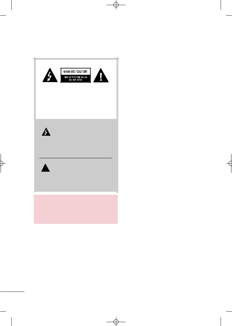
WARNING / CAUTION
TO REDUCE THE RISK OF ELECTRIC SHOCK DO NOT REMOVE COVER (OR BACK). NO USER SERVICEABLE PARTS INSIDE. REFER TO QUALIFIED SERVICE PERSONNEL.
The lightning flash with arrowhead  symbol, within an equilateral triangle, is intended to alert the user to the presence of uninsulated “dangerous voltage” within the
product’s enclosure that may be of sufficient magnitude to constitute a risk of electric shock to persons.
The exclamation point within an equilateral  triangle is intended to alert the user to the presence of important operating and maintenance (servicing) instructions in the
literature accompanying the appliance.
WARNING/CAUTION
TO REDUCE THE RISK OF FIRE AND ELECTRIC SHOCK, DO NOT EXPOSE THIS PRODUCT TO RAIN OR MOISTURE.
2
MFL58486305-Edit1-en 10/21/09 11:07 AM Page 3
SAFETY INSTRUCTIONS
IMPORTANT SAFETY INSTRUCTIONS
Read these instructions.
Keep these instructions.
Heed all warnings.
Follow all instructions.
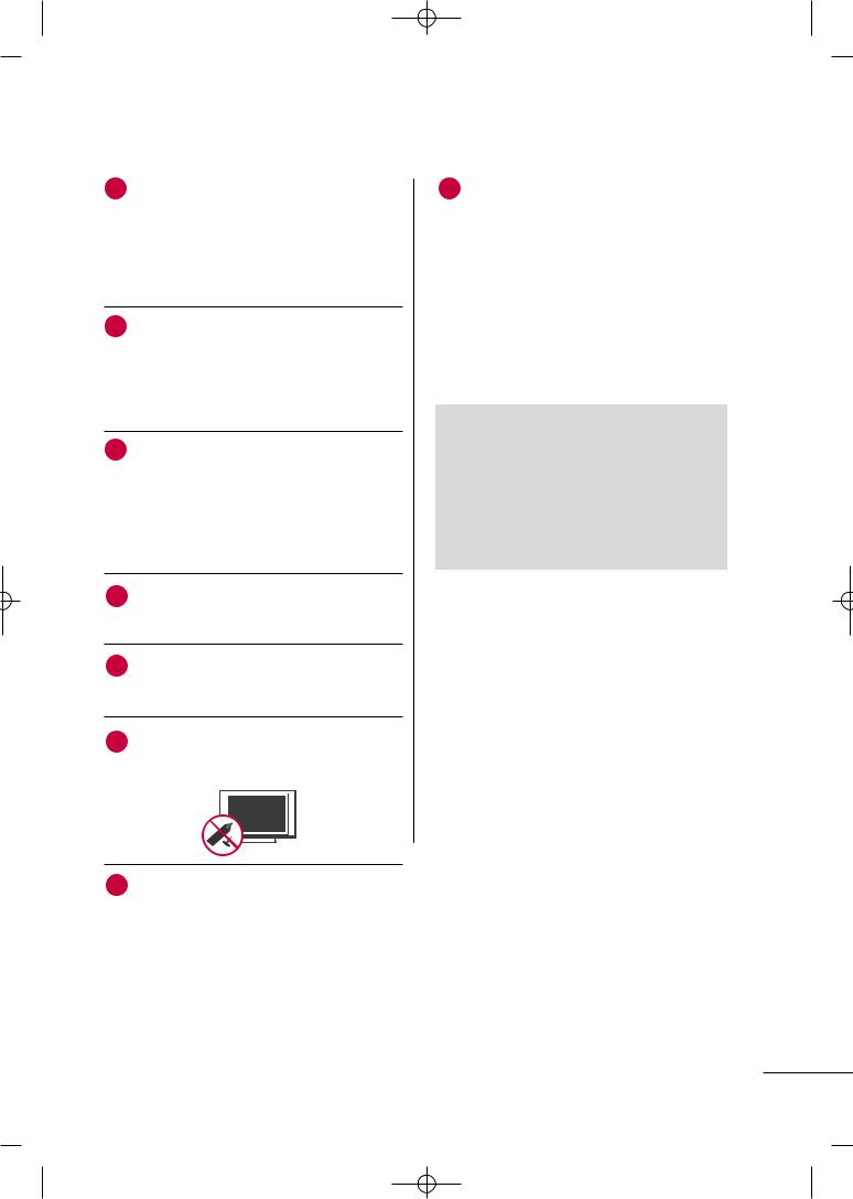
1
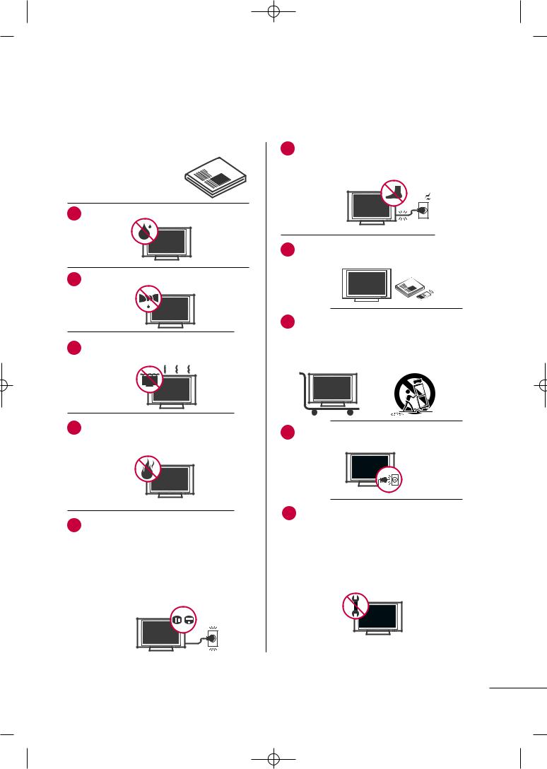
2Clean only with dry cloth.
3Do not block any ventilation openings. Install in accordance with the manufacturer’s instructions.
4Do not install near any heat sources such as radiators, heat registers, stoves, or other
apparatus (including amplifiers)that produce heat.
5Do not defeat the safety purpose of the polarized or grounding-type plug. A polarized plug has
two blades with one wider than the other. A grounding type plug has two blades and a third grounding prong, The wide blade or the third prong are provided for your safety. If the provided plug does not fit into your outlet, consult an electrician for replacement of the obsolete outlet.
6Protect the power cord from being walked on or pinched particularly at plugs, convenience
receptacles, and the point where they exit from the apparatus.
Only use attachments/accessories specified by the manufacturer.
Use only with the cart, stand, tripod, bracket, or table specified by the manufacturer, or sold with the apparatus. When a cart is used, use caution when moving the cart/apparatus combination to avoid injury from tip-over.
9Unplug this apparatus during lighting storms or when unused for long periods of time.
10 |
Refer all servicing to qualified service personnel. |
|
Servicing is required when the apparatus has |
been damaged in any way, such as powersupply cord or plug is damaged, liquid has been spilled or objects have fallen into the apparatus, the apparatus has been exposed to rain or moisture, does not operate normally, or has been dropped.
3
MFL58486305-Edit1-en 10/21/09 11:07 AM Page 4
SAFETY INSTRUCTIONS
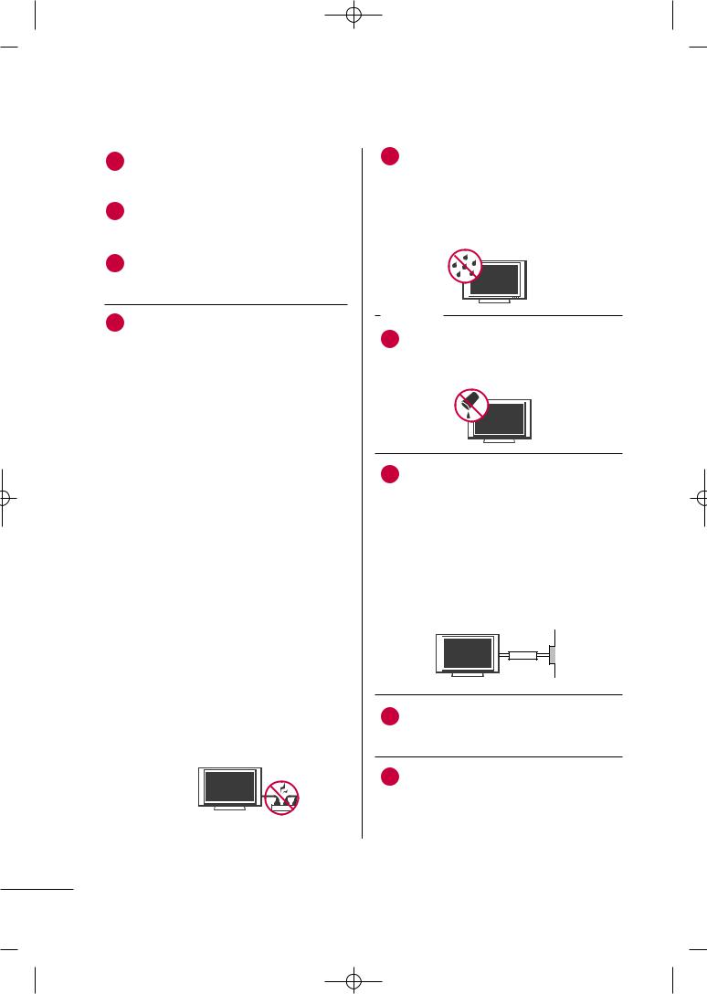
11 |
Never touch this apparatus or antenna during |
a thunder or lighting storm. |
|
|
|
|
When mounting a TV on the wall, make sure |
|
signal cables on the back of the TV. |
|
|
13 |
Do not allow an impact shock or any objects to |
fall into the product, and do not drop onto the screen with something.
CAUTION concerning the Power Cord:
upon a dedicated circuit; that is, a single outlet circuit which powers only that appliance and has no additional outlets or branch circuits. Check the specification page of this owner's manual to be certain.
Do not connect too many appliances to the same AC power outlet as this could result in fire or electric shock.
Do not overload wall outlets. Overloaded wall outlets, loose or damaged wall outlets, extension cords, frayed power cords, or damaged or cracked wire insulation are dangerous. Any of these conditions could result in electric shock or fire. Periodically examine the cord of your appliance, and if its appearance indicates damage or deterioration, unplug it, discontinue use of the appliance, and have the cord replaced with an exact replacement part by an authorized servicer. Protect the power cord from physical or mechanical abuse, such as being twisted, kinked, pinched, closed in a door, or walked upon. Pay particular attention to plugs, wall outlets, and the point where the cord exits the appliance.
Do not make the TV with the power cord plugged in. Do not use a damaged or loose power cord. Be sure do grasp the plug when unplugging the power cord. Do not pull on the power cord to unplug the TV.
15 |
of fire or electrical |
|
product to rain, |
moisture or other liquids. Do not touch the TV with wet hands. Do not install this product flammable objects such as gasoline or or expose the TV to direct air
conditioning.
Do not expose to dripping or splashing and do not place objects filled with liquids, such as vases, cups, etc. on or over the apparatus (e.g. on shelves above the unit).
GROUNDING
Ensure that you connect the earth ground wire to prevent possible electric shock (i.e. a TV with a three-prong grounded AC plug must be connected to a three-prong grounded AC outlet). If grounding methods are not possible, have a qualified electrician install a separate circuit breaker.
Do not try to ground the unit by connecting it to telephone wires, lightening rods, or gas pipes.
Power
Supply
Short-circuit
Breaker
18 DISCONNECTING DEVICE FROM MAINS Mains plug is the disconnecting device. The plug must remain readily operable.
19 As long as this unit TV is connected to the AC wall outlet, it is not disconnected from the AC power source even if you turn off this unit by SWITCH.
4
MFL58486305-Edit1-en 10/21/09 11:07 AM Page 5
20
scrub gently with a soft cloth to prevent scratching. Do not spray water or other liquids directly on the TV as electric shock may occur. Do not clean with chemicals such as alcohol, thinners or benzene.
Moving
Make sure the product is turned off, unplugged and all cables have been removed. It may take 2 or more people to carry larger TVs. Do not press against or put stress on the front panel of the TV.
Ventilation
Install your TV where there is proper ventilation. Do not install in a confined space such as a bookcase. Do not cover the product with cloth or other materials (e.g.) plastic while plugged in. Do not install in excessively dusty places.
23 Take care not to touch the ventilation openings. When watching the TV for a long period, the ventilation openings may become hot.
If you smell smoke or other odors coming from the TV or hear strange sounds, unplug the power cord contact an authorized service center.
pen, or make a scratch on it.
26 Keep the product away from direct sunlight.
27 |
be |
|
is |
||
|
||
|
normal, there is nothing wrong with TV. |
|
|
Some minute dot defects may be visible on the |
|
|
screen, appearing as tiny red, green, or blue |
|
|
spots. However, they have no adverse effect on |
|
|
the monitor's performance. |
|
|
Avoid touching the LCD screen or holding your |
|
|
finger(s) against it for long periods of time. |
|
|
Doing so may produce some temporary dis- |
|
|
tortion effects on the screen. |
DISPOSAL (Some models)
Hg lamp used LCD TV)
fluorescent lamp used in this product contains amount of mercury. Do not dispose of product with general household waste. of this product must be carried out in to the regulations of your local authority.
5
MFL58486305-Edit1-en 10/21/09 11:07 AM Page 6
CONTENTS |
|
WARNING / CAUTION . . . . . . . . . . . . . . . . . . . . . . . . . . . |
. 2 |
SAFETY INSTRUCTIONS . . . . . . . . . . . . . . . . . . . . . . . . |
. . 3 |
FEATURE OF THIS TV . . . . . . . . . . . . . . . . . . . . . . . . . . . . . |
. . 8 |
PREPARATION |
|
Accessories . . . . . . . . . . . . . . . . . . . . . . . . . . . . . . . . . . . . . . . . . . . . . . . . . . . . . |
. 8 |
Front Panel Information . . . . . . . . . . . . . . . . . . . . . . . . . . . . . . . . . . . |
10 |
Back Panel Information . . . . . . . . . . . . . . . . . . . . . . . . . . . . . . . . . . . . |
15 |
Stand Instruction . . . . . . . . . . . . . . . . . . . . . . . . . . . . . . . . . . . . . . . . . . . . . |
19 |
VESA Wall Mounting . . . . . . . . . . . . . . . . . . . . . . . . . . . . . . . . . . . . . . . . |
27 |
Cable Arrangement . . . . . . . . . . . . . . . . . . . . . . . . . . . . . . . . . . . . . . . . . |
28 |
Desktop Pedestal Installation . . . . . . . . . . . . . . . . . . . . . . . . . . . |
31 |
Swivel Stand . . . . . . . . . . . . . . . . . . . . . . . . . . . . . . . . . . . . . . . . . . . . . . . . . . . . |
31 |
Positioning your display . . . . . . . . . . . . . . . . . . . . . . . . . . . . . . . . . . . |
31 |
Attaching the tv to a desk . . . . . . . . . . . . . . . . . . . . . . . . . . . . . . . . |
32 |
Kensington Security System . . . . . . . . . . . . . . . . . . . . . . . . . . . . . |
32 |
Securing the TV to the wall to prevent falling when |
|
the tv is used on a stand . . . . . . . . . . . . . . . . . . . . . . . . . . . . . . . . . |
33 |
Antenna or Cable Connection . . . . . . . . . . . . . . . . . . . . . . . . . . |
34 |
- Channel Editing . . . . . . . . . . . . . . . . . . . . . . . . . . . . . . . . . . . . . . . . 58
Channel List . . . . . . . . . . . . . . . . . . . . . . . . . . . . . . . . . . . . . . . . . . . . . . . . . . . . 59
Favorite Channel Setup . . . . . . . . . . . . . . . . . . . . . . . . . . . . . . . . . . . . 60
Favorite Channel List . . . . . . . . . . . . . . . . . . . . . . . . . . . . . . . . . . . . . . . 60
Input List . . . . . . . . . . . . . . . . . . . . . . . . . . . . . . . . . . . . . . . . . . . . . . . . . . . . . . . . 61
Input Label . . . . . . . . . . . . . . . . . . . . . . . . . . . . . . . . . . . . . . . . . . . . . . . . . . . . . 62
AV Mode . . . . . . . . . . . . . . . . . . . . . . . . . . . . . . . . . . . . . . . . . . . . . . . . . . . . . . . . 63
Key Lock . . . . . . . . . . . . . . . . . . . . . . . . . . . . . . . . . . . . . . . . . . . . . . . . . . . . . . . . . 63
SIMPLINK . . . . . . . . . . . . . . . . . . . . . . . . . . . . . . . . . . . . . . . . . . . . . . . . . . . . . . . 64
BLUETOOTH
Bluetooth? . . . . . . . . . . . . . . . . . . . . . . . . . . . . . . . . . . . . . . . . . . . . . . . . . . . . . . 66 Setting the bluetooth . . . . . . . . . . . . . . . . . . . . . . . . . . . . . . . . . . . . . . 67 Set TV PIN . . . . . . . . . . . . . . . . . . . . . . . . . . . . . . . . . . . . . . . . . . . . . . . . . . . . . 68 Bluetooth headset . . . . . . . . . . . . . . . . . . . . . . . . . . . . . . . . . . . . . . . . . . . 69
Managing Registered Bluetooth device . . . . . . . . . . . . . 71
My Bluetooth Information . . . . . . . . . . . . . . . . . . . . . . . . . . . . . . . 72
Viewing the photos with Bluetooth device . . . . . . . . 73 Listening the Musics with Bluetooth device . . . . . . . 73
EXTERNAL EQUIPMENT SETUP
HD Receiver Setup . . . . . . . . . . . . . . . . . . . . . . . . . . . . . . . . . . . . . . . . . 35
DVD Setup . . . . . . . . . . . . . . . . . . . . . . . . . . . . . . . . . . . . . . . . . . . . . . . . . . . . . 38
VCR Setup . . . . . . . . . . . . . . . . . . . . . . . . . . . . . . . . . . . . . . . . . . . . . . . . . . . . . 40
Other A/V Source Setup . . . . . . . . . . . . . . . . . . . . . . . . . . . . . . . . . 41
PC Setup . . . . . . . . . . . . . . . . . . . . . . . . . . . . . . . . . . . . . . . . . . . . . . . . . . . . . . . . 42
USB Connection . . . . . . . . . . . . . . . . . . . . . . . . . . . . . . . . . . . . . . . . . . . . . 45
Variable Out . . . . . . . . . . . . . . . . . . . . . . . . . . . . . . . . . . . . . . . . . . . . . . . . . . . 46
Monitor Out . . . . . . . . . . . . . . . . . . . . . . . . . . . . . . . . . . . . . . . . . . . . . . . . . . . 46
WATCHING TV / CHANNEL CONTROL
Remote Control Functions . . . . . . . . . . . . . . . . . . . . . . . . . . . . . . . 47
Turning On the TV . . . . . . . . . . . . . . . . . . . . . . . . . . . . . . . . . . . . . . . . . . 52
Channel Selection . . . . . . . . . . . . . . . . . . . . . . . . . . . . . . . . . . . . . . . . . . . 52
Volume Adjustment . . . . . . . . . . . . . . . . . . . . . . . . . . . . . . . . . . . . . . . . . 52
Initializing Setup (Mode Setting) . . . . . . . . . . . . . . . . . . . . . . 53
On-Screen Menus Selection . . . . . . . . . . . . . . . . . . . . . . . . . . . . 54
Quick Menu . . . . . . . . . . . . . . . . . . . . . . . . . . . . . . . . . . . . . . . . . . . . . . . . . . . . 55
Channel Setup
- Auto Scan (Auto Tuning) . . . . . . . . . . . . . . . . . . . . . . . . . . . 56
- Add / Delete Channel (Manual Tuning) . . . . . . 57
USB
Entry Modes . . . . . . . . . . . . . . . . . . . . . . . . . . . . . . . . . . . . . . . . . . . . . . . . . . . 74
Photo List . . . . . . . . . . . . . . . . . . . . . . . . . . . . . . . . . . . . . . . . . . . . . . . . . . . . . . . 75
Music List . . . . . . . . . . . . . . . . . . . . . . . . . . . . . . . . . . . . . . . . . . . . . . . . . . . . . . . 79
Movie List . . . . . . . . . . . . . . . . . . . . . . . . . . . . . . . . . . . . . . . . . . . . . . . . . . . . . . . 81
DivX Registration Code . . . . . . . . . . . . . . . . . . . . . . . . . . . . . . . . . . . 84
Deactivation . . . . . . . . . . . . . . . . . . . . . . . . . . . . . . . . . . . . . . . . . . . . . . . . . . . 85
PICTURE CONTROL
Picture Size (Aspect Ratio) Control . . . . . . . . . . . . . . . . . . 86
Preset Picture Settings - Picture Mode . . . . . . . . . . . . . 88
Manual Picture Adjustment - User Mode . . . . . . . . . . 89
Picture Improvement Technology . . . . . . . . . . . . . . . . . . . . . 90
Expert Picture control . . . . . . . . . . . . . . . . . . . . . . . . . . . . . . . . . . . . . . 91
 Energy Saving . . . . . . . . . . . . . . . . . . . . . . . . . . . . . . . . . . . . . . . . . . . . . 94
Picture Reset . . . . . . . . . . . . . . . . . . . . . . . . . . . . . . . . . . . . . . . . . . . . . . . . . . . 95
LED Local Dimming . . . . . . . . . . . . . . . . . . . . . . . . . . . . . . . . . . . . . . . . . 95
Power Indicator . . . . . . . . . . . . . . . . . . . . . . . . . . . . . . . . . . . . . . . . . . . . . . . 96
Demo Mode . . . . . . . . . . . . . . . . . . . . . . . . . . . . . . . . . . . . . . . . . . . . . . . . . . . 97
Initial Setting (Factory Reset) . . . . . . . . . . . . . . . . . . . . . . . . . . . 98
6
MFL58486305-Edit1-en 10/21/09 11:07 AM Page 7
SOUND & LANGUAGE CONTROL
Auto Volume Leveler (Auto Volume) . . . . . . . . . . . . . . . . . 99
Clear Voice ll . . . . . . . . . . . . . . . . . . . . . . . . . . . . . . . . . . . . . . . . . . . . . . . . . 100
Preset Sound Setting (Sound Mode) . . . . . . . . . . . . . . 101
Sound Setting Adjustment - User Mode
- SRS TruSurround XT . . . . . . . . . . . . . . . . . . . . . . . . . . . . . . . 102
Balance . . . . . . . . . . . . . . . . . . . . . . . . . . . . . . . . . . . . . . . . . . . . . . . . . . . . . . . . . 103
TV Speakers On/Off Setup . . . . . . . . . . . . . . . . . . . . . . . . . . . . 104
Selecting Audio Out . . . . . . . . . . . . . . . . . . . . . . . . . . . . . . . . . . . . . . 105
Audio Reset . . . . . . . . . . . . . . . . . . . . . . . . . . . . . . . . . . . . . . . . . . . . . . . . . 106
Stereo/SAP Broadcast Setup . . . . . . . . . . . . . . . . . . . . . . . . . . 107
On-Screen Menus Language Selection . . . . . . . . . . . . 108
Closed Captions . . . . . . . . . . . . . . . . . . . . . . . . . . . . . . . . . . . . . . . . . . . 109
TIME SETTING
Clock Setting
- Clock Setup . . . . . . . . . . . . . . . . . . . . . . . . . . . . . . . . . . . . . . . . . . . 110
Sleep Timer Setting . . . . . . . . . . . . . . . . . . . . . . . . . . . . . . . . . . . . . . . . 111
On/Off Time Setting . . . . . . . . . . . . . . . . . . . . . . . . . . . . . . . . . . . . . 112
APPENDIX
Troubleshooting . . . . . . . . . . . . . . . . . . . . . . . . . . . . . . . . . . . . . . . . . . . . . 113
Maintenance . . . . . . . . . . . . . . . . . . . . . . . . . . . . . . . . . . . . . . . . . . . . . . . . . . 115
Product Specifications . . . . . . . . . . . . . . . . . . . . . . . . . . . . . . . . . . . . 116
IR Codes . . . . . . . . . . . . . . . . . . . . . . . . . . . . . . . . . . . . . . . . . . . . . . . . . . . . . .119
External Control Through RS-232C . . . . . . . . . . . . . . . . .120
7
MFL58486305-Edit1-en 10/21/09 11:07 AM Page 8
FEATURE OF THIS TV
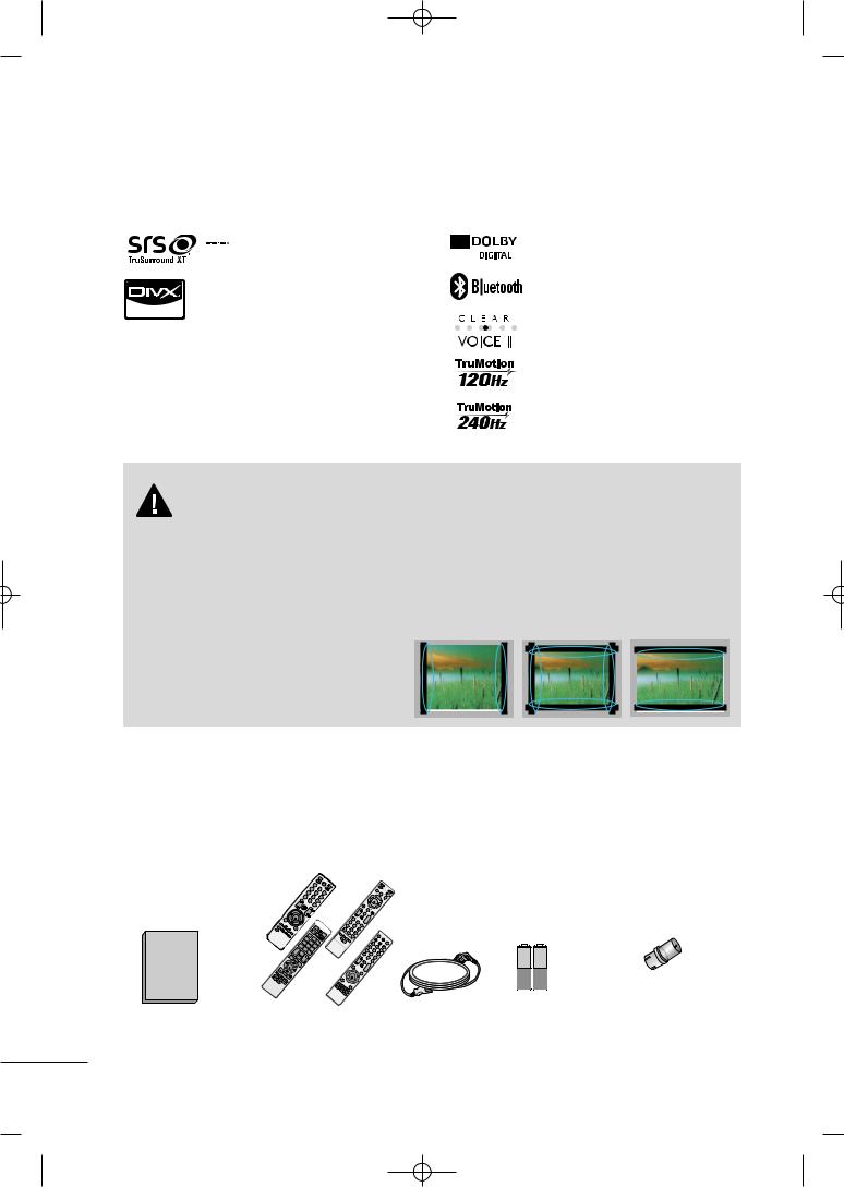
■ This feature is not available for all models.
 is a trademark of SRS Labs, Inc. TruSurround XT technology is incorporated under license from SRS Labs, Inc.
“DivX Certified to play DivX video, including premium content”
ABOUT DIVX VIDEO: DivX® is a digital video format created by DivX,Inc. This is an official DivX Certified device that plays DivX video. Visit www.divx.com for more information and software tools to convert your files into DivX video.
ABOUT DIVX VIDEO-ON-DEMAND: This DivX Certified® device must be registered in order to play DivX Video-on- Demand (VOD) content. To generate the registration code, locate the DivX VOD section in the device setup menu. Go to vod.divx.com with this code to complete the registration process and learn more about DivX VOD.
Manufactured under license from Dolby Laboratories. “Dolby “and the double-D symbol are trademarks of Dolby Laboratories.
 Listen to TV with wireless headset, or enjoy viewing your mobile phone photos on your TV.
Automatically enhances and amplifies the sound of human voice frequency range to help keep dialogue audible when background noise swells.
Advance 120Hz panel provides clearer, smoother images, even during fast action scenes creating a more stable structure for a crisper picture.
TruMotion 240Hz displays 240 scenes per second by combining advanced 120Hz technology with scanning backlight. This technology is verified from Intertek &TüV Rheinland.
IMPORTANT INFORMATION TO PREVENT “IMAGE BURN
/BURN-IN” ON YOUR TV SCREEN
■When a fixed image (e.g. logos, screen menus, video game, and computer display) is displayed on the TV for an extended period, it can become permanently imprinted on the screen. This phenomenon is known as “image burn” or “burn-in.” Image burn is not covered under the manufacturer’s warranty.
■In order to prevent image burn, avoid displaying a fixed image on your TV screen for a prolonged period (2 or more hours for LCD, 1 or more hours for Plasma).
■Image burn can also occur on the letterboxed
areas of your TV if you use the 4:3 aspect ratio setting for an extended period.
PREPARATION
ACCESSORIES
Ensure that the following accessories are included with your TV. If an accessory is missing, please contact the dealer where you purchased the TV.
The accessories included may differ from the images below.
MENU ENTER
RETU
RN
|
|
|
|
AV RATIO |
|
|
|
|
|
|
MODE |
|
|
|
|
1 |
|
|
|
|
4 |
2 |
|
|
|
|
7 |
5 |
3 |
|
|
LIST |
|
8 |
6 |
|
VOL |
|
0 |
9 |
|
ENTER |
|
MUTE |
VIEW |
or |
|
|
|
E |
|
||
|
|
|
CH |
P |
|
|
|
|
GA |
|
|
|
|
|
|
PO |
|
|
|
|
|
WER |
|
|
|
|
1 |
AV |
TV |
|
|
|
MODE |
||
|
|
4 |
2 |
INPUT |
|
|
|
7 |
5 |
3 |
|
|
LIST |
|
8 |
6 |
|
V |
|
0 |
9 |
|
|
OL |
FMARK/V |
Q.V |
|
|
|
|
IEW |
|
|
||
MUTE |
CH |
|
|
|
|
RATIO |
|
|
|
|
|
|
Q. |
|
|
|
|
|
MENU |
|
|
|
|
RATIO |
|
Q.MSLEEP |
POWER |
ENU |
|
MENU |
INPUT |
|
RETURN |
|
ENTER |
|
|
|
|
|
FAVMARK |
AV |
MODE |
VOL |
|
|
1 |
MUTE |
CH |
AP |
4 |
2 |
|
|
EG |
7 |
5 |
3 |
|
|
|
|
LIST |
8 |
6 |
|
|
|
|
|
|
|
|
|
POWER |
|
|
|
|
|
1 |
AVMO |
|
|
|
|
|
DE |
TV |
|
|
|
|
|
4 |
2 |
INPUT |
|
|
|
7 |
5 |
3 |
|
|
|
LIST |
|
8 |
6 |
|
|
|
|
0 |
9 |
|
|
|
|
VOL |
|
Q.VIEW |
|
|
|
ME |
|
|
|
|
|
|
NU |
M |
CH |
|
|
|
|
|
UTE |
P |
|
|
|
|
|
Q.M |
EGA |
|
|
|
|
|
|
|
|
|
|
|
ENTER |
ENU |
|
|
|
|
|
|
|
|
|
|
|
|
RETURN |
|
|
|
|
LIST |
|
|
|
|
|
|
VOL |
M |
|
UTE |
C |
Q.
ME
NU
ENTE
R
1.5V |
1.5V |
Owner’s Manual |
Remote Control |
Power Cord |
Batteries |
|
|
|
(Some models) |
RF Adapter (Some models)
You must connect it to the antenna wire after fixing in Antenna Input.
This adapter is For supplied in Argentina.
8
MFL58486305-Edit1-en 10/21/09 11:07 AM Page 9
*Wipe spots on the exterior only with the polishing cloth.
*Do not wipe roughly when removing stain. Excessive pres-
Polishing Cloth |
sure may cause scratch or dis- |
(Not included with all |
coloration. |
|
|
models.) |
|
|
(Except 19/22LH20R, |
|
47LH30FR, 47/55LH50YR, |
|
19LU50R, 22LU50FR, |
|
42/47LH70YR, 47LH90QR, |
Screw for stand fixing 32/42/47/55SL80YR, |
|
(Refer to P.32) |
22LU40R, 42/47SL90QR) |
For 19LU50R, 22/26LU50FR
(For 26LU50FR) (For 19LU50R, 22LU50FR)
 x 3
x 3  x 2
x 2
Bolts for stand assembly |
Cable Holder |
|
(Refer to P.29) |
||
(Refer to P.22) |
||
|
or
For 19/22LH20R |
|
|
Bolts for stand assembly |
Protection Cover |
|
|
|
(Refer to P.21) |
(Refer to P.21) |
||
|
|
|
|||
|
|
|
For 32/42/47/55SL80YR |
|
|
Cable Management Clip Protection Cover |
(Except 55SL80YR) |
|
|
||
|
|
|
|
|
|
For 26/32/37/42LH20R, 32/37/42/47LH30FR, |
|
|
|
||
42/47/55LH50YR, 42/47LH90QR |
x 8 |
|
Protection Cover |
||
|
|
|
|
||
(Except |
|
|
|
Cable |
(Refer to P.25) |
55LH50YR) |
|
|
Bolts for stand |
Management |
|
|
|
|
Clip |
|
|
|
|
|
assembly |
|
|
|
|
|
(Refer to P.30) |
|
|
Bolts for stand |
|
|
(Refer to P.25) |
|
|
|
|
|
Cable Holder |
||
assembly |
Protection Cover |
|
|
||
|
|
(Refer to P.30) |
|||
(Refer to P.20) |
|
|
|||
|
(Refer to P.20) |
|
|
||
|
|
|
|
||
|
|
|
|
|
|
For 32/42/47LH70YR |
|
|
For 22LU40R |
||
(For 42/47LH70YR)
Protection cover Cable management |
Stand rear cover |
USB Cable |
|||
(Refer to P.24) |
|
clip |
|
||
|
(Refer to P.24) |
|
|||
|
(Refer to P.29) |
|
|||
|
|
|
|
||
(For 32LH70YR) |
(For 42LH70YR) |
(For 47LH70YR) |
|
|
|
x 7 |
x 3 |
x 4 |
x 8 |
Protective Bracket and |
|
|
|
|
|
||
M4x20 |
M4x20 |
M4x16 |
M4x16 |
Screw for Power Cord |
|
bolts for stand assembly (Refer to P.24) |
|
(Refer to P.29) |
|||
|
|
||||
Cable Holder |
Stand Rear |
(Refer to P.29) |
Body Cap |
|
(Refer to p.26) |

 x 5
x 5
Bolts for stand assembly (Refer to P.26)
Only 42/47SL90QR |
|
|
|
|
|
|
|
|
|
|
|
VO |
T |
|
|
|
|
|
L |
V/INP |
|
|
|
|
|
|
UT |
x 3 |
x 4 |
|
|
|
|
CH |
|
|
1.5V 1.5V |
|
|
||
|
|
|
|
|
ENTER |
|
|
|
|
|
|
Q.VIEW |
|
20mm |
16mm |
|
|
|
|
|
Bolts for stand assembly |
Cable management |
Cable Holder |
Batteries |
Remote Controls |
||
(Refer to P.23) |
clip |
(Refer to P.30) |
(Some models) |
|
|
|
|
|
(Refer to P.30) |
|
|
|
|
<![endif]>PREPARATION
9
MFL58486305-Edit1-en 10/21/09 11:07 AM Page 10
PREPARATION
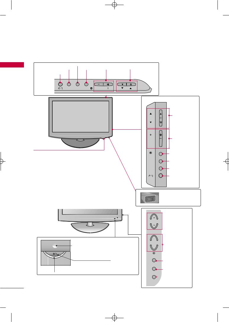
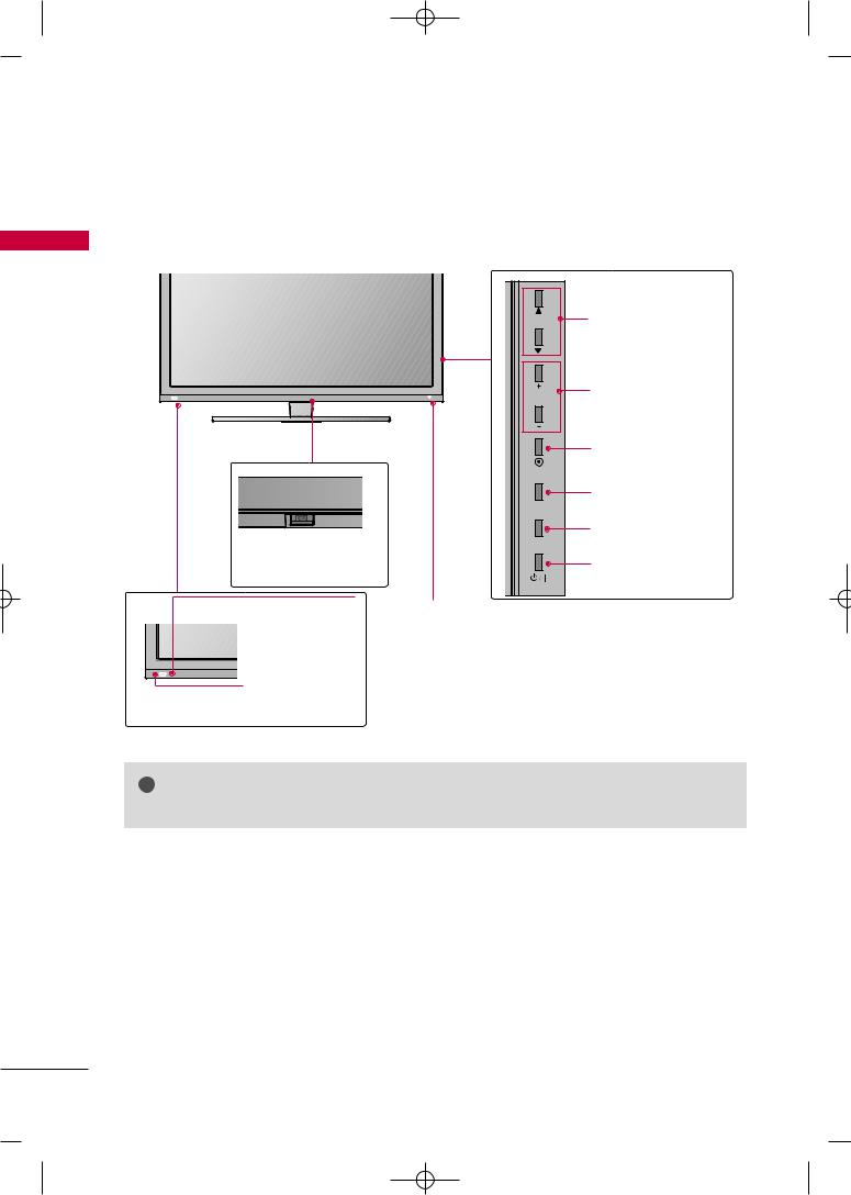
FRONT PANEL INFORMATION
■ Image shown may differ from your TV.
<![endif]>PREPARATION
For 19/22/26/32/37/42LH20R, 32/37/42/47LH30FR
19/22/26LH20R |
MENU Button |
|
|
|
INPUT Button |
|
|
CHANNEL |
|
ENTER |
|
VOLUME |
||
POWER Button |
Button |
|
(-, +) Buttons |
(E,D) Buttons |
INPUT |
MENU ENTER |
VOL |
CH |
|
Remote Control Sensor,
Power/Standby Indicator
Illuminates red in standby mode.
Illuminates blue when the TV is switched on.
(Can be adjusted Power Indicator in the O TION menu. G p.96)
For 32/42LF20FR
32/37/42LH20R,32/37/42/47LH30FR |
||
CH |
CHANNEL |
|
(D,E) Buttons |
||
|
||
VOL |
VOLUME (+, -) |
|
|
Buttons |
|
ENTER |
Button |
|
|
||
MENU |
Button |
|
INPUT |
Button |
|
|
Button |
|
ON OFF |
AC power control switch |
|
(Except 19/22LH20R) |
Power/Standby Indicator
Illuminates red in standby mode.
Illuminates blue when the TV is switched on.
Remote Control Sensor
POWER Button
 CHANNEL
Buttons
+
VOL  VOLUME
-Buttons
ENTER
ENTER Button
MENU
MENU Button
INPUT
 INPUT Button
10
MFL58486305-Edit1-en 10/21/09 11:07 AM Page 11
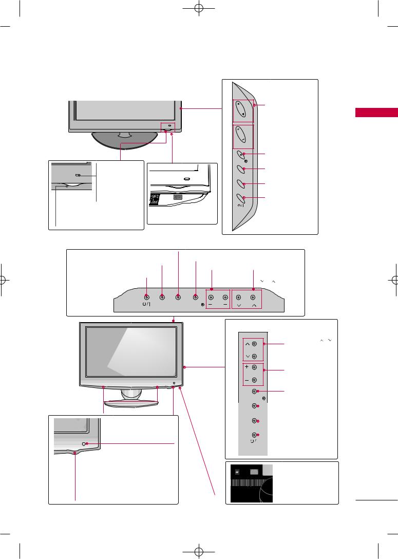
■ Image shown may differ from your TV.
For 42/47/55LH50YR
CHANNEL
CH
 VOLUME
Buttons
VOL
Remote Control
Sensor
Intelligent Sensor
according to the surrounding conditions.
Power/Standby Indicator
Illuminates red in standby mode. Illuminates blue when the TV is switched on.
|
ENTER Button |
|
ENTER |
|
MENU Button |
|
MENU |
|
INPUT Button |
|
INPUT |
OFF ON |
POWER Button |
AC power control |
|
switch |
|
For 19LU50R, 22LU50FR, 26LU50FR
19LU50R, 22LU50FR |
MENU Button |
|
|
|
ENTER Button |
|
|
||
INPUT Button |
|
|
||
|
VOLUME |
CHANNEL |
||
|
|
|||
POWER Button |
|
(-, +) Buttons ( , |
) Buttons |
|
INPUT |
MENU ENTER |
VOL |
CH |
|
|
|
26LU50FR |
|
|
|
|
|
|
CHANNEL ( , ) |
|
|
|
CH |
Buttons |
|
|
|
VOL |
VOLUME (+, -) |
|
|
|
Buttons |
|
|
|
|
|
|
|
ENTER Button |
|
ENTER |
SPEAKER |
MENU Button |
MENU |
|
|
Button |
|
Button |
Remote Control Sensor |
|
Power/Standby Indicator |
|
Illuminates red in standby mode. |
control |
|
Illuminates white when the TV is switched on.
<![endif]>PREPARATION
11
MFL58486305-Edit1-en 10/21/09 11:07 AM Page 12
PREPARATION
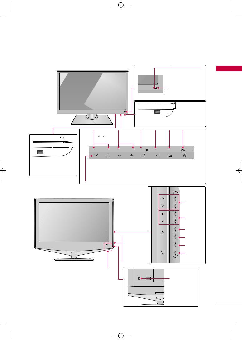
■ Image shown may differ from your TV.
For 32/42/47LH70YR
<![if ! IE]><![endif]>PREPARATION
Remote Control Sensor,
Intelligent Sensor
Adjusts picture according to the surrounding conditions.
Moving LED
POWER Button (Touch Sensor) ,
Power/Standby Indicator
Illuminates red in standby mode.
Illuminates white when the TV is switched on.
For 42/47LH90QR
SPEAKER
Remote Control Sensor,
Intelligent Sensor
Adjusts picture according to the surrounding conditions
Power/Standby Indicator
Illuminates red in standby mode.
Illuminates white when the TV is switched on.
(Can be adjusted using the P o w e r Indicator in the OPTION menu. G p.96)
CH
CHANNEL Buttons
VOL
VOLUME
Buttons
 ENTER Button
ENTER
MENU Button
MENU
INPUT Button
INPUT
 CAUTION
G When the TV cannot be turned on with the remote control, press the AC power control switch button on the TV.(The remote control will not work when the AC power control switch is switched off.)
12
MFL58486305-Edit1-en 10/21/09 11:07 AM Page 13
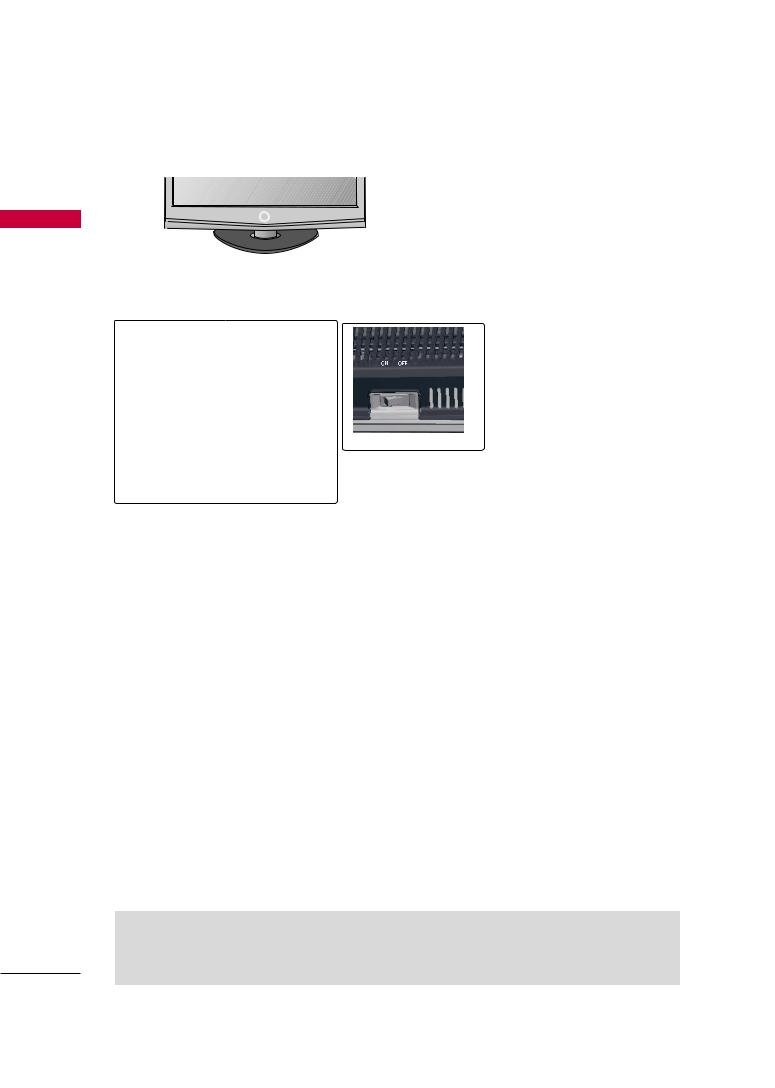
■ Image shown may differ from your TV.
32/42/47/55SL80YR |
|
|
Remote Control Sensor |
<![if ! IE]> <![endif]>PREPARATION |
|
Intelligent Sensor |
||
|
||
Adjusts picture |
|
|
according to the sur- |
|
|
rounding conditions |
|
CHANNEL |
VOLUME |
ENTER |
MENU |
INPUT |
POWER |
( , ) |
(-, +) |
Button |
Button |
Button |
Button |
Buttons |
Buttons |
|
|
|
|
ON  OFF
OFF
AC power control switch (For 32SL80YR)
Power/Standby Indicator
Illuminates red in standby mode.
Illuminates blue when the TV is switched on (Can be adjusted using the Power Indicator in the OPTION menu. G p.96).
22LU40R |
|
|
|
|
<![if ! IE]> <![endif]>CH |
CHANNEL |
|
|
|
||
|
<![if ! IE]> <![endif]>VOL |
VOLUME |
|
|
Buttons |
||
|
|
||
|
<![if ! IE]> <![endif]>ENTER |
ENTER |
|
|
Button |
||
Power/Standby |
<![if ! IE]> <![endif]>MENU |
MENU |
|
Button |
|||
|
|||
Indicator |
<![if ! IE]> <![endif]>INPUT |
||
|
|||
• illuminates red in |
INPUT |
||
standby mode. |
|
Button |
|
• The LED is off |
|
||
|
POWER |
||
while the TV |
|
||
|
Button |
||
remains on. |
|
||
Remote Control Sensor |
|
|
|
|
|
|
|
|
|
|
13
MFL58486305-Edit1-en 10/21/09 11:07 AM Page 14
PREPARATION
■ Image shown may differ from your TV.
For 42/47SL90QR |
|
|
|
|
| <![if ! IE]> <![endif]>PREPARATION |
|
CH |
CHANNEL (D,E) |
|
|
|
|
Buttons |
|
|
|
VOL |
VOLUME (+, -) |
|
|
|
Buttons |
||
|
|
|
||
|
|
|
ENTER Button |
|
|
|
ENTER |
|
|
|
|
|
MENU Button |
|
|
|
MENU |
|
|
OFF |
ON |
|
INPUT Button |
|
|
|
|
||
AC power |
|
INPUT |
|
|
|
|
|
||
control switch |
|
POWER Button |
||
Remote Control Sensor |
Power/Standby Indicator |
|
||
Intelligent Sensor |
Illuminates red in standby mode. |
|||
Illuminates white when the TV is switched on (Can be |
||||
|
|
|||
Adjusts picture |
adjusted using the Power Indicator in the OPTION |
|||
according to the |
menu. G p.96). |
|
||
surrounding condi- |
|
|
||
tions |
|
|
|
|
! NOTE |
G Do not step on the glass stand or subject it to any impact.It may break, causing possible |
|
injury from fragments of glass, or the TV may fall. |
G Do not drag the TV. The floor or the product may be damaged.
14
MFL58486305-Edit1-en 10/21/09 11:07 AM Page 15
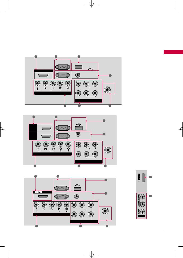
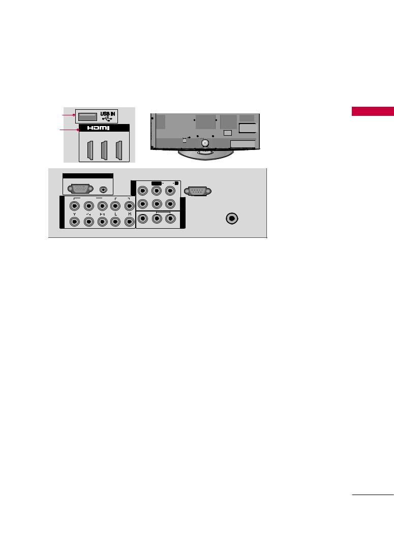
BACK PANEL INFORMATION
■ Image shown may differ from your TV.
For 19/22LH20R, 22LU40R
2 |
|
3 |
|
8 |
|
|
|
|
|
RS- |
IN |
|
|
|
|
|
|
(CONTROL) |
|
USB IN |
|
|
|
|
|
|
|
|
|
|
|
|
|
|
|
|
SERVICE ONLY |
|
|
HDMI/DVI IN |
RGB IN (PC) |
|
AUDIO IN |
|
|
||
|
|
|
|
|
|
4 |
|
|
|
|
|
|
(RGB/DVI) |
|
|
|
|
|
|
|
|
IN |
ANTENNA IN |
|
|
|
|
VIDEO |
L(MONO) AUDIO |
|
|
|
|
|
|
R |
|
||
|
VIDEO |
AUDIO |
|
|
|
|
|
|
COMPONENT IN |
|
|
|
OUT |
|
|
|
|
|
|
|
|
|
|
|
|
|
|
|
VARIABLE AUDIO OUT |
|
|
|
|
|
|
|
AV |
|
|
|
|
|
5 |
6 |
|
|
7 |
For 26/32/37/42LH20R |
|
|
|
|
|
||
2 |
|
3 |
|
|
|
|
|
|
|
RS-232C IN |
USB IN |
|
8 |
||
|
|
SERVICE ONLY |
|
||||
|
|
|
|
||||
|
|
(CONTROL) |
|
|
|
|
|
HDMI |
2 |
|
|
|
|
|
|
HDMI |
|
RGB IN (PC) |
|
AUDIO IN |
|
4 |
|
1 |
|
|
|
(RGB/DVI) |
|
||
|
|
|
|
|
|||
/DVI IN |
|
|
|
|
|
|
|
|
|
|
|
VIDEO |
L(MONO) AUDIO |
IN |
|
|
|
|
|
R |
|
||
|
VIDEO |
AUDIO |
|
|
|
|
|
|
COMPONENT IN |
|
|
|
OUT |
ANTENNA |
|
|
|
|
|
|
|
||
|
|
|
|
|
|
IN |
|
|
|
|
|
|
VARIABLE AUDIO OUT |
|
|
|
|
|
|
|
AV |
|
|
5 |
|
|
|
6 |
|
|
|
For 32/42LF20FR |
|
|
|
|
|
|
|
2 |
|
3 |
|
|
|
|
|
|
|
RS-232C IN |
USB IN |
|
|
8 |
|
|
|
SERVICE ONLY |
|
|
|||
|
|
(CONTROL) |
|
|
|
|
|
|
/DVI IN |
|
|
|
|
|
4 |
|
|
|
|
AUDIO IN |
|
||
|
|
|
|
|
|
||
|
|
|
|
(RGB/DVI) |
|
|
|
|
|
|
|
|
IN 1 |
|
|
|
VIDEO |
AUDIO |
VIDEO L(MONO) AUDIO R |
|
|
||
|
|
|
|
|
|||
|
COMPONENT IN |
|
|
OUT |
ANTENNA |
||
|
|
|
|
|
|
|
|
|
|
|
|
VARIABLE AUDIO OUT |
|
IN |
|
|
|
|
|
|
AV |
|
|
5 |
|
|
|
6 |
|
7 |
|
<![endif]>PREPARATION
| <![if ! IE]> <![endif]>2 |
2 |
|
| <![if ! IE]> <![endif]>IN |
||
|
6
AV IN2
15

MFL58486305-Edit1-en 10/21/09 11:07 AM Page 16
PREPARATION
■ Image shown may differ from your TV.
For 32/37/42/47LH30FR
| <![if ! IE]> <![endif]>PREPARATION |
2 |
|
3 |
1 |
|
|
|
|
|
|
|
|
|||
|
|
|
|
|
|
|
|
|
|
|
RS-232C IN |
|
|
|
|
|
|
|
(CONTROL) |
|
|
|
|
|
|
2 |
|
|
|
|
|
|
|
|
RGB IN (PC) |
AUDIO IN |
|
|
|
|
|
|
(RGB/DVI) |
|
|
|
|
|
/DVI IN |
1 |
|
|
|
4 |
|
|
|
|
|
VIDEO |
L(MONO) |
AUDIO |
R |
|
|
|
|
|
|
|
<![if ! IE]> <![endif]>1 IN AV |
VIDEO |
AUDIO |
|
|
COMPONENT IN |
|
|
|
|
VARIABLE AUDIO OUT |
|
ANTENNA |
|
AV OUT |
|
IN |
5 |
|
6 |
7 |
For 19LU50R, 22LU50FR
|
2 |
3 |
VID 8 |
L(MONO) AUDIO R |
|
|
|
|
RS-232C IN |
USB IN |
|
|
|
|
|
|
ONLY |
|
|
|
|
|
(CONTROL) |
|
|
|
|
|
|
|
|
|
|
|
HDMI/DVI IN |
|
|
|
|
|
|
2 |
|
RGB IN (PC) |
VARIABLE AUDIO OUT |
|
|
|
|
|
|
AUDIO IN |
|
|
|
1(DVI) |
|
|
|
|
4 |
|
|
|
|
|
(RGB/DVI) |
|
|
|
|
|
EO |
L(MONO) AUDIO |
|
<![if ! IE]> <![endif]>IN AV |
|
|
|
|
|
|
|
VIDEO |
|
AUDIO |
|
|
|
|
COMPONENT IN |
|
|
|
|
||
|
|
|
|
VARIABLE AUDIO |
T |
ANTENNA |
|
|
|
|
AV OUT |
|
|
|
|
|
|
|
IN |
|
|
|
5 |
|
|
6 |
7 |
For 26LU50FR |
2 |
3 |
8 |
|
|
|
|
|
RS-232C IN |
USB IN |
|
|
|
|
|
SERVICE ONLY |
|
|
||
|
|
(CONTROL) |
|
|
||
|
|
|
|
|
|
|
HDMI/DVI IN |
|
|
|
|
|
|
2 |
|
RGB IN (PC) |
|
AUDIO IN |
|
|
|
|
|
|
|
||
|
|
|
|
|
|
|
1(DVI) |
|
|
|
(RGB/DVI) |
|
4 |
|
|
|
DEO |
L(MONO) AUDIO |
R |
<![if ! IE]> <![endif]>1 IN AV |
|
|
|
|
|
|
|
VIDEO |
|
AUDIO |
|
|
|
|
COMPONENT IN |
|
|
|
|
||
|
|
|
|
VARIABLE AUDIO OUT |
ANTENNA |
|
|
|
|
|
AV OUT |
|
|
|
|
|
|
|
IN |
|
|
|
5 |
|
|
6 |
7 |
8
| <![if ! IE]> <![endif]>3 |
2 |
|
| <![if ! IE]> <![endif]>IN |
||
|
6
AV IN2
| <![if ! IE]> <![endif]>3 |
2 |
| <![if ! IE]> <![endif]>IN |
|
6
AV IN2
16
MFL58486305-Edit1-en 10/21/09 11:07 AM Page 17
■ Image shown may differ from your TV.
For 32/42/47LH70YR
|
8 |
|
|
|
|
|
|
|
|
3 |
2 |
1(DVI) |
|
|
|
|
|
|
|
4 |
|
6 |
1 |
|
|
|
|
|
|
||
|
|
RGB IN |
|
|
|
|
|
|
|
|
(RGB/DVI) |
<![if ! IE]> <![endif]>AV |
VIDEO |
L/MONO AUDIO R |
RS-232C IN |
|
|
|
(CONTROL) |
||||
|
|
|
|
|
|
||
|
|
|
|
<![if ! IE]> <![endif]>2 IN |
|
|
|
|
<![if ! IE]> <![endif]>IN COMPONENT |
VIDEO |
|
AUDIO |
|
|
<![if ! IE]> <![endif]>OUT AV 1 IN AV |
5 |
2 |
|
|
|
|
||
|
|
|
|
|
|||
|
1 |
|
|
|
VARIABLE AUDIO OUT |
||
|
|
|
|
|
|||
For 42/47/55LH50YR, 42/47LH90QR |
|||||||
2
RS-232C IN (CONTROL)


 /DVI IN
2 |
AUDIO IN |
|
|
RGB IN (PC) |
(RGB/DVI) |
|
|
|
1(DVI) |
|
|
|
|
|
|
|
VIDEO L(MONO) AUDIO |
R |
<![if ! IE]> <![endif]>AV |
|
2 |
|
|
|
|
|
|
|
|
<![if ! IE]> <![endif]>1 IN |
|
|
|
|
|
|
|
|
1 |
|
|
|
7 |
|
|
|
|
|
|
|
VIDEO |
AUDIO |
VARIABLE AUDIO OUT |
ANTENNA |
|
|
AV OUT |
|
|||
5 |
COMPONENT IN |
|
IN |
||
For 32/42/47/55SL80YR
|
2 |
|
|
|
|
|
|
|
1 |
|
|
|
|
IN |
|
|
RGB IN (PC) |
AUDIO IN |
|
|
/DVI IN |
|
(RGB/DVI) |
4 |
|||
|
|
|
|
|
||
|
|
|
|
|
|
|
2 |
|
1 |
|
|
|
|
|
|
|
|
AV IN 1 |
|
|
2 |
|
|
|
|
|
|
|
|
L |
R |
VIDEO |
L(MONO) AUDIO R |
|
1 |
|
|
|
|
|
7 |
|
|
|
|
|
|
|
VIDEO |
|
AUDIO |
|
VARIABLE AUDIO OUT |
ANTENNA |
|
COMPONENT IN |
|
|
AV OUT |
IN |
||
|
|
|
||||
|
5 |
|
|
|
|
|
<![endif]>PREPARATION
8
| <![if ! IE]> <![endif]>3 |
2 |
|
| <![if ! IE]> <![endif]>IN |
||
|
6
AV IN2
| <![if ! IE]> <![endif]>USB IN |
8 |
|
| <![if ! IE]> <![endif]>IN 3 |
|
|
|
2 |
|
| <![if ! IE]> <![endif]>R |
6 |
|
| <![if ! IE]> <![endif]>L/MONO AUDIO |
||
|
||
| <![if ! IE]> <![endif]>VIDEO |
|
AV IN 2
17
MFL58486305-Edit1-en 10/21/09 11:07 AM Page 18
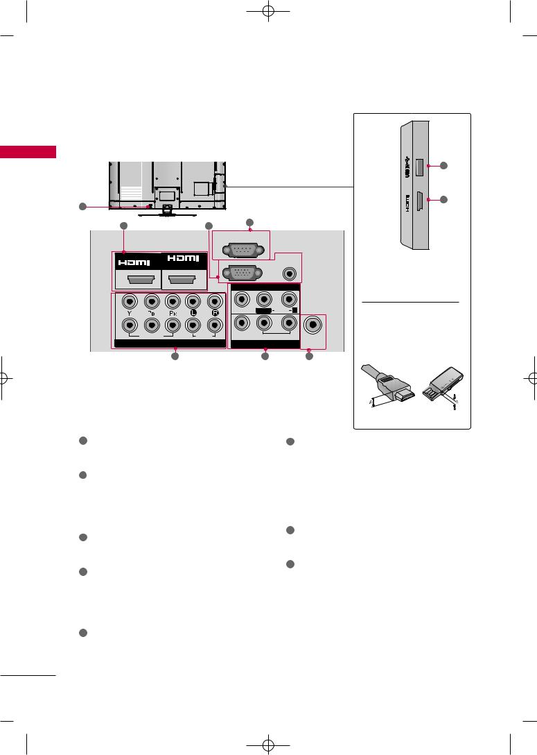
PREPARATION
<![endif]>PREPARATION
1
8
<![if ! IE]><![endif]>IN 3
2
1
For operation with AC power.
Caution: Never attempt to operate the TV on DC power.
2HDMI/DVI IN, HDMI IN
Digital Connection.
Supports HD video and Digital audio. Doesn’t support 480i/576i.
Accepts DVI video using an adapter or HDMI to DVI cable (not included).
3
(Except 32/42/47/55SL80YR) Used by third party devices.
RGB IN (PC)
Analog PC Connection. Uses a D-sub 15 pin cable (VGA cable).
AUDIO IN (RGB/DVI)
1/8" (0.32 cm) headphone jack for analog PC audio input.
5
Analog Connection. Supports HD.
Uses a red, green, and blue cable for video & red and white for audio.
 CAUTION
For HDMI IN 3 and USB IN
G For an optimal connection, HDMI cables and USB devices should have bezels less than 0.39 inches (10 mm) thick.
*A  0.39 inches (10 mm)
6
Analog composite connection. Supports standard definition video only (480i).
AV Output
Connect second TV or monitor to the AV OUT socket on the TV.
Variable Audio Output
Connect an external amplifier or add a subwoofer to your surround sound system.
ANTENNA IN
Connect over-the air signals to this jack.
Connect cable signals to this jack.
8USB IN
(For 32/37/42/47LH30FR, 42/47/55LH50YR, 32/42/47LH70YR, 42/47LH90QR, 32/42/47/55SL80YR)
Used for viewing photos/movies and listening to MP3.
USB IN SERVICE ONLY
(For 19/22/26/32/37/42LH20R, 32/42LF20FR, 19LU50R, 22/26LU50FR, 22LU40R)
Used for software updates.
18
MFL58486305-Edit1-en 10/21/09 11:07 AM Page 19
STAND INSTRUCTION
■ Image shown may differ from your TV.
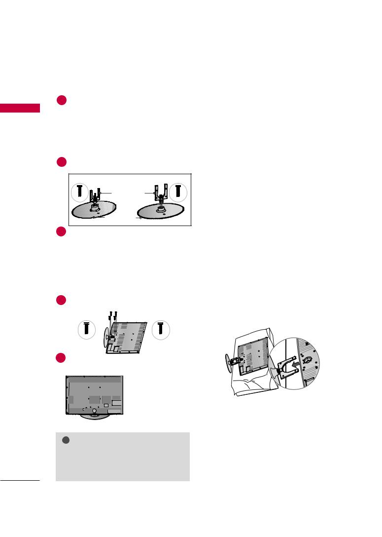
For 19/22LH20R
INSTALLATION
1 |
2 |
cushioned surface to protect the screen from damage.
DETACHMENT |
PROTECTION COVER |
|
1 |
place the TV screen side down on a |
4 |
|
surface to protect the screen from |
|
|
damage. |
|
|
|
PROTECTION COVER |
2 |
5 |
securely using the holes in the |
|
|
3
<![endif]>PREPARATION
19
MFL58486305-Edit1-en 10/21/09 11:07 AM Page 20
PREPARATION
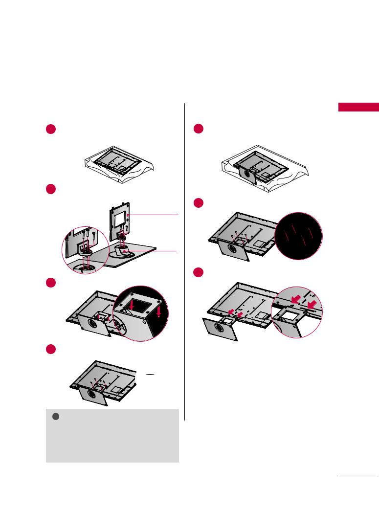
For 26/32/37/42LH20R, 32/37/42/47LH30FR, 42/47LH50YR, 42/47LH90QR
<![endif]>PREPARATION
INSTALLATION |
|
DETACHMENT |
||
1 |
the TV screen side down on a |
1 |
place the TV screen side down on a |
|
surface to protect the screen from |
||||
|
to protect the screen from |
|
||
|
|
damage. |
||
damage. |
|
|
||
|
|
|
||
2Assemble the TV as shown.
3Fix the 4 bolts securely using the holes in the back of the TV.
! NOTE
GWhen assembling the desk type stand, make sure the bolt is fully tightened (If not tightened fully, the TV can tilt forward after the product installation). Do not over tighten.
2
3
PROTECTION COVER
For 26/32/37/42LH20R, 32/37/42/47LH30FR, 42/47/55LH50YR
After removing the stand, install the included protection cover over the hole for the stand.
Press the PROTECTION COVER into the TV until you hear it click.
For 42/47LH90QR
Insert the PROTECTION COVER into the TV. After removing the protection paper from the protection cover, adhere it to the TV as shown.
20
MFL58486305-Edit1-en 10/21/09 11:07 AM Page 21
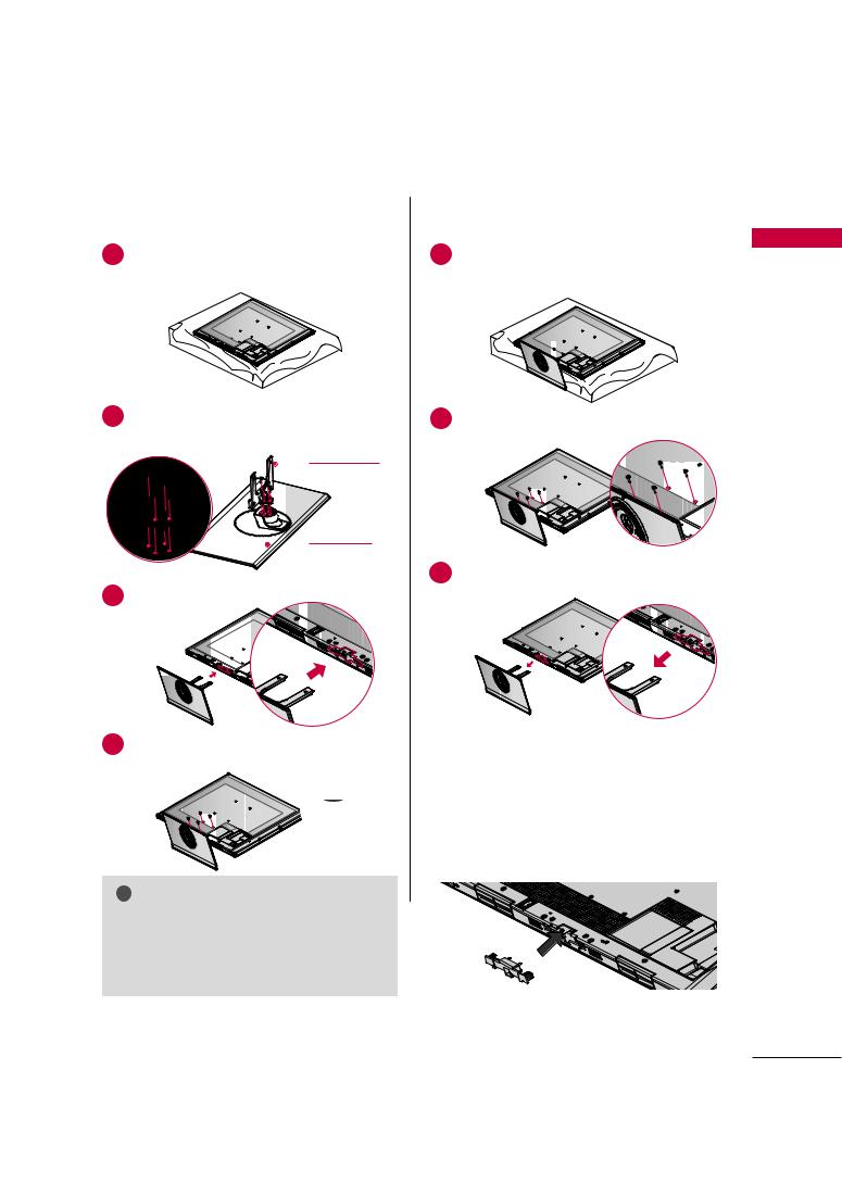
For 32/42LF20FR
INSTALLATION
1 Carefully place TV screen side down on a cushioned surface to protect the screen from damage.
2Assemble the STAND BODY to the STAND BASE with the included screws.
DETACHMENT
1place the TV
surface to
damage.
2
3Assemble the
4 |
Fix the 4 bolts |
securely using the holes in the |
back of the TV. |
|
PROTECTION COVER
After removing the stand, install the included protection cover over the hole for the stand.
Press the PROTECTION COVER into the TV until you hear it click.
<![endif]>PREPARATION
21
MFL58486305-Edit1-en 10/21/09 11:07 AM Page 22
PREPARATION
For 19LU50R, 22/26LU50FR
INSTALLATION
1 |
|
down on a |
|
|
screen from |
| <![if ! IE]> <![endif]>PREPARATION |
damage. |
|
|
|
|
2 |
Fix the bolts securely using the holes. |
|
|
19LU50R, 22LU50FR |
|
|
19" |
22" |
26LU50FR
DETACHMENT
1place the TV screen side down on a
surface to protect the screen from
damage.
2 |
bolts and then detach the stand |
19LU50R, 22LU50FR
26"
26LU50FR
3
And detach the COVER BASE from the TV.
COVER BASE
! NOTE
GWhen assembling the desk type stand, make sure the bolt is fully tightened (If not tightened fully, the TV can tilt forward after the product installation). Do not over tighten.
19LU50R, |
26LU50FR |
4
STAND BODY
22
MFL58486305-Edit1-en 10/21/09 11:07 AM Page 23
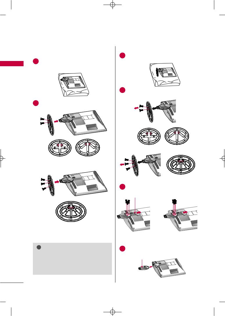
For 42/47SL90QR
■ Image shown may differ from your TV. |
|
|
|
INSTALLATION |
|
DETACHMENT |
|
1 |
side down on a |
1 |
place the TV screen side down on a |
|
the screen from |
|
surface to protect the screen from |
damage. |
|
|
damage. |
2Assemble the parts of the Stand Body with the Stand Base of the TV.
2
20 mm
STAND BODY
STAND BASE
3
3Assemble the TV as shown.
4 |
the |
16 mm
! NOTE
GWhen assembling the desk type stand, make sure the screws are fully tightened (If not tightened fully, the TV can tilt forward after the product installation). Do not over tighten.
<![endif]>PREPARATION
23
MFL58486305-Edit1-en 10/21/09 11:07 AM Page 24
PREPARATION
For 32/42/47LH70YR
■ Image shown may differ from your TV.
INSTALLATION
1
<![if ! IE]><![endif]>PREPARATION
2
-
to the STAND
DETACHMENT
1 |
shown. |
|
2 |
32LH70YR, 42LH70YR |
47LH70YR |
|
damage. |
Stand Body |
|
M4x20 |
M4x16 |
Stand Base |
|
3
place the TV screen side down on a surface to protect the screen from
3
4 |
the |
32LH70YR
4
M4x20
5
(For 42/47LH70YR)
PROTECTION COVER
from the TV as shown.
STAND EAR COVER
! NOTE
G When assembling the desk type stand, make sure the bolt is fully tightened (If not tightened fully, the TV can tilt forward after the product installation). Do not over tighten.
24
MFL58486305-Edit1-en 10/21/09 11:07 AM Page 25
For 32/42/47/55SL80YR
■ Image shown may differ from your TV.
INSTALLATION (Except 55SL80YR)
1 side down on a the screen from
damage.
2Assemble the parts of the Stand Body with the Stand Base of the TV.
STAND BODY
STAND BASE
3Assemble the TV as shown.
4 |
the |
! NOTE
GWhen assembling the desk type stand, make sure the screws are fully tightened (If not tightened fully, the TV can tilt forward after the product installation). Do not over tighten.
DETACHMENT
1place the TV screen side down on a
surface to protect the screen from
damage.
2
3
PROTECTION COVER
After removing the stand, install the included protection cover over the hole for the stand.
Press the PROTECTION COVER into the TV until you hear it click.
<![endif]>PREPARATION
25
MFL58486305-Edit1-en 10/21/09 11:08 AM Page 26
PREPARATION
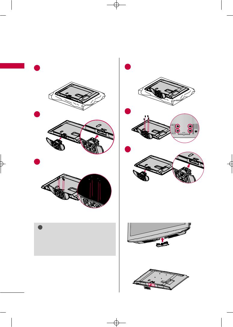
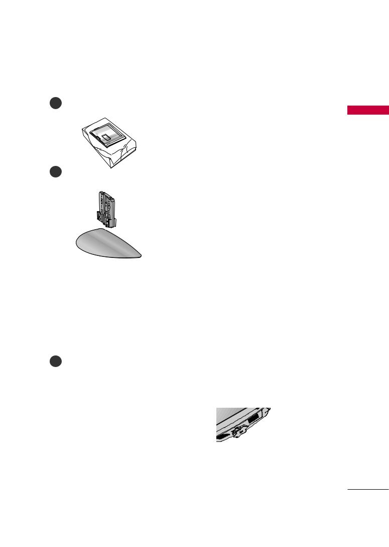
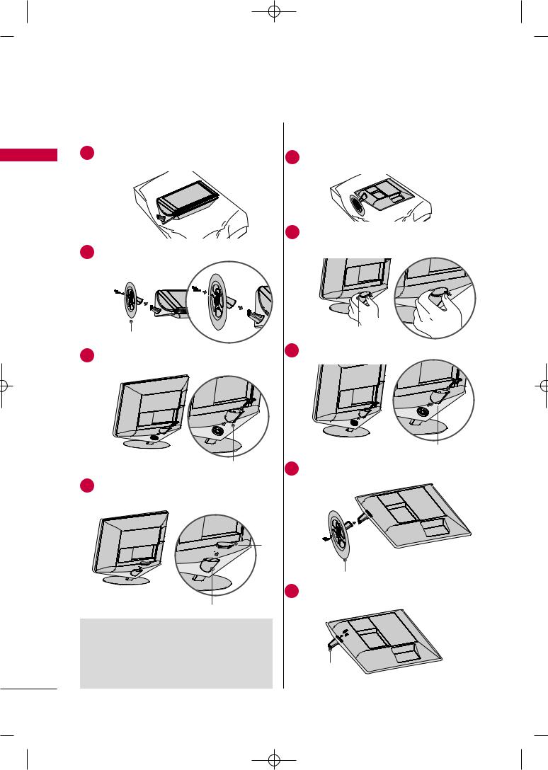
For 22LU40R
■ Image shown may differ from your TV.
INSTALLATION
1 |
place the TV screen side down on a cush- |
|
<![endif]>PREPARATION
2Fix the 3 Bolts securely using the holes in the Cover Base.
Cover Base
3Assemble the parts with the TV.
DETACHMENT
1Carefully place the TV screen side down on a cushioned surface to protect the screen from damage.
2Detach the Cap from TV.
Press in the direction of the arrow to detach the cap.
3Loose the Screws and Rear Body from TV.
4 |
Loose the |
and |
Base from TV |
|
4 |
Assemble the |
and |
Rear Body |
|
|
|
|
Cap
Stand Rear Body
 NOTE
NOTE
GWhen assembling the desk type stand, make sure the bolt is fully tightened (If not tightened fully, the TV can tilt forward after the product installation). Do not over tighten.
Cover Base
5Loose the Screws and Body from TV.
Stand Body
26
MFL58486305-Edit1-en 10/21/09 11:08 AM Page 27
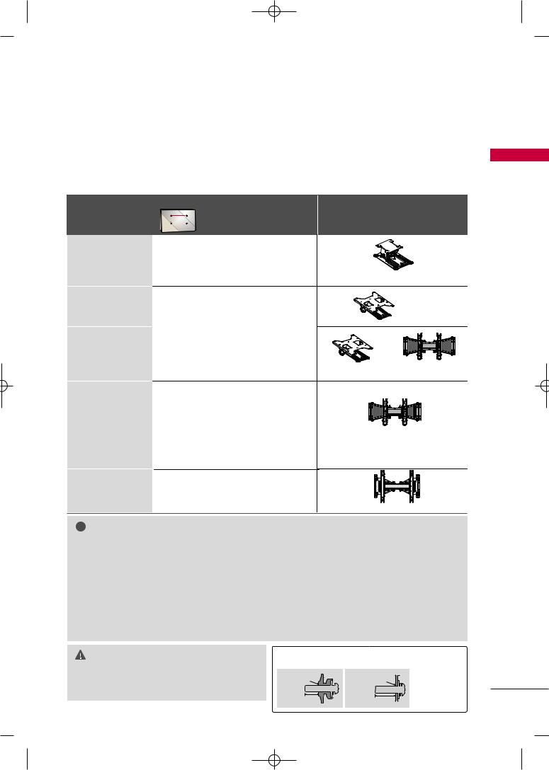
VESA WALL MOUNTING
Install your wall mount on a solid wall perpendicular to the floor. When attaching to other building materials, please contact your nearest installer.
If installed on a ceiling or slanted wall, it may fall and result in severe personal injury. We recommend that you use an LG brand wall mount when mounting the TV to a wall. LG recommends that wall mounting be performed by a qualified professional installer.
For 32/42/47LH70YR: First you connect the USB extension cable to the USB IN terminal, and then hang it on the wall.
|
VESA (A * B) |
|
|
|
Model |
A |
Standard Screw |
Quantity |
|
|
B |
|
|
|
19/22LH20R, |
|
|
|
|
19LU50R, 22LU50FR, |
100 * 100 |
M4 |
4 |
|
22LU40R |
|
|
|
|
26LH20R, 26LU50FR |
|
|
|
|
32LH20R, 32LF20FR, |
200 * 100 |
M4 |
4 |
|
32LH30FR, |
|
|
|
|
32LH70YR, |
|
|
|
|
32SL80YR |
|
|
|
|
37/42LH20R, |
|
|
|
|
42LF20FR, |
|
|
|
|
37/42/47LH30FR, |
|
|
|
|
42/47LH50YR, |
200 * 200 |
M6 |
4 |
|
42/47LH70YR, |
||||
|
|
|
||
42/47LH90QR |
|
|
|
|
42/47SL80YR, |
|
|
|
|
42/47SL90QR |
|
|
|
|
55LH50YR, |
400 * 400 |
M6 |
4 |
|
55SL80YR |
||||
|
|
|
Wall Mount Bracket (sold separately)
RW120
RW230
RW230 AW-47LG30M
AW-47LG30M
AW-55LH40M
! NOTE
G Screw length needed depends on the wall mount used. For further information, refer to the instructions included with the mount.
GStandard dimensions for wall mount kits are shown in the table.
GWhen purchasing our wall mount kit, a detailed installation manual and all parts necessary for assembly are provided.
GDo not use screws longer then the standard dimension, as they may cause damage to the inside to the TV.
G For wall mounts that do not comply with the VESA standard screw specifications, the length of the screws may differ depending on their specifications.
GDo not use screws that do not comply with the VESA standard screw specifications.
Do not fasten the screws too tightly, this may damage the TV or cause the TV to a fall, leading to personal injury. LG is not liable for these kinds of accidents.
GLG is not liable for TV damage or personal injury when a non-VESA or non specified wall mount is used or the consumer fails to follow the TV installation instructions.
CAUTION |
(For 42/47LH70YR, 42/47SL80YR, 42/47SL90QR) |
||
Use screws 12mm(±0.5) long on the TV assembly side (sold separately). |
|||
|
|||
G Do not install your Wall Mount Bracket while your |
Withguidespacer |
|
|
TV is turned on. It may result in personal injury due |
Without guide spacer |
||
to electric shock. |
|
|
|
<![endif]>PREPARATION
12mm |
12mm |
27
MFL58486305-Edit1-en 10/21/09 11:08 AM Page 28
PREPARATION
CABLE ARRANGEMENT
■ Image shown may differ from your TV.
For 19/22LH20R
| <![if ! IE]> <![endif]>PREPARATION |
1 |
|
|
|
EXTERNAL EQUIPMENT SETUP section. |
2 Install the CABLE MANAGEMENT CLIP as shown.
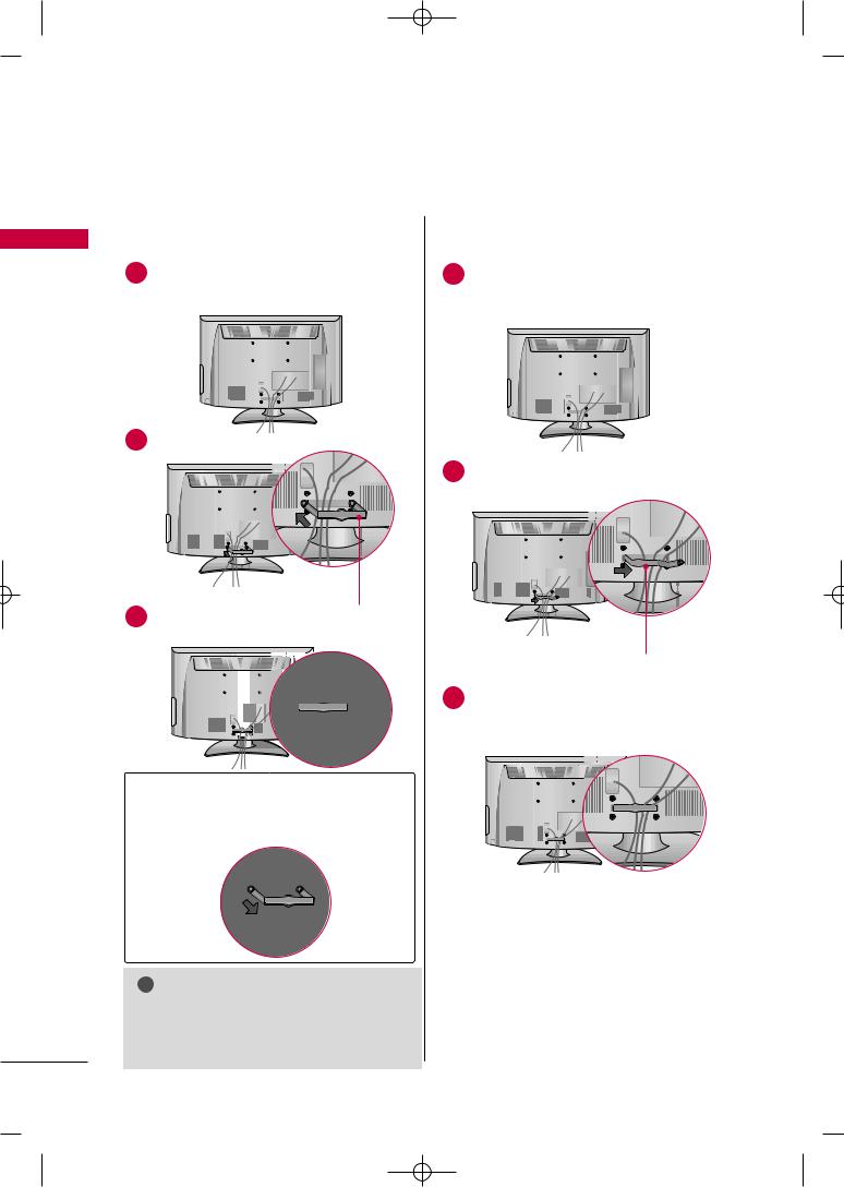
For 26/32/37/42LH20R, 32/42LF20FR, 32/37/42/47LH30FR, 42/47/55LH50YR, 42/47LH90QR
1Connect the cables as necessary.
To connect additional equipment, see the
EXTERNAL EQUIPMENT SETUP section.
2 |
|
CABLE MANAGEMENT CLIP |
3 |
MANAGE- |
Install the CABLE MANAGEMENT CLIP as shown.
3
How to remove the CABLE
MANAGEMENT CLIP
G Hold the CABLE MANAGEMENT CLIP with both hands and pull it backward.
! NOTE
G Do not hold the CABLE MANAGEMENT CLIP when moving the TV.
-If the TV is dropped, you may be injured or the product may be broken.
CABLE MANAGEMENT CLIP
MANAGE-
28
 Loading...