


42PG10R
Table of contents
 Loading...
LG 42PG10R, 3230R, 3750FR, 32PC5RA, 42PG20R Manual
...
LCD TV
PLASMA TV
OWNER’S MANUAL
LCD TV MODELS
22/26LG1
***
32/37LG1
***
42/47LG1
***
22/26LG3
***
32/37LG3
***
42/47LG3
***
32LG5
***
37/42LG5
***
47/52LG5
***
PLASMA TV MODELS
32PC5***
42PG1
***
50PG1
***
42PG2
***
50PG2
***
Please read this manual carefully before operating your set.
Retain it for future reference.
Record model number and serial number of the set.
Refer to the label on the back cover and quote this
information.
To your dealer when requiring service.
ENGLISH

Ferrite core can be used to reduce the electromagnetic
wave when connecting the power cord.
The closer the location of the ferrite core to the power
plug, the better it is.
Use of ferrite core
(
This feature is not available for all models.
)
Install the power plug closely.
1
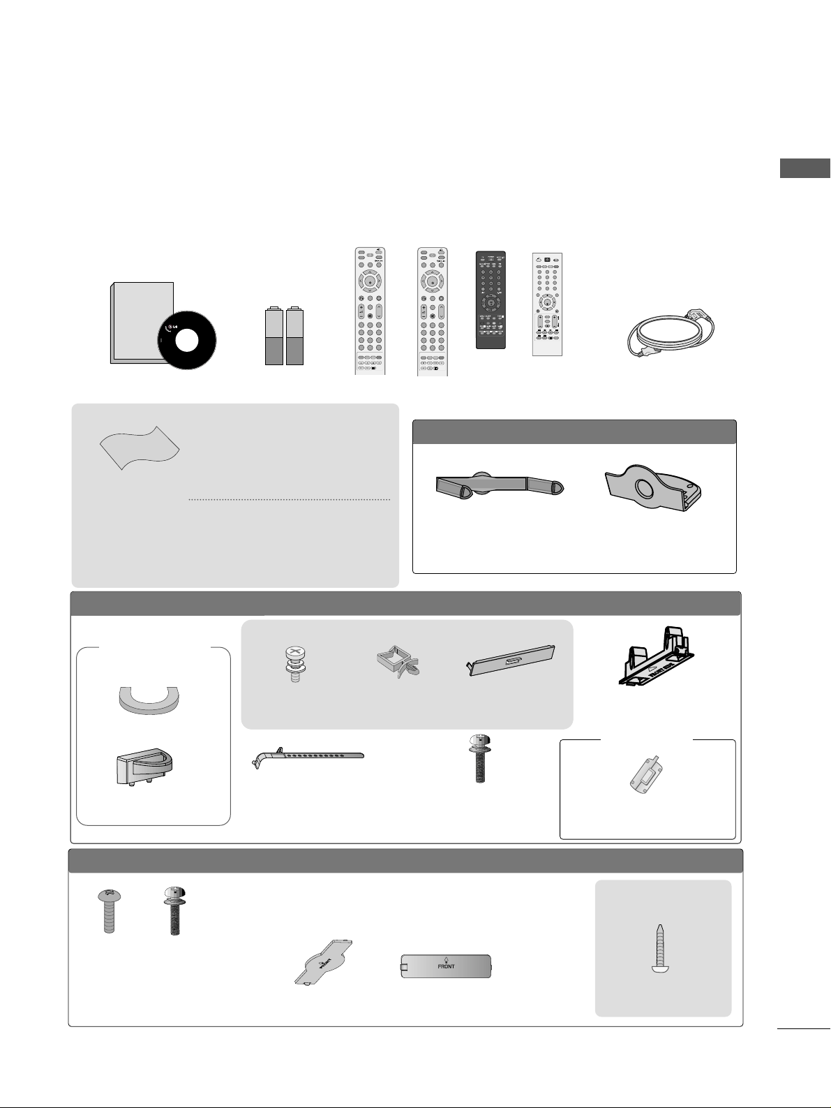
ACCESSORIES
Ensure that the following accessories are included with your TV. If an accessory is missing, please contact the
dealer where you purchased the product.
Owner's
Manual
Owner’s manual
Owner’s Manual Batteries Power Cord
Polishing Cloth
Polishing cloth for use
on the screen
This feature is not
available
for all models.
*
Lightly wipe any stains or
fingerprints on the surface
of the TV with the polishing
cloth.
Do not use excessive force.
This may cause scratching or
discolouration.
LLCCDD TTVV mmooddeellss
Bolts for stand assembly
(Refer to p.11)
(Only 32/37/42LG5
***
,
26/32/37/42LG1
***
,
26/32/37/42LG3
***
)
x 4 x 4
protection cover
PPLLAASSMMAA TTVV mmooddeellss
(
only
42/50PG1
***
)
Bolts for stand assembly
(Refer to P.12)
(42PG1
***
, 42PG2
***
:4EA
)
protection cover
(only 42/50PG2
***
)
Cable
Management Clip
(Only 26/32/42LG1
***
,
26/32/37/42LG3
***
,
32/37/
42L G5
***
)
Screw for stand fixing
(Refer to P. 12)
ACCESSORIES
or
MUTE
PIP
AV MODE
FAV
TV
INPUT
STB
POWER
Q. MENU
MENU
OK
123
456
78
0
9
LIST
Q.VIEW
DVD
TIME
SIZE
UPDATE
REVEAL
INDEX
HOLD TEXT
RETURN
P
MUTE
PIP
AV MODE
FAV
RATIO
INPUT
SOUND
POWER
Q. MENU
MENU
OK
123
456
78
0
9
LIST
Q.VIEW
PICTURE
TIME
SIZE
UPDATE
REVEAL
INDEX
HOLD TEXT
RETURN
P
RATIO
Remote Control
or or or
OOnnllyy 2222LLGG33
******
Cable Management Clip Protection Cover
Cable Holder
(42PG1
***
, 42PG2
***
:1EA
,
50PG1
***
, 50PG2
***
: 2EA
)
Only 32PC5
***
4-bolts for stand
assembly
Refer to p. 12
Holder
(Refer to p.16)
Cover
(Refer to p.19)
OK
MENU Q.MENU
AV MODE
123
456
789
0
Q.VIEW
LIST
INPUT
POWER
PRVOL
M
U
TE
FAV
*
RETURN
TE
XT
P
IP
?
i
P
A
G
E
This feature is not available
for all models.
Ferrite Core
Watching PIP(Picture-in-Picture).............................63
Picture Size (Aspect Ratio)Control.........................64
Preset Picture Settings
- Picture Mode-Preset............................................66
- Auto Colour Tone Control(Cool/Medium/Warm)
67
Manual Picture Adjustment
- Picture Mode-User Option................................68
- Colour Tone - User Option...............................69
-
Picture Improvement Technology
...................70
Advanced - Gamma......................................................71
Advanced - Film Mode ................................................72
Advanced - Black(Darkness) Level...........................73
Advanced - Eye Care ...................................................74
Picture Reset..................................................................75
Image Sticking Minimization(ISM) Method...........76
Power Saving Picture Mode .......................................77
Power Indicator..............................................................77
Factory Reset.................................................................78
Remote Control Key Functions..................................40
Turning on the TV....................................................... 48
Programme Selection ................................................. 48
Volume Adjustment......................................................48
Quick Menu .................................................................. 49
On Screen Menus Selection and Adjustment ......50
PICTURE CONTROL
WATCHING TV / PROGRAMME CONTROL
AACCCCEESSSSOORRIIEESS
.....................................................1
2
CONTENTS
CONTENTS
PREPARATION
Front Panel Controls................................................... 4
Back Panel Information .............................................. 7
Stand Installation........................................................11
Please set it up carefully so the product
does not fall over.
. . . . . . . . . . . . . . . . . . . . . . . . .13
Back Cover for Wire Arrangement......................... 14
Swivel Stand ............................................................... 17
Positioning your display............................................17
Location........................................................................17
Kensington Security System ...................................17
Desktop Pedestal Installation................................. 18
Wall Mount: Horizontal installation....................... 18
Not using the desk-type stand................................19
Antenna Connection................................................ 20
PREPARATION
EXTERNAL EQUIPMENT SETUP
HD Receiver Setup .......................................................21
DVD Setup .................................................................... 24
VCR Setup..................................................................... 27
Headphone SETUP ......................................................30
Other A/V Source Setup........................................... 31
External Stereo Setup..................................................32
AV Output Setup ........................................................ 32
PC Setup.........................................................................33
- Screen Setup for PC Mode ...............................36
Auto Programme Tuning ............................................ 51
Manual Programme Tuning ....................................... 52
Fine Tuning .....................................................................53
Assigning a Station Name ..........................................54
Booster............................................................................55
Programme Edit ........................................................... 56
Favourite Programme.................................................. 57
Selecting the Programme List .................................. 58
.................................................................. 59
Key lock.......................................................................... 61
AV Mode.........................................................................62

SOUND & LANGUAGE CONTROL
Auto Volume Leveler....................................................79
Preset Sound Settings - Sound Mode....................80
Sound Setting Adjustment - User Mode................81
Balance ............................................................................82
TV Speakers On/Off Setup .......................................83
Selecting Audio Out ....................................................84
I/II
- Stereo/Dual Reception....................................... 85
- NICAM Reception ....................................................... 86
- Speaker Sound Output Selection.................... 86
On-Screen Menu Language Selection
...................... 87
3
CONTENTS
APPENDIX
Troubleshooting............................................................95
Maintenance .................................................................97
Product Specifications................................................98
Programming the Remote Control ...................... 102
IR Codes ..................................................................... 104
External Control Through RS-232C ................... 107
TIME SETTING
Clock Setup .....................................................................88
Auto On/Off Timer Setting .........................................89
Sleep Timer Setting .......................................................90
Auto Shut-off Setting...................................................91
TELETEXT
Switch On/Off .............................................................92
SIMPLE Text ...................................................................92
TOP Text .........................................................................93
FASTEXT.........................................................................93
Special Teletext Functions..........................................94
4
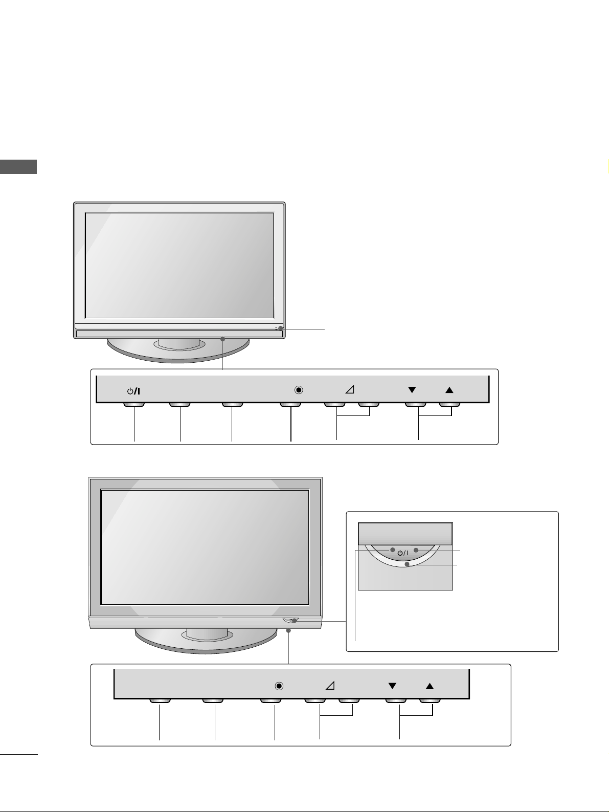
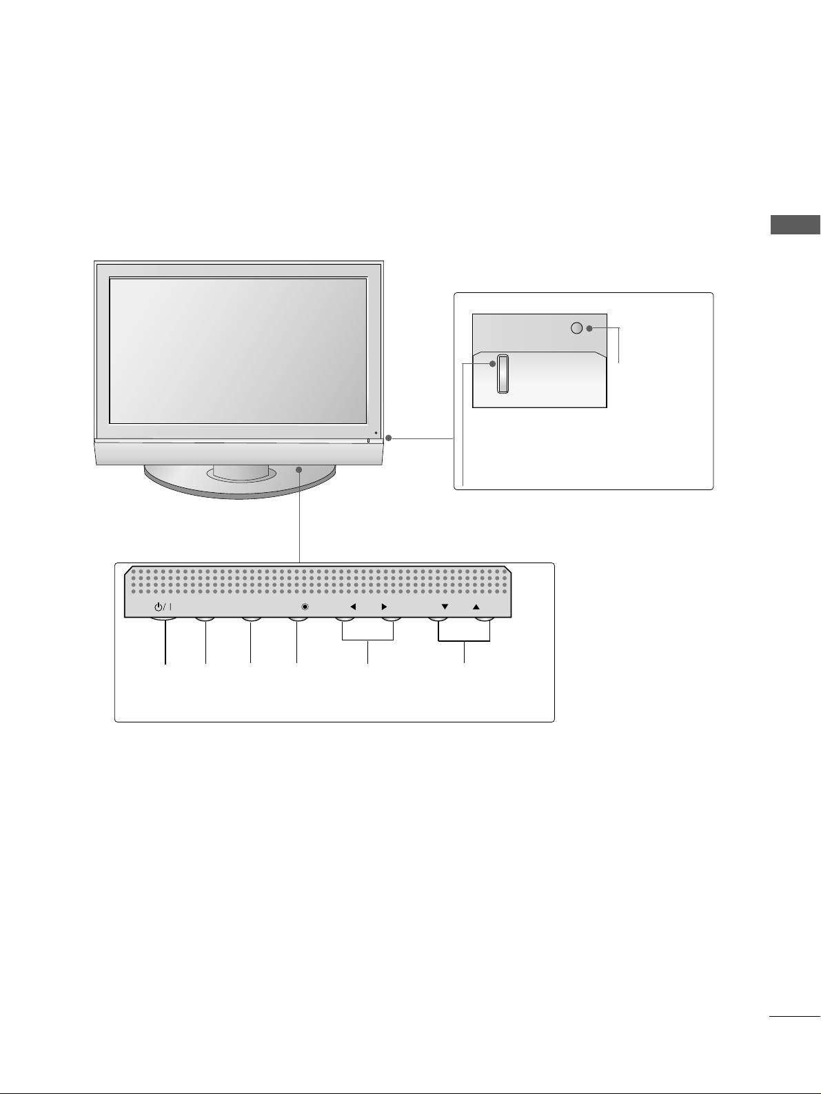
FRONT PANEL CONTROLS
PREPARATION
PREPARATION
■
This is a simplified representation of the front panel. Image shown may differ from your TV.
■
If your product has a protection film attached, remove the film and then wipe the product with a polishing
cloth.
PLASMA TV Models: 42/50PG1
***
PROGRAMME
VOLUME
MENU
OK
INPUT
MENU OK INPUT POWER
VOLUME PROGRAMME
Remote Control Sensor
Remote Control Sensor
Power/Standby Indicator
• illuminates red in standby mode.
• illuminates green when the TV is
switched on.
POWER
Power/Standby Indicator
• illuminates red in standby mode.
• illuminates green when the TV is
switched on.
P
- +
OK
OK
MENU
MENU
INPUT
INPUT
P
- +
OK
OK
MENU
MENU
INPUT
INPUT
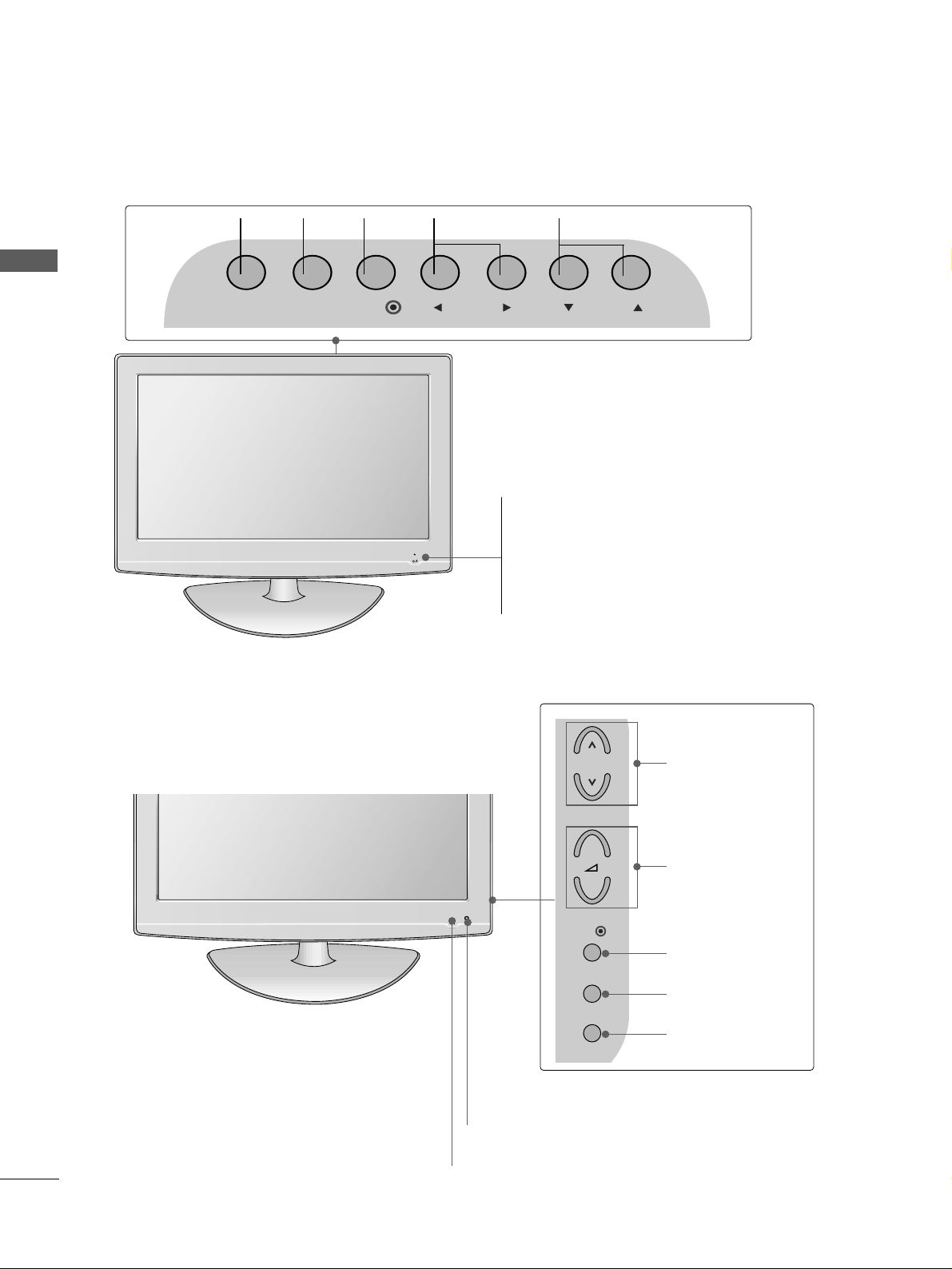
PLASMA TV Models: 42/50PG2
***
5
PREPARATION
PLASMA TV Models: 32PC5
***
Power/Standby Indicator
• illuminates red in standby mode.
• illuminates green when the TV is switched on.
Remote Control
Sensor
INPUT MENU OK VOLUME PROGRAMMEPOWER
PR
VOL
OK
MENU
INPUT
6
PREPARATION
PREPARATION
Intelligent Sensor
Adjusts picture according to the surrounding
conditions (
Only
32/37/42/47/52LG5
***
)
POWER
Remote Control Sensor
Power/Standby Indicator
• illuminates red in standby mode.
• illuminates blue when the TV is switched on.
Note:
You can adjust
PPoowweerr IInnddiiccaattoorr
in
the OPTION menu.
P
MENU
INPUT
OK
+
-
PROGRAMME
VOLUME
OK
MENU
INPUT
INPUT MENU PRVOLOK
PROGRAMMEVOLUME
MENU
OK
INPUT
LCD TV Models : 22LG1
***
, 22LG3
***
LCD TV Models : 26/32/37/42/47LG1
***
,
26/32/37/42/47LG3
***
, 32/37/42/47/52LG5
***
POWER
Remote Control Sensor
Power/Standby Indicator
• illuminates red in standby mode.
• illuminates blue when the TV is switched on.
7
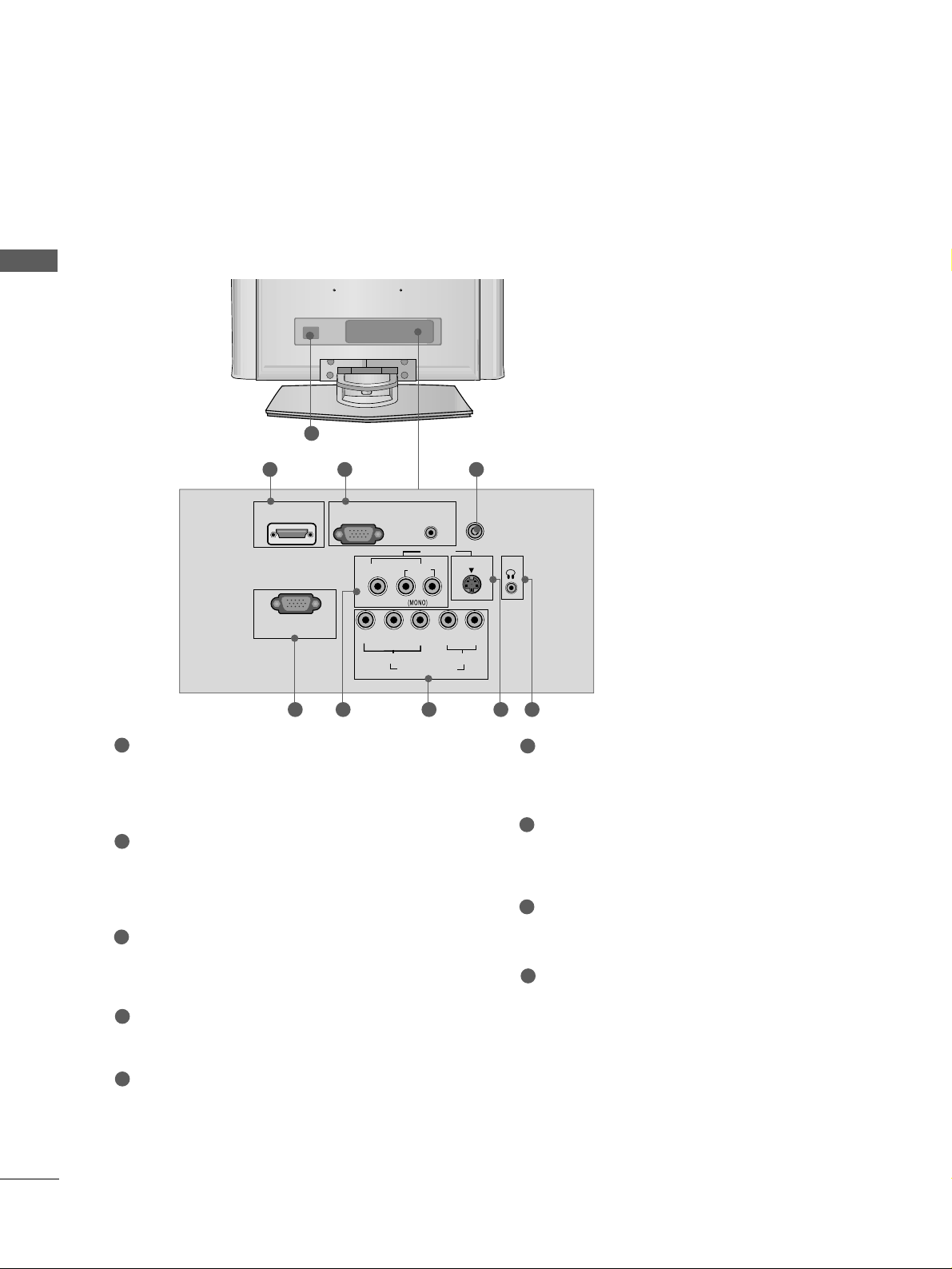
PREPARATION
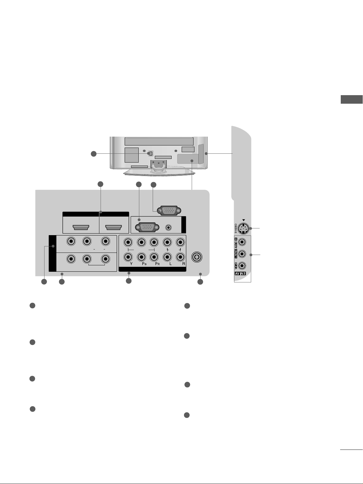
BACK PANEL INFORMATION
A
Image shown may differ from your TV.
PLASMA TV Models
1
HDMI IN HDMI/DVI IN
12
1
2
AUDIO
(RGB/DVI)
RGB
(PC)
RGB IN
COMPONENT IN
ANTENNA
IN
RS-232C IN
(CONTROL)
VIDEO
AUDIO
L( MONO)
R
AUDIO
AUDIO
AV
VIDEO
VIDEO
IN 1
OUT
VARIABLE AUDIO OUT
VARIABLE AUDIO OUT
S-Video Input
Connect S-Video out from
an S-VIDEO device.
Audio/Video Input
Connect audio/video out-
put from an external
device to these jacks.
2
6
5
7
8
3
4
Power Cord Socket
This TV operates on an AC power. The voltage is
indicated on the Specifications page. Never
attempt to operate the TV on DC power.
HDMI Input
Connect a HDMI signal to HDMI IN.
Or DVI(VIDEO)signal to HDMI/DVI port with DVI
to HDMI cable.
RGB/Audio Input
Connect the monitor output from a PC to the
appropriate input port.
RS-232C Input
(CONTROL) Port
Connect the serial port of the control devices to
the RS-232C jack.
(This feature is not available for all models.)
Audio/Video Input (AV IN 1)
Connect audio/video output from an external
device to these jacks.
AV Output
Connect second TV or monitor to the AV OUT
socket on the
TV.
Variable Audio Output
Connect an external amplifier or add a subwoofer
to your surround sound system.
Component Input
Connect a component video/audio device to
these jacks.
Antenna Input
Connect RF antenna to this jack.
1
2
3
4
5
6
7
8
8
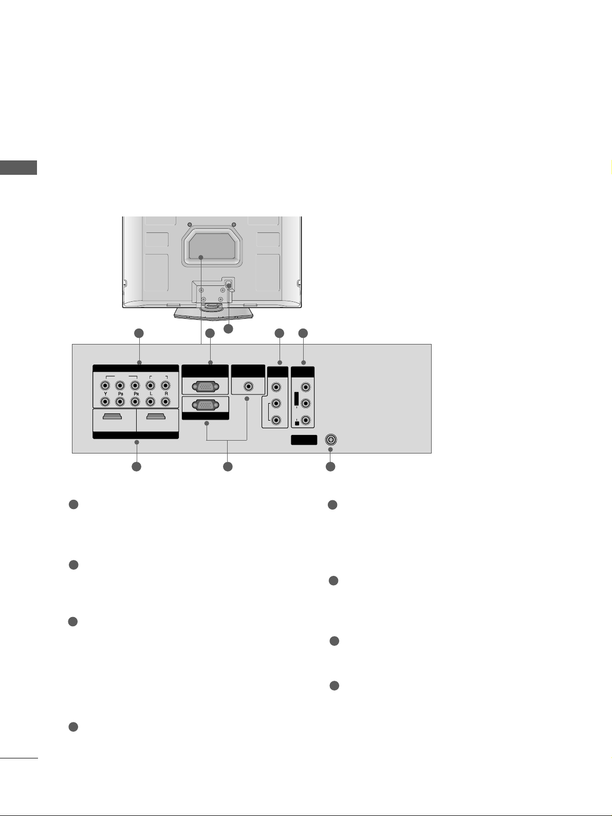
PREPARATION
PREPARATION
8
Component Input
Connect a component video/audio device to
these jacks.
RS-232C Input (CONTROL&SERVICE) Port
Connect the serial port of the control devices to
the RS-232C jack.
AV Output
Connect second TV or monitor to the AV OUT
socket on the
TV.
Variable Audio Output
Connect an external amplifier or add a subwoofer
to your surround sound system.
Audio/Video Input (AV IN)
Connect audio/video output from an external
device to these jacks.
HDMI Input
Connect a HDMI signal to HDMI IN.
Or DVI(VIDEO)signal to HDMI/DVI port with DVI
to HDMI cable.
RGB/Audio Input
Connect the monitor output from a PC to the
appropriate input port.
Antenna Input
Connect RF antenna (UHF) to this jack.
Power Cord Socket
This TV operates on an AC power. The voltage is
indicated on the Specifications page. Never
attempt to operate the TV on DC power.
1
2
3
4
5
6
8
7
VIDEO
AUDIO
COMPONENT IN
HDMI INHDMI/DVI IN
12
RGB IN (PC)
1
2
VARIABLE
OUT
VIDEO
AUDIO
COMPONENTCOMPONENT IN IN
HDMI INHDMI/DVI IN
1 2
RGB IN (PC)RGB IN (PC)
ANTENNA
IN
1
2
RS-232C INRS-232C IN
(CONTROL(CONTROL & SER & SERVICE)VICE)
AUDIO INAUDIO IN
(RGB/DVI)(RGB/DVI)
AV OUT
AV IN
L/MONOMONO
R
AUDIOAUDIO
VARIABLE AUDIO OUTVARIABLE AUDIO OUT
VIDEOVIDEO
1 2 3 4
5 76
Only 32PC5
***
BACK PANEL INFORMATION
A
Image shown may differ from your TV.

9
PREPARATION
LCD TV Models
1
3
S-Video Input
Connect S-Video out from
an S-VIDEO device.
Audio/Video Input
Connect audio/video out-
put from an external
device to these jacks.
HDMI Input
Connect a HDMI signal to
HDMI IN.
(This feature is
not available for all models.)
HDMI IN
HDMI IN
HDMI/DVI IN
HDMI/DVI IN
1
1
2
2
AUDIO
RGB
(PC)
RGB IN
RGB IN
COMPONENT IN
COMPONENT IN
AUDIO
VIDEO
L( MONO)
R
AUDIO
AUDIO
ANTENNA
IN
(RGB/DVI)
AV
VIDEO
VIDEO
IN 1
OUT
VARIABLE
VARIABLE
AUDIO OUT
AUDIO OUT
RS-232C IN
(CONTROL)
3 4
2
7
5
Power Cord Socket
This TV operates on an AC power. The voltage is
indicated on the Specifications page. Never
attempt to operate the TV on DC power.
HDMI Input
Connect a HDMI signal to HDMI IN.
Or DVI(VIDEO)signal to HDMI/DVI port with DVI
to HDMI cable.
RGB/Audio Input
Connect the monitor output from a PC to the
appropriate input port.
RS-232C Input
(CONTROL) Port
Connect the serial port of the control devices to
the RS-232C jack.
(This feature is not available for all models.)
Audio/Video Input (AV IN 1)
Connect audio/video output from an external
device to these jacks.
AV Output
Connect second TV or monitor to the AV OUT
socket on the
TV.
Variable Audio Output
Connect an external amplifier or add a subwoofer
to your surround sound system.
Component Input
Connect a component video/audio device to
these jacks.
Antenna Input
Connect RF antenna to this jack.
1
2
3
4
5
6
7
8
6
8
10
PREPARATION
PREPARATION
Only 22LG1
***
,
22LG3
***
1
RGB (PC) IN
S-VIDEO
AV IN
VIDEO
L
R
AUDIO
Y
P
B
P
R
LR
VIDEO
COMPONENT IN
AUDIO
HDMI/DVI IN
AUDIO
(RGB/DVI) IN
H/P
ANTENNA IN
RS-232C IN
(CONTROL&SERVICE)
Power Cord Socket
This TV operates on an AC power. The voltage is
indicated on the Specifications page. Never
attempt to operate the TV on DC power.
HDMI Input
Connect a HDMI signal to HDMI IN.
Or DVI(VIDEO)signal to HDMI/DVI port with DVI
to HDMI cable.
RGB/Audio Input
Connect the monitor output from a PC to the
appropriate input port.
Antenna Input
Connect RF antenna to this jack.
RS-232C Input
(CONTROL&SERVICE) Por t
Connect the serial port of the control devices to
the RS-232C jack.
Audio/Video Input
Connect audio/video output from an external
device to these jacks.
Component Input
Connect a component video/audio device to
these jacks.
S-Video Input
Connect S-Video out from an S-VIDEO device.
Headphone Input
1
2
3
4
5
6
7
8
9
2
6
43
5 7 8 9
BACK PANEL INFORMATION
A
Image shown may differ from your TV.
11
PREPARATION
■
Image shown may differ from your TV
■
When assembling the desk type stand, check whether the bolt is fully tightened. (If not tightened fully, thep
roduct can tilt forward after the product installation.) If you tighten the bolt with excessive force, the boltcan
deviate from abrasion of the tightening part of the bolt.
1
3
4
Carefully place the TV screen side down on a
cushioned surface to protect the screen from
damage.
2
Assemble the parts of the
SS ttaa nndd BB oodd yy
with
the
CCoovvee rr BB aassee
of the TV.
Assemble the TV as shown.
Fix the 4 bolts securely using the holes in the
back of the TV.
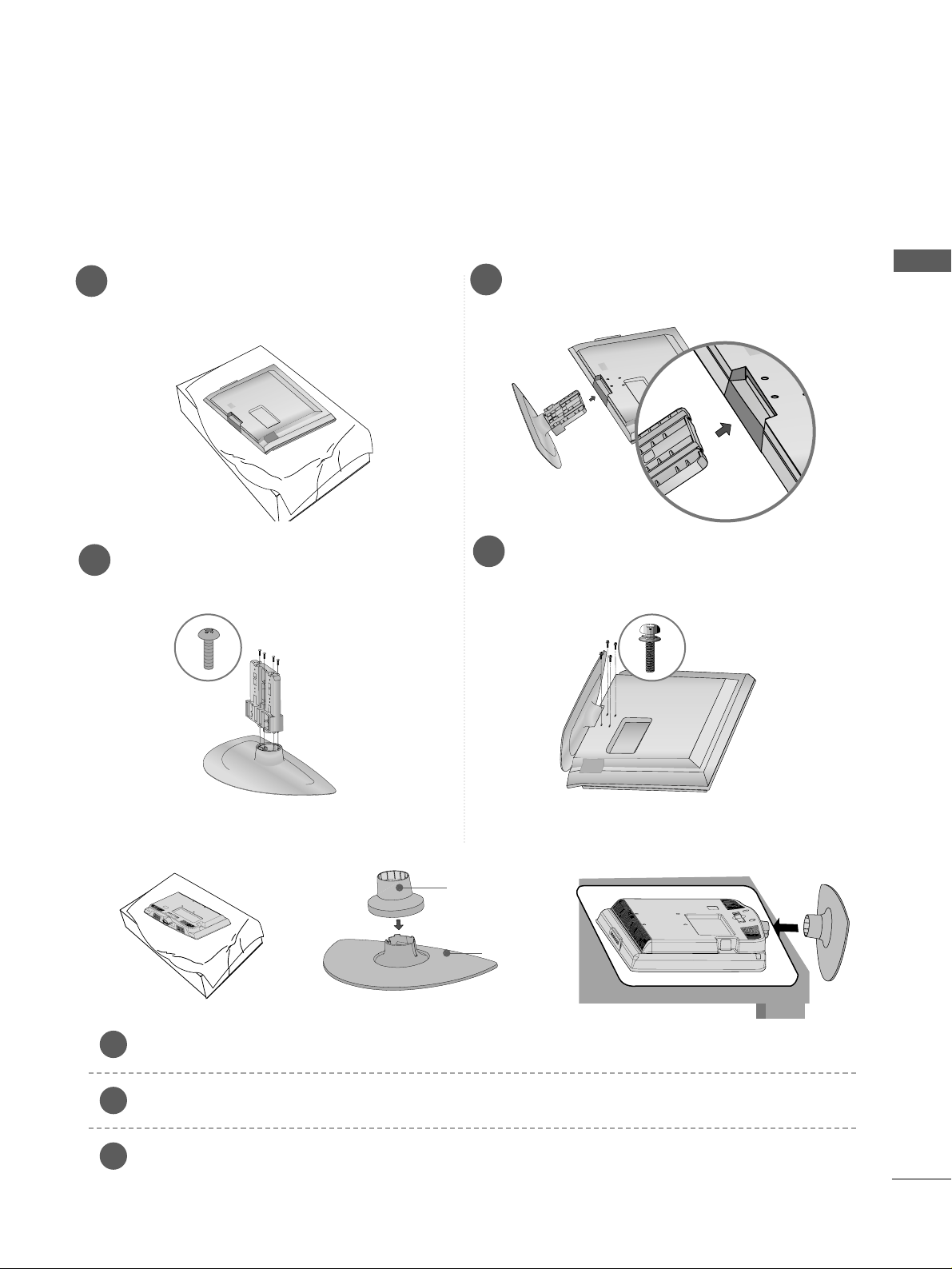
STAND INSTALLATION
LCD TV Models:
26/32/37/42LG1
***,
26/32/37/42LG3
***,
32/37/42LG5
***
(Only 22LG3
***
)
Carefully place the TV screen side down on a cushioned surface to protect the screen from damage.
Assemble the parts of the
SSTTAANNDD BBOODDYY
with
CCOOVVEERR BBAASSEE
of the TV. Insert the
SSTTAANNDD BBOODDYY
into a
CCOOVVEERR BBAASSEE
until clicking sound.
Assemble the TV as shown.
1
2
3
Stand Body
Cover Base
12
PREPARATION
PREPARATION
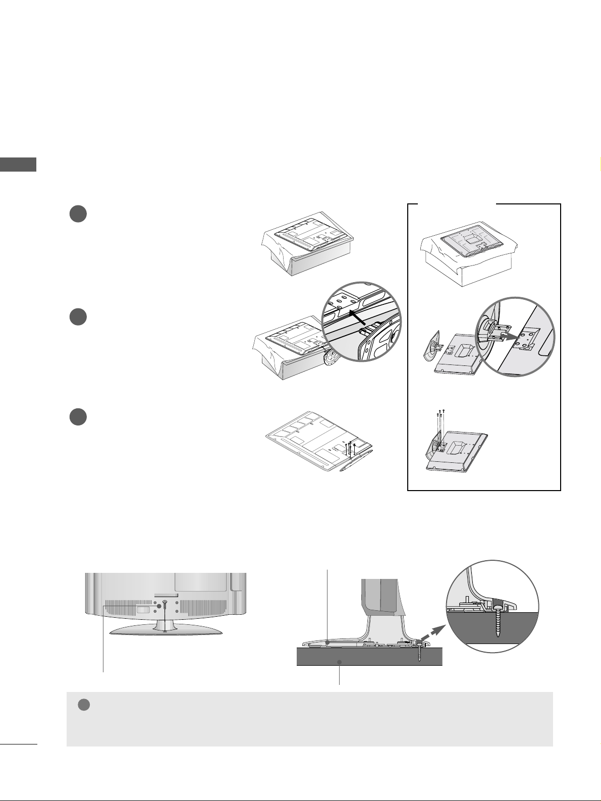
STAND INSTALLATION
PLASMA TV Models (Only 42PG1
***
, 42PG2
***
, 32PC5
***
)
■
Image shown may differ from your TV
■
When assembling the desk type stand, check whether the bolt is fully tightened. (If not tightened fully, thep
roduct can tilt forward after the product installation.) If you tighten the bolt with excessive force, the boltcan
deviate from abrasion of the tightening part of the bolt.
Carefully place the TV screen side
down on a cushioned surface to
protect the screen from damage.
Assemble the TV as shown.
Fix the 4 bolts securely using
the holes in the back of the TV.
1
2
3
Attaching the TV to a desk (Only 26/32/42LG1
***
, 26/32/37/42LG3
***
, 32/37/42LG5
***
)
The TV must be attached to desk so it cannot be pulled in a forward/backward direction, potentially causing
injury or damaging the product. Use only an attached screw.
1-Screw
(provided as parts of the product)
Desk
Stand
WARNING
!
GG
To prevent TV from falling over, the TV should be securely attached to the floor/wall per installation
instructions. Tipping, shaking, or rocking the machine may cause injury.
Only 32PC5
***
13
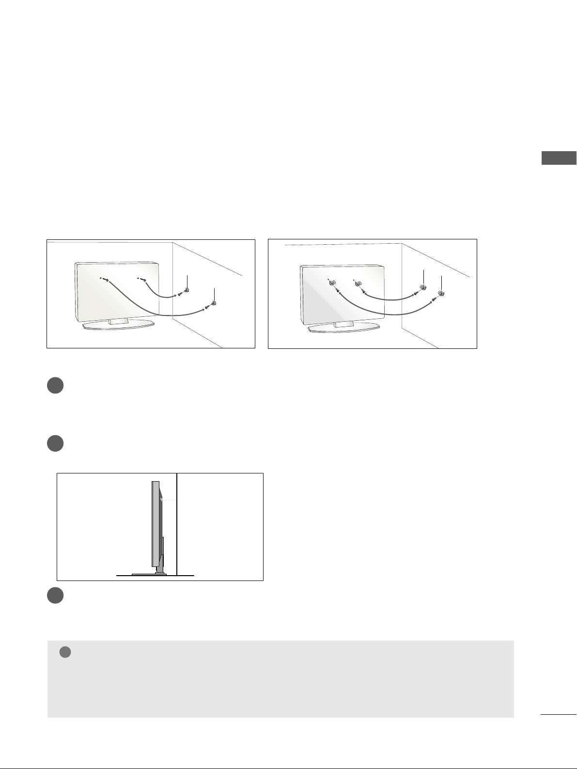
PREPARATION
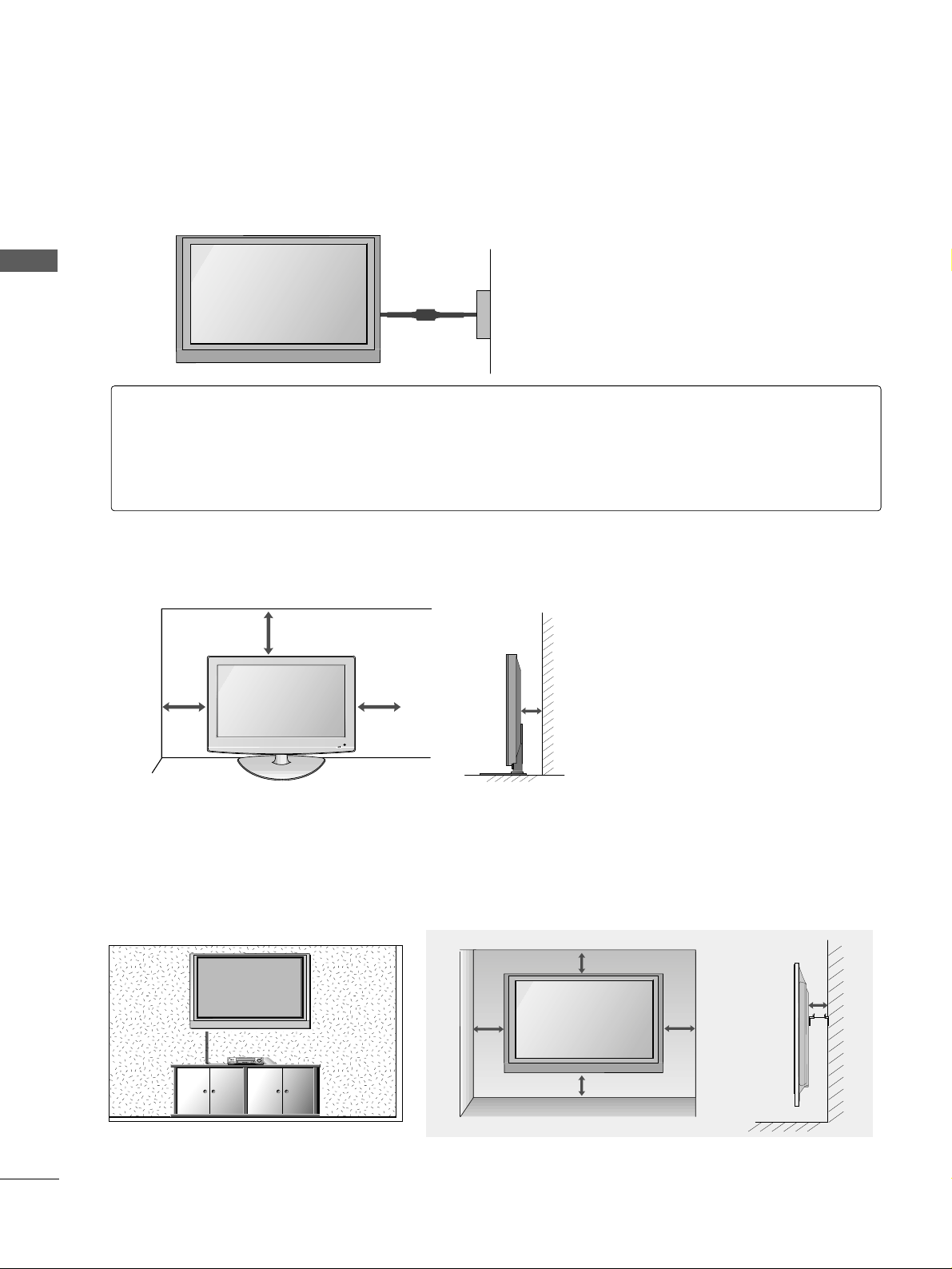
PLEASE SET IT UP CAREFULLY SO THE PRODUCT DOES NOT
FALL OVER.
A
You should purchase necessary components to fix the TV to the wall on the market.
A
Position the TV close to the wall to avoid the possibility of it falling when pushed.
A
The instructions shown below are a safer way to
set
up the TV, which is to fix it to the wall, avoiding the
possibility of it falling forwards if pulled. This will prevent the TV from falling forward and causing injury.
This will also prevent the TV from damage. Ensure that children do not climb or hang from the TV.
NOTE
!
G
When moving the TV undo the cords first.
G
Use a platform or cabinet string and large enough to support the size and weight of the TV.
G
To use the TV safely make sure that the height of the bracket on the wall and on the TV is the same.
3
1
2
Use the eye-bolts or TV brackets/bolts to fix the product to the wall as shown in the picture.
(If your TV has bolts in the eyebolts, loosen then bolts.)
* Insert the eye-bolts or TV brackets/bolts and tighten them securely in the upper holes.
Secure the wall brackets with bolts to the wall.
Ensure that both brackets are even.
3
Use a strong cord to secure the TV.
Secure the cord in such a way that it becomes taught when the TV is in position.
2
1
2
1
14
PREPARATION
PREPARATION
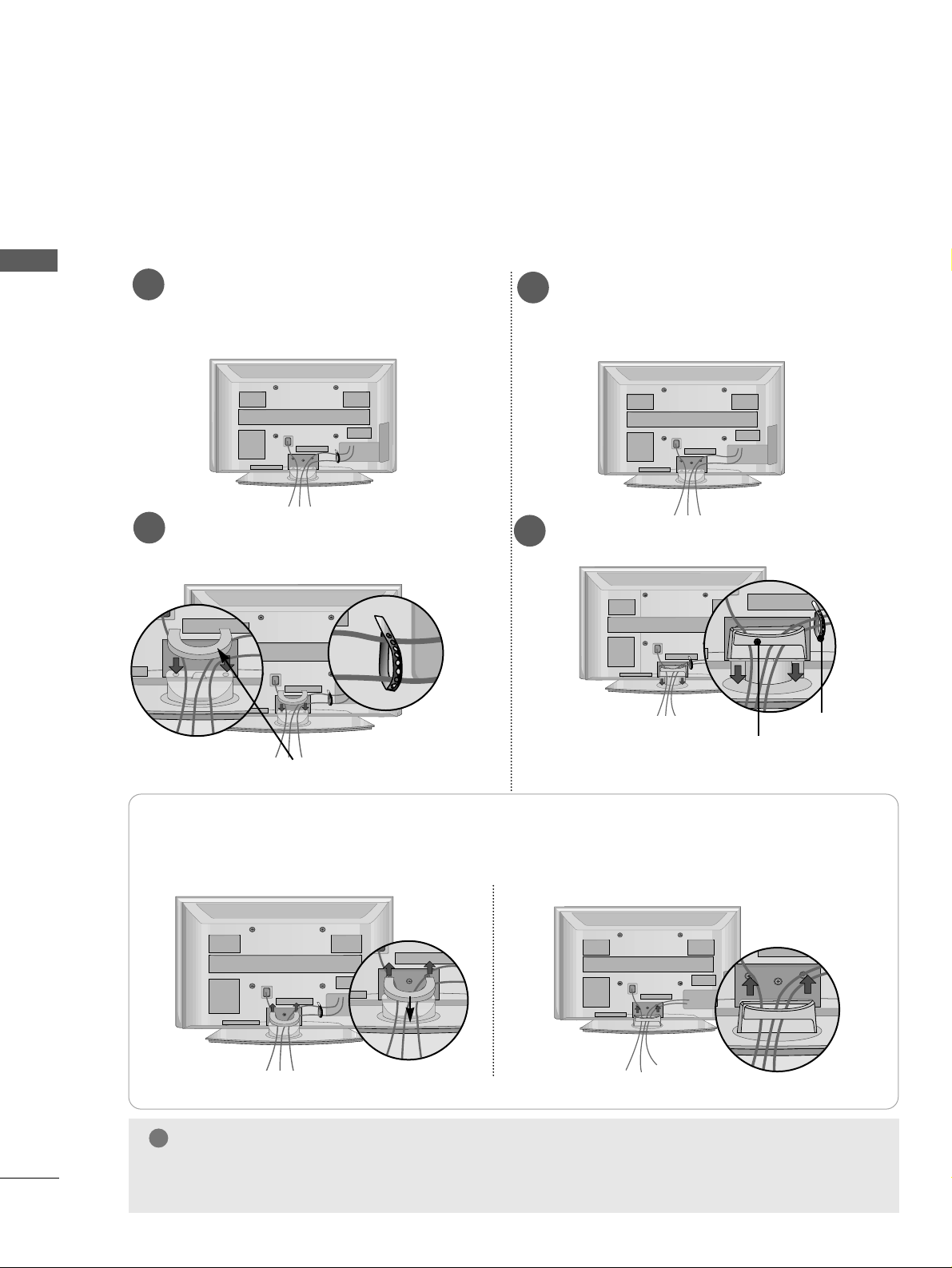
BACK COVER FOR WIRE ARRANGEMENT
■
Here shown may be somewhat different from your TV.
PLASMA TV Models
Connect the cables as necessary.
To connect additional equipment, see the
EExxtteerrnn aall EE qquuiipp mmee nntt SSee ttuupp
section.
1
Install the
CCAABBLLEE MMAANNAAGGEEMMEENNTT CCLLIIPP
as shown.
2
Install the
CCAABBLLEE MMAANNAAGGEEMMEENNTT CCLLIIPP
as shown.
2
Hold the
CCAA BB LLEE MMAANN AAGGEEMMEE NNTT CCLL IIPP
with both hands and pull it upward.
NOTE
!
GG
Do not use the CABLE MANAGEMENT CLIP to lift the TV.
- If the TV is dropped, you may be injured or the TV may be damaged.
How to remove the cable management clip
CABLE MANAGEMENT CLIP
* For the 42PG1
***
model, press the center of the CABLE MANAGEMENT CLIP and then lift up it.
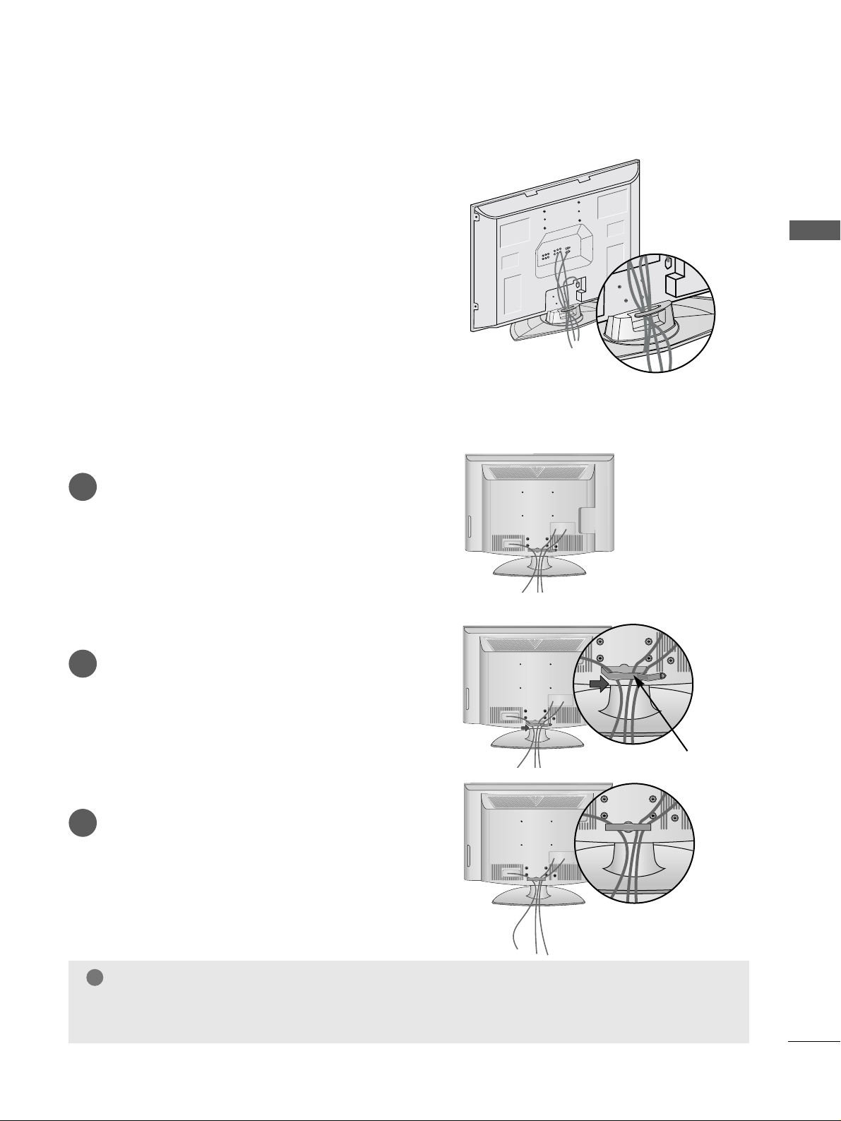
Fix the
CCaabbllee
HHoollddee rr
as shown and
bundle the cables.
Connect the cables as necessary.
To connect additional equipment, see the
EExxtteerrnn aall EE qquuiipp mmee nntt SSee ttuupp
section.
1
42/50PG2
***
42/50PG1
***
CABLE MANAGEMENT CLIP
Fix the
CCaabbll ee HHoollddeerr
as
shown and bundle the
cables.
15
PREPARATION
Only
32PC5
***
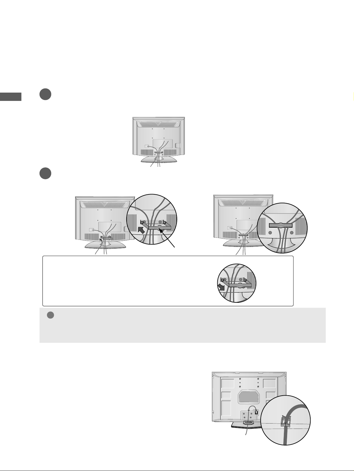
LCD TV Models
Connect the cables as necessary.
To connect additional equipment, see the
External Equipment Setup section of the
manual.
1
Open the
CCAA BB LLEE MMAANN AAGGEEMMEE NNTT CCLL IIPP
as
shown and manage the cables.
2
CABLE MANAGEMENT CLIP
Fit the
CCAA BB LLEE MMAANN AAGGEEMMEE NNTT CCLL IIPP
as
shown.
3
NOTE
!
GG
Do not use the CABLE MANAGEMENT CLIP to lift the TV.
- If the TV is dropped, you may be injured or the TV may be damaged.
Arrange the cables as shown picture.
16
PREPARATION
PREPARATION
PREPARATION
BACK COVER FOR WIRE ARRANGEMENT
Only 22LG3
***
Connect the cables as necessary.
To connect additional equipment, see the External Equipment Setup section of the manual.
1
Install the
CCAA BBLLEE MMAANN AAGGEE MMEENN TT CC LLIIPP
as shown.
2
CABLE MANAGEMENT CLIP
NOTE
!
GG
Do not use the CABLE MANAGEMENT CLIP to lift the TV.
- If the TV is dropped, you may be injured or the TV may be damaged.
How to remove the CABLE MANAGEMENT CLIP
GG
Hold the CABLE MANAGEMENT CLIP with both
hands and pull it backward.
POWER CORD ARRANGEMENT (
Only
32PC5
***
)
After connecting the power cord to the AC input
terminal, fix the power cord at the rear side Hole of
the TV by using the bracket for fixing the power
cord.
17
PREPARATION
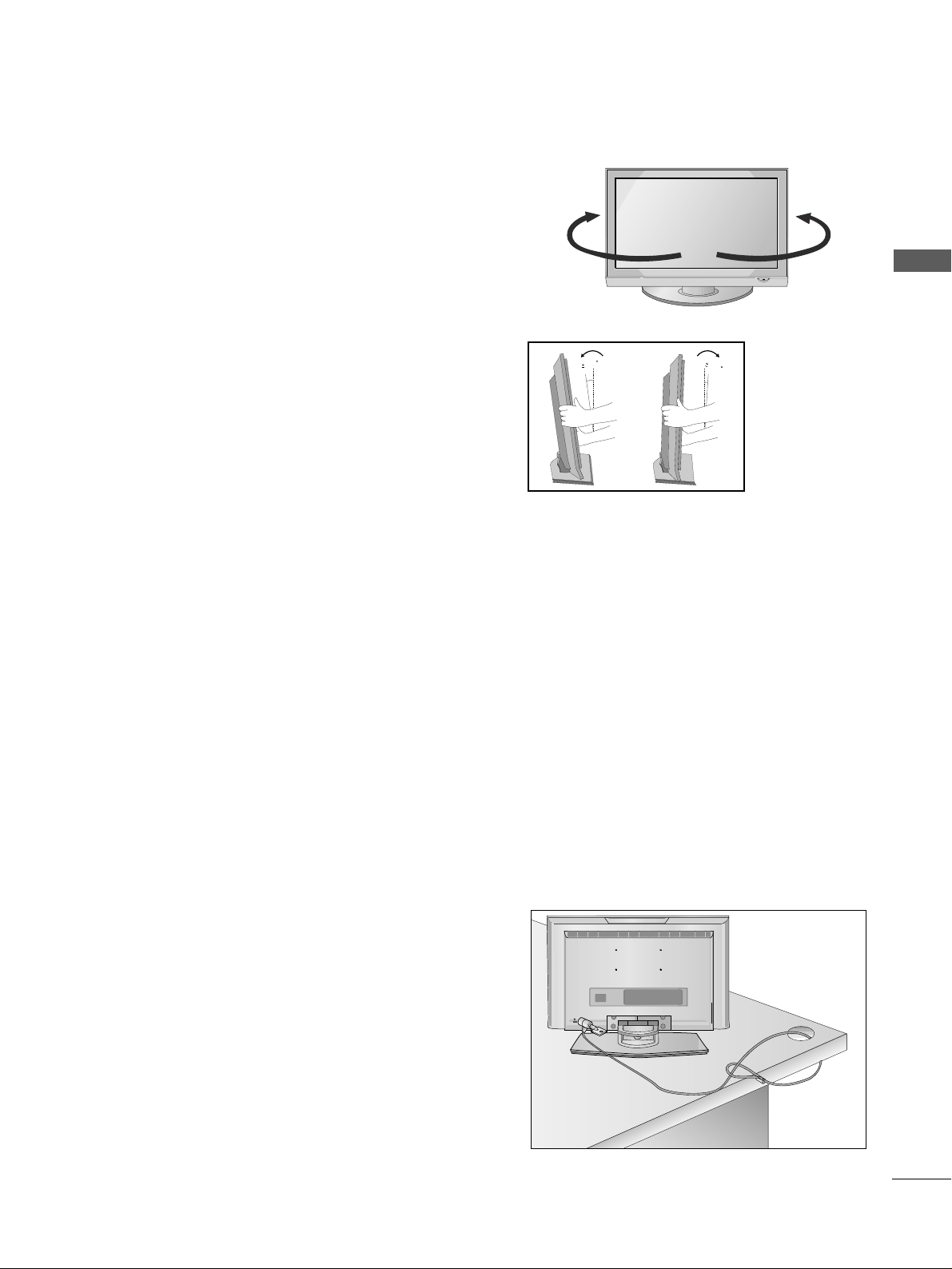
SWIVEL STAND
This feature is not available for all models.
After installing the TV, you can adjust the TV manually
to the left or right direction by 20 degrees to suit your
viewing position.
POSITIONING YOUR
DISPLAY
(Only 22LG1
***
,22LG3
***
)
■
Image shown may differ from your TV.
■
Adjust the position of the panel in various ways for
maximum comfort.
• Tilt range
12
1.5
3
1.5
LOCATION
(Only 22LG1
***
, 22LG3
***
)
Position your TV so that no bright light or sunlight falls directly onto the screen. Care should be taken not to
expose the tv to any unnecessary vibration, moisture, dust or heat. Also ensure that the TV is placed in a position
to allow a free flow of air. Do not cover the ventilation openings on the back cover.
If you intend to mount the TV to a wall, attach VESA standard mounting interface (optional parts) to the back of
the TV.
When you install the TV to use the wall mounting bracket (optional parts), fix it carefully so as not to drop.
KENSINGTON SECURITY SYSTEM
(Only 22LG1
***
, 22LG3
***
)
The TV is equipped with a Kensington Security System connector on the back panel. Connect the Kensington
Security System cable as shown below.
For the detailed installation and use of the Kensington Security System, refer to the user’s guide provided with
the Kensington Security System.
For further information, contact http://www.kensington.com, the internet homepage of the Kensington
company. Kensington sells security systems for expensive electronic equipment such as notebook PCs and LCD
projectors.
NOTE
- The Kensington Security System is an optional accessory.
NOTES
a. If the TV feels cold to the touch, there may be a small “flicker”
when when it is turned on.
This is normal, there is nothing wrong with TV.
b. Some minute dot defects may be visible on the screen, appear-
ing as tiny red, green, or blue spots. However, they have no
adverse effect on the monitor's performance.
c. Avoid touching the LCD screen or holding your finger(s)
against it for long periods of time.
Doing so may produce some temporary distortion effects on
the screen.
18
PREPARATION
PREPARATION
PREPARATION
■
The TV can be installed in various ways such as on a wall, or on a desktop etc.
■
The TV is designed to be mounted horizontally.
DESKTOP PEDESTAL INSTALLATION
For adequate ventilation allow a clearance of 4” (10cm) all around the TV .
4 inches
4 inches
4 inches
4 inches
Power Supply
Circuit breaker
EARTHING
Ensure that you connect the earth wire to prevent possible electric shock. If grounding methods are not
possible, have a qualified electrician install a separate circuit breaker.
Do not try to earth the TV by connecting it to telephone wires, lightening rods or gas pipes.
4 inches
4 inches
4 inches
4 inches
4 inches
WALL MOUNT: HORIZONTAL INSTALLATION
For adequate ventilation allow a clearance of 4” (10cm) all around the TV. We recommend that you use a wall
mounting bracket of LG brand when mounting the TV to a wall.
19
PREPARATION
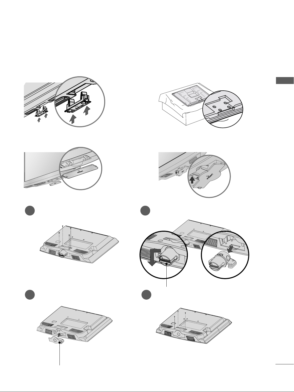
When installing the wall-mounted unit, use the protection cover for desk-type stand installation.
NOT USING THE DESK-TYPE STAND
Plasma TV Models
LCD TV Model
or
or
Only 22LG3
***
Loose the bolts from TV.
1
Bend the
HHIINN GGEE BBOO DDYY
and pull it backward.
2
Insert the
PPRR OOTTEECCTTIIOONN CCOOVVEERR
into
the TV.
3
Fix the 4 bolts securely using the holes in
the back of the TV.
4
PPRR OOTTEECCTTIIOONN CCOOVVEERR
HHIINN GGEE BBOO DDYY
Insert the PROTECTION COVER into the TV
until clicking sound.
RGB IN
ANTENNA
IN
20
PREPARATION
PREPARATION
PREPARATION
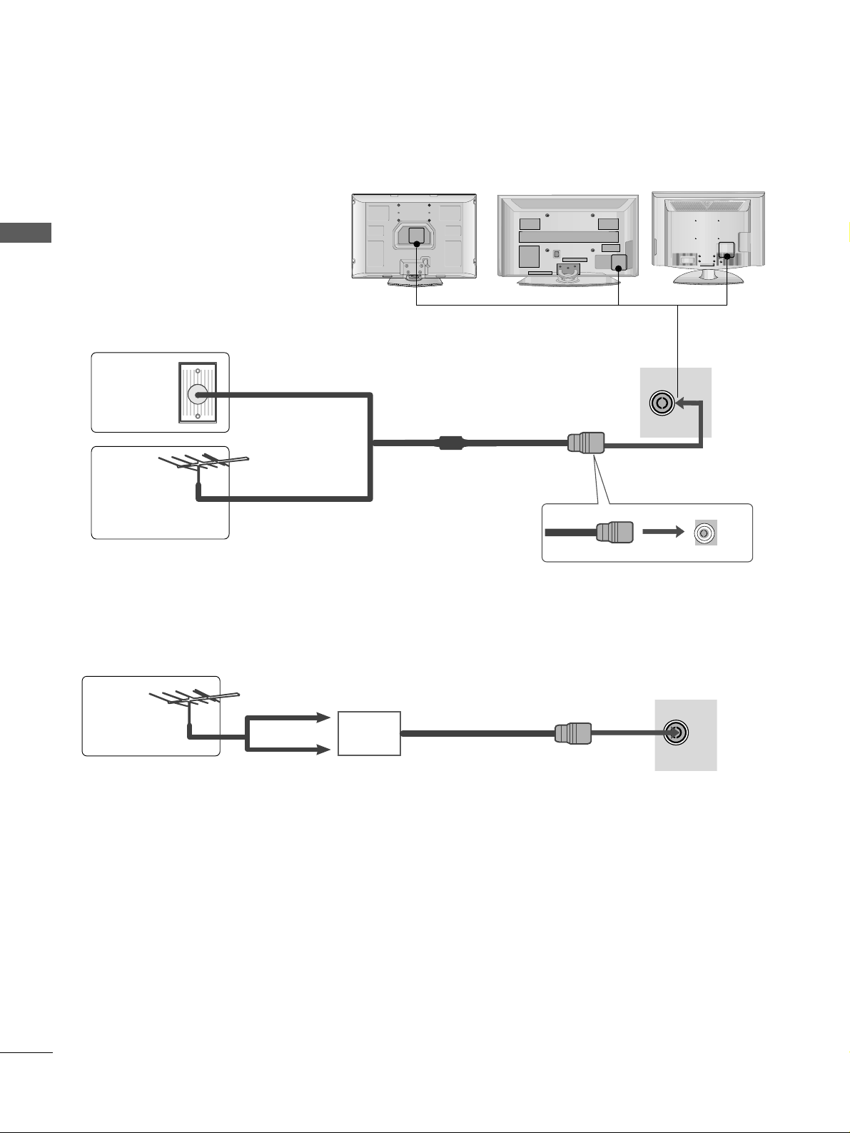
ANTENNA CONNECTION
■
For optimum picture quality, adjust
antenna direction.
■
An antenna cable and converter are
not supplied.
■
To prevent damage do not connect to the mains outlet until all connections are made between the devices.
RGB IN
ANTENNA
IN
Multi-family Dwellings/Apartments
(Connect to wall antenna socket)
Single-family Dwellings /Houses
(Connect to wall jack for outdoor antenna)
Outdoor
Antenna
Wall
Antenna
Socket
RF Coaxial Wire (75 ohm)
Antenna
UHF
Signal
Amplifier
VHF
■
In poor signal areas, to achieve better picture quality it may be necessary to install a signal amplifier to the
antenna as shown above.
■
If signal needs to be split for two TVs,use an antenna signal splitter for connection.
21
EXTERNAL EQUIPMENT SETUP
EXTERNAL EQUIPMENT SETUP
■
To avoid damaging any equipment, never plug in any power cords until you have finished connecting all equipment.
■
This section on EXTERNAL EQUIPMENT SETUP mainly uses diagrams for the PLASMA TV models.
■
Image shown may differ from your TV.
L/MONO
R
AUDIO
VIDEO
VARIABLE AUDIO OUT
HDMI IN HDMI DVI IN
HDMI/DVI IN
1
1
2
COMPONENT IN
VIDEO
AUDIO
1 2
HD RECEIVER SETUP
Connecting with a component cable
Connect the video outputs
(
Y, P
B, PR
)
of the digital TV
top box to the
CCOOMMPPOONN EE NNTT IINN VVIIDDEEOO
jacks on the TV.
Connect the audio output of the digital set-top box to
the
CCOOMMPPOONN EE NNTT IINN AAUU DDIIOO
jacks on the TV.
Turn on the digital set-top box.
(
Refer to the owner’s manual for the digital set-top box.
)
Select
CCoommppoonneenntt11
input source using the
IINNPPUU TT
button on the remote control.
If connected to
CCOOMMPPOONN EENN TT IINN 22
, select
CCoommppoonneenntt22
input source(Except 22LG3
***
).
2
3
4
1
Signal
480i/576i
480p/576p
720p/1080i
10 8 0 p
Component
Yes
Yes
Yes
Yes
(Only 50Hz, 60Hz)
HDMI1/DVI, HDMI2(Except 22LG3
***
),
HDMI3(Only 32/37/42/47/52LG5
***
)
No
Yes
Yes
Yes
(24Hz, 30Hz, 50Hz, 60Hz)
(22LG3
***
- Only 50Hz, 60Hz)
Y
P
B
P
R
LR
VIDEO
COMPONENT IN
AUDIO
1 2
Only 22LG3
***
VIDEOVIDEO
AUDIOAUDIO
COMPONENT IN
1 2
RGBRGB IN (PC)
ANTENNA
IN
1
2
RSRS-232C IN
(CONTR(CONTROL&SERVICE)
AUDIO IN
(RGB/DVI)
AV OUT
AV IN
VIDEO
AUDIO
COMPONENT IN
RGB IN (PC)
ANTENNA
1
2
AV OUT
AV IN
12
AUDIO IN
(RGB/DVI)
HDMI INHDMI/DVI IN
HDMI INHDMI/DVI IN
RS-232C IN
(CONTROL&SERVICE)
1
2
Only 32PC5
***
L/L/MONOMONO
R
AUDIOAUDIO
VIDEOVIDEO
AV
IN 1
OUT
VARIABLE ARIABLE AUDIO OUTAUDIO OUT
L/MONO
R
AUDIO
VIDEO
VARIABLE AUDIO OUT
HDMI IN HDMI DVI IN
HDMI/DVI IN
1
HDMI IN HDMI DVI IN
HDMI IN HDMI IN HDMI/DVI IN HDMI/DVI IN
1 2
1
22
EXTERNAL EQUIPMENT SETUP
EXTERNAL EQUIPMENT SETUP
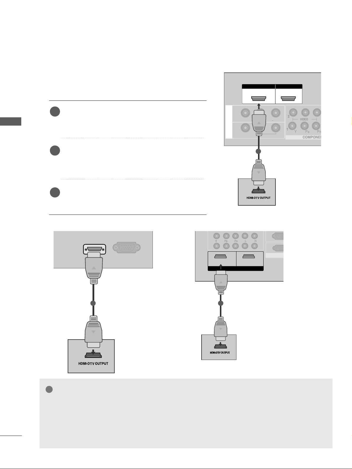
Connecting a set-top box with a HDMI cable
Connect the HDMI output of the digital set-top box to the
HHDDMMII//DDVVII IINN 11,, HHDDMMII IINN 22
(Except 22LG3***) or
HHDDMMII IINN 33
(
Only 32/37/
42/47/52LG5
***
) jack on the TV.
Select
HHDDMMII11// DDVV II ,, HH DD MMII22
(Except 22LG3***) or
HHDDMMII33
(
Only 32/37/
42/47/52LG5
***
) input source
using the
IINNPPUUTT
button on the remote control.
Turn on the digital set-top box.
(
Refer to the owner’s manual for the digital set-top box.
)
2
3
1
GG
TV can receive the video and audio signal simultaneously with using a HDMI cable.
GG
If the digital set-top box supports Auto HDMI function, the output resolution of the source device will be
automatically TV to 1280x720p.
GG
If the digital set-top box player does not support Auto HDMI, you need to TV the output resolution
appropriately. To get the best picture quality, adjust the output resolution of the source device to
1280x720p (42LG31F
**
,
32 /
37/42/47/52LG5
***
: 1920x1080i/1080p).
NOTE
!
HDMI/DVI IN
RGB
(PC) IN
1
Only 22LG3
***
VIDEO
AUDIO
COMPONENT IN
12
RGB IN (PC)
ANTENNA
IN
1
2
RS-232C IN
(CONTROL&SERVICE)
AUDIO IN
(RGB/DVI)
AV OUT
AV IN
VIDEO
AUDIO
COMPONENT IN
RGB IN RGB IN (PC)
ANTENNA
IN
1
2
AUDIO IN
(RGB/DVI)
AV OUT
AV IN
1 2
VIDEO
AUDIO
COMPONENT IN
RGB IN (PC)
1
2
12
AUDIO IN
(RGB/DVI)
HDMI INHDMI/DVI IN
HDMI INHDMI/DVI IN
HDMI INHDMI/DVI IN
RS-232C IN
(CONTROL&SERVICE)
RS-232C IN
(CONTROL&SERVICE)
1
Only 32PC5
***
23
EXTERNAL EQUIPMENT SETUP
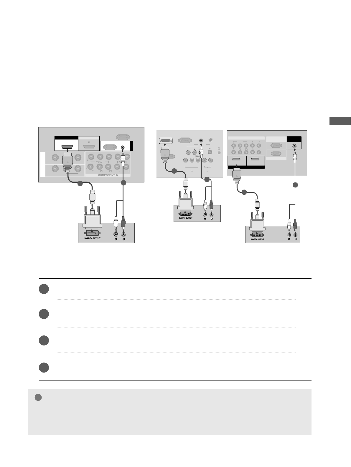
Connect the DVI output of the digital set-top box to the
HHDDMMII//DDVVII IINN 11
jack on the TV.
Connect the audio output of the digital set-top box to the
AA UUDDIIOO(( RR GGBB// DDVVII))
jack on the TV.
Turn on the digital set-top box.
(
Refer to the owner’s manual for the digital set-top box.
)
Select
HHDDMMII11//DDVVII
input source using the
IINNPPUUTT
button on the remote control.
2
3
4
1
Connecting with a HDMI to DVI cable
GG
HDMI2(Except 22LG3***), HDMI3(
Only 32/37/
42/47/52LG5
***
) source does not support DVI source.
GG
If the Set-Top Box has a DVI output and no HDMI output, a separated audio connection is necessary.
GG
If the Set-Top Box does not support Auto DVI, you need to set the output resolution appropriately.
NOTE
!
L/L/MONOMONO
R
AUDIOAUDIO
VIDEOVIDEO
AV
IN 1
OUT
VARIABLE ARIABLE AUDIO OUTAUDIO OUT
HDMI IN HDMI DVI IN
HDMI/DVI IN HDMI/DVI IN
1
AUDIO
(RGB/DVI)
RGB
(PC)
RGB IN
RS-232C IN
(CONTROL)
1
2
S-VIDEO
AV IN
VIDEO
L
R
AUDIO
Y
PB
P
R
LR
VIDEO
COMPONENT IN
AUDIO
HDMI/DVI IN
AUDIO
(RGB/DVI) IN
H/PH/P
ANTENNA
RS-232C IN
(CONTROL&SERVICE)
RGB
(PC) IN
11
2
Only 22LG3
***
VIDEOVIDEO
AUDIO
COMPONENTCOMPONENT IN IN
RGB IN (PC)RGB IN (PC)
ANTENNA
IN
1
2
AV OUT
AV IN
1 2
AUDIO IN
(RGB/DVI)(RGB/DVI)
HDMI INHDMI/DVI IN
RS-232C INRS-232C IN
(CONTROL&SERVICE)
2
Only 32PC5
***
1
1
2
COMPONENT IN
VIDEO
AUDIO
1 2
24
DVD SETUP
EXTERNAL EQUIPMENT SETUP
EXTERNAL EQUIPMENT SETUP
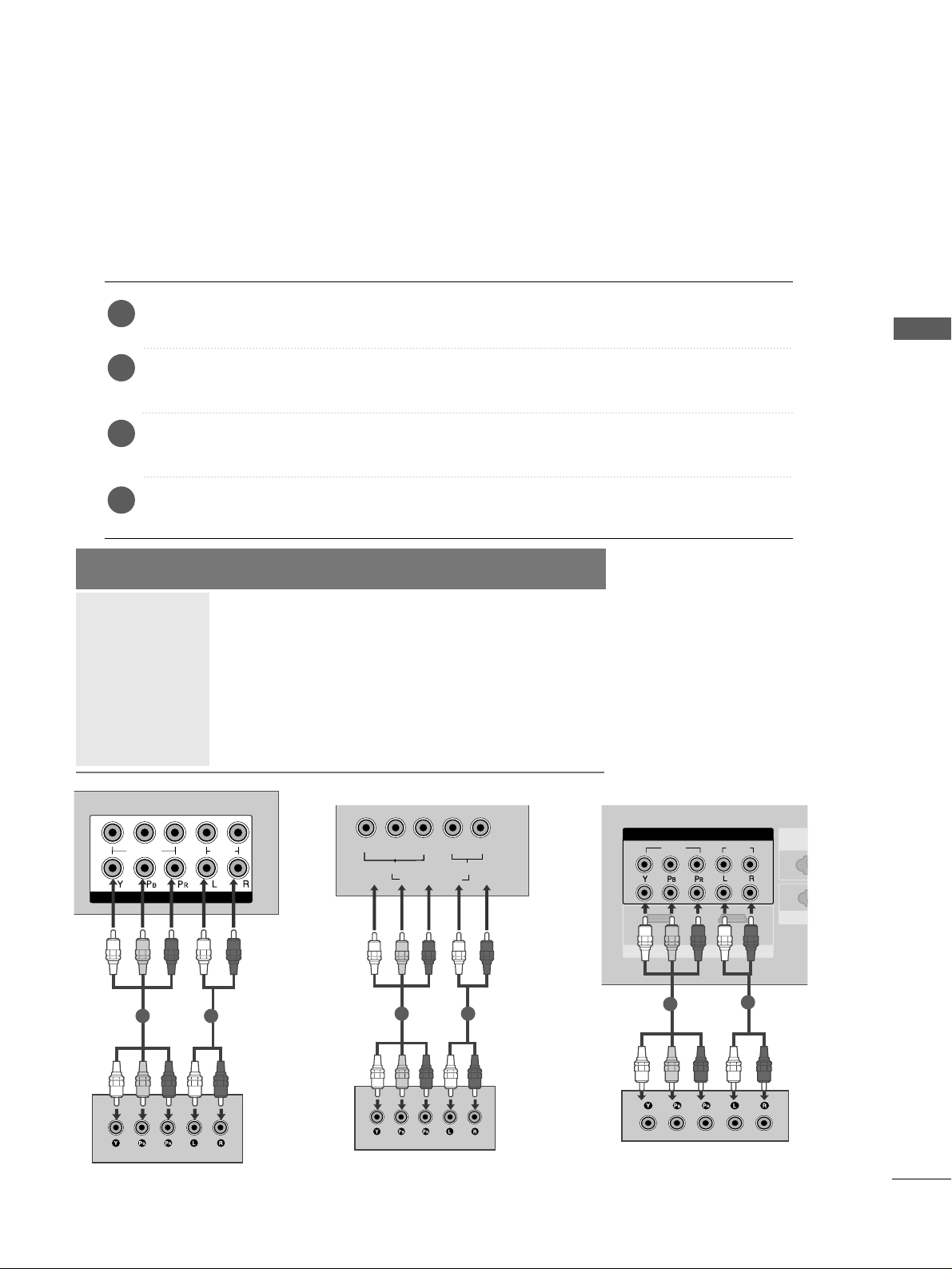
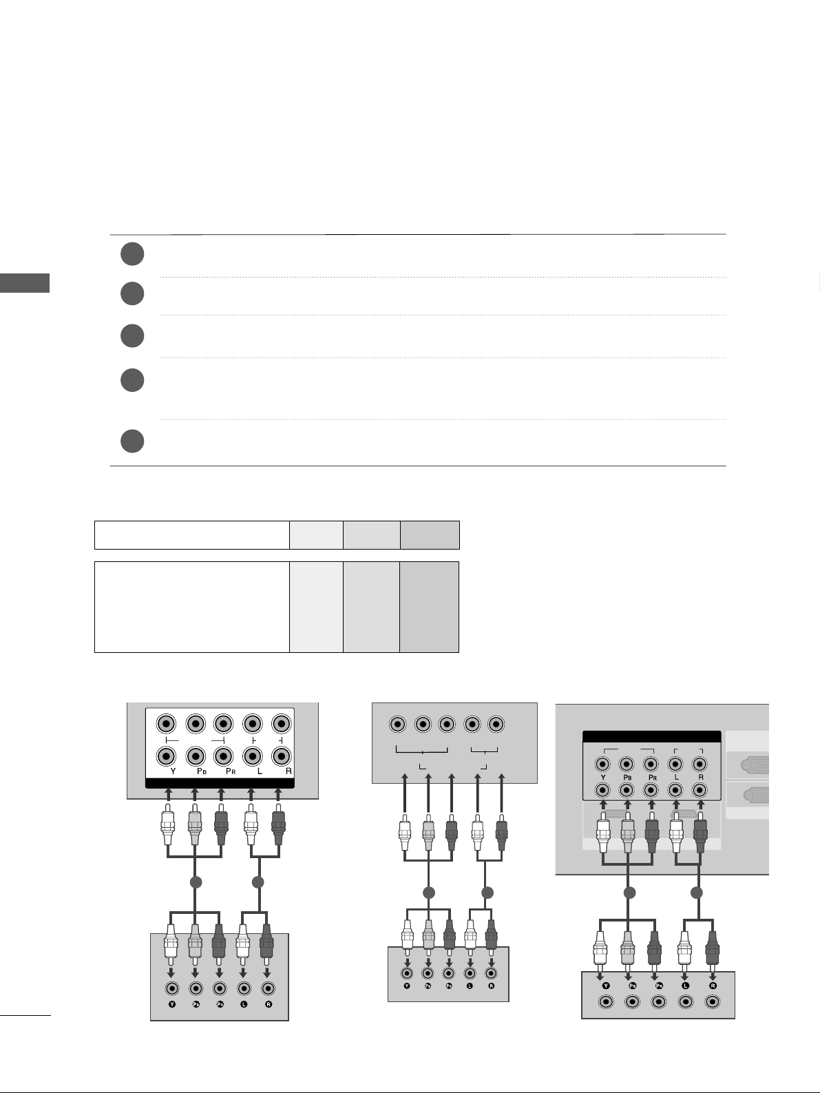
Connecting with a component cable
Component Input ports
To achieve better picture quality, connect a DVD player to the component input ports as shown below.
Component ports on the TV
YP
B
P
R
Video output ports
on DVD player
Y
Y
Y
Y
P
B
B-Y
Cb
Pb
PR
R-Y
Cr
Pr
Connect the video outputs
(
Y, PB
, PR
)
of the DVD to the
CCOOMMPPOONNEENNTT IINN VVIIDDEEOO
jacks on the TV.
Connect the audio outputs of the DVD to the
CCOOMMPPOONN EE NNTT IINN AAUU DDIIOO
jacks on the TV.
Turn on the DVD player, insert a DVD.
Select
CCoommppoonneenntt11
input source using the
IINNPPUUTT
button on the remote control.
If connected to
CCOOMMPPOONN EENN TT IINN 22
, select
CCoommpp oonn eenn tt 22
input source(Except 22LG3***).
Refer to the DVD player's manual for operating instructions.
2
3
4
5
1
Y
P
B
P
R
LR
VIDEO
COMPONENT IN
AUDIO
1 2
Only 22LG3
***
VIDEOVIDEO
AUDIO
COMPONENTCOMPONENT IN
1 2
RGB IN RGB IN (PC)
ANTENNA
IN
1
2
AUDIO IN
(RGB/DVI)
AV OUT
AV IN
HDMI IN
HDMI/DVI IN
RS-232RS-232C IN
(CONTROL&S(CONTROL&SERVICE)
1 2
Only 32PC5
***

25
EXTERNAL EQUIPMENT SETUP
Connecting with a S-Video cable
(Except 32PC5
***
)
Connect the S-VIDEO output of the DVD to the
SS --VVIIDDEEOO
input on the TV.
Connect the audio outputs of the DVD to the
AA UUDDIIOO
input jacks on the TV.
Turn on the DVD player, insert a DVD.
Select
AA VV 22
input source using the
IINNPPUUTT
button on
the remote control.
Refer to the DVD player's manual for operating
instructions.
2
3
4
5
1
AV IN 2
L R
S-VIDEOVIDEO
OUTPUT
SWITCH
ANT IN
ANT OUT
1
2
Only 22LG3
***
S-VIDEO
AV IN
VIDEO
L
R
AUDIO
Y
PB
P
R
LR
VIDEO
COMPONENT IN
AUDIO
H/P
L R
S-VIDEOVIDEO
OUTPUT
SWITCH
ANT IN
1
2
26
EXTERNAL EQUIPMENT SETUP
EXTERNAL EQUIPMENT SETUP
HDMHDMI IN HDMI DVI IN
HDMHDMI IN HDMI/DVI IN HDMI/DVI IN
1 2
HDMI IN HDMI DVI IN
AV IN 2
L/ MONO
R
AUDIO
VIDEO
L/MONO
R
AUDIOAUDIO
VIDEOVIDEO
IN 1
OUT
VARIABLE AUDIO OUT
1
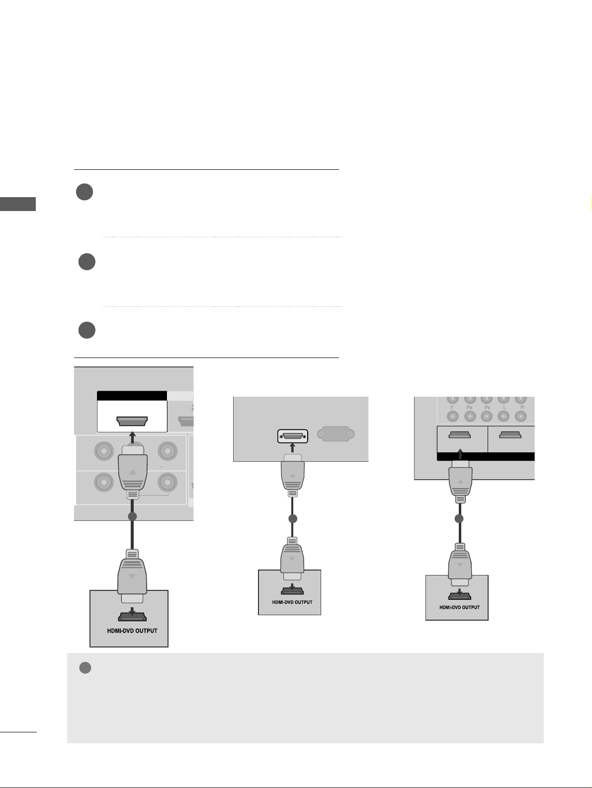
Connecting with a HDMI cable
Connect the HDMI output of the DVD to the
HHDDMMII//DDVVII IINN 11,, HH DDMMII IINN 22
(Except 22LG3***) or
HHDDMMII IINN 33
(
Only 32/37/
42/47/52LG5
***
) jack on the TV.
Select
HHDDMMII11// DDVV II ,, HH DD MMII22
(Except 22LG3***) or
HHDDMMII33
(
Only 32/ 37/
42/47/52LG5
***
) input source
using the
IINNPPUUTT
button on the remote control.
Refer to the DVD player's manual for operating instruc-
tions.
1
GG
The TV can receive video and audio signals simultaneously when using a HDMI cable.
GG
If the DVD player supports Auto HDMI function, the output resolution of the source device will be automati-
cally TV to 1280x720p.
GG
If the DVD player does not support Auto HDMI, you must TV the output resolution appropriately.
To get the best picture quality, adjust the output resolution of the source device to 1280x720p
(42LG31F
**
,
32/37/
42/47/52LG5
***
:1920x1080i/1080p).
NOTE
!
2
3
HDMI IN HDMI DVI IN
AV IN 2
L/MONO
R
AUDIO
VIDEO
HDMI/DVI IN
RGB
(PC) IN
1
Only 22LG3
***
VIDEO
AUDIO
COMPONENT IN
RGB IN (PC)
ANTENNA
IN
1
2
AUDIO IN
(RGB/DVI)
AV OUT
AV IN
1 2
VIDEO
AUDIO
COMPONENT IN
RGB IN (PC)
1
2
12
VIDEO
AUDIO
COMPONENT IN
12
RGB IN (PC)
ANTENNA
IN
1
2
AUDIO IN
(RGB/DVI)
AV OUT
AV IN
HDMI IN
HDMI/DVI IN
HDMI INHDMI/DVI IN
HDMI INHDMI/DVI IN
RS-232C IN
(CONTROL&SERVICE)
RS-232C IN
(CONTROL&SERVICE)
RS-232C IN
(CONTROL&SERVICE)
1
Only 32PC5
***

27
VCR SETUP
EXTERNAL EQUIPMENT SETUP
■
To avoid picture noise (interference), allow adequate distance between the VCR and TV.
■
Typically a frozen still picture from a VCR. If 4:3 picture format is used for an extended period the fixed
images on the sides of the screen may remain visible.
Connect the
AA NN TT OOUUTT
socket of the VCR
to the
AA NN TTEENNNNAA IINN
socket on the TV.
Connect the antenna cable to the
AA NN TT IINN
socket of the VCR.
Press the
PP LLAAYY
button on the VCR and
match the appropriate programme
between the TV and VCR for viewing.
2
3
1
RGB IN
ANTENNA
IN
OUTPUT
SWITCH
ANT IN
S-VIDEO VIDEO
ANT OUT
L
Wall Jack
Antenna
Connecting with a RF cable
1
2
R
H/P
ANTENNA IN
OUTPUT
SWITCH
ANT IN
S-VIDEO VIDEO
ANT OUT
L
Wall Jack
Antenna
1
2
Only 22LG3
***
OUTPUT
SWITCH
ANT IN
R
S-VIDEO VIDEO
ANT OUT
L
ANTENNA
IN
AV IN
L/MO
Wall Jack
Antenna
1
2
Only 32PC5
***

Connecting with a RCA cable
Connect the
AA UUDDIIOO
/
VVIIDD EE OO
jacks between TV and VCR. Match the jack colours (Video = yellow,
Audio Left = white, and Audio Right = red)
Insert a video tape into the VCR and press PLAY on the VCR.
(
Refer to the VCR owner’s manual.
)
Select
AA VV 11
input source using the
IINNPPUUTT
button on the remote control.
If connected to
AA VV IINN22
, select
AA VV 22
input source(Except 32PC5
***
).
1
2
3
GG
If you have a mono VCR, connect the audio cable from the VCR to the
AA UUDDII OO LL// MMOONNOO
jack
of the TV.
NOTE
!
28
EXTERNAL EQUIPMENT SETUP
EXTERNAL EQUIPMENT SETUP
L/MONO
R
AUDIO
VIDEO
VIDEO
L
R
AUDIO
HDMI IN HDMI DVI IN
HDMI IN HDMI DVI IN
L
R
S-VIDEO
VIDEO
OUTPUT
SWITCH
ANT IN
ANT OUT
L/L/MONOMONO
R
AUDIOAUDIO
VIDEOVIDEO
AV
IN 1
OUT
VARIABLE ARIABLE AUDIO OUTAUDIO OUT
L
R
S-VIDEO
VIDEO
OUTPUT
SWITCH
ANT IN
ANT OUT
RGB (PC) IN
S-VIDEO
AV IN
VIDEO
L
R
AUDIO
Y
P
B
P
R
L R
VIDEO
COMPONENT IN
AUDIO
AUDIO
(RGB/DVI) IN
H/P
ANTE
1
1
Only 22LG3
***
L
R
S-VIDEO
VIDEO
OUTPUT
SWITCH
ANT IN
ANT OUT
ANTENNAANTENNA
IN
AV INV IN
L/L/MONOMONO
R
AUDIOAUDIO
VIDEOVIDEO
1
Only 32PC5
***
Loading...