


/
P/NO : MFL63724107(1005-REV00) |
www.lg.com/th |


ที่รีโมตคอนโทรล
Precaution in Installing the Product |
Precautions in Moving the Product |
|
|
WARNING |
WARNING |
|
|
Keep away from heat sources like electrical heaters. |
|
|
Make sure to turn off the product. |
Make sure to remove all cables before moving the |
|
- Electrical shock, fire, malfunction or deformation may occur. |
|
|
|
product.  - You may be electrocuted or the product can be dam-


aged.
Do not use the product in damp place such as a bath-
room or any place where it is likely to get wet. CAUTION
- This may cause a fire or could give an electric shock. Do not shock the product when moving it.
|
|
|
If you can smell smoke or other odors or hear a strange |
- You may be electrocuted or the product can be dam- |
|
|
|
|
|
aged. |
|
|
|
|
sound unplug the power cord and contact the service |
|
|
|
Make the panel face forward and hold it with both |
|
hands to move. |
|
|
center. |
|
|
- If |
|
|
- If you continue to use without taking proper measures, elec- |
cause electric shock or fire. Contact with the service |
|
|
you drop the product, the damaged product can |
|
trical shock or fire can occur.
center for repair.
CAUTION |
|
|
|
|
Precautions in Using the Product |
||
|
|
||
Install the product on a flat and stable place that |
|
WARNING |
|
|
|
|
|
has no risk of dropping the product. |
|
|
|
|
|
|
|
- If the product is dropped, you may be injured or the |
Do not disassemble, repair or modify the product at |
||
|
|||
product may be broken. |
, , , |
||
|
your own discretion. |
|
|
|
|
|
|
|
- Fire or electric shock accident can occur. |
|
|
|
Contact the service center for check, calibration or |
||
Keep the product away from direct sunlight. |
- |
|
|
repair. |
|
||
|
|||
- The product can be damaged. |
|
|
|
|
|
|
|
|
To reduce the risk of fire or electric shock, do not |
||
|
|
||
|
expose this apparatus to rain or moisture. |
|
|
Do not place the product in a built-in installation |
Apparatus shall not be exposed to dripping or |
||
splashing and no objects filled with liquids, such as |
|||
|
|||
such as bookcase or rack. |
vases, shall be placed on the apparatus. |
|
|
Ventilation required. |
|
||
- |
|
|
|
Electrical Power Related Precautions |
|
CAUTION |
|
|
|
|
|
WARNING |
Refer all servicing to qualified service personnel. |
||
|
Servicing is required when the apparatus has been |
||
Make sure to connect the power cable to the ground- , |
|||
ed current. |
damaged in any way, such as power supply cord or plug |
||
( ) |
, , |
||
- You may be electrocuted or injured. |
is damaged, liquid has been spilled or objects have |
||
|
|
||
|
fallen into the apparatus, the apparatus has been |
||
|
exposed to rain or moisture, does not operate normal- |
||
Do not touch the power plug with wet hands.


 Additionally, it the cord pin is wet or covered with ly, or has been dropped.
dust, dry the power plug completely or wipe dust off.
|
IMPORTANT INFORMATION TO PREV NT “IMAGE |
URN |
|
|
- You may be electrocuted due to excess moisture. |
“IMAGE BURN/BURN-IN” |
|
||
|
/BURN-IN” ON YOUR TELEVISION SCREEN |
|
|
|
|
( , , |
|||
|
- When a fixed image (e.g. logos, screen menus, video game, computer |
|
||
|
, |
|||
|
|
|
||
During a thunder or lightning storm, unplug the |
display and teletext pages) is displayed on the television for an extend- |
|
||
ed period it can become permanently imprinted on the screen. This |
“im |
|||
|
||||
burn”phenomenon is known“burn-asin”“image burn” or “burn-in”. Image burn is not |
||||
power cable or signal cable. |
|
|
|
|
- You may be electrocuted or a fire can break out. |
|
|
||
|
|
|
|
|
covered under the manufacturer’s warranty. |
|
|
||
|
- |
|||
|
In order to prevent image burn, avoid displaying a fixed image on your |
|
||
CAUTION |
2 1 |
|||
|
television’s screen for a prolonged period (2 or more hours for LCD, 1 |
|
||
|
|
|
|
|
Protect the power cord from physical or mechanical |
or more hours for Plasma). |
|
|
|
- Image burn can also occur on the letterboxed areas of your television |
|
|||
abuse, such as being twisted, kinked, pinched, closed in |
|
|||
a door, or walked upon. Pay particular attention to plugs, |
4:3 |
|
|
|
, , |
if you use the 4:3 aspect ratio setting for an extended period. |
|
|
|
|
|
|
||
|
|
|
|
|
wall outlets, and the point where the cord exits the |
|
|
|
|
|
|
|
|
|
appliance. |
|
|
|
|
2
CD
|
|
|
|
|
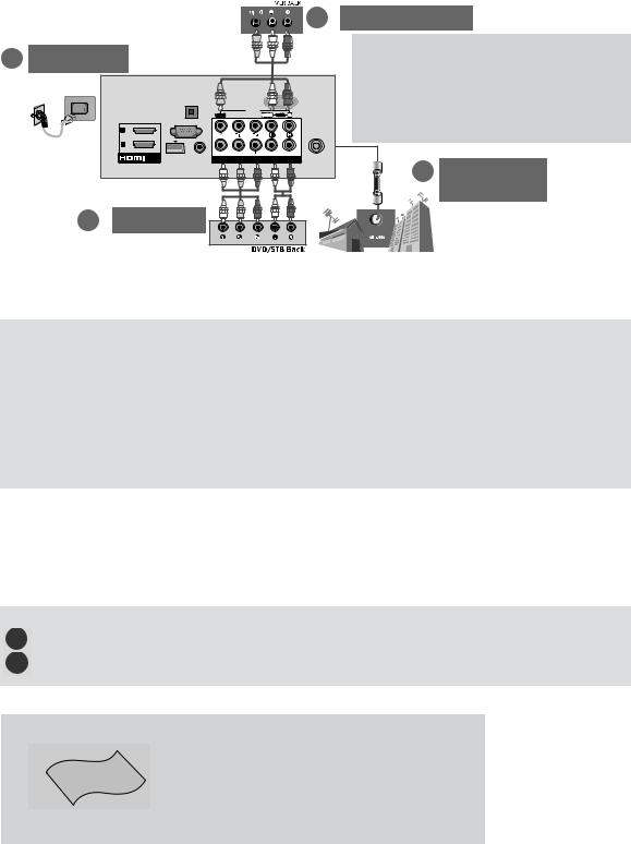
2 VCR Connection |
||
3 Power Cord |
|
|
|
|
|
||
|
|
|
|
|
|||
|
AUDIO OUT |
|
232C |
|
|
1. (Antenna) |
|
|
|
& |
VICE) |
|
2. (DVD |
||
|
OPTICAL |
|
|
|
|
|
|
|
DIGITAL |
|
|
|
|
Set top box |
|
|
RGB IN (PC) |
|
AV IN1 |
|
|
||
|
VIDEO |
|
L/MONO AUDIO |
R |
|
3. (Power Cord) |
|
|
2 |
|
|
2 |
|
||
|
|
|
|
|
|
|
|
|
1 |
|
|
1 |
|
|
|
|
WIRELESS AUDIO IN |
VIDEO |
AUDIO |
|
ANTENNA / |
|
|
|
/DVI IN CONTROL (RGB/DVI) |
COMPONENT IN |
|
CABLE IN |
1 |
Antenna |
|
|
|
|
|
|
|
|
Connection |
2 |
DVD/STB |
|
|
|
|
|
|
CD-ROM
CD-ROM Adobe Acrobat Reader
Adobe Acrobat Reader "ACROD" CD-ROM
CD-ROM CD-ROM CD-ROM( Windows)
"My Computer" CD-ROM CD-ROM(LG) "index.htm"
1 2 EXIT
( )
3

|
|
|
|
|
|
|
|
|
|
|
|
|
|
|
|
|||||||
|
|
|
|
|
|
|
|
|
|
|
|
|
|
|
|
|
|
|||||
|
|
|
|
|
|
AAA |
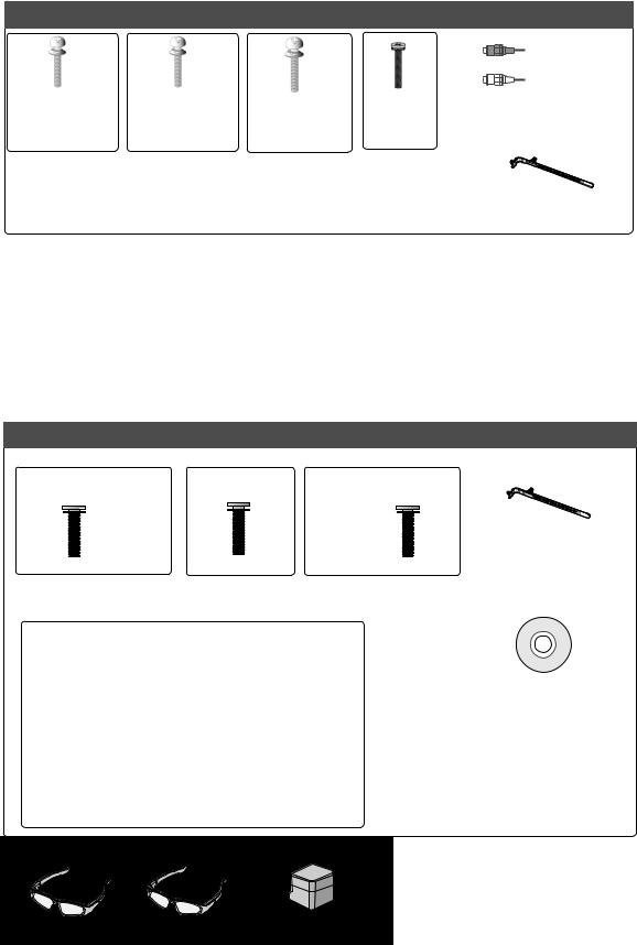
1-screw for stand fixing |
|||||||||||||||
|
|
|
|
|
|
|
|
|
||||||||||||||
|
|
|
|
|
|
|
|
|
((Refer to p. 19) |
21) |
||||||||||||
Nero MediaHome |
ENERGY AV MODE INPUT TV/ |
|
|
ENERGY |
AV MODE INPUT |
|
|
ENERGY AV MODE INPUT |
26/32LD3**,32/37/42LD4** |
|||||||||||||
|
|
Essentails 4 |
|
|
|
RAD |
|
|
|
|
TV/ |
|
|
|
|
TV/ |
(Only 26/32LD3**, 32/37/42LD4**, |
|||||
|
|
|
SAVING |
2 |
3 |
|
|
SAVING |
2 |
RAD |
|
|
SAVING |
2ABC |
RAD |
|||||||
|
|
|
1 |
|
|
1 |
3 |
|
|
1 |
3DEF |
32/42LD5**,32/37/42/LD6** |
|
|||||||||
|
|
|
|
|
|
|
|
|
|
|
|
|
|
|
|
|
|
|
|
32/42LD5**, 32/37/42LD6**, |
||
|
|
|
|
|
LIGHT |
|
4 |
5 |
6 |
|
|
4 |
5 |
6 |
|
|
4GHI |
5JKL |
6MNO |
32/37/42LD8**,32/42LE4***,32LE5***,32LE7***32LE5***) |
||
ENERGY AV MODE INPUT TV/ |
ENERGY AV MODE INPUT TV/ |
|
7 |
8 |
9 |
|
|
7 |
8 |
9 |
|
or |
7PQRS |
8TUV |
9WXYZ |
|||||||
SAVING |
|
RAD |
SAVING |
|
RAD |
|
LIST |
0 |
Q.VIEW |
|
or |
LIST 0 |
Q.VIEW |
|
LIST |
0 |
Q.VIEW |
|
|
|
||
1 |
2ABC |
3DEF |
1 |
2ABC |
3DEF |
|
|
MARK |
|
|
|
MARK |
|
|
|
MARK |
|
|
|
|
||
|
|
FAV |
|
|
|
FAV |
|
|
|
FAV |
|
|
|
|
||||||||
4GHI |
5JKL |
6MNO |
4GHI |
5JKL |
6MNO |
|
|
|
P |
P |
|
|
P |
P |
|
|
CHAR/NUM |
P |
|
|
|
|
|
|
RATIO |
A |
|
|
RATIO |
A |
|
|
RATIO |
A |
|
|
|
||||||||
|
|
|
EG |
|
|
|
EG |
|
|
DELETE |
P EG |
|
( |
|||||||||
7PQRS |
8TUV 9WXYZ |
7PQRS |
8TUV 9WXYZ |
|
|
MUTE |
|
|
|
|
MUTE |
|
|
|
|
MUTE |
|
|
||||
|
|
|
|
|
|
|
|
|
|
|
|
|
|
|
||||||||
LIST |
0 |
Q.VIEW |
LIST |
0 |
Q.VIEW |
|
MENU |
GUIDE |
Q.MENU |
|
|
MENU GUIDE |
Q.MENU |
|
|
MENU |
|
Q.MENU |
|
|||
|
MARK |
P or |
|
MARK |
|
|
|
|
|
|
|
|
|
|
|
|
|
|
|
|
32/37/42/47/55/60LE5***, |
|
|
FAV |
|
FAV |
|
|
|
|
|
|
|
OK |
|
|
|
|
|
|
|
||||
|
CHAR/NUM |
|
CHAR/NUM |
P |
|
OK |
|
|
|
|
|
|
|
|
OK |
|
|
|||||
|
3D |
A |
|
3D |
A |
|
|
|
|
|
|
|
|
|
|
|
|
|||||
|
DELETE |
P G |
|
DELETE |
P G |
|
|
|
|
|
|
|
|
|
|
|
|
|
|
|
||
|
E |
|
E |
|
|
|
|
|
|
|
|
|
|
|
|
|
|
|
||||
|
MUTE |
|
|
MUTE |
|
|
|
|
|
|
|
|
|
|
|
|
|
|
|
|
||
MENU |
|
Q.MENU |
MENU |
|
Q.MENU |
|
BACK |
INFO i |
EXIT |
|
|
BACK INFO i |
EXIT |
|
|
BACK |
GUIDE |
EXIT |
|
(Except for |
||
|
|
|
|
|
|
|
|
|
|
|
||||||||||||
|
|
|
|
|
|
|
|
|
|
|
|
|
|
|
|
|
|
|
|
|
32/37/42/47/55LE7***, |
|
|
OK |
|
|
OK |
|
|
|
|
SUBTITLE |
|
|
|
|
SUBTITLE |
|
|
|
|
SUBTITLE |
|
32/37/42/47/55/60LE5***, |
|
|
|
|
|
|
|
|
|
|
|
|
|
|
|
|
|
|
|
|
|
|
42/47/55LE8***, |
|
BACK |
GUIDE |
EXIT |
BACK |
GUIDE |
EXIT |
|
|
|
|
|
|
AD |
|
|
|
|
INFO i |
|
|
|
32/37/42/47/55LE7***, |
|
|
|
L/R SELECT |
|
|
L/R SELECT |
|
|
|
|
|
|
|
|
|
|
|
|
|
|
42/47/55LX6***,42/47/55LE8***)47/55LX9***) |
||
|
|
|
|
|
|
|
|
|
|
|
|
|
|
|
|
|
|
|
|
Power Cord |
||
INFO i |
RATIO |
|
INFO i |
RATIO |
|
|
|
|
|
|
|
|
|
|
|
|
||||||
|
|
|
|
|
|
|
|
|
|
|
|
|
|
|
|
|
||||||
Only 22LD3**22LD3** |
|
|
|
|
|
|
|
|
|
|
|
|
|
|
Only 26/32LD3**26/32LD3** |
|
||||||
|
|
|
|
|
|
|
|
|
|
|
|
|
|
|
|
|
|
|
|
x 8 |
|
|
|
|
|
|
|
|
|
|
|
|
|
|
|
|
|
|
|
|
|
|
(M4 X 20) |
|
|
CableCableHolderHolder |
Protection Cover |
|
BoltsProtectionfor stand assembly ProtectionCoverCover |
|||||||
|
|
|
Protection Cover |
|
||||||
((Refer to p. 18) (20)(Refer to p. 20) |
22) |
|
|
|
||||||
|
|
|
|
|
((Refer to p. 15) (17)(Refer to p. 20) 22) |
|||||
Only 32/37/4 |
/47LD 7LD4** |
|
|
Only |
|
|
|
|
||
|
|
32/42/46/52/60LD5** |
||||||||
|
2/37/42/4 |
|
|
|
|
|
|
|
|
|
|
|
|
|
|
|
(Except for 52/60LD5**) |
|
|
||
|
|
x 8 |
|
|
|
|
x 8 |
|
|
|
(M4 X 20) |
|
|
|
|
|
|
|
|||
Protection Cover |
|
|
M4X20 |
|
Protection Cover |
|||||
|
|
|
|
|
|
|||||
Bolts for stand assembly |
Protection Cover |
|
|
(M4 X 20) |
|
|
Protection Cover |
|||
|
|
|
|
( |
||||||
( |
|
|
||||||||
(Refer to p. 15) |
(Refer to p. 20) |
|
Bolts for stand assembly |
(Refer to p. 20) |
||||||
( 17) |
22) |
|
|
(Refer to p. 15) |
|
|
22) |
|||
|
|
|
|
|
|
( 17) |
||||
Only 22/26LE53**, |
|
|
|
|
|
|
|
|
||
22/26LE53** |
|
|
|
|
|
|
|
|
||
x 4 |
|
x 4 |
|
|
|
|
|
|
|
|
|
|
|
|
|
|
|
|
|
|
|
(M4x14) |
|
(M4x20) |
) |
|
|
|
AC/DC Adaptor |
|
4-Ring spacers |
|
|
(Only 26LE53 |
Cable Holder |
|
|
||||||
|
|
26LE53** |
((Refer to p. 21) |
Ring Spacers 4 |
||||||
|
|
|
|
Cable Holder |
(Only23)26LE53**) |
|||||
(Refer to p. 19) |
|
|
26LE53** |
|||||||
Bolts for stand assembly |
|
|
|
21) |
|
(Refer to p. 21) |
||||
((Refer to p. 16) |
(18) |
( 23) |
||||||||
4
Only 32/42/4732/37/42/47/55LE53****
x 4 |
x 4 |
|
x 4 |
|
x 4 |
(M4x22) |
(M4x24) |
|
(M4x26) |
|
(M4x16) |
(Only 32LE5332LE53**) |
(Only 42LE53**) |
|
|
||
|
(Only |
|
|||
|
37/42LE53** |
|
|
||
|
|
47/55LE 3** |
) |
|
|
|
|
|
E5 ** |
|
|
Bolts(for stand assembly (Refer to p. 16) 18)
Only 32/37/432/374 /42/47/55LD6**
x 8
(M4x20) |
Protection Cover |
|
Bolts for stand assembly |
|
|
Protection cover |
Nero MediaHome |
|
|
||
(Refer to p. 15) |
( |
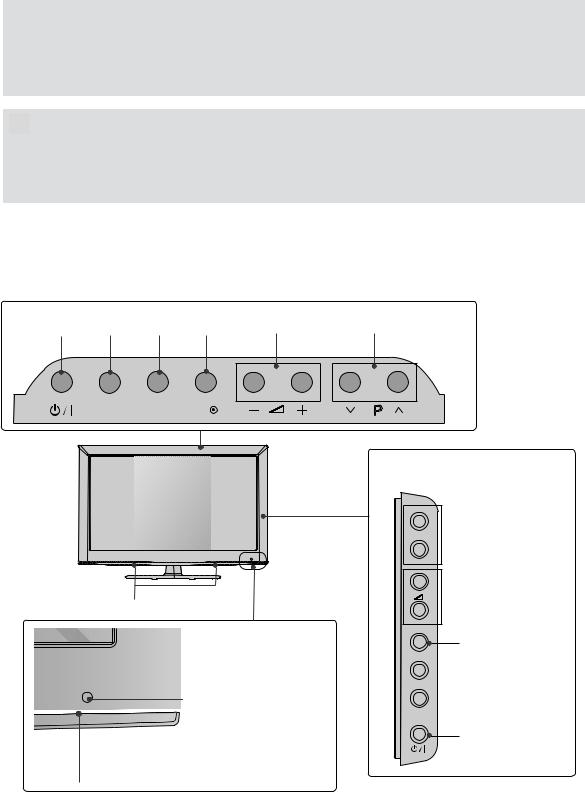
4 Essentials CD |
(Refer to p. 20) |
||
( 17 22) |
|
|


 x 2
x 2
ComponentComponentgender cable, AV genderAVcable
CableHolder
((Refer to p. 19) 21)
Only 32/37/432/374 /42/47/55/60LE55**,32/37/42/47/32/37/42/47/555LE7***,42/47/55LE8***,42/4755LX6***42/47/55LE8*** .47/55LX9***
|
32/37/42/47LE55** |
55LE55***, |
||||
|
(Only 32/37/42/47LE55**, |
|
|
|
|
|
|
|
|
(Only 55LE55 , |
|||
(Only 42/47/55LE842/47/55LE8***) |
|
|||||
|
32/37/42/47/LE7 ) |
|
|
) |
|
|
|
32/37/42/47LE7***42/47LX6*** |
|
|
|
55LE7***,55LX65** |
|
|
|
|
||||
|
|
|
|
|
|
|
x 8 |
x 8 |
x 4 |
x 4 |
(M4 x 16) |
(M4 x 20) |
(M4 x 24) (M4 x 16) |
|
(Bolts for stand assembly (Refer to p. 17) 19)
Cleansing Cloths(mitt) cleansing cloths(mitt)
( 32/37/42/47/55LE7***)
(Only 32/37/42/47/55LE7***)
Cable Holder
Cable Holder
47/55LX9500
(Refer to p. 19)
(21)
Nero MediaHome
4 Essentials CD
Slightly wipe stained spot on the exterior only with the cleansing cloths(mitt) for the product exterior if
thereis stain or fingerprint on surface of the exterior.
For cleaning front frame, please slowly wipe in one
direction after spraying water 1~2 times on cleansing
cloths. Please remove excessive moisture after cleaning. Excessive moisture may cause water stains on the frame.


 x 2
x 2
Component gender cable, AVComponentgender cableAV
(Only 42/47/55LX6 ) |
(Only |
|
( 42/47/55LX6***) |
(47/55LX9***) |
|
|
x 2 |
|
3D Glasses3 |
3D Glasses3 |
Stand RearCoverCover |
5

เกี่ยวกับพลังงานลดลงตามไปด้วย

ทำให้เกิดบาดแผลได้
Only 22/26/32LD3**
Only 22LD3** |
|
|
22LD3*** |
|
|
POWER INPUT MENu oK |
VOLUME |
PROGRAMME |
INPUT MENU OK |
P |
Only 26/32LD32LD3***
SPEAKER
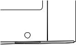
 Remote Control Sensor
Power/Standby Indicator
• Illuminates red in standby mode.
OPTION
• Illuminates blue when the TV is switched on.
P 
 PROGRAMME
 VOLUME
oK
OK
 MENu
MENu
MENU
 INPUT
INPUT
INPUT
POWER
6
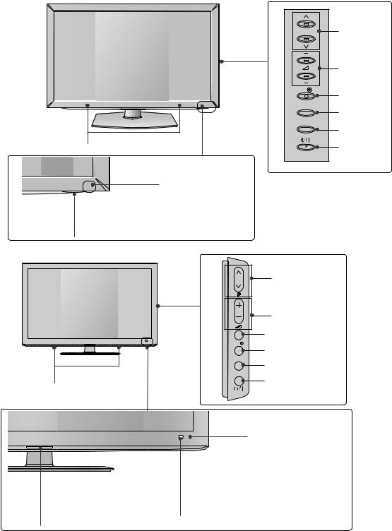
32/37/42/47LD4** |
|
|
P |
PROGRAMME |
|
|
VOLUME |
|
OK |
oK |
|
|
||
MENU |
MENu |
|
|
||
INPUT |
INPUT |
|
SPEAKER |
||
|
||
|
POWER |
|
|
Remote Control Sensor
Power/Standby Indicator
• Illuminates red in standby mode.
OPTION
• Illuminates blue when the TV is switched on.
Only 32/42/46/52/60LD5**32/46/52/60LD5**
|
PROGRAMME |
|
P |
|
VOLUME |
|
oK |
|
OK |
|
MENu |
|
MENU |
SPEAKER |
INPUT |
INPUT |
|
|
POWER |
|
Remote Control Sensor
Power/Standby Indicator |
IntelligentSensor |
|
Adjusts picture according to |
(Can be adjusted using the Power |
|
|
the surrounding conditions. |
Indicator in the oPtIon menu.) |
|
OPTION
7

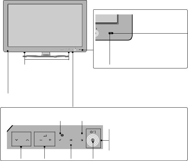
32/37/42/47/55LD6**
Speaker
Power/Standby Indicator
(Can be adjusted using the Power
Indicator in the oPtIon menu.)
OPTION
 remote Control Sensor
Intelligl ent Sensor
Adjusts picture according to
the surrounding conditions.
P  PROGRAMME
 VOLUME
OK
oK
MENU
 MENu
MENu
INPUT
 INPUT
INPUT

 POWER
POWER
Only 22/26LE53**22/26LE53**
Power/Standby Indicator
• Illuminates red in standby
mode.
• The LED is off while the TV
remains on.OPTION
Remote Control Sensor
SPEAKER
VOLUME MENu POWER
PROGRAMME oK INPUT
tTouchh Sensor
• You can use the desired button function by
touching.
8
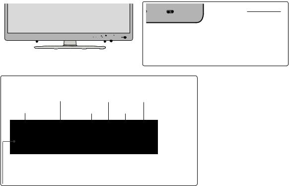
32/37/42/47/55/60LE5***, 32/37/42/47/55LE7***, 42/47/55LX6***
P |
OK |
MENU INPUT |
SPEAKER
Emitterter((Only 42/47/55LX642/47/55LX6***))
-It is the part equipped with the emitter 3Dexchanging signal with 3D glasses(3 ).
-Please be careful not to block 3D
the screen with objects or people
while watching a 3D Video.
Touch Sensor
• You can use the desired button function by touching.
|
OK |
INPUT |
|
P |
OK |
MENU INPUT |
|
PROGRAMME |
VOLUME |
MENU |
POWER |
Intelligent
 Sensor
Adjusts picture according to
the surrounding conditions.
Remote Control Sensor
Power/Standby Indicator
(Can be adjusted using the Power
Indicator in the OPTION menu.)
OPTION
9
Only 42/47/55LE8***42/47/55LE8***
|
IntelligentSensor |
|
Adjusts picture according to |
|
|
|
the surrounding conditions. |
P OK MENU INPUT |
|
|
|
|
Remote Control Sensor |
Speaker
tTouchSensor
• You can use the desired button function by touching.
VOLUME |
|
MENu |
POWER |
PROGRAMME |
oK |
INPUT |
|
P |
OK |
MENU INPUT |
|
Power/Standby Indicator
(Can be adjusted using the Power Indicator in the oPtIon
OPTION
menu.)
10
47/55LX9*** ly 47/55LX9***
PROGRAMME
VOLUME
OK
MENU
INPUT
POWER
SPEAKER
Emiittter ( 42/47/55LX6***)
It is the part equipped with the
the
- 3D
emitter exchanging signal with 3D
glasses3D. Please- be careful not to block 3D
the screen with objects or
people while watching a 3D
Video. Intelligent
 SensorSensor
Adjusts picture according to
the surrounding conditions.
Remote Control Sensor
Power/Standby Indicator (Can be adjusted using the Power Indicator
OPTIONin the OPTION menu.)
11
Only 22LD3**22LD3**
Only 26/32LD3**26/32LD3**
|
|
1 |
|
|
|
2 |
3 |
4 |
5 |
6 |
7 |

 /DVI IN
|
|
|
RS-232C IN |
|
|
|
|
|
(CONTROL & SERVICE) |
|
|||
AUDIO IN |
OPTICAL |
|
|
|
|
|
DIGITAL |
|
|
|
AVIN |
||
(RGB/DVI) AUDIO OUT |
VIDEO |
L(MONO) AUDIO |
R |
|||
|
||||||
RGB IN (PC)
VIDEO |
AUDIO |
ANTENNA / |
CABEL IN |
||
COMPONENT IN |
|
|
89
ONLY |
|
SERVICE |
10 |
|
H/P |
11 |
|
AC IN
|
1 |
|
|
|
|
2 |
3 |
5 |
6 |
|
7 |
|
|
OPTICAL |
|
RS-232C IN |
|
|
|
DIGITAL |
(CONTROL & SERVICE) |
|
|
|
|
AUDIO OUT |
|
|
|
|
RGB IN (PC) |
VIDEO |
AV IN 1 |
|
|
|
L/MONO |
|
|||
|
|
|
|
||
1 |
|
|
|
|
|
|
/DVI IN |
AUDIO IN |
|
|
ANTENNA / |
|
(RGB/DVI) |
VIDEO |
AUDIO |
||
|
|
CABLE IN |
|||
|
|
|
COMPONENT IN |
|
|
|
|
4 |
8 |
|
9 |
 SERVICE ONLY
H/P IN 2

AV IN2
12
2
11
7
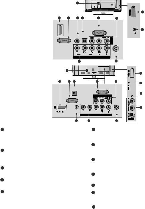
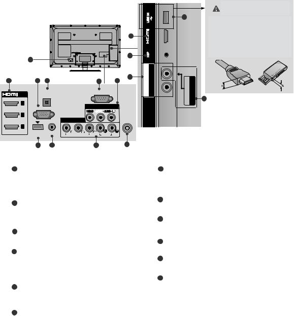
1 |
Power cord Socket |
6 |
rS-232c In (control & ServIce) Port |
||
|
This TV operates on an AC power. The volt- |
|
Connect to the RS- |
232C |
port on a PC. |
|
|
|
|
( ) |
|
|
age is indicated on the Specifications page. |
|
RS- |
||
|
|
This port is used for Service or Hotel mode. |
|||
|
|
|
|||
|
Never attempt to operate the TV on DC |
|
, Hotel |
||
|
|
|
|
||
|
power. |
7 |
audio/video Input |
|
|
|
|
|
|
||
2 |
hdMI/dvI In Input |
|
Connect audio/video output from an external |
||
|
device to these jacks. |
|
|||
|
Connect an HDMI signal to HDMI IN. Or DVI |
|
(AV) |
||
|
(VIDEO) signal to HDMI/DVI port with DVIHDMIto |
8 |
component Input |
|
|
|
HDMI cable. |
|
|
||
|
DVI ( HDMI ) |
|
|
||
|
rgB In Input |
|
Connect a component video/audio device to |
||
3 |
|
these jacks. |
|||
|
Connect the output from a PC. |
9 |
antenna / cable Input |
|
|
|
RGB |
|
|||
|
|
Connect antenna or cable to this jack. |
|||
4 |
rgB/dvI audio Input |
|
|||
|
( , |
||||
|
Connect the audio from a PC or DTV. |
10 |
|
|
|
|
RGB/DVI ServIce only Port |
|
|||
5 |
oPtIcal dIgItal audIo out |
11 |
headphone Socket |
|
|
|
Connect digital audio to various types of |
|
Plug the headphone into the headphone |
||
|
|
||||
|
equipment. |
|
socket. |
|
|
|
|
|
|
|
|
|
|
|
|||
|
Connect to a Digital Audio Component. |
|
|
|
|
|
Optical Audio |
12 |
uSB Input |
|
|
|
Use an Optical audio cable. |
|
|
||
Connect USB storage device to this jack.
USB
12

Only 32/37/42/47LD4**
32/37/42/47LD4**
|
|
1 |
|
|
|
2 |
4 |
5 |
7 |
|
8 |
|
|
OPTICAL |
|
RS-232C IN |
|
|
|
DIGITAL |
(CONTROL & SERVICE) |
|
|
|
|
AUDIO OUT |
|
|
|
|
RGB IN (PC) |
VIDEO |
AV IN 1 |
|
|
|
L/MONO |
|
|||
|
|
|
|
||
1 |
|
|
|
|
|
|
/DVI IN |
AUDIO IN |
|
|
ANTENNA / |
|
(RGB/DVI) |
VIDEO |
AUDIO |
||
|
|
CABLE IN |
|||
|
|
|
COMPONENT IN |
|
|
|
|
6 |
9 |
|
10 |
H/P IN 2

AV IN2
11
2
12
8
Only 32/42/46/52/60LD55*
|
1 |
|
|
|
|
|
|
2 |
3 |
4 |
5 |
6 |
|
7 |
8 |
|
|
|
|
|
RS-232C IN |
|
|
|
|
|
OPTICAL |
|
(CONTROL & SERVICE) |
|
|
|
|
|
|
|
|
|
|
|
|
|
DIGITAL |
|
|
|
|
|
|
|
AUDIO OUT |
|
|
|
|
|
|
|
|
|
AV IN1 |
|
|
|
|
|
|
VIDEO |
L/MONO AUDIO |
R |
|
|
|
RGB IN (PC) |
|
|
2 |
|
|
2 |
|
|
|
|
|
|
|
|
|
|
|
|
|
|
|
1 |
|
|
|
|
|
1 |
|
/DVI IN |
WIRELESS |
AUDIO IN |
VIDEO |
AUDIO |
ANTENNA / |
|
COMPONENT IN |
||||||
CONTROL |
(RGB/DVI) |
CABLE IN |
||||
|
|
|
9 |
|
10 |
|
H/P IN3

AVIN2
11
2
12
8
1 |
Power cord Socket |
7 |
rS-232c In (control & ServIce) Port |
||
|
This TV operates on an AC power. The volt- |
|
Connect to the RS- |
port on a PC. |
|
|
|
|
RS232C- |
( ) |
|
|
age is indicated on the Specifications page. |
|
This port is used for Service or Hotel mode. |
||
|
|
|
|||
|
Never attempt to operate the TV on DC |
|
, Hotel |
||
|
power. |
|
|
||
|
|
8 |
audio/video Input |
|
|
2 |
hdMI/dvI In Input |
|
Connect audio/video output from an external |
||
|
Connect an HDMI signal to HDMI IN. Or DVI |
|
device to these jacks. |
(AV) |
|
|
(VIDEO) signal to HDMI/DVI port with DVIHDMIto |
|
|||
|
HDMI cable. |
|
|
|
|
|
DVI ( HDMI )9 |
|
|
||
|
|
|
component Input |
|
|
3 |
wIreleSS control |
|
Connect a component video/audio device to |
||
|
Connect the Wireless Dongle to the TV to |
|
these jacks. |
||
|
control the external input devices connected 10Media Box |
|
|
||
|
to Media Box wirelessly. |
|
antenna / cable Input |
|
|
|
( )Connect antenna or cable to this jack. |
||||
|
|
|
( , |
||
4 rgB In Input
Connect the output from a PC.RGB
11 uSB Input
Connect USB storage device to this jack.
USB
5 oPtIcal dIgItal audIo out |
12 |
headphone Socket |
Connect digital audio to various types of |
|
Plug the headphone into the headphone |
equipment. |
socket. |
|
Optical Audio
Connect to a Digital Audio Component.
Use an Optical audio cable.
6rgB/dvI audio Input
Connect the audio from a PC or DTV. RGB/DVI
13

Only 32/42/52LD52LD56*,32/32/37/42/47/55LD67/42/47/55LD6*** Only 22/26LE53**22/26LE53**
1
|
|
|
|
|
or |
|
|
|
|
IN 2 |
|
|
|
|
|
|
|
|
|
|
USB |
|
1 |
|
|
|
|
|
|
|
|
IN 1 |
|
|
|
|
|
|
|
|
|
USB |
|
|
|
|
|
|
|
|
|
|
|
|
|
|
|
|
|
|
|
|
|
|
puGZ |
2 |
3 |
4 |
5 |
6 |
7 |
|
|
8 |
|
|
|
|
|
|
|
RS-232C IN |
|
|
|
|
|
|
|
|
RGB IN (PC) |
(CONTROL & SERVICE) |
|
|
H/P |
|||
LAN |
/DVI IN |
|
|
|
|
|
1 |
|
||
|
|
|
|
|
AVIN |
|
|
|||
|
RGB/DVI |
OPTICALDIGITAL |
VIDEO L(MONO) AUDIO |
R |
|
|
||||
|
|
|
|
|
||||||
|
2 |
|
|
|
|
|
|
|
|
|
|
|
AUDIO IN AUDIO OUT |
|
|
1 |
COMPONENT |
|
|
||
|
1 |
|
|
|
|
|
|
|
||
WIRELESS |
|
|
|
|
|
2 |
|
|
|
|
|
|
|
|
|
|
|
|
|
|
|
CONTROL |
|
|
|
|
|
|
|
|
|
|
|
|
|
|
VIDEO |
AUDIO |
|
|
IN |
ANTENNA / |
h}GpuY |
|
|
|
|
|
|
|
|
|
CABLE IN |
|
9 |
|
|
|
10 |
|
|
|
|
11 |
|
12
12
3
13
8
14
DC-IN
|
12 |
|
|
2 |
3 |
|
|
IN |
H/P |
13 |
H/P |
Only 22LE53**22LE** Only 26LE53**26LE53**
3 |
|
4 |
6 |
7 |
8 |
IN |
1 |
2 |
|
|
|
/DVI |
|
|
|
||
(DVI) |
|
|
RS-232C IN |
|
|
|
|
|
|
(CONTROL & SERVICE) |
|
|
|
AUDIO IN |
OPTICALDIGITAL |
AV IN |
|
|
|
(RGB/DVI) |
AUDIO OUT |
VIDEO L(MONO) |
|
|
RGB IN (PC) |
|
|
|
|
|
|
|
VIDEO |
AUDIO |
ANTENNA / |
|
|
|
COMPONENT IN |
CABLE IN |
|
|
|
|
|
||
|
5 |
10 |
|
|
11 |
|
|
|
|
||
1
2
3
Power cord Socket |
7 |
rS-232c In (control & ServIce) Port |
|
This TV operates on an AC power. The volt- |
|
Connect to the RS-232Cport on a PC. |
|
age is indicated on the Specifications page. |
|
RS- |
( ) |
|
|
This port is used for Service or Hotel mode. |
|
Never attempt to operate the TV on DC |
|
, Hotel |
|
|
|
||
power. |
8 |
audio/video Input |
|
|
|
||
lan |
|
Connect audio/video output from an external |
|
|
device to these jacks. |
|
|
Network connectionLAN for Weather info, Photo |
(AV) |
||
|
|
||
Album, Movie Online, etc. |
9 |
wIreleSS control |
|
|
|
||
Also used for video, photo and music files on |
|
Connect the Wireless Dongle to the TV to |
|
|
|
||
a local network. |
|
control the external input devices connected |
|
(local) |
|
to Media Box wirelessly. |
|
hdMI/dvI In Input |
|
( |
|
10 |
component Input |
|
|
Connect an HDMI signal to HDMI IN. Or DVI |
|
||
(VIDEO) signal to HDMI/DVI port with DVIHDMIto |
|
Connect a component video/audio device to |
|
HDMI cable. |
|
these jacks. |
|
DVI ( HDMI ) |
|
||
4 |
rgB/dvI audio Input |
11 |
antenna / cable Input |
|
|
Connect the audio from a PC or DTV. |
|
Connect antenna or cable to this jack. |
|
|
RGB/DVI ( , |
|||
5 |
rgB In Input |
12 |
uSB Input |
|
|
Connect the output from a PC. |
|
Connect USB storage device to this jack. |
|
|
RGB |
USB |
||
6 |
oPtIcal dIgItal audIo out |
13 |
headphone Socket |
|
|
Connect digital audio to various types of |
|
Plug the headphone into the headphone |
|
|
|
socket. |
||
|
equipment. |
|
|
|
|
|
|
|
|
|
Connect to a Digital Audio Component. |
|
dc adaPter Port |
|
|
Optical Audio |
14 |
||
|
Use an Optical audio cable. |
|
|
|
Connect to the power cord socket.
DC Adapter
14
■Image shown may differ from your TV.
|
|
|
|
Only |
|
11 |
CAUTION |
32/37/42/47/55LE53** |
IN |
|
|
|
USB |
|
►Use a product with the follow- |
|
|
|
|
|
|
|
ing thicknessHDMIfor optimal(HDMIconIN -4) |
2
12
1
H/P
nection to HDMIUSBcable(only
HDMI IN104) / .USB device. *A  10 mm
10 mm
2 |
|
3 |
4 |
|
|
9 |
|
|
5 |
6 |
|||
|
/DVI IN |
|
OPTICAL |
|
RS-232C IN |
|
|
|
DIGITAL |
(CONTROL & SERVICE) |
|||
|
|
|
AUDIO OUT |
|
|
|
|
3 |
|
|
|
AV IN 1 |
|
|
|
RGB IN (PC) |
|
|
||
|
|
VIDEO |
L(MONO) AUDIO |
R |
||
|
2 |
|
|
|||
|
|
|
|
|
ANTENNA / |
|
|
|
|
|
COMPONENT IN1 |
|
|
|
|
|
AUDIO IN |
|
CABLE IN |
|
|
1 |
|
|
|
|
|
|
(DVI) |
WIRELESS (RGB/DVI) |
|
AUDIO |
|
|
|
|
VIDEO |
|
|||
|
|
CONTROL |
|
|||
|
|
7 |
8 |
|
9 |
10 |
COMPONENT IN2 Y PB PR / AUDIO
IN2 |
/AUDIO |
AV |
VIDEO |
6
1 |
Power Cord Socket |
|
7 |
WIRELESS Control |
|
This TV operates on an AC power. The volt- |
|
Connect the Wireless Dongle to the TV to |
|
|
age is indicated on the Specifications page. |
|
control the external input devices connected |
|
|
|
|
|
|
|
|
|
|
|
|
Never attempt to operate the TV on DC |
|
|
to Media Box wirelessly. |
|
( |
|||
|
power. |
|
|
|
|
|
|
8 |
RGB/DVI Audio Input |
2 |
HDMI/DVI IN Input |
|
||
|
|
Connect the audio from a PC or DTV. |
||
|
Connect an HDMI signal to HDMI IN. Or DVI |
|
RGB/DVI |
|
|
|
to |
|
|
|
(VIDEO) signal to HDMI/DVI port with DVIHDMI |
Component Input |
||
|
HDMI cable. |
|
9 |
|
|
( HDMI ) |
Connect a component video/audio device to |
||
3 |
RGB IN Input |
|
|
these jacks. |
|
|
|
||
|
Connect the output from a PC. |
|
10 |
|
|
|
|
||
|
AntennaRGB/ Cable Input |
|||
|
|
|
Connect antenna or cable to this jack. |
|
OPTICAL DIGITAL AUDIO OUT |
|
|
||
4 |
|
|
( , |
|
|
Connect digital audio to various types of |
|
|
|
|
11 USB Input |
|||
|
equipment. |
|
|
Connect USB storage device to this jack. |
|
|
|
|
|
|
Connect to a Digital Audio Component. |
|
|
USB |
|
Optical Audio |
|
|
Headphone Socket |
|
Use an Optical audio cable. |
|
12 |
|
|
RS-232C IN (CONTROL & SERVICE) PORT |
|
Plug the headphone into the headphone |
|
5 |
|
socket. |
||
|
Connect to the RS-232C port on a PC. |
|
|
|
|
RS-232C ( ) |
|
|
|
This port is used for Service or Hotel mode.
, Hotel
6Audio/Video Input
Connect audio/video output from an external
device to these jacks. (AV)
15
 Loading...