


OWNER’S MANUAL
LED TV*
* LG LED TV applies LCD screen with LED backlights.
Click! User Guide
Please read this manual carefully before operating your set and retain it for future reference.
LB63** LB68** LB72** LB87** LB65** LB69** LB73**
LB67** LB70** LB86**
*MFL68027020* |
www.lg.com |
P/NO : MFL68027020(1405-REV02)
Printed in Korea

A-2 TABLE OF CONTENTS
TABLE OF CONTENTS
A-3 SETTING UP THE TV
A-3 Attaching the stand
A-8 Attaching the Sound Bar Supporter A-10 Tidying cables
A-12 MAKING CONNECTIONS
A-12 Antenna connection A-12 Satellite dish connection A-13 HDMI connection
A-14 - ARC (Audio Return Channel) A-14 DVI to HDMI connection
A-16 Component connection A-17 Composite connection A-18 MHL connection
A-19 Audio connection
A-19 - Digital optical audio connection A-20 USB connection
A-21 CI module connection A-22 Headphone connection A-23 Euro Scart connection
language list
English
Italiano
B-1 SPECIFICATIONS
COMMON
LANGUAGE
COMMON
SETTING UP THE TV |
A-3 |
|
|
SETTING UP THE TV
70LB65**-ZA, LB67**, LB68**, LB69**, LB73**-ZA
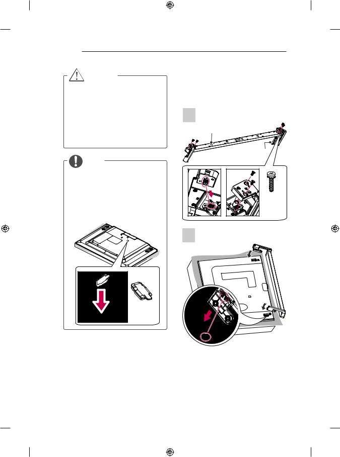
1
Image shown may differ from your TV. |
Stand Body |
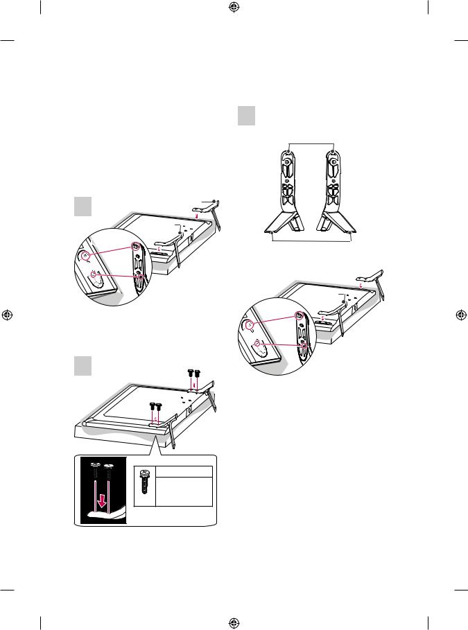
Attaching the stand
LB63**-ZA, 32/39/42/47/50/55LB65**-ZA
1 |
A stand base |
|
|
|
B stand base |
 1
1

 2
2
1Attach the stand to the TV using the upper mounting hole on the back of the TV.
2Attach the stand to the TV using the lower connection on the back of the TV.
2
Stand Base
A stand Assy 
B stand Assy
 1
1


 2
2
1Attach the stand to the TV using the upper mounting hole on the back of the TV.
2Attach the stand to the TV using the lower connection on the back of the TV.
|
M4 x L14 |
|
M4 x L20 |
|
(Only 32LB65**- |
4EA |
ZA) |
A-4 SETTING UP THE TV
2 |
2 |
|
4EA M4 x L14
LB63**-ZL, LB65**-ZK
1
A stand base 

B stand base
 1
1

 2
2
1Attach the stand to the TV using the upper mounting hole on the back of the TV.
2Attach the stand to the TV using the lower connection on the back of the TV.
|
M4 x L14 |
|
|
M4 x L20 |
|
|
(Only |
|
4EA |
32LB65**- |
|
ZK) |
||
|
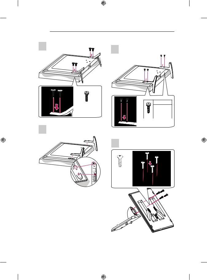
32/39LB65**-ZE/ZN
1
4EA M4 x L20
Stand Body
Stand Base
2
3
2EA M4 x L20
SETTING UP THE TV |
A-5 |
42/47/50/55/60LB65**-ZE/ZN
1
4EA M4 x L20
Stand Body
Stand Base
2

A-6 SETTING UP THE TV
3
4EA M4 x L14
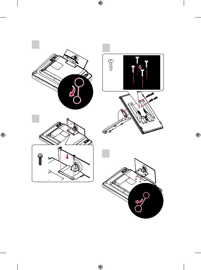
LB70**, LB72**, LB73**-ZD/ZE
1
3
 1
1


 2
2
1Attach the stand to the TV using the upper mounting hole on the back of the TV.
2Attach the stand to the TV using the lower connection on the back of the TV.
4
Stand Front
B Stand
Supporter
2 |
A Stand
Supporter
4EA M4 x L10
4EA M4 x L14
SETTING UP THE TV |
A-7 |
|
|
3
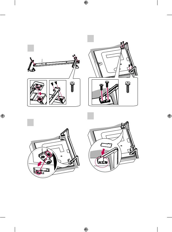
LB86**, LB87**
1
Sound Bar
Stand Assy Right 
 Stand Assy Left
4EA |
4EA |
M4 x L14 |
M4 x L14 |
4
2
Screw Cover 

A-8 SETTING UP THE TV
CAUTION
yy When attaching the stand to the TV set, place the screen facing down on a cushioned table or flat surface to protect the screen from scratches.
yy Make sure that the screws are inserted correctly and fastened securely. (If they are not fastened securely enough, the TV may tilt forward after being installed.)
Do not use too much force and over tighten the screws; otherwise screw may be damaged and not tighten correctly.
NOTE
yy Remove the stand before installing the TV on a wall mount by performing the stand attachment in reverse.
yy The Screw Cover will protect the opening from accumulating dust and dirty.
yy The Rubber will protect the opening from accumulating dust and dirt. When installing the wall mounting bracket, use the Rubber. (Only LB65**-ZE/ZN)
Attaching the Sound Bar
Supporter
(In case of mounting on a wall) LB86**, LB87**
1
Sound Bar
Sound Bar Supporter Right
 Sound Bar Supporter Left
4EA M4 x L14
2
Rubber
SETTING UP THE TV |
A-9 |
|
|
3
4EA M4 x L14
4
Screw Cover 
CAUTION
yy When attaching the sound bar supporter to the TV set, place the screen facing down on a cushioned table or flat surface to protect the screen from scratches.
yy Make sure that the screws are inserted correctly and fastened securely. (If they are not fastened securely enough, the TV may tilt forward after being installed.)
Do not use too much force and over tighten the screws; otherwise screw may be damaged and not tighten correctly.
yy The sound bar supporter only uses for wall mounting.
yy After assembling the Sound Bar Wall Mount Brackets, do not adjust the angle of the TV while holding the Sound Bar or hanging onto the Sound Bar.
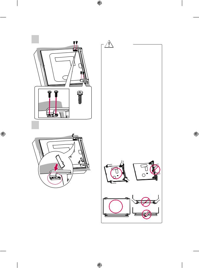
yy When lifting the product, or moving it, make sure that two or more people safely lift it and set it upright on a flat surface. When there are two people, one person should stand on the right side of the product and the other person should stand on the left side to lift it. When moving the product, hold the top and bottom corners.
yy When lifting the product, or moving it, do not hold the Sound Bar. If you hold the Sound Bar when lifting the product, or moving it, the Sound Bar may be damaged.
<When lifting the product>
<When moving the product>
A-10 SETTING UP THE TV
NOTE
yy Remove the sound bar supporter before installing the stand by performing the sound bar supporter attachment in reverse.
yy The Screw Cover will protect the opening from accumulating dust and dirty.
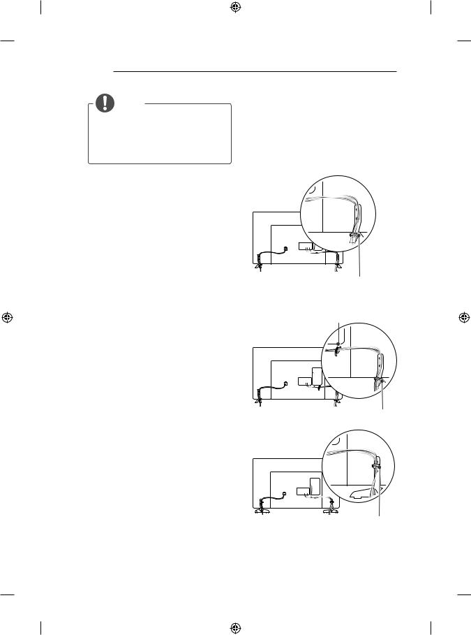
Tidying cables
Image shown may differ from your TV.
1Gather and bind the cables with the Cable Holder. (Depending on model)
2Fix the Cable Management firmly to the TV.
(Only 32LB65**-ZA)
Cable Management
(Only LB63**-ZA, 39/42/47/50/55/60LB65**-ZA, LB67**, LB68**, LB69**, LB73**-ZA)
Cable Holder
Cable Management
(Only 32LB65**-ZK)
Cable Management
|
SETTING UP THE TV A-11 |
(Only LB63**-ZL, 39/42/47/50/55/60/70LB65**- |
(Only LB70**, LB72**, LB73**-ZD/ZE) |
ZK/ZL) |
|
Cable Holder |
Cable Holder |
|
Cable Management
(Only LB65**-ZE/ZN)
Cable Holder
(Only 70LB65**)
Cable Holder
Cable Management
(Only LB86**, LB87**)
Cable Holder 
Cable Management
CAUTION
yy Do not move the TV by holding the cable holders, as the cable holders may break, and injuries and damage to the TV may occur.
Cable Management
A-12 MAKING CONNECTIONS
MAKING CONNECTIONS
This section on MAKING CONNECTIONS mainly uses diagrams for the LB67** models.
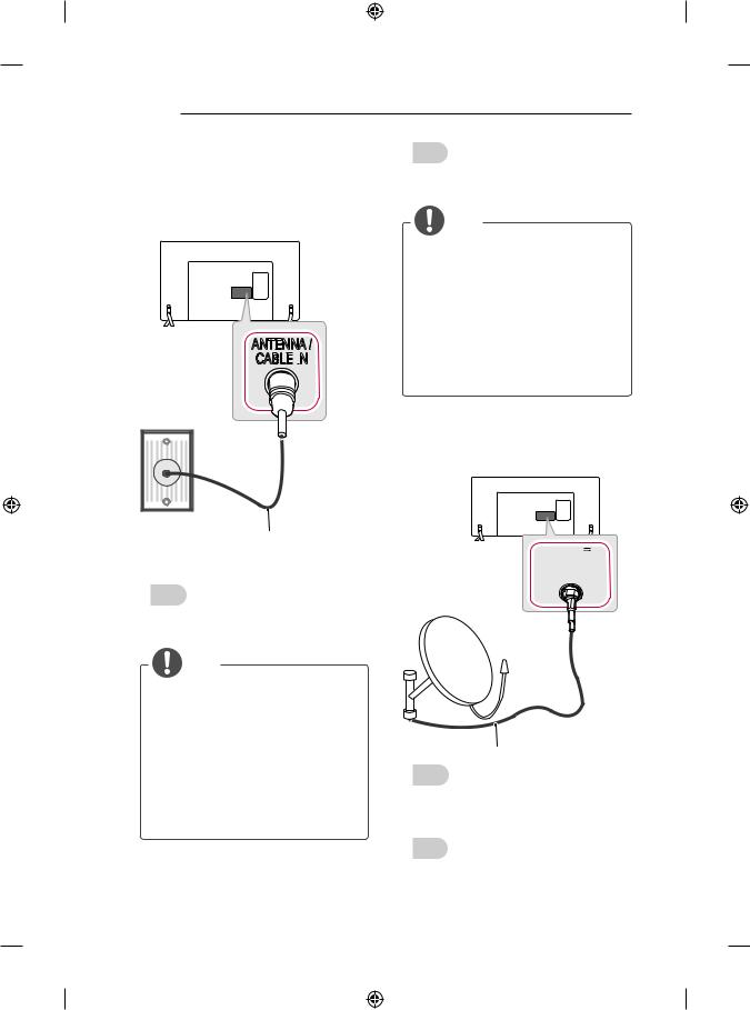
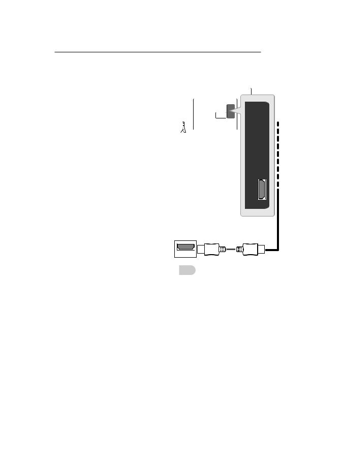
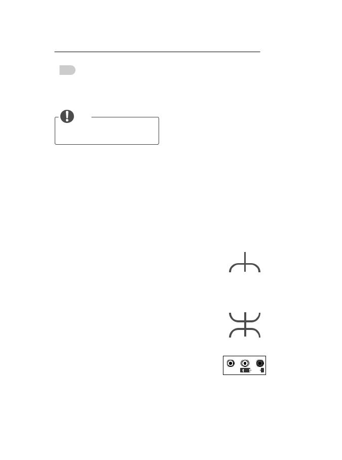
Antenna connection
ANTENNA /
CABLE IN
IN
Italiano
Collegare il televisore all’antenna centralizzata con un cavo RF (75 Ω).
NOTA
yy Utilizzare uno sdoppiatore del segnale per usare più di 2 televisori.
yy Se la qualità dell’immagine è scarsa, installare correttamente un amplificatore del segnale per migliorarla.
yy Se la qualità dell’immagine è scarsa con un’antenna collegata, provare a riallineare l’antenna nella direzione corretta.
yy Il cavo e il convertitore dell’antenna non sono in dotazione.
yy Audio DTV supportato: MPEG, Dolby Digital, Dolby Digital Plus, HE-AAC
Satellite dish connection
(Only satellite models)
(*Not Provided)
13/18V
700mA Max
English
Connect the TV to a wall antenna socket with an
RF cable (75 Ω).
NOTE
yy Use a signal splitter to use more than 2 TVs.
yy If the image quality is poor, install a signal amplifier properly to improve the image quality.
yy If the image quality is poor with an antenna connected, try to realign the antenna in the correct direction.
yy An antenna cable and converter are not supplied.
yy Supported DTV Audio: MPEG, Dolby Digital, Dolby Digital Plus, HE-AAC
LNB
Satellite IN
(*Not Provided)
English
Connect the TV to a satellite dish to a satellite socket with a satellite RF cable (75 Ω).
Italiano
Collegare la TV a un’antenna satellitare e a una presa satellitare con un cavo RF satellitare (75 Ω).
MAKING CONNECTIONS A-13
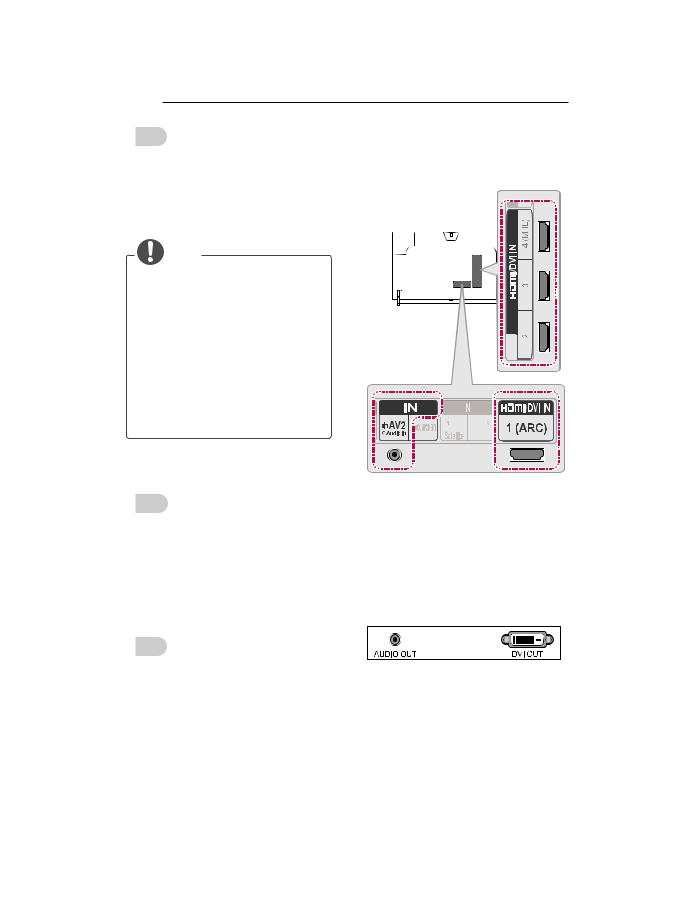
HDMI connection |
|
|
|
|
(Only LB63**, LB65**, LB67**, LB68**, LB69**, |
|||
|
|
|
|
|
|
|||
|
|
|
|
|
|
LB70**, LB72**, LB73**) |
||
(Only LB86**, LB87**) |
|
|
|
|
|
|
|
|
|
|
|
|
|
|
|
|
|
|
|
|
|
|
|
|
|
|
|
|
|
|
|
|
|
|
|
|
|
|
|
|
|
|
|
|
|
|
|
|
|
|
|
|
|
|
|
|
|
|
|
|
|
|
DVD/ Blu-Ray / HD Cable Box / HD STB / PC
 (*Not Provided)
(*Not Provided)
English
Transmits the digital video and audio signals from an external device to the TV. Connect the external device and the TV with the HDMI cable as shown.
Choose any HDMI input port to connect. It does not matter which port you use.
DVD/ Blu-Ray / HD Cable |
NOTE |
Box / HD STB / PC |
yy It is recommended to use the TV with the HDMI connection for the best image quality.
yy Use the latest High Speed HDMI™ Cable with CEC (Customer Electronics Control) function.
yy High Speed HDMI™ Cables are tested to carry an HD signal up to 1080p and higher.
yy Supported HDMI Audio format : Dolby Digital, DTS, PCM (Up to 192 KHz, 32KH z/44.1KHz/48KHz/88KHz/96KHz/176KHz /192KHz)
A-14 MAKING CONNECTIONS
Italiano
Il segnale digitale audio e video viene trasmesso da un dispositivo esterno al televisore. Collegare il dispositivo esterno e il televisore mediante il cavo HDMI come mostrato nell’illustrazione di seguito.
Scegliere una porta di ingresso HDMI per il collegamento. La scelta della porta è libera.
NOTA
yy Si consiglia di utilizzare il televisore con il collegamento HDMI per ottenere la migliore qualità delle immagini.
yy Utilizzare un cavo HDMI™ ad alta velocità dotato dei requisiti più recenti con funzione CEC (Customer Electronics Control).
yy I cavi HDMI™ ad alta velocità sono testati per trasmettere un segnale HD fino a 1080p e superiore.
yy Formato audio HDMI supportato: Dolby Digital, DTS, PCM (fino a 192 KHz,
32 KHz/44,1 KHz/48 KHz/88 KHz/96 KHz/176 KHz/192 KHz)
ARC (Audio Return Channel)
English
yyAn external audio device that supports SIMPLINK and ARC must be connected using HDMI IN 1 (ARC) or HDMI/DVI IN 1 (ARC) port.
yyWhen connected with a high-speed HDMI cable, the external audio device that supports ARC outputs optical SPDIF without additional optical audio cable and supports the SIMPLINK function.
Italiano
yyUn dispositivo audio esterno che supporta SIMPLINK e ARC deve essere collegato tramite la porta HDMI IN 1 (ARC) o HDMI/ DVI IN 1 (ARC).
yySe si effettua il collegamento con un cavo HDMI ad alta velocità, il dispositivo audio esterno che supporta ARC trasmette il segnale SPDIF senza il cavo ottico aggiuntivo e supporta la funzione SIMPLINK.
DVI to HDMI connection
(Only LB86**, LB87**)
 (*Not Provided)
DVD/ Blu-Ray / HD Cable Box / HD STB / PC
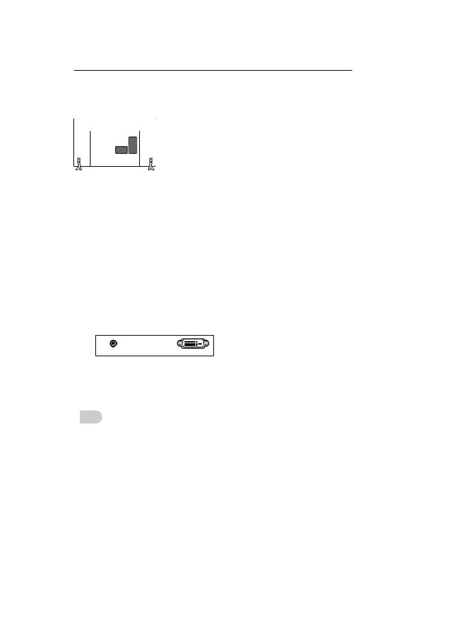
(Only LB63**, LB65**, LB67**, LB68**, LB69**,
LB70**, LB72**, LB73**)
|
|
|
|
|
|
|
|
|
|
|
|
|
|
|
|
|
|
|
|
|
|
|
|
|
|
|
|
|
|
|
|
|
|
|
|
|
|
|
|
|
|
|
|
|
| <![if ! IE]> <![endif]>WHITE |
<![if ! IE]> <![endif]>RED |
|
||
|
||||
 (*Not Provided)
MAKING CONNECTIONS A-15
Italiano
Il segnale digitale video viene trasmesso da un dispositivo esterno al televisore. Collegare il dispositivo esterno e il televisore mediante il
cavo DVI-HDMI come mostrato nell’illustrazione di seguito. Per trasmettere un segnale audio, collegare un cavo audio.
Scegliere una porta di ingresso HDMI per il collegamento. La scelta della porta è libera.
NOTA
yy A seconda della scheda grafica in uso, la modalità DOS potrebbe non funzionare se si utilizza un cavo da HDMI a DVI.
yy Quando si utilizza il cavo HDMI/DVI, è supportata solo l’interfaccia Single link.
|
|
|
|
|
|
|
|
|
|
|
|
AUDIO OUT |
DVI OUT |
||||
DVD / Blu-Ray / HD Cable Box / HD STB / PC
English
Transmits the digital video signal from an external device to the TV. Connect the external device and the TV with the DVI-HDMI cable as shown. To transmit an audio signal, connect an audio cable. Choose any HDMI input port to connect. It does not matter which port you use.
NOTE
yy Depending on the graphics card, DOS mode may not work if a HDMI to DVI Cable is in use.
yy When using the HDMI/DVI cable, only Single link is supported.
A-16 MAKING CONNECTIONS
Component connection
(Only LB86**, LB87**)
IN
AV2 COMPONENT
VIDEO 
 PR P Y
|
|
|
|
GREEN |
|
|
|
|
|
YELLOW |
|
|||
(Use the composite |
|
(Use the |
||
gender cable |
|
component gender |
||
provided.) |
|
cable provided.) |
||
| <![if ! IE]> <![endif]>YELLOW |
<![if ! IE]> <![endif]>WHITE |
<![if ! IE]> <![endif]>RED |
<![if ! IE]> <![endif]>RED |
<![if ! IE]> <![endif]>BLUE |
<![if ! IE]> <![endif]>GREEN |
| <![if ! IE]> <![endif]>WHITE |
<![if ! IE]> <![endif]>RED |
<![if ! IE]> <![endif]>RED |
<![if ! IE]> <![endif]>BLUE |
<![if ! IE]> <![endif]>GREEN |
(*Not Provided)
| <![if ! IE]> <![endif]>WHITE |
<![if ! IE]> <![endif]>RED |
<![if ! IE]> <![endif]>RED |
<![if ! IE]> <![endif]>BLUE |
<![if ! IE]> <![endif]>GREEN |
L |
R |
|
|
|
AUDIO |
|
VIDEO |
|
|
DVD / Blu-Ray / HD Cable Box
(Only LB63**, LB65**, LB67**, LB68**, LB69**,
LB70**, LB72**, LB73**)
| <![if ! IE]> <![endif]>GREEN |
<![if ! IE]> <![endif]>BLUE |
<![if ! IE]> <![endif]>RED |
<![if ! IE]> <![endif]>WHITE |
<![if ! IE]> <![endif]>RED |
|
|
(*Not |
|
|
|
Provided) |
|
|
|
| <![if ! IE]> <![endif]>GREEN |
<![if ! IE]> <![endif]>BLUE |
<![if ! IE]> <![endif]>RED |
<![if ! IE]> <![endif]>WHITE |
<![if ! IE]> <![endif]>RED |
|
|
L |
|
R |
VIDEO |
|
AUDIO |
|
|
DVD / Blu-Ray / HD Cable Box
English
Transmits analog video and audio signals from an external device to the TV. Connect the external device and the TV with a component cable as shown.
 NOTE
NOTE
yy If cables are not installed correctly, it could cause this image to display in black and white or with distorted colours.
MAKING CONNECTIONS A-17
Italiano
Il segnale audio e video analogico viene trasmesso da un dispositivo esterno al televisore. Collegare il dispositivo esterno al televisore usando un cavo component come mostrato nella figura di seguito.
NOTA
yy L’errato collegamento dei cavi può far sì che le immagini vengano visualizzate in bianco e nero o con colori distorti.
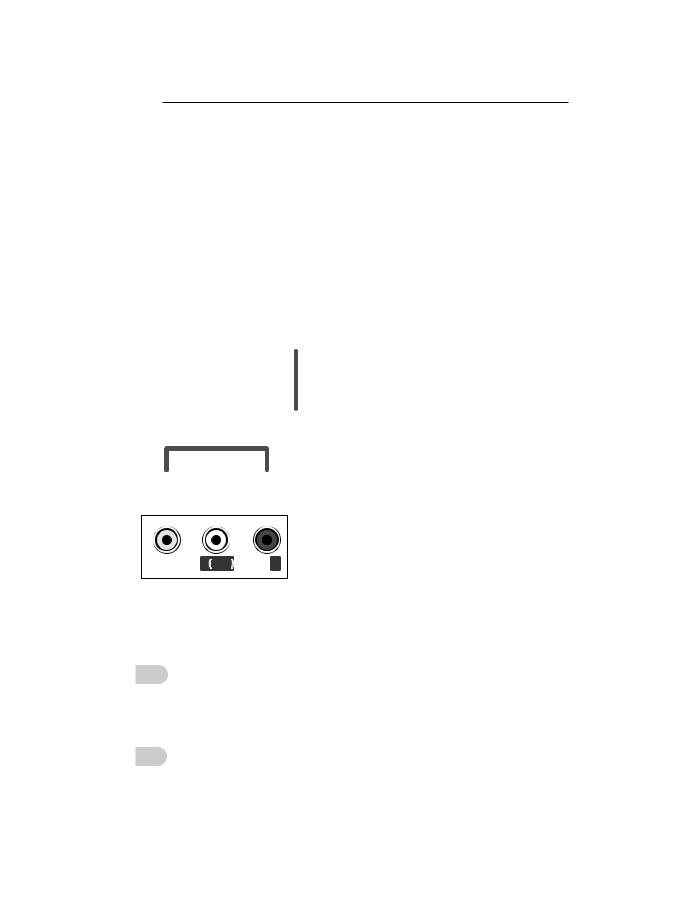
Composite connection
(Only LB86**, LB87**)
IN
AV2 COMPONENT
VIDEO 
 PR P Y
YELLOW  (Use the composite
  gender cable
provided.)
| <![if ! IE]> <![endif]>YELLOW |
<![if ! IE]> <![endif]>WHITE |
<![if ! IE]> <![endif]>RED |
| <![if ! IE]> <![endif]>YELLOW |
<![if ! IE]> <![endif]>WHITE |
<![if ! IE]> <![endif]>RED |
|
|
(*Not |
| <![if ! IE]> <![endif]>YELLOW |
|
Provided) |
| <![if ! IE]> <![endif]>WHITE |
<![if ! IE]> <![endif]>RED |
|
VIDEO |
L (MONO) AUDIO R |
|
DVD / Blu-Ray / HD
Cable Box / VCR
A-18 MAKING CONNECTIONS
(Only LB63**, LB65**, LB67**, LB68**, LB69**,
LB70**, LB72**, LB73**)
MHL connection
| <![if ! IE]> <![endif]>YELLOW |
|
<![if ! IE]> <![endif]>WHITE |
<![if ! IE]> <![endif]>RED |
|
|
(*Not Provided) |
|
| <![if ! IE]> <![endif]>YELLOW |
<![if ! IE]> <![endif]>WHITE |
<![if ! IE]> <![endif]>RED |
|
VIDEO L (MONO) AUDIO
AUDIO R
R
DVD / Blu-Ray / HD Cable Box / VCR
English
Transmits analog video and audio signals from an external device o the TV. Connect the external device and the TV with the composite cable as shown.
Italiano
Il segnale audio e video analogico viene trasmesso da un dispositivo esterno al televisore. Collegare il dispositivo esterno e il televisore mediante il cavo composite come mostrato nell’illustrazione di seguito.
MHL passive cable (*Not Provided)
Mobile phone
English
Mobile High-definition Link (MHL) is an interface for transmitting digital audiovisual signals from mobile phones to television sets.
 NOTE
NOTE
yyConnect the mobile phone to the HDMI IN 3 (MHL) or HDMI/DVI IN 4 (MHL) port to view the phone screen on the TV.
yyThe MHL passive cable is needed to connect the TV and a mobile phone. yyThis only works for the MHL-enabled
phone.
yySome applications can be operated by the remote control.
yyFor some mobile phones supporting MHL, you can control with the Magic Remote. yyRemove the MHL passive cable from the
TV when:
--the MHL function is disabled
--your mobile device is fully charged in standby mode
|
|
|
|
|
|
|
|
|
|
|
MAKING CONNECTIONS A-19 |
||||
|
|
|
|
|
|
|
|
|
|
|
|
|
|
|
|
|
Audio connection |
||||||||||||||
|
Italiano |
|
|||||||||||||
Mobile High-definition Link (MHL) è un’interfaccia |
|
|
|
|
|
|
|
|
|
|
|
|
|
||
per la trasmissione di segnali audiovisivi digitali |
|
|
|
|
|
|
|
|
|
|
|
|
|
||
dai cellulari ai TV. |
|
|
|
|
|
|
|
|
|
|
|
|
|
||
|
|
NOTA |
|
|
|
|
|
|
|
|
|
|
|
|
|
yyCollegare il telefono cellulare alla porta |
|
|
|
|
|
|
|
|
|
|
|
|
|
||
|
HDMI IN 3 (MHL) o HDMI/DVI IN 4 (MHL) |
|
|
|
|
|
|
|
|
|
|
|
|
|
|
|
per visualizzare lo schermo del telefono |
|
|
|
|
|
|
|
|
|
|
|
|
|
|
|
sul TV. |
|
|
|
|
|
|
|
|
|
|
|
|
|
|
|
|
|
|
|
|
|
|
|
|
|
|
|
|
||
yyÈ necessario un cavo passivo MHL per |
|
|
|
|
|
|
|
|
|
|
|
|
|
||
|
collegare il TV a un cellulare. |
|
|
|
|
|
|
|
|
|
|
|
|
|
|
yyQuesta funzione è disponibile soltanto sui |
|
|
|
|
|
|
|
|
|
|
|
|
|
||
|
telefoni che supportano l’interfaccia MHL. |
|
|
|
|
|
|
|
|
|
|
|
|
|
|
yyÈ possibile utilizzare alcune applicazioni |
|
|
|
|
|
|
|
|
|
|
|
|
|
||
|
tramite il telecomando. |
|
|
|
|
|
|
|
|
|
|
|
|
|
|
|
|
|
|
|
|
|
|
|
|
|
|
|
|
||
yyPer alcuni cellulari che supportano la |
|
|
|
|
|
|
|
|
|
|
|
|
|
||
|
|
|
|
|
|
|
|
|
|
|
|
|
|||
|
tecnologia MHL, è possibile utilizzare il |
|
|
|
|
|
|
|
|
|
|
|
|
|
|
|
telecomando magico. |
|
|
|
|
|
|
|
|
|
|
|
|
|
|
yyRimuovere il cavo passivo MHL dal TV |
|
|
|
|
|
|
|
|
|
|
|
|
|
||
|
quando: |
|
|
|
|
|
|
|
|
(*Not Provided) |
|||||
|
--La funzione MHL è disattivata |
|
|
|
|
|
|
|
|
|
|
|
|
|
|
|
--Il dispositivo mobile è completamente |
|
|
|
|
|
|
|
|
|
|
|
|
|
|
|
carico in modalità standby |
|
|
|
|
|
|
|
|
|
|
|
|
|
|
|
|
|
|
|
|
|
|
|
|
|
|
|
|
|
|
|
|
|
|
|
|
|
|
|
|
|
|
|
|
|
|
|
|
|
|
|
|
|
|
|
|
|
|
|
|
|
|
|
|
|
|
|
|
|
|
|
|
|
|
|
|
|
|
|
|
|
|
|
|
|
|
|
|
|
|
|
|
|
|
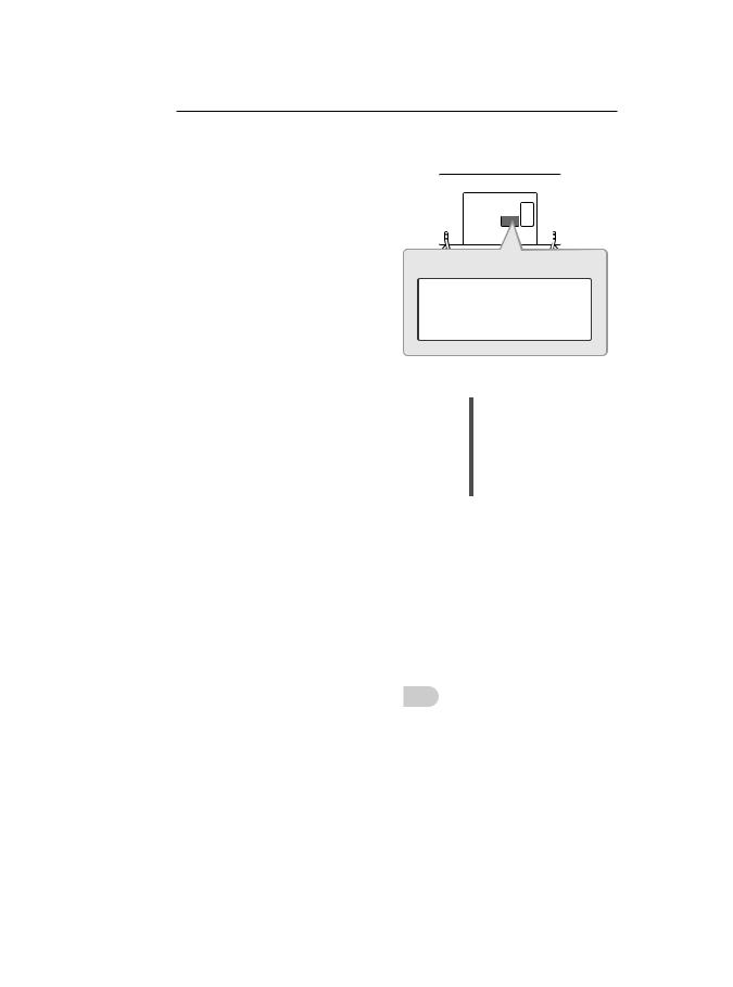
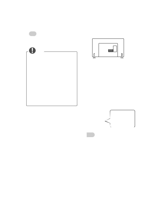
OPTICAL AUDIO IN
Digital Audio System
English
You may use an optional external audio system instead of the built-in speaker.
Digital optical audio connection
Transmits a digital audio signal from the TV to an external device. Connect the external device and the TV with the optical audio cable as shown.
NOTE
yy Do not look into the optical output port. Looking at the laser beam may damage your vision.
yy Audio with ACP (Audio Copy Protection) function may block digital audio output.
A-20 MAKING CONNECTIONS
Italiano USB connection
È possibile utilizzare un sistema audio esterno opzionale al posto dell’altoparlante integrato.
Collegamento audio ottico digitale
Il segnale audio digitale viene trasmesso dal televisore su un dispositivo esterno. Collegare il dispositivo esterno e il televisore con il cavo audio ottico come mostrato nell’illustrazione di seguito.
NOTA
yy Non guardare nella porta dell’uscita ottica. Guardare il raggio laser potrebbe provocare danni alla vista.
yy Contenuti audio con funzione anticopia (ACP, Audio Copy Protection) possono bloccare l’uscita audio digitale.
|
|
|
|
|
|
|
|
|
|
HUB |
|||||
|
|
||||||
HDD |
(*Not Provided) |
||||||
|
|
|
|
|
|
USB |
|
(*Not Provided) |
|
|
|
|
|
||
|
|
(*Not Provided) |
|||||
|
|
|
|
||||
English
Connect a USB storage device such as a USB flash memory, external hard drive, or a USB memory card reader to the TV and access the Smart Share menu to use various multimedia files.
NOTE
yy Some USB Hubs may not work. If a USB device connected using a USB Hub is not detected, connect it to the USB port on the TV directly.
yy Connect the external power source if your USB is needed.
|
|
|
MAKING CONNECTIONS A-21 |
|
|
|
|
|
|
|
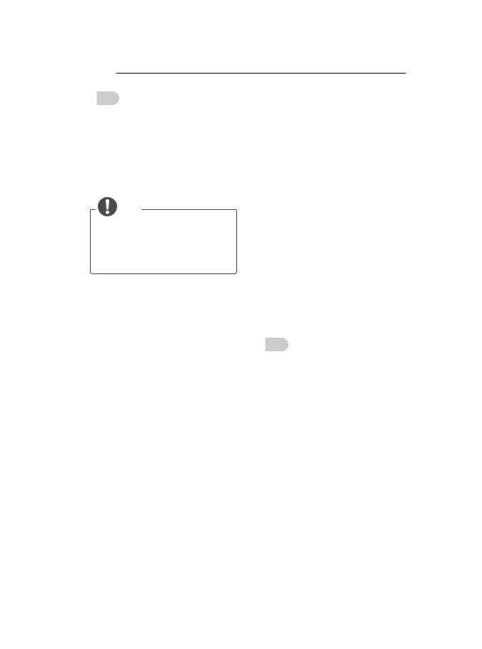
CI module connection |
|||
|
Italiano |
|
||
Collegare una periferica di archiviazione USB, ad esempio una memoria flash USB, un hard disk esterno, o un lettore di schede di memoria USB al televisore e accedere al menu Smart Share per utilizzare diversi file multimediali.
NOTA
yy Alcuni hub USB potrebbero non funzionare. Se una periferica USB collegata tramite un hub USB non viene rilevata, collegarla direttamente alla porta USB della TV.
yy Collegarsi all’alimentazione esterna se il dispositivo USB lo richiede.
(*Not Provided)
English
View the encrypted (pay) services in digital TV mode. This feature is not available in all countries.
NOTE
yy Check if the CI module is inserted into the PCMCIA card slot in the right direction. If the module is not inserted properly, this can cause damage to the TV and the PCMCIA card slot.
yy If the TV does not display any video and audio when CI+ CAM is connected, please contact to the Terrestrial/Cable/ Satellite Service Operator.
A-22 MAKING CONNECTIONS
Italiano Headphone connection
Consente la visione dei servizi codificati (a pagamento) in modalità TV digitale. Questa funzione non è disponibile in tutti i paesi.
NOTA
yy Verificare che il modulo CI sia inserito nello slot della scheda PCMCIA nel verso corretto. Se il modulo non è inserito nel modo corretto, possono verificarsi danni alla TV e allo slot stesso.
yy Se il TV non visualizza o riproduce alcun contenuto video e audio quando è collegata la funzione CAM (modulo di accesso condizionale) con CI+ (Interfaccia comune plus), contattare
l’operatore del servizio terrestre/via cavo/ satellitare.
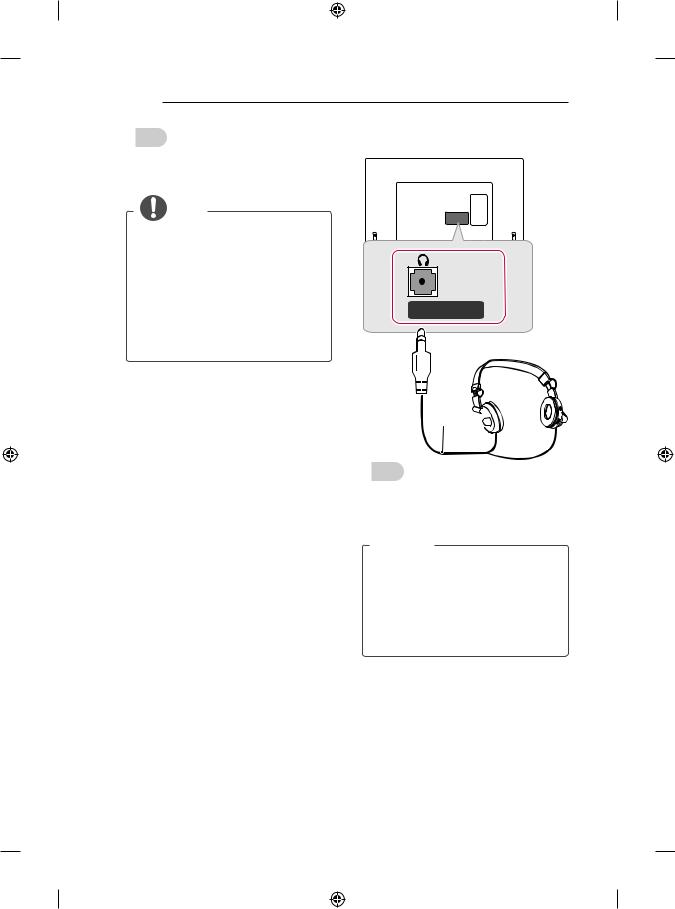
Ext.Speaker / H/P OUT
(*Not Provided) 
English
Transmits the headphone signal from the TV to an external device. Connect the external device and the TV with the headphone as shown.
 NOTE
NOTE
yyAUDIO menu items are disabled when connecting a headphone.
yyOptical Digital Audio Out is not available when connecting a headphone.
yyHeadphone impedance: 16 Ω
yyMax audio output of headphone: 0.624 mW to 1.04 mW
yyHeadphone jack size: 0.35 cm
MAKING CONNECTIONS A-23
Italiano
Consente la trasmissione del segnale delle cuffie dalla TV a un dispositivo esterno. Collegare il dispositivo esterno e la TV con le cuffie come mostrato nell’illustrazione di seguito.
 NOTA
NOTA
yyLe voci del menu AUDIO sono disabilitate se sono collegate le cuffie.
yyL’uscita audio ottica digitale non è disponibile se sono collegate le cuffie.
yyImpedenza cuffie: 16 Ω
yyUscita audio max delle cuffie: da 0,624 mW a 1,04 mW
yyDimensioni jack per cuffia: 0,35 cm
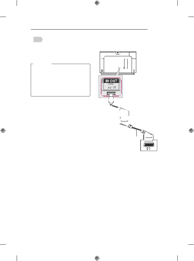
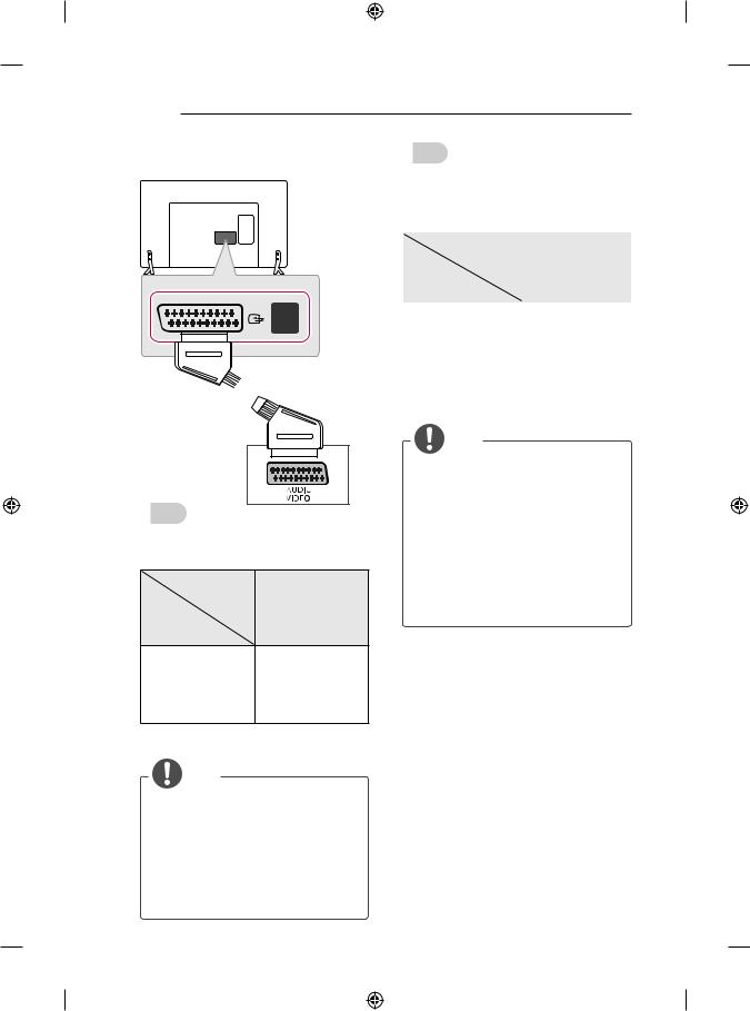
Euro Scart connection
(Only LB86**, LB87**)
(Use the Scart gender cable
provided.)
(*Not Provided)
A-24 MAKING CONNECTIONS
(Only LB63**, LB65**, LB67**, LB68**, LB69**,
LB70**, LB72**, LB73**)
<![if ! IE]><![endif]>IN/OUT
<![if ! IE]><![endif]>AV1

 (*Not Provided)
English
Transmits the video and audio signals from an
external device to the TV set. Connect the external device and the TV set with the euro scart cable as shown.
Output
Type
AV1 Current (TV Out1) input mode
Digital TV |
Digital TV |
|
|
Analogue TV, AV |
|
|
|
Component |
Analogue TV |
HDMI |
|
1TV Out : Outputs Analogue TV or Digital TV signals.
NOTE
yy Any Euro scart cable used must be signal shielded.
yy When watching digital TV in 3D imaging mode, only 2D out signals can be output through the SCART cable. (Only 3D models)
yy If you set the 3D mode to On while a scheduled recording is performed on digital TV, monitor out signals cannot be output through the SCART cable, and the recording cannot be performed. (Only 3D models)
Italiano
Consente la trasmissione dei segnali audio e video da un dispositivo esterno al televisore. Collegare il dispositivo esterno e il televisore con il cavo Euro Scart come mostrato nell’illustrazione di seguito.
Tipo di uscita |
|
Modalità |
AV1 |
(Uscita TV1) |
|
di ingresso |
|
corrente |
|
TV digitale |
TV digitale |
|
|
TV analogica, AV |
|
Component |
TV analogica |
|
|
HDMI |
|
1Uscita TV: uscite segnali TV analogica o TV digitale.
NOTA
yy I cavi Euro Scart devono essere schermati.
yy Quando si guarda il TV digitale in modalità immagini 3D, solo i segnali di uscita 2D possono passare attraverso il cavo SCART. (Solo modelli 3D)
yy Se viene attivata la modalità 3D durante l’esecuzione di una registrazione programmata sul TV digitale, i segnali di uscita monitor non possono venire trasmessi attraverso il cavo SCART e
non è possibile eseguire la registrazione. (Solo modelli 3D)
MAKING CONNECTIONS A-25
English |
Italiano |
Connect various external devices to the TV and switch input modes to select an external
device. For more information of external device’s connection, refer to the manual provided with each device.
Available external devices are: HD receivers, DVD players, VCRs, audio systems, USB storage devices, PC, gaming devices, and other external devices.
NOTE
yy The external device connection may differ from the model.
yy Connect external devices to the TV regardless of the order of the TV port.
yy If you record a TV programme on a DVD recorder or VCR, make sure to connect the TV signal input cable to the TV through a DVD recorder or VCR. For more information of recording, refer to the manual provided with the connected device.
yy Refer to the external equipment’s manual for operating instructions.
yy If you connect a gaming device to the TV, use the cable supplied with the gaming device.
yy In PC mode, there may be noise associated with the resolution, vertical pattern, contrast or brightness. If noise is present, change the PC output to another resolution, change the refresh rate to another rate or adjust the brightness and contrast on the PICTURE menu until the picture is clear.
yy In PC mode, some resolution settings may not work properly depending on the graphics card.
Collegare diversi dispositivi esterni al televisore e modificare la modalità di ingresso per selezionare un dispositivo esterno. Per ulteriori informazioni sul collegamento di un dispositivo esterno, consultare il manuale fornito in dotazione con ciascun dispositivo.
È possibile collegare i seguenti dispositivi esterni: ricevitori HD, lettori DVD, VCR, sistemi audio, periferiche di archiviazione USB, PC, console per videogiochi e altri dispositivi esterni.
NOTA
yy Il collegamento del dispositivo esterno può variare in base al modello.
yy Collegare i dispositivi esterni al televisore a prescindere dall’ordine della porta del televisore.
yy Se si registra un programma TV su un registratore DVD o VCR, accertarsi di collegare il cavo di ingresso del segnale al televisore attraverso un registratore DVD o VCR. Per ulteriori informazioni sulla registrazione, consultare il manuale fornito in dotazione con il dispositivo collegato.
yy Consultare il manuale dell’apparecchiatura esterna per le istruzioni operative.
yy Se si collega una console per videogiochi alla TV, utilizzare il cavo fornito con il dispositivo.
yy In modalità PC, possono essere presenti interferenze relative alla risoluzione, schemi verticali, contrasto o luminosità. In caso di interferenze, modificare la modalità PC impostando un’altra risoluzione o modificando la frequenza di aggiornamento oppure regolare luminosità e contrasto sul menu IMMAGINE finché non si ottiene un’immagine nitida.
yy A seconda della scheda grafica utilizzata, alcune impostazioni di risoluzione potrebbero non essere adatte alla modalità PC.

OWNER’S MANUAL
LED TV*
* LG LED TV applies LCD screen with LED backlights.
Click! User Guide
Please read this manual carefully before operating your set and retain it for future reference.
www.lg.com
<![endif]>ENGLISH
2 TABLE OF CONTENTS
TABLE OF CONTENTS
3 LICENSES
3OPEN SOURCE SOFTWARE NOTICE
3EXTERNAL CONTROL DEVICE SETUP
4SAFETY INSTRUCTIONS
10 - Viewing 3D Imaging (Only 3D models)
12 INSTALLATION PROCEDURE
12 ASSEMBLING AND PREPARING
12 Unpacking
16Separate purchase
17Parts and buttons
19- Using the Joystick button
20Lifting and moving the TV
21Mounting on a table
22Mounting on a wall
23Using Built-in Camera
24- Preparing Built-in Camera
24- Name of Parts of Built-in Camera
24- Checking the Camera’s Shooting Range
25REMOTE CONTROL
27MAGIC REMOTE FUNCTIONS
28Registering Magic Remote
28How to use Magic Remote
29Precautions to Take when Using the Magic Remote
29USING THE USER GUIDE
30MAINTENANCE
30 Cleaning your TV
30 - Screen, frame, cabinet and stand
30 - Power cord
30TROUBLESHOOTING
31SPECIFICATIONS
WARNING
yy If you ignore the warning message, you may be seriously injured or there is a possibility of accident or death.
CAUTION
yy If you ignore the caution message, you may be slightly injured or the product may be damaged.
 NOTE
NOTE
yy The note helps you understand and use the product safely. Please read the note carefully before using the product.
LICENSES / OPEN SOURCE SOFTWARE NOTICE / EXTERNAL CONTROL DEVICE SETUP |
3 |
|
|
LICENSES
Supported licenses may differ by model. For more information about licenses, visit www.lg.com.
OPEN SOURCE SOFTWARE NOTICE
To obtain the source code under GPL, LGPL, MPL and other open source licenses, that is contained in this product, please visit http://opensource.lge.com .
In addition to the source code, all referred license terms, warranty disclaimers and copyright notices are available for download.
LG Electronics will also provide open source code to you on CD-ROM for a charge covering the cost of performing such distribution (such as the cost of media, shipping and handling) upon email request to opensource@lge.com. This offer is valid for three (3) years from the date on which you purchased the product.
EXTERNAL CONTROL DEVICE SETUP
To obtain the external control device setup information, please visit www.lg.com.
<![endif]>ENGLISH

<![endif]>ENGLISH
4 SAFETY INSTRUCTIONS
SAFETY INSTRUCTIONS
Please read these safety precautions carefully before using the product.
 WARNING
yyDo not place the TV and/or remote control in the following environments:
--A location exposed to direct sunlight
--An area with high humidity such as a bathroom
--Near any heat source such as stoves and other devices that produce
heat
--Near kitchen counters or humidifiers where they can easily be exposed to steam or oil
--An area exposed to rain or wind --Near containers of water such as vases
Otherwise, this may result in fire, electric shock, malfunction or product deformation.
yyDo not place the product where it might be exposed to dust. This may cause a fire hazard.
yyMains Plug is the TV connecting/disconnecting device to AC mains electric supply.This plug must remain readily attached and operable when TV is in use.
yyDo not touch the power plug with wet hands. Additionally, if the cord pin is wet or covered with dust, dry the power plug completely or wipe dust off. You may be electrocuted due to excess moisture.
yyMake sure to connect Mains cable to compliant AC mains socket with Grounded earth pin. (Except for devices which are not grounded on earth.) Otherwise possibility you may be electrocuted or injured.
yyInsert power cable plug completely into wall socket otherwise if not secured completely into socket, fire ignition may break out.
yyEnsure the power cord does not come into contact with hot objects such as a heater.
This may cause a fire or an electric shock hazard.
yyDo not place a heavy object, or the product itself, on power cables. Otherwise, this may result in fire or electric shock.
 Loading...