


 Loading...
IN-1
INTRODUCTION - HOW TO USE THIS MANUAL
HOW TO USE THIS MANUAL
IN00U-90
GENERAL INFORMATION
1.INDEX
An INDEX is provided on the first page of each section to guide you to the item to be repaired. To assist you in finding your way through the manual, the Section Title and major heading are given at the top of every page.
2.GENERAL DESCRIPTION
At the beginning of each section, a General Description is given that pertains to all repair operations contained in that section.
Read these precautions before starting any repair task.
3.TROUBLESHOOTING
TROUBLESHOOTING tables are included for each system to help you diagnose the problem and find the cause. The fundamentals of how to proceed with troubleshooting are described on page IN-22 .
Be sure to read this before performing troubleshooting.
4.PREPARATION
Preparation lists the SST (Special Service Tools), recommended tools, equipment, lubricant and SSM (Special Service Materials) which should be prepared before beginning the operation and explains the purpose of each one.
5.REPAIR PROCEDURES
Most repair operations begin with an overview illustration. It identifies the components and shows how the parts fit together.
Example:
|
|
|
|
|
|
|
|
Filler Cap |
|
|
|
|
|
|
|
|||||||
|
|
|
|
|
|
|
|
Float |
|
|
Clevis Pin |
|
|
|||||||||
|
|
|
|
|
|
|
|
Reservoir Tank |
|
Gasket |
|
|
Clip |
|||||||||
|
|
|
|
|
|
|
|
Boot |
|
|
|
|
|
|||||||||
|
|
|
|
|
|
|
|
Grommet |
|
|
|
|
|
|||||||||
|
|
|
|
|
|
|
|
|
|
|
|
|
|
|
||||||||
|
|
|
|
|
|
|
|
|
|
|
|
|
|
|
||||||||
|
|
|
|
|
|
|
|
|
|
|
|
|
|
|
|
|
|
|
|
|
|
|
|
|
|
|
|
|
|
|
|
|
|
|
|
|
|
|
|
|
|
|
|
|
|
|
|
|
|
|
|
|
|
|
|
|
|
|
|
|
|
|
|
|
|
|
|
|
|
Slotted Spring Pin |
|
|
|
|
|
|
|
|
|
|
|
|
|
|
|||||||
|
|
|
12 (120, 9) |
|
|
|
|
|
|
|
|
|
|
|
||||||||
|
|
|
|
|
|
|
|
|||||||||||||||
|
|
|
|
|
|
|
|
|
|
|
|
|
|
|
|
|
|
|
|
|
|
|
|
|
|
|
|
|
|
|
|
|
|
|
|
|
|
|
|
|
|
Clevis |
|
|
|
|
|
|
|
|
|
|
|
|
|
|
|
|
|
|
|
|
|
|||||
|
15 (155, 11) |
|
|
|
|
|
|
|
|
|
|
|
|
|
|
|
|
|
|
|
|
|
|
|
|
|
|
|
|
|
|
|
|
Snap Ring |
|
|
|
|
|||||||
|
|
|
|
|
|
|
|
|
|
|
|
|
|
|
|
|
|
|||||
|
|
|
|
|
|
|
|
|
|
|
|
|
|
|
|
|
|
|||||
|
|
|
|
|
|
|
|
|
|
|
|
|
||||||||||
|
|
|
|
|
|
|
|
|
|
|
|
|
Washer |
|
|
Lock Nut |
|
|
||||
|
|
|
|
|
|
|
|
|
|
|
|
Push Rod |
|
|
|
|
|
|
|
|||
|
|
|
|
|
|
|
|
|
|
Piston |
|
|
|
|
|
|
|
|||||
|
|
|
|
|
|
|
|
|
|
|
|
|
|
|
|
|
|
|
|
|
|
|
|
|
|
|
|
|
|
|
|
|
|
|
|
|
|
|
|
|
|
|
|
|
|
|
|
|
|
|
Cylinder |
|
|
|
|
|
|
|
|
|
|
|
|
|
|
|
||
|
|
|
|
|
|
|
|
|
|
|
|
|
||||||||||
|
N´m (kgf´cm, ft´lbf) |
: Specified torque |
|
|
|
|
|
|
|
|||||||||||||
|
Non-reusable part |
|
|
|
|
|
|
|
|
|
|
|
|
|
|
N17080 |
||||||
|
|
|
|
|
|
|
|
|
|
|
|
|
|
|
|
|
|
|
|
|
|
|
|
|
|
|
|
|
|
|
|
|
|
|
|
|
|
|
|
|
|
|
|
|
|
2005 LEXUS IS300 (RM1140U)
Author : |
Date : |
1 |

IN-2
INTRODUCTION - HOW TO USE THIS MANUAL
The procedures are presented in a step-by-step format:
The illustration shows what to do and where to do it.
The task heading tells what to do.
The detailed text tells how to perform the task and gives other information such as specifications and warnings.
Example:
Illustration: what to do and where
Task heading : what to do
21. CHECK PISTON STROKE OF OVERDRIVE BRAKE
(a)Place SST and a dial indicator onto the overdrive brake piston as shown in the illustration.
SST 09350-30020 (09350-06120)
Set part No. |
Component part No. |
Detailed text : how to do task
(b)Measure the stroke applying and releasing the compressed air (392 785 kPa, 4 8 kgf/cm2 or 57 114 psi) as shown in the illustration.
Piston stroke: 1.40 1.70 mm (0.0551 0.0669 in.)
Specification
This format provides the experienced technician with a FAST TRACK to the information needed. The upper case task heading can be read at a glance when necessary, and the text below it provides detailed information. Important specifications and warnings always stand out in bold type.
6.REFERENCES
References have been kept to a minimum. However, when they are required you are given the page to refer to.
7.SPECIFICATIONS
Specifications are presented in bold type throughout the text where needed. You never have to leave the procedure to look up your specifications. They are also found in Service Specifications section for quick reference.
8. |
CAUTIONS, NOTICES, HINTS: |
|
CAUTIONS are presented presented in bold type, and indicate there is a possibility of injury to you or |
|
other people. |
|
NOTICES are also presented in bold type, and indicate the possibility of damage to the components |
|
being repaired. |
|
HINTS are separated from the text but do not appear in bold. They provide additional information to |
|
help you perform the repair efficiently. |
9. |
SI UNIT |
The UNITS given in this manual are primarily expressed according to the SI UNIT (International System of Unit), and alternately expressed in the metric system and in the English System.
Example:
Torque: 30 N´m (310 kgf´cm, 22 ft´lbf)
2005 LEXUS IS300 (RM1140U)
Author : |
Date : |
2 |
IN-3
INTRODUCTION - IDENTIFICATION INFORMATION
IDENTIFICATION INFORMATION
IN04P-27
VEHICLE IDENTIFICATION AND
ENGINE SERIAL NUMBER
|
|
1. |
VEHICLE IDENTIFICATION NUMBER |
|
|
The vehicle identification number is stamped on the vehicle |
|
|
|
identification number plate and the certification label, as shown |
|
A |
|
in the illustration. |
|
|
|
|
A: Vehicle Identification Number Plate |
|
|
|
B: Certification Label |
|
B |
|
|
|
B12091 |
|
|
|
|
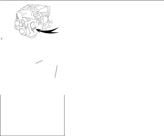
2. |
ENGINE SERIAL NUMBER |
|
|
||
2JZ-GE |
|
||
|
The engine serial number is stamped on the engine block, as |
||
|
|
||
|
|
shown in the illustration. |
|
B12487
2005 LEXUS IS300 (RM1140U)
Author : |
Date : |
3 |
IN-4
INTRODUCTION - REPAIR INSTRUCTIONS
FI1066
Seal Lock Adhesive
Z11554
REPAIR INSTRUCTIONS
IN0DC-15
GENERAL INFORMATION
BASIC REPAIR HINT
(a)Prevent damage and maintain vehicle cleanliness by protective covering on the fender, seat and floor.
(b)During disassembly, line up parts in the order they were removed to facilitate reassembly.
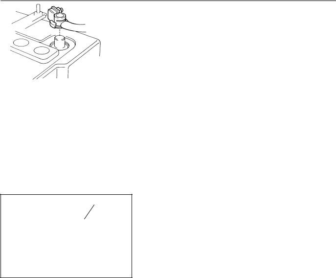
(c)Installation and removal of battery terminal:
(1)Before performing electrical work, disconnect the negative (-) terminal cable from the battery.
(2)If it is necessary to disconnect the battery for inspection or repair, first disconnect the negative (-) terminal cable.
(3)To prevent damage to the battery terminal when disconnecting the terminal cable, loosen the cable nut and raise the cable straight up. Do not twist or pry the cable off.
(4)Clean the battery terminals and cable ends with a clean shop rag. Do not scrape them with a file or other abrasive objects.
(5)Install the cable ends to the battery terminals after loosening the nut, and tighten the nut after installation. Do not use a hammer to tap the cable ends onto the terminals.
(6)Be sure the cover for the positive (+) terminal is properly in place.
(d)Check hose and wiring connectors to make sure that they are connected securely and correctly.
(e)Non-reusable parts:
(1)Always replace cotter pins, gaskets, O-rings, oil seals, etc. with new ones.
(2)Non-reusable parts are indicated in component illustrations by the º º symbols.
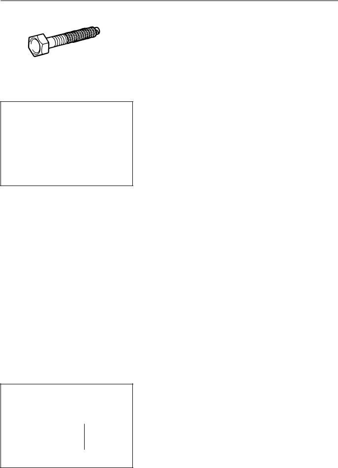
(f)Precoated parts
Precoated parts are bolts, nuts, etc. that are coated with a seal lock adhesive at the factory.
(1)If a precoated part is retightened, loosened or move caused to in any way, it must be recoated with the specified adhesive.
(2)When reusing precoated parts, clean off the old adhesive and dry with compressed air. Then apply new seal lock adhesive to the bolt, nut or threads.
2005 LEXUS IS300 (RM1140U)
Author : |
Date : |
4 |
IN-5
INTRODUCTION - REPAIR INSTRUCTIONS
(3)Precoated parts are indicated in component illustrations by the º º symbols.
(g)When necessary, use a sealer on gaskets to prevent leaks.
(h)Carefully observe all specifications for bolt tightening torques. Always use a torque wrench.
(i)Use of special service tools (SST) and special service materials (SSM) may be required, depending on the nature of the repair. Be sure to use SST and SSM where specified and follow the proper work procedure. A list of SST and SSM can be found in the Preparation section in this manual.
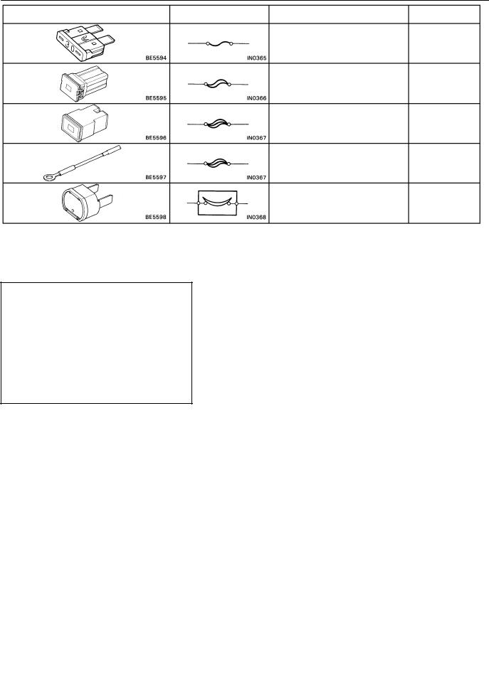
Medium Current Fuse and High Current Fuse |
(j) When replacing fuses, be sure the new fuse has the cor- |
|
rect amperage rating. DO NOT exceed the rating or use |
||
Equal Amperage Rating |
||
|
one with a lower rating. |
BE1367
Illustration |
Symbol |
Part Name |
Abbreviation |
|
|
FUSE |
FUSE |
|
|
MEDIUM CURRENT FUSE |
M-FUSE |
|
|
HIGH CURRENT FUSE |
H-FUSE |
|
|
FUSIBLE LINK |
FL |
|
|
CIRCUIT BREAKER |
CB |
|
|
|
V00076 |
2005 LEXUS IS300 (RM1140U) |
|
|
|
Author : |
Date : |
5 |
IN-6
INTRODUCTION - REPAIR INSTRUCTIONS
WRONG CORRECT
IN0253
WRONG CORRECT
IN0252
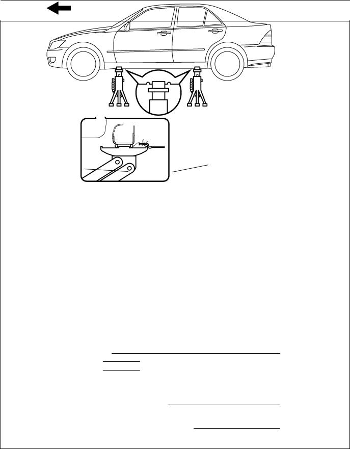
(k)Care must be taken when jacking up and supporting the vehicle. Be sure to lift and support the vehicle at the proper locations (see page IN-8 ).
Release the parking brake on a level surface and shift to in Neutral or N range.
When jacking up the front wheels of the vehicle, at first place chocks behind the rear wheels.
When jacking up the rear wheels of the vehicle, place chocks in front of the front wheels.
When jacking up only the front or rear wheels, set rigid racks and place chocks on front and behind the wheels in contact with the ground.
After the vehicle is jacked up, be sure to support it on rigid racks. It is extremely dangerous to do any work on a vehicle raised on a jack alone, even for a small job that can be finished quickly.
(l)Observe the following precautions to avoid damage to the
following parts:
(1)Do not open the cover or case of the ECU unless absolutely necessary. (Static electricity transmitted through human touch may destroy the IC.)
(2)To disconnect vacuum hoses, pull off the end of the hose, not the middle.
(3)To pull apart electrical connectors, pull on the connector itself, not the wires.
(4)Be careful not to drop electrical components, such as sensors or relays. If they are dropped on a hard floor, they should be replaced and not reused.
(5)When steam cleaning an engine, protect the electronic components, air filter and emission-related components from water.
(6)Never use an impact wrench to remove or install temperature switches or temperature sensors.
(7)When checking continuity at the wire connector, insert the tester probe carefully to prevent terminals from bending.
(8)When using a vacuum gauge, never force the hose onto a connector that is too large. Use a step-down adapter for adjustment. Once the hose has been stretched, it may leak air.
2005 LEXUS IS300 (RM1140U)
Author : |
Date : |
6 |
IN-7
INTRODUCTION - REPAIR INSTRUCTIONS
Example |
|
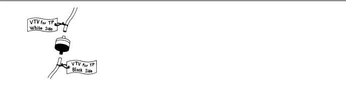
(m) |
Installation and removal of vacuum hose: |
|
|
(1) When disconnecting vacuum hoses, use tags to |
|
|
|
|
|
|
|
|
identify where they should be reconnected to. |
|
|
|
(2) After completing a job, double check that the vacu- |
|
|
|
um hoses are properly connected. A label under the |
|
|
|
hood shows the proper layout. |
|
|
(n) |
Unless otherwise stated, all resistance should be mea- |
|
|
|
sured at an ambient temperature of 20°C (68°F). Mea- |
|
IN0002 |
|
surement should be made after the engine has cooled |
|
|
|
down. If measured at high temperatures immediately af- |
|
|
|
|
|
|
|
ter the vehicle has been running, resistance may be out- |
|
|
|
side specifications. |
2005 LEXUS IS300 (RM1140U)
Author : |
Date : |
7 |
IN-8
INTRODUCTION - REPAIR INSTRUCTIONS
IN04O-16
VEHICLE LIFT AND SUPPORT LOCATIONS
Engine Under Cover No. 2
Front Suspension Member
NOTICE:
Never place the engine under cover No. 2 on the garage jack.
JACK POSITION
Front
Rear
CAUTION :
Front suspension member
Differential carrier
When jacking-up the front and rear, make sure the vehicle is not carrying any extra weight.
PANTOGRAPH JACK POSITION
SUPPORT POSITION
Safety stand and swing arm type lift
I19098
2005 LEXUS IS300 (RM1140U)
Author : |
Date : |
8 |
IN-9
INTRODUCTION - REPAIR INSTRUCTIONS
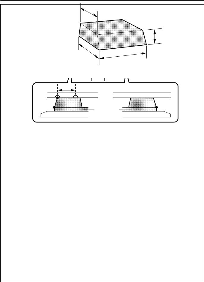
Plate type lift
L
B
Attachment
A C
HINT :
Right and left set position Front and rear set position
Place the vehicle over the center of the lift.
When using attachments, place the one for front side vertically and the one for rear side horizontally to the vehicle.
Align the cushion gum ends of the plate with the attachment lower ends (A, C).
Align the attachment upper end (B) with the rocker flange front side notch.
NOTICE :
Check the interference of the attachment with the front floor cover when placing the attachment on the plate.
Attachment dimensions |
85 mm (3.35 in.) |
70 mm (2.76 in.)
100 mm (3.94 in.)
200 mm (7.87 in.)
I19099
2005 LEXUS IS300 (RM1140U)
Author : |
Date : |
9 |
IN-10
INTRODUCTION - FOR ALL OF VEHICLES
FOR ALL OF VEHICLES
IN0KE-01
PRECAUTION
1.FOR VEHICLES EQUIPPED WITH SRS AIRBAG AND SEAT BELT PRETENSIONER
Negative Cable
BO4111
(a)The LEXUS IS300 is equipped with an Supplemental Restraint System (SRS), such as the driver airbag, front passenger airbag assembly, side airbag assembly, curtain shield airbag assembly and seat belt pretensioners.
Failure to carry out service operations in the correct sequence could cause the supplemental restraint system to unexpectedly deploy during servicing, possibly leading to a serious accident.
Further, if a mistake is made in servicing the supplemental restraint system, it is possible the SRS may fail to operate when required. Before servicing (including removal or installation of parts, inspection or replacement), be sure to read the following items carefully, then follow the correct procedure described in this manual.
(b)GENERAL NOTICE
(1)Malfunction symptoms of the SRS are difficult to confirm, so the diagnostic trouble codes become the most important source of information when troubleshooting. When troubleshooting the supplemental restraint system, always check the diagnostic trouble codes before disconnecting the battery (see page DI-607 ).
(2)Work must be started after 90 seconds from the time the ignition switch is turned to the LOCK position and the negative (-) terminal cable is disconnected from the battery.
(The supplemental restraint system is equipped with a back-up power source so that if work is started within 90 seconds of disconnecting the negative (-) terminal cable from the battery, the SRS may deploy.)
When the negative (-) terminal cable is disconnected from the battery, memory of the clock and audio systems will be cancelled. So before starting work, make a record of the contents memorized by the each memory system. Then when work is finished, reset the clock and audio systems as before. To avoid erasing the memory of each memory system, never use a back-up power supply from another battery.
2005 LEXUS IS300 (RM1140U)
Author : |
Date : |
10 |
IN-1 1
INTRODUCTION - FOR ALL OF VEHICLES
(3)Even in cases of a minor collision where the SRS does not deploy, the steering wheel pad (see page RS17), front passenger airbag assembly (see page RS31), side airbag assembly (see page RS-44 ), curtain shield airbag assembly (see page RS-58 ), front airbag sensor (see page RS-74 ), side and curtain shield airbag sensor assembly (see page RS-79 ) and seat belt pretensioner (see page BO-220 ) should be inspected.
(4)Never use SRS parts from another vehicle. When replacing parts, replace them with new parts.
(5)Before repairs, remove the airbag sensor if shocks are likely to be applied to the sensor during repairs.
(6)Never disassemble and repair the steering wheel pad, front passenger airbag assembly, side airbag assembly, curtain shield airbag assembly, front airbag sensor, side and curtain shied airbag sensor assembly or seat belt pretensioner.
(7)Replace if the airbag sensor, steering wheel pad, front passenger airbag assembly, side airbag assembly, curtain shield airbag assembly, front airbag sensor assembly or seat belt pretensioner if it has been dropped, or if there are cracks, dents or other defects in its case, bracket or connector.
(8)Do not directly expose the steering wheel pad, front passenger airbag assembly, side airbag assembly, curtain shield airbag assembly, front airbag sensor, side and curtain shied airbag sensor assembly or seat belt pretensioner to hot air or flames.
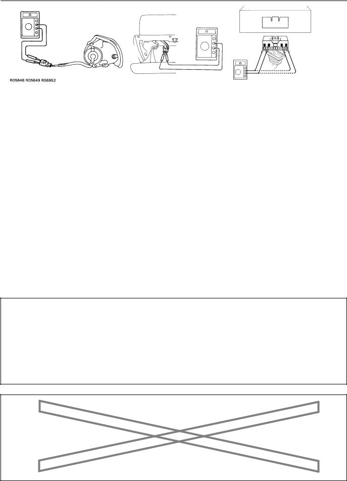
(9)Use a voltmeter/ohmmeter with high impedance (10 kΩ/V minimum) for troubleshooting of the electrical
circuit.
(10)Information labels are attached to the periphery of the SRS components. Follow the instructions on the labels.
(11)After work on the SRS is completed, check the SRS warning light (see page DI-607 ).
(c)SPIRAL CABLE (in Combination Switch)
The steering wheel must be fitted correctly to the steering column with the spiral cable at the neutral position, otherwise cable disconnection and other troubles may result. Refer to SR-25 of this manual concerning correct steering wheel installation.
Marks
F01322
2005 LEXUS IS300 (RM1140U)
Author : |
Date : |
11 |

IN-12
INTRODUCTION - FOR ALL OF VEHICLES
(d)STEERING WHEEL PAD (with Airbag)
(1)When removing the steering wheel pad or handling a new steering wheel pad, it should be placed with the pad top surface facing up see illustration below. Storing the pad with its metallic surface facing upward may lead to a serious accident if the airbag inflates. In addition, do not store a steering wheel pad on top of one another.
(2)Never measure the resistance of the airbag squib. This may cause the airbag to deploy, which is could cause serious injury.
(3)Grease or detergents of any kind should not be applied to the steering wheel pad.
(4)Store the steering wheel pad where the ambient temperature remains below 93°C (200°F), has low humidity and is away from electrical noise.
(5)Before using an electric welder, first disconnect the airbag connector (the connector is yellow and has 4 pins) under the steering column near the combination switch connector.
(6)As a safety measure, always deploy airbags using an SST before disposal (see page RS-17 ). Deploy airbags in a safe place away from electrical noise.
Example:
CORRECT |
WRONG |
|
|
|
B17163 |
Example: |
|
|
|
|
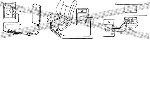
NEVER USE AN OHMMETER ON AN AIRBAG OR PRETENSIONER |
Z13950 |
|
|
|
|
|
2005 LEXUS IS300 |
(RM1140U) |
|
|
|
Author : |
Date : |
12 |
IN-13
INTRODUCTION - FOR ALL OF VEHICLES
(e)FRONT PASSENGER AIRBAG ASSEMBLY
(1)Always store a removed or new front passenger airbag assembly with the airbag deployment direction facing up.
Storing the airbag assembly with the airbag deployment direction facing down could cause a serious accident if the airbag inflate.
(2)Never measure the resistance of the airbag squib. This may cause the airbag to deploy, which is could cause serious injury.
(3)Grease or detergents of any kind should not be applied to the steering wheel pad.
(4)Store the steering wheel pad where the ambient temperature remains below 93°C (200°F), has low humidity and is away from electrical noise.
(5)Before using an electric welder, first disconnect the airbag connector (the connector is yellow and has 4 pins) under the steering column near the combination switch connector.
(6)As a safety measure, always deploy airbags using an SST before disposal (see page RS-31 ). Deploy airbags in a safe place away from electrical noise.
Example:
CORRECT |
WRONG |
H15183 B11669 |
|
|
B17162 |
Example: |
|
|
|
|
NEVER USE AN OHMMETER ON AN AIRBAG OR PRETENSIONER |
Z13951 |
|
|
|
|
|
2005 LEXUS IS300 |
(RM1140U) |
|
|
|
Author : |
Date : |
13 |
IN-14
|
INTRODUCTION - |
FOR ALL OF VEHICLES |
|
|
|
(f) SIDE AIRBAG ASSEMBLY |
|
||
(1) |
Always store a removed or new side airbag assem- |
|||
|
|
bly with the airbag deployment direction facing up. |
||
|
|
Storing the airbag assembly with the airbag deploy- |
||
|
|
ment direction facing down could cause a serious |
||
|
|
accident if the airbag inflates. |
|
|
(2) |
Never measure the resistance of the airbag squib. |
|||
|
|
This may cause the airbag to deploy, which could |
||
|
|
cause serious injury. |
|
|
(3) |
Grease or detergents of any kind should not be ap- |
|||
|
|
plied to the steering wheel pad. |
|
|
(4) |
Store the steering wheel pad where the ambient |
|||
|
|
temperature remains below 93°C (200°F), has low |
||
|
|
humidity and is away from electrical noise. |
|
|
(5) |
Before using an electric welder, first disconnect the |
|||
|
|
airbag connector (the connector is yellow and has |
||
|
|
2 pins) under the steering column near the com- |
||
|
|
bination switch connector. |
|
|
(6) |
As a safety measure, always deploy airbags using |
|||
|
|
an SST before disposal (see page RS-44 ). Deploy |
||
|
|
airbags in safe place away from electrical noise. |
||
|
|
|
|
|
Example: |
|
|
|
|
CORRECT |
WRONG |
|
||
|
|
|
|
B17197 |
|
|
|
|
|
|
|
|
|
|
Example: |
|
|
|
|
|
|
|
||
|
NEVER USE AN OHMMETER ON AN AIRBAG OR PRETENSIONER |
|
B01546 |
|
2005 LEXUS IS300 (RM1140U) |
|
|
|
|
Author : |
Date : |
14 |

IN-15
INTRODUCTION - FOR ALL OF VEHICLES
(g)CURTAIN SHIELD AIRBAG ASSEMBLY
(1)Always store a removed or new side airbag assembly with the airbag deployment direction facing up. Storing the airbag assembly with the airbag deployment direction facing down could cause a serious
accident if the airbag inflates.
NOTICE:
Plastic bag is not re-useable. CAUTION:
Never disassemble the curtain shield airbag assembly.
(2)Never measure the resistance of the airbag squib. This may cause the airbag to deploy, which could cause serious injury.
(3)Grease or detergents of any kind should not be applied to the curtain shield airbag assembly.
(4)Store the steering wheel pad where the ambient temperature remains below 93°C (200°F), has low humidity and is away from electrical noise.
(5)Before using an electric welder, first disconnect the airbag connector (the connector is yellow and has 2 pins) under the steering column near the combination switch connector.
(6)As a safety measure, always deploy airbags using an SST before disposal (see page RS-59 ). Deploy airbags in a safe place away from electrical noise.
Example: |
|
NEVER USE AN OHMMETER ON AN AIRBAG OR PRETENSIONER |
B08605 |
H12059R06952 |
|
2005 LEXUS IS300 (RM1140U)
Author : |
Date : |
15 |
IN-16
INTRODUCTION - FOR ALL OF VEHICLES
(h)SEAT BELT PRETENSIONER
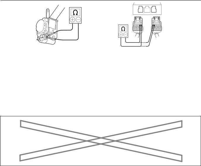
(1)Never measure the resistance of the seat belt pretensioner. This may cause the seat belt pretensioner to activate, which could cause serious injury.
(2)Never disassemble the seat belt pretensioner.
(3)Never install the seat belt pretensioner in another vehicle.
(4)Store the seat belt pretensioner where the ambient temperature remains below 80°C (176°F), has low humidity and is away from electrical noise.
(5)Before using an electric welder, first disconnect the connector (the connector is yellow and has 2 pins).
(6)As a safety measure, always activate the seat belt pretensioner before disposal (see page BO-220 ). Activate the pretensioner in safe place away from electrical noise.
(7)The seat belt pretensioner becomes hot after activation. Allow it to cool before disposing. Never use water to cool seat belt pretensioner.
Example: |
|
NEVER USE OHMMETER ON AN AIRBAG OR PRETENSIONER |
B02121 |
|
2005 LEXUS IS300 (RM1140U)
Author : |
Date : |
16 |

IN-17
INTRODUCTION - FOR ALL OF VEHICLES
(i)AIRBAG SENSOR ASSEMBLY
(1)If an airbag sensor assembly has been involved in a collision where its SRS has deployed, do not reuse it.
(2)The connectors to the airbag sensor assembly should be connected or disconnected with the sensor mounted on the floor. Failure to do so could cause undesired deployment of the SRS.
(3)To avoid serious injury, servicing the SRS must be started 90 seconds after:
The ignition switch is turned to the LOCK position.
The negative (-) terminal cable is discon-
nected from the battery.
Even if only loosening the set bolts of the airbag sensor assembly, you must follow the above guidelines.
(j)WIRE HARNESS AND CONNECTOR
The SRS wire harness is integrated with the instrument panel wire harness assembly. All the connectors in the system are a standard yellow color. If the SRS wire harness becomes disconnected or the connector becomes broken, etc., repair or replace it as shown on page RS-82 .
2005 LEXUS IS300 (RM1140U)
Author : |
Date : |
17 |

IN-18
INTRODUCTION - FOR ALL OF VEHICLES
2. FOR VEHICLES EQUIPPED WITH A CATALYTIC CONVERTER CAUTION:
If large amount of unburned gasoline flows into the converter, it may overheat and create a fire hazard. To prevent this, observe the following precautions and explain them to your customer.
(a)Use only unleaded gasoline.
(b)Avoid prolonged idling.
Avoid running the engine at idle speed for more than 20 minutes.
(c)Avoid spark jump test.
(1)Perform spark jump test only when absolutely necessary. Perform this test as rapidly as possible.
(2)While testing, never race the engine.
(d)Avoid prolonged engine compression measurement.
Engine compression tests must be done as rapidly as possible.
(e)Do not run engine when fuel tank is nearly empty.
This may cause the engine to misfire and create an extra load on the converter.
(f)Avoid coasting with ignition turned off.
(g)Do not dispose of used catalyst along with parts contaminated with gasoline or oil.
3.IF VEHICLE IS EQUIPPED WITH MOBILE COMMUNICATION SYSTEM
For vehicles with mobile communication systems such as two-way radios and cellular telephones, observe the following precautions.
(1)Install the antenna as far as possible away from the ECU and sensors of the vehicle's electronic system.
(2)Install the antenna feeder at least 20 cm (7.87 in.) away from the ECU and sensors of the vehicle's electronic systems. For details about ECU and sensors locations, refer to the section on the applicable component.
(3)Avoid winding the antenna feeder together with other wiring as much as possible, and also avoid running the antenna feeder parallel with other wire harnesses.
(4)Check that the antenna and feeder are correctly adjusted.
(5)Do not install powerful mobile communications system.
4.FOR USING OBD II SCAN TOOL OR HAND-HELD TESTER
CAUTION:
Observe the following items for safety reasons:
Before using the OBD II scan tool or hand-held tester, the OBD II scan tool's instruction book or hand-held tester's operator manual should be read thoroughly.
Be sure to route all cables securely when driving with the OBD II scan tool or hand-held tester connected to the vehicle. (i.e. Keep cables away from feet, pedals, steering wheel and shift lever.)
Two persons are required when test driving with the OBD II scan tool or hand-held tester, one person to drive the vehicle and the other person to operate the OBD II scan tool or hand-held tester.
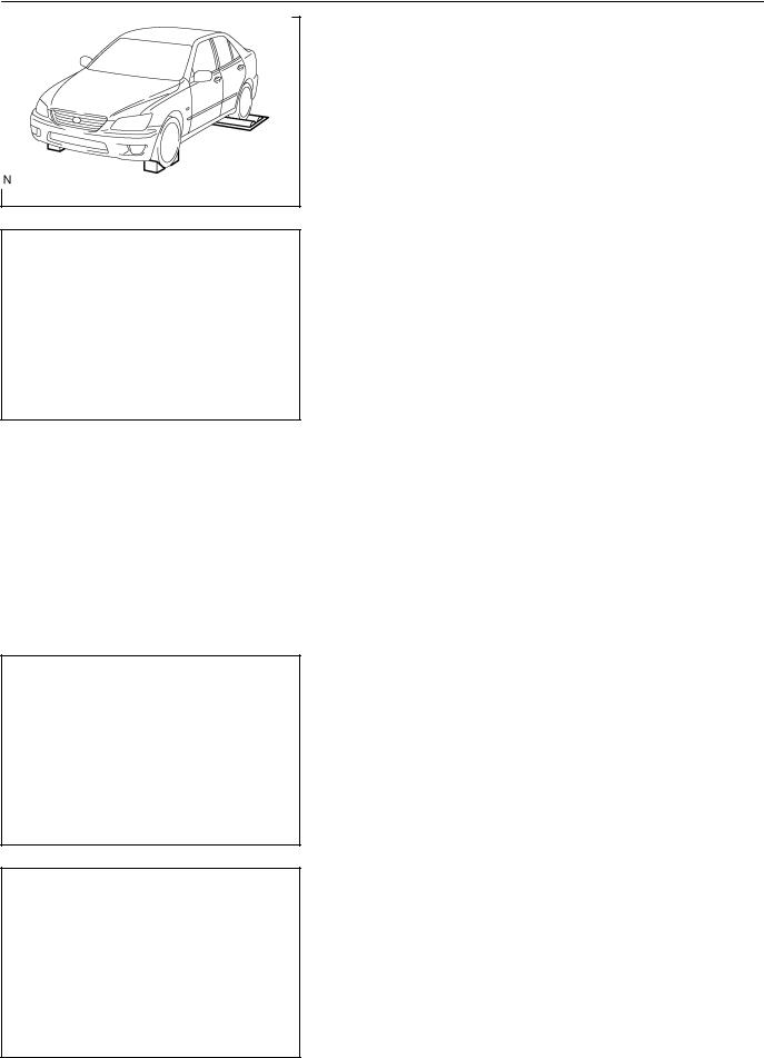
5. FOR VEHICLES EQUIPPED WITH TRACTION CONTROL (TRAC) SYSTEM NOTICE:
When using a 2-wheel drum tester such as a speedometer tester or chassis dynamometer, etc., or jacking up the rear wheels and driving the wheels, always push in the TRAC cut switch and turn the TRAC system OFF.
2005 LEXUS IS300 (RM1140U)
Author : |
Date : |
18 |
IN-19
INTRODUCTION - FOR ALL OF VEHICLES
(a)Press the TRAC cut switch.
(b)Check that the TRAC system is turned OFF by the TRAC cut switch.
HINT:
The SLIP indicator light should be always ON immediately after the engine is restarted.
F12327
(c)Begin measurements.
(d)Press the TRAC cut switch to turn the TRAC to the operative mode and check that the TRAC OFF indicator light goes off.
HINT:
The SLIP indicator light blinks when the TRAC system is operational.
B07101
6.FOR VEHICLES EQUIPPED WITH VEHICLE SKID CONTROL (VSC) SYSTEM
NOTICE:
When using 2-wheel drum tester such as a speedometer tester or chassis dynamometer, etc., or jacking up the front wheels and driving the wheels, always push in the VSC OFF switch to turn the VSC system OFF.
(a)Press the VSC OFF switch.
(b)Check that the VSC OFF indicator light comes ON.
HINT:
The VSC OFF indicator light should be always OFF when the engine is restarted.
B15256
(c)Begin measurements.
(d)Press the VSC OFF switch again to change the VSC system to operational condition and check that the VSC OFF indicator light goes off.
HINT:
The SLIP indicator light blinks and the VSC buzzer sounds when the VSC system is operational.
B07101
2005 LEXUS IS300 (RM1140U)
Author : |
Date : |
19 |
IN-20
INTRODUCTION - FOR ALL OF VEHICLES
7.FOR VEHICLES EQUIPPED WITH LIMITED SLIP DIF-
FERENTIAL
(a)Never apply driving force when RH or LH rear wheel only is touching the ground.
(b)During service/rectification work never spin (race) the RH or LH rear wheel only such as with ON-The-Car type wheel balancer, both rear wheels must be off the ground.
HINT:
In case of the above, due to the construction of the LSD the driving force is transmitted to the opposite wheel and therefore it is possible for the vehicle to start suddenly if only one rear wheel is off the ground. Furthermore it could result in component damage to the LSD due to the loads acting on it.
Always raise both rear wheels off the ground and support the vehicle on suitable safety stand.
B07102
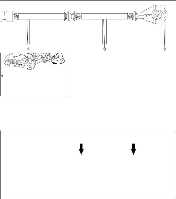
8.INSPECTION AND ADJUSTMENT OF JOINT ANGLE
DURING REMOVAL AND INSTALLATION OF PROPELLER SHAFT
When performing operations which involve the removal and installation of the propeller shaft, always check the joint angle. Make adjustments if necessary (see page PR-1 1).
No. 2 Joint |
No. 3 Joint |
A - B = - 1°21' ± 30' |
B - C = 2°18' ± 30' |
A B C
B07659
2005 LEXUS IS300 (RM1140U)
Author : |
Date : |
20 |
INTRODUCTION - HOW TO TROUBLESHOOT ECU CONTROLLED |
IN-21 |
SYSTEMS |
|
HOW TO TROUBLESHOOT ECU CONTROLLED SYSTEMS
IN04S-45
GENERAL INFORMATION
A large number of ECU controlled systems are used in the LEXUS IS300. In general, ECU controlled systems are considered to be a very intricate, requiring a high level of technical knowledge to troubleshoot. However, following the problem checking procedures of the ECU controlled system's circuits carefully is not complex. If you have an adequate understanding of the system and a basic knowledge of electricity, accurate diagnosis and necessary repair can be performed.
This manual emphasizes the above standpoint to help service technicians perform accurate and effective troubleshooting. Detailed information on major ECU controlled systems in this vehicle are outlined below:
|
System |
Page |
|
|
|
1. |
Engine |
DI-1 |
|
|
|
2. |
Automatic Transmission |
DI-335 |
|
|
|
3. |
ABS with EBD & BA & TRAC System |
DI-435 |
|
|
|
4. |
ABS with EBD & BA & TRAC & VSC System |
DI-505 |
|
|
|
5. |
Supplemental Restraint System |
DI-605 |
|
|
|
6. |
Theft Deterrent System |
DI-776 |
|
|
|
7. |
Cruise Control System |
DI-818 |
|
|
|
8. |
Engine Immobiliser System |
DI-849 |
|
|
|
9. |
Combination Meter System |
DI-870 |
|
|
|
10.Body Control System |
DI-893 |
|
|
|
|
11.Multiplex Communication System |
DI-949 |
|
|
|
|
12.LEXUS Navigation System |
DI-979 |
|
|
|
|
13.Air Conditioning System |
DI-1009 |
|
|
|
|
FOR USING OBDII SCAN TOOL OR HAND-HELD TESTER
Before using the scan tool or tester, the scan tool's instruction book or tester's operator manual should be read thoroughly.
If the scan tool or tester cannot communicate with ECU controlled systems when you have connected the cable of the scan tool or tester to DLC3, turned the ignition switch ON and operated the scan tool, there is a problem on the vehicle side or tool side.
(1)If communication is normal when the tool is connected to another vehicle, inspect the diagnosis data link line (Bus line) or ECU power circuit of the vehicle.
(2)If communication is still not possible when the tool is connected to another vehicle, the problem is probably in the tool itself, so perform the Self Test procedures outlined in the Tester Operator's Manual.
2005 LEXUS IS300 (RM1140U)
Author : |
Date : |
21 |
IN-22 |
INTRODUCTION - HOW TO TROUBLESHOOT ECU CONTROLLED |
|
SYSTEMS |
IN04T-22
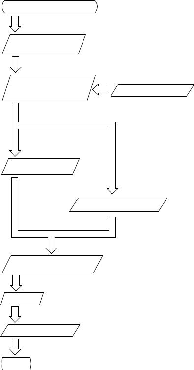
HOW TO PROCEED WITH TROUBLESHOOTING
Carry out troubleshooting in accordance with the procedure below. Only a basic procedure is shown. Details in the Diagnostics section show the most effective methods for each circuit. Confirm troubleshooting procedures first for the relevant circuit before beginning troubleshooting of that circuit.
Vehicle Brought to Workshop
1
1Customer Problem Analysis
2Symptom Confirmation and Diagnostic Trouble Code Check
Ask the customer about the conditions and the environment in which the problem occurred.
3
Symptom Simulation
2, 3
4
6
7
8
Confirm the symptoms and the problem conditions, and check the diagnostic trouble codes.
(When the problem symptoms do not appear during confirmation, use the symptom simulation method described later on.)
Diagnostic Trouble
Code Chart
5
Problem Symptoms Table
Circuit Inspection or Parts Inspection
Repair
Confirmation Test
End
4, 5, 6
Check the results obtained in Step 2. Confirm
the inspection procedure for the system or the part that should be checked using the diagnostic trouble code chart or the problem symptoms table.
7
Check and repair the affected system or part in accordance with the instructions in Step 6.
8
After completing repairs, confirm that the problem has been eliminated.
(To be absolutely sure the problem no longer exists, perform the confirmation test under the same conditions and environment as when it occurred the first time.)
2005 LEXUS IS300 (RM1140U)
Author : |
Date : |
22 |
INTRODUCTION - HOW TO TROUBLESHOOT ECU CONTROLLED |
IN-23 |
SYSTEMS |
|
1.CUSTOMER PROBLEM ANALYSIS
The 5 items in the table below are important points in the problem analysis:
In troubleshooting, the problem symptoms must be confirmed accurately. Preconceptions should be discarded in order to give an accurate judgement. To ascertain what the problem symptoms are, it is extremely important to ask the customer about the problem and the conditions at the time it occurred.
Important Points in the Customer Problem Analysis
What ----- Vehicle model, system name
When ----- Date, time, occurrence frequency
Where ----- Road conditions
Under what conditions? ----- Running conditions, driving conditions, weather conditions
How did it happen? ----- Problem symptoms
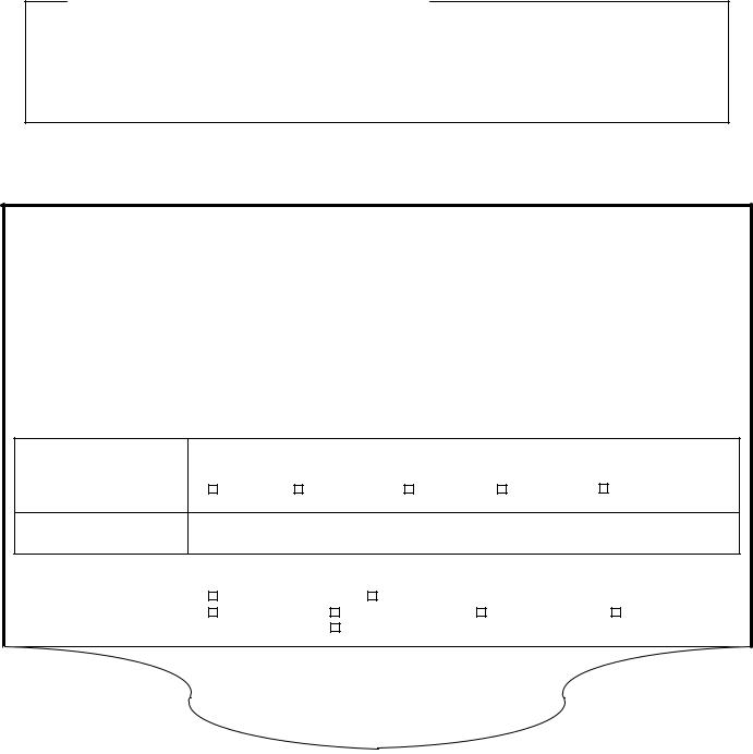
(Sample) Supplemental restraint system check sheet.
CUSTOMER PROBLEM ANALYSIS CHECK
SUPPLEMENTAL RESTRAINT SYSTEM Check Sheet |
|
|
Inspector's |
|
|
|
|
|
||||
|
|
|
|
|
|
|
Name |
|
|
|
|
|
|
|
|
|
|
|
|
|
|
|
|
||
|
|
|
|
|
|
|
|
|
|
|
|
|
|
|
|
|
|
|
|
VIN |
|
|
|
|
|
|
|
|
|
|
|
|
|
|
|
|
|
|
Customer's Name |
|
|
|
|
|
|
Production Date |
|
/ |
/ |
|
|
|
|
|
|
|
|
|
|
|
|
|
|
|
|
|
|
|
|
|
|
Licence No. |
|
|
|
|
|
|
|
|
|
|
|
|
|
|
|
|
|
|
Date Vehicle Brought In |
|
/ |
/ |
|
Odometer Reading |
|
|
km |
||||
|
|
|
|
miles |
||||||||
|
|
|
|
|
|
|
|
|
|
|
|
|
Date Problem First Occurred |
|
|
|
|
|
|
/ |
/ |
|
|||
|
|
|
|
|
|
|
|
|
|
|
||
Weather |
|
Fine |
Cloudy |
|
|
Rainy |
Snowy |
Other |
||||
Temperature |
|
Approx. |
|
|
|
|
|
|
|
|
|
|
|
|
|
|
|
|
|
|
|
|
|
||
|
|
|
Starting |
|
Idling |
|
|
|
|
|
||
Vehicle Operation |
|
Driving |
[ Constant speed |
Acceleration |
Deceleration |
|||||||
|
|
|
|
Other |
|
|
|
|
|
|
] |
|
|
|
|
|
|
|
|
|
|
|
|
|
|
|
|
|
|
|
|
|
|
|
|
|
|
|
2005 LEXUS IS300 (RM1140U)
Author : |
Date : |
23 |

IN-24 |
INTRODUCTION - HOW TO TROUBLESHOOT ECU CONTROLLED |
|
SYSTEMS |
2. SYMPTOM CONFIRMATION AND DIAGNOSTIC TROUBLE CODE CHECK
The diagnostic system in the LEXUS IS300 fulfills various functions.
The first function is the Diagnostic Trouble Code (DTC) Check. In a DTC Check,a previous malfunction's DTC can be checked by a technician during troubleshooting. (A DTC is a code stored in the ECU memory whenever a malfunction in the signal circuits to the ECU occurs.)
Another function is the Input Signal Check, which checks if the signals from various switches are sent to the ECU correctly. By using these check functions, the problem areas can be narrowed down and troubleshooting is more effective. Diagnostic functions are incorporated in the following systems in the LEXUS IS300.
Diagnostic Trouble |
Input Signal Check |
Diagnostic Test |
System |
(Sensor Check) |
Mode (Active Test) |
Code Check |
Engine
(with Check Mode)
Automatic Transmission
(with Check Mode)
ABS with EBD & BA & TRAC System
ABS with EBD & BA & TRAC & VSC System
Supplemental Restraint System
Theft Deterent System
Cruise Control System
Engine Immobiliser System
Combination Meter System
Body Control System
Multiplex Communication System
LEXUS Navigation System
Air Conditioning System
2005 LEXUS IS300 (RM1140U)
Author : |
Date : |
24 |

INTRODUCTION - HOW TO TROUBLESHOOT ECU CONTROLLED |
IN-25 |
SYSTEMS |
|
In diagnostic trouble code check, it is very important to determine whether the problem indicated by the diagnostic trouble code is still occurring or occurred in the past but returned to normal at present. In addition, it must be checked in the problem symptom check whether the malfunction indicated by the diagnostic trouble code is directly related to the problem symptom or not. For this reason, the diagnostic trouble codes should be checked before and after the symptom confirmation to determine the current conditions, as shown in the table below. If this is not done, it may, depending on the case, result in unnecessary troubleshooting for normally operating systems, thus making it more difficult to locate the problem, or in repairs not pertinent to the problem. Therefore, always follow the procedure in correct order and perform the diagnostic trouble code check.
DIAGNOSTIC TROUBLE CODE CHECK PROCEDURE
Diagnostic Trouble |
Confirmation |
Diagnostic Trouble |
Problem Condition |
|
Code Check (Make a |
||||
of Symptoms |
Code Check |
|||
note of and then clear) |
|
|||
|
|
|
||
|
|
|
|
|
Diagnostic Trouble |
Problem symptoms |
Same diagnostic |
Problem is still occurring in the diagnostic |
|
Code Display |
exist |
trouble code is |
circuit |
|
|
|
displayed |
|
|
|
|
|
|
|
|
|
Normal code is |
The problem is still occurring in a place |
|
|
|
displayed |
other than in the diagnostic circuit |
|
|
|
|
(The diagnostic trouble code displayed |
|
|
|
|
first is either for a past problem or it is a |
|
|
|
|
secondary problem) |
|
|
|
|
|
|
|
No problem |
|
The problem occurred in the diagnostic |
|
|
symptoms exist |
|
circuit in the past |
|
|
|
|
|
|
Normal Code Display |
Problem symptoms |
Normal code is |
The problem is still occurring in a place |
|
|
exist |
displayed |
other than in the diagnostic circuit |
|
|
|
|
|
|
|
No problem |
Normal code is |
The problem occurred in a place other |
|
|
symptoms exist |
displayed |
than in the diagnostic circuit in the past |
|
|
|
|
|
2005 LEXUS IS300 (RM1140U)
Author : |
Date : |
25 |
IN-26 |
INTRODUCTION - HOW TO TROUBLESHOOT ECU CONTROLLED |
|
SYSTEMS |
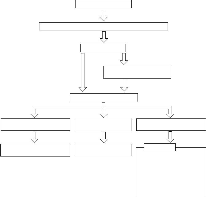
Taking into account the points on the previous page, a flow chart showing how to proceed with troubleshooting using the diagnostic trouble code check is shown below. This flow chart shows how to utilize the diagnostic trouble code check effectively, then by carefully checking the results, indicates how to proceed either to diagnostic trouble code troubleshooting or to troubleshooting of problem symptoms table.
Diagnostic trouble code check
Making a note of and clearing of the diagnostic trouble codes displayed
Symptom confirmation
Problem symptoms |
No problem symptoms |
||
exist |
|||
exist |
|
||
|
|
||
|
Simulation test using the symptom |
||
|
simulation methods |
||
Diagnostic trouble code check
Diagnostic trouble code displayed
Problem symptoms exist
Troubleshooting of problem indicated by diagnostic trouble code
Normal code displayed
Problem symptoms exist
Troubleshooting of each problem symptom
Normal code displayed
No problem symptoms exist
System Normal
If a diagnostic trouble code was displayed in the initial diagnostic trouble code check, it indicates that the trouble may have occurred in a wire harness or connector in that circuit in the past. Therefore, check the wire harness and connectors (see page IN-33 ).
2005 LEXUS IS300 (RM1140U)
Author : |
Date : |
26 |
INTRODUCTION - HOW TO TROUBLESHOOT ECU CONTROLLED |
IN-27 |
SYSTEMS |
|
3.SYMPTOM SIMULATION
The most difficult case in troubleshooting is when no problem symptoms occurring. In such cases, a thorough customer problem analysis must be carried out. Then simulate a simulation of the same or similar conditions and environment in which the problem occurred in the customer's vehicle should be carried out. No matter how much skill or experience a technician has, troubleshooting without confirming the problem symptoms will lead to something important in the repair operation being overlooked and lead to mistakes or delays in repairs.
For example:
With a problem that only occurs when the engine is cold, or occurs as result of vibration caused by road during driving, the problem can never be determined as long as the symptoms are being checked on stationary vehicle or a vehicle with a warmed-up engine.
Vibration, heat or water penetration (moisture) is difficult to reproduce. The symptom simulation tests below are effected substitutes for the conditions and can be applied on a stationary vehicle.
Important Points in the Symptom Simulation Test:
In the symptom simulation test, the problem symptoms as well as problem area or parts must be confirmed. First, narrow down the possible problem circuits according to the symptoms. Then, connect the tester and carry out the symptom simulation test, judging whether the circuit being tested is defective or normal, and also confirming the problem symptoms at the same time. Refer to the problem symptoms table for each system to narrow down the possible causes of the symptom.
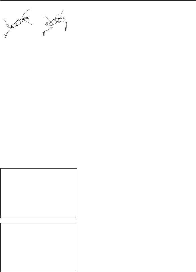
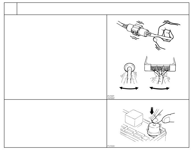
1 VIBRATION METHOD: When vibration seems to be the major cause.
CONNECTORS
Slightly shake the connector vertically and horizontally.
Shake Slightly
WIRE HARNESS
Slightly shake the wire harness vertically and horizontally. The connector joint, fulcrum of the vibration, and body through portion are the major areas that should be checked thoroughly.
PARTS AND SENSOR
Apply slight vibration with a finger to the part of the sensor considered to be the cause of the problem and check whether or not the malfunction occurs.
HINT:
Applying strong vibration to relays may result in open relays.
Swing Slightly
Vibrate Slightly
V07268
2005 LEXUS IS300 (RM1140U)
Author : |
Date : |
27 |
IN-28 |
INTRODUCTION - HOW TO TROUBLESHOOT ECU CONTROLLED |
|
SYSTEMS |
2 HEAT METHOD: When the problem seems to occur when the suspect area is heated.
Heat the component that is the likely cause of the malfunction with a hair dryer or similar device. Check whether or not if the
malfunction occurs.
Malfunction
NOTICE:
(1)Do not heat to more than 60°C (140°F). (Exceeding this temperature may damage components.)
(2)Do not apply heat directly to parts in the ECU.
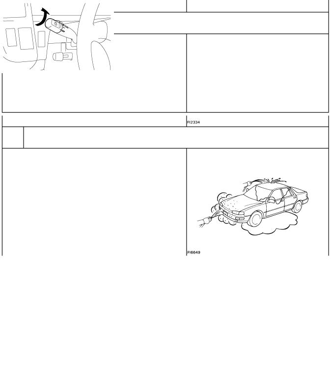
3 WATER SPRINKLING METHOD: When the malfunction seems to occur on a rainy day or in a high-humidity condition.
Sprinkle water onto the vehicle and check whether or not if the malfunction occurs.
NOTICE:
(1)Never sprinkle water directly into the engine compartment. Indirectly change the temperature and humidity by applying water spray onto the front of the radiator.
(2)Never apply water directly onto electronic components.
HINT:
If a vehicle is subject to water leakage, the leaked water may damage the ECU. When testing a vehicle with a water leakage problem, special caution must be taken.
4 OTHER: When a malfunction seems to occur when electrical load is excessive.
Turn on all electrical loads including the heater blower, head |
ON |
lights, rear window defogger, etc. and check to see if the mal- |
|
function occurs. |
|
B02389
B02390
2005 LEXUS IS300 (RM1140U)
Author : |
Date : |
28 |
INTRODUCTION - HOW TO TROUBLESHOOT ECU CONTROLLED |
IN-29 |
SYSTEMS |
|
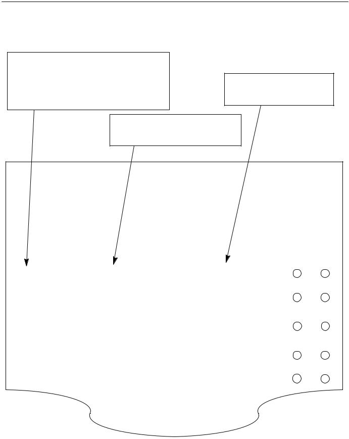
4.DIAGNOSTIC TROUBLE CODE CHART
Use Diagnostic Trouble Codes (DTCs) (from the DTC checks) in the table below to determine the trouble area and proper inspection procedure. The engine diagnostic trouble code chart is shown below as an example.
DTC No.
Indicates the diagnostic trouble code.
Page or Instructions
Indicates the page where the inspection procedure for each circuit is to be found, or gives instructions for checking and repairs.
Trouble Area
Indicates the suspect area of the problem.
Detection Item
Indicates the system of the problem or contents of the problem.
DTC CHART (SAE Controlled)
HINT:
Parameters listed in the chart may not be exactly the same as your reading due to the type of instrument or other factors.
If a malfunction code is displayed during the DTC check mode, check the circuit for that code listed in the table below. For details of each code, refer to the ºSee pageº under the ºDTC No.º in the DTC chart.
DTC No. |
Detection Item |
Trouble Area |
MIL* |
Memory |
||
(See page) |
||||||
|
|
|
|
|||
|
|
|
|
|
|
|
P0100 |
|
Open or short in mass air flow meter circuit |
|
|
||
Mass Air Flow Circuit Malfunction |
Mass air flow meter |
|
|
|||
(DI-24) |
|
|
||||
|
ECM |
|
|
|||
|
|
|
|
|
||
|
|
|
|
|
|
|
P0101 |
Mass Air Flow Circuit |
Mass air flow meter |
|
|
||
(DI-28) |
Range/ Performance Problem |
|
|
|||
|
|
|
||||
|
|
|
|
|
|
|
|
|
|
Open or short in intake air temp. sensor |
|
|
|
P0110 |
Intake Air Temp. Circuit |
circuit |
|
|
||
(DI-29) |
Malfunction |
Intake air temp. sensor |
|
|
||
|
|
|
ECM |
|
|
|
|
|
|
|
|
|
|
P0115 |
Engine Coolant Temp. |
Open or short in engine coolant temp. sensor circuit |
|
|
||
Engine coolant temp. sensor |
|
|
||||
(DI-33) |
Circuit Malfunction |
|
|
|||
ECM |
|
|
||||
|
|
|
|
|
||
P0116 |
Engine Coolant Temp. |
Engine coolant temp. sensor |
|
|
||
(DI-37) |
Circuit Range/ Performance Problem |
Cooling system |
|
|
||
|
|
|
|
|
|
|
|
|
Throttle/ Pedal Position Sensor/Switch |
Open or short in throttle position sensor circuit |
|
|
|
|
|
Throttle position sensor |
|
|
||
|
|
ºAº Circuit Malfunction |
|
|
||
|
|
ECM |
|
|
||
|
|
|
|
|
||
|
|
|
|
|
|
|
|
|
Throttle/ Pedal Position Sensor/ Switch |
|
|
|
|
|
|
ºAº Circuit Range / Performance Prob- |
Throttle position sensor |
|
|
|
|
|
lem |
|
|
|
|
|
|
|
|
|
||
2005 LEXUS IS300 (RM1140U)
Author : |
Date : |
29 |
IN-30 |
INTRODUCTION - HOW TO TROUBLESHOOT ECU CONTROLLED |
|
SYSTEMS |
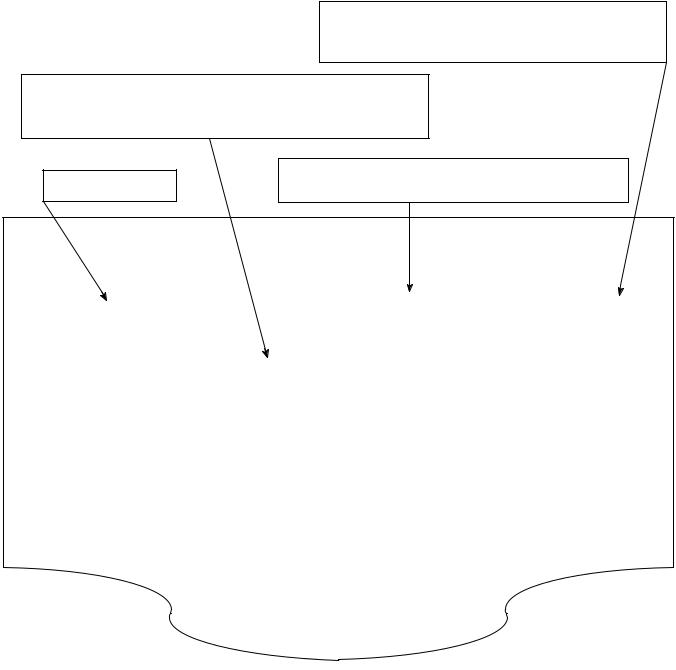
5.PROBLEM SYMPTOMS TABLE
The suspected circuits or parts for each problem symptom are shown in the table below. Use this table to troubleshoot when, during a DTC check, a ºNormalº code is displayed in the diagnostic trouble code check but the problem is still occurring. Numbers in the table show the inspection order in which the circuits or parts should be checked.
HINT:
In some cases, a problem is not detected by the diagnostic system even though a problem symptom is present. It is possible that the problem is occurring outside the detection range of the diagnostic system, or that the problem is occurring in a completely different system.
Page
Indicates the page where the flow chart for each circuit is located.
Circuit Inspection, Inspection Order
Indicates the circuit which needs to be checked for a problem symptom.
Problem Symptom |
Circuit or Part Name |
Indicates the circuit or part which needs to be checked. |
PROBLEM SYMPTOMS TABLE
|
|
|
|
|
|
|
|
|
|
Symptom |
|
Suspect Area |
See page |
||||||
|
|
|
|
|
|
|
|
|
|
Engine does not crank (Does not start) |
1. Starter and starter relay |
ST-2 |
|||||||
ST-17 |
|||||||||
|
|
|
|
|
|
|
|
||
|
|
|
1. ECM power source circuit |
DI-147 |
|||||
No initial combustion (Does not start) |
2. Fuel pump control circuit |
DI-151 |
|||||||
|
|
|
3. Engine control module (ECM) |
IN-29 |
|||||
No complete combustion (Does not start) |
1. Fuel pump control circuit |
DI-151 |
|||||||
|
|
|
|
|
|
|
|
||
|
|
|
1. Starter signal circuit |
DI-144 |
|||||
Engine cranks normally (Difficult to start) |
2. Fuel pump control circuit |
DI-151 |
|||||||
|
|
|
3. Compression |
EM-3 |
|||||
|
|
|
|
|
|
|
|
|
|
Cold engine (Difficult to start) |
1. |
Starter signal circuit |
DI-144 |
||||||
DI-151 |
|||||||||
2. |
Fuel pump control circuit |
||||||||
|
|
|
|||||||
|
|
|
|
||||||
|
|
|
|
|
|
|
|
|
|
Hot engine |
1. |
Starter signal circuit |
DI-144 |
||||||
2. |
Fuel pump control circuit |
DI-151 |
|||||||
|
|
|
|||||||
|
|
|
|
|
|
|
|
|
|
High engine idle speed (Poor idling) |
1. |
A/C signal circuit (Compressor circuit) |
AC-88 |
||||||
2. |
ECM power source circuit |
|
|||||||
|
|
|
|
||||||
|
|
|
|
|
|
|
|
|
|
|
idling) |
1. |
A/C signal circuit |
|
|||||
|
2. |
Fuel pump control circuit |
|
||||||
|
|
||||||||
|
|
|
|
||||||
|
|
|
|
|
|
|
|||
|
|
|
1. Compression |
|
|||||
|
|
|
2. |
Fuel pump control circuit |
|
||||
|
|
|
|
||||||
2005 LEXUS IS300 (RM1140U)
Author : |
Date : |
30 |
Loading...