

Page 1

SECTION 1 –
INSTRUMENTS AND CONTROLS
Gauges, meters and service reminder indicators
Fuel gauge 81. . . . . . . . . . . . . . . . . . . . . . . . . . . . . . . . . . . . . . . . . . . . . . . . . . . . . . . . . . . . . . . . . . . . . . . . .
Engine coolant temperature gauge 82. . . . . . . . . . . . . . . . . . . . . . . . . . . . . . . . . . . . . . . . . . . . . . . . . . . .
Tachometer 84. . . . . . . . . . . . . . . . . . . . . . . . . . . . . . . . . . . . . . . . . . . . . . . . . . . . . . . . . . . . . . . . . . . . . . . .
Odometer and trip meter 86. . . . . . . . . . . . . . . . . . . . . . . . . . . . . . . . . . . . . . . . . . . . . . . . . . . . . . . . . . . . .
Service reminder indicators and warning buzzers 87. . . . . . . . . . . . . . . . . . . . . . . . . . . . . . . . . . . . . . . .
Cruise information display 101. . . . . . . . . . . . . . . . . . . . . . . . . . . . . . . . . . . . . . . . . . . . . . . . . . . . . . . . . . .
Instrument panel light control 104. . . . . . . . . . . . . . . . . . . . . . . . . . . . . . . . . . . . . . . . . . . . . . . . . . . . . . . .
Multi–display light control 105. . . . . . . . . . . . . . . . . . . . . . . . . . . . . . . . . . . . . . . . . . . . . . . . . . . . . . . . . . . .
3
80
Page 2

GAUGES, METERS AND SERVICE REMINDER INDICATORS
FUEL GAUGE
Low fuel level warning light
The gauge indicates the approximate quantity of fuel
remaining in the tank when the ignition switch is on.
It is a good idea to keep the tank over 1/4 full.
If the fuel level approaches “E” or the low fuel level warning light
comes on, fill the fuel tank as soon as possible.
On inclines or curves, due to the movement of fuel in the tank,
the fuel gauge needle may fluctuate or the low fuel level
warning light may come on earlier than usual.
If the fuel tank is completely empty, the malfunction indicator
lamp comes on. Fill the fuel tank immediately.
The indicator lamp goes off after driving several times. If the
indicator lamp does not go off, contact your Lexus dealer as
soon as possible.
It is not a malfunction even if the needle of the fuel gauge
returns to “E” when the ignition switch is turned to the “START”
position.
See the inner back cover for fuel capacity and recommended
fuel selection.
81
Page 3
GAUGES, METERS AND SERVICE REMINDER INDICATORS
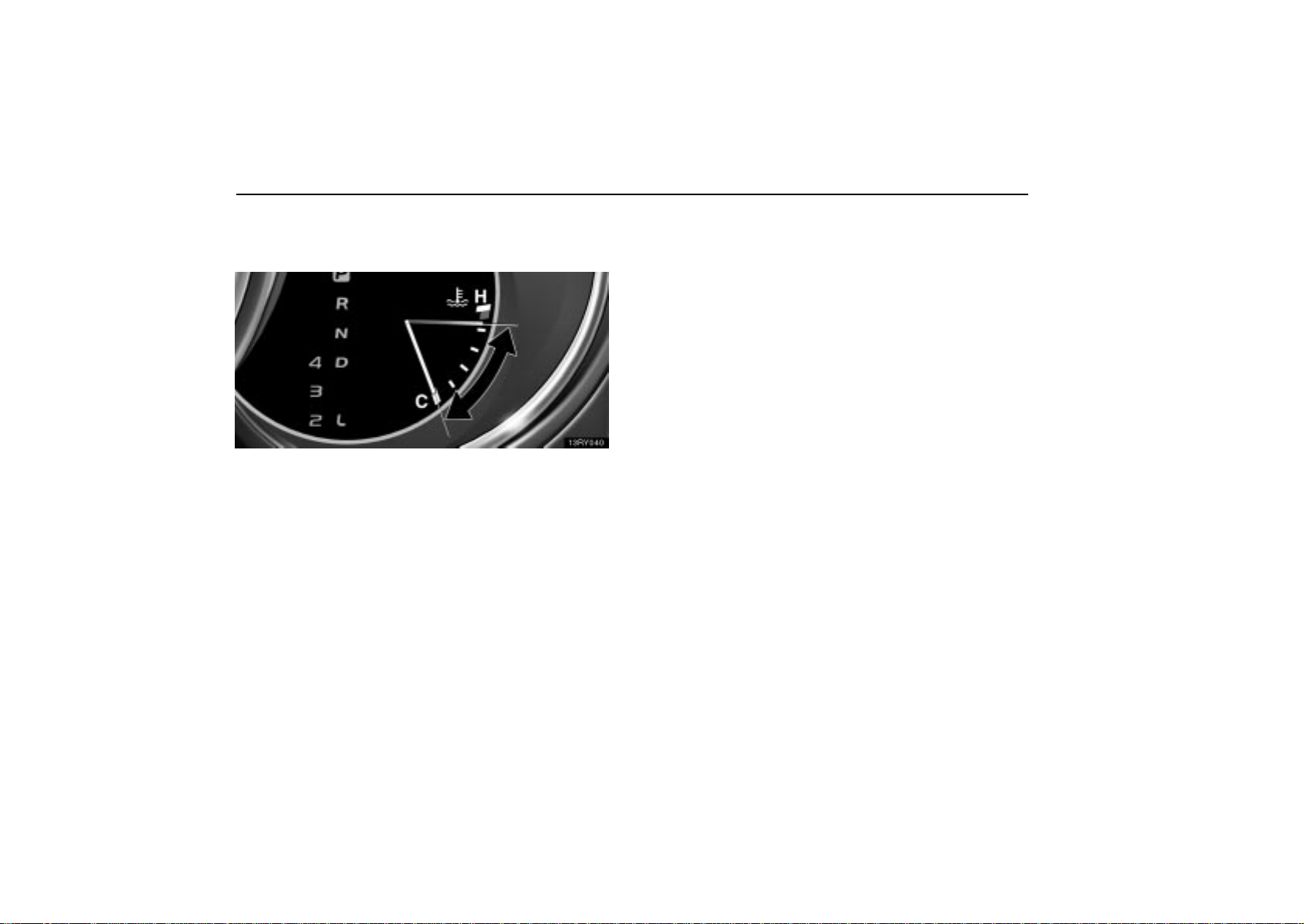
ENGINE COOLANT
TEMPERATURE GAUGE
Normal range
The gauge indicates the engine coolant temperature when
the ignition switch is on. The engine operating
temperature will vary with changes in weather and engine
load.
If the needle points to the red zone or higher, stop your vehicle
and allow the engine to cool.
Y our vehicle may overheat during severe operating conditions,
such as:
Driving up a long hill on a hot day.
Reducing speed or stopping after high speed driving.
Idling for a long period with the air conditioning on in
stop–and–go traffic.
Towing a trailer.
It is not a malfunction even if the needle of the engine coolant
temperature gauge returns to “C” when the ignition switch is
turned to the “START”.
82
Page 4
NOTICE
Do not remove the thermostat in the engine cooling
system as this may cause the engine to overheat. The
thermostat is designed to control the flow of coolant
to keep the temperature of the engine within the
specified operating range.
Do not continue driving with an overheated engine.
See “If your vehicle overheats” on page 556.
GAUGES, METERS AND SERVICE REMINDER INDICATORS
83
Page 5
GAUGES, METERS AND SERVICE REMINDER INDICATORS
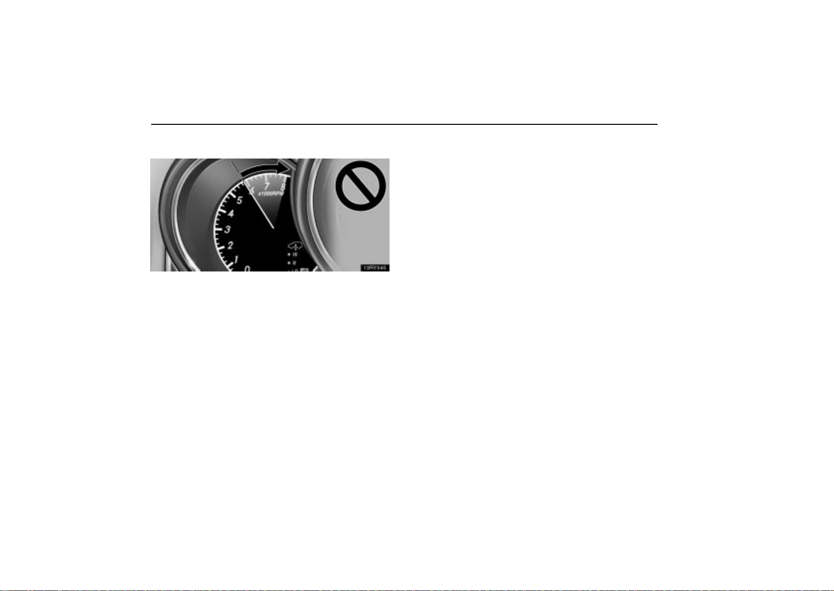
TACHOMETER
The tachometer indicates engine speed in thousands of
rpm (revolutions per minute). Use it while driving to
prevent engine over–revving.
Driving with the engine running too fast causes excessive
engine wear and poor fuel economy. Remember, in most
cases the slower the engine speed, the greater the fuel
economy.
It is not a malfunction even if the needle of the tachometer
returns to the bottom position when the ignition switch is turned
to the “START” position.
84
Page 6
GAUGES, METERS AND SERVICE REMINDER INDICATORS
NOTICE
Do not let the indicator needle get into the red zone. This
may cause severe engine damage.
85
Page 7
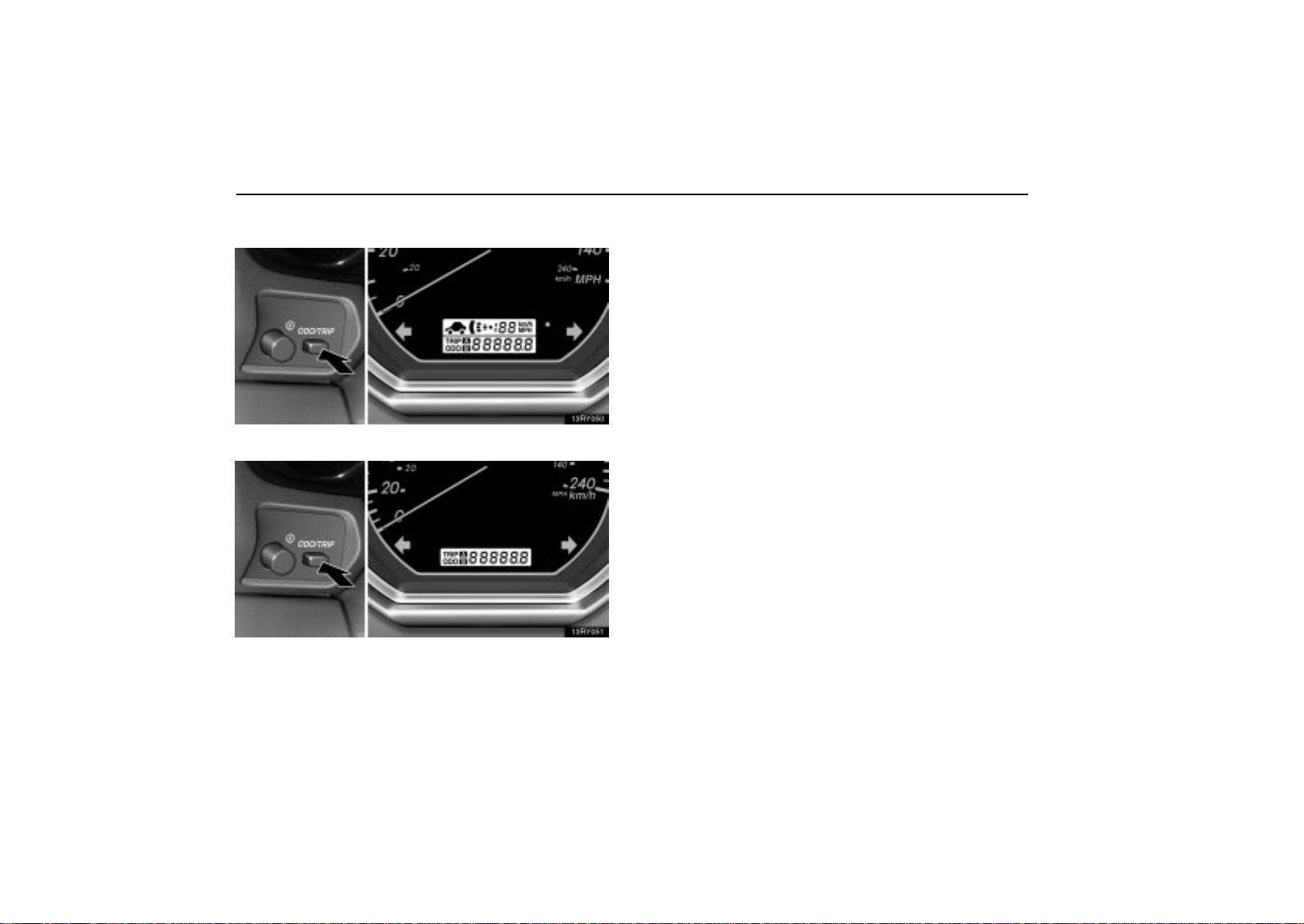
GAUGES, METERS AND SERVICE REMINDER INDICATORS
ODOMETER AND TRIP METER
Vehicles with dynamic laser cruise control
Vehicles without dynamic laser cruise control
This meter displays the odometer and two trip meters. To
change the mode indication, push the “ODO/TRIP” button
briefly . Each time you push the button, the mode changes
in order from the odometer to trip meter A to trip meter B,
then back to the odometer, etc.
The odometer records the total distance the vehicle has
been driven. The twin trip meter records two different
distances independently.
For example, you can use one meter to calculate the fuel
economy and the other to measure the distance on each trip.
To set the A trip meter to zero, display the A meter reading,
push the button and hold it. The same applies for the B trip
meter.
The data of trip meters will be cancelled if the electrical power
source is disconnected.
86
Page 8
GAUGES, METERS AND SERVICE REMINDER INDICATORS
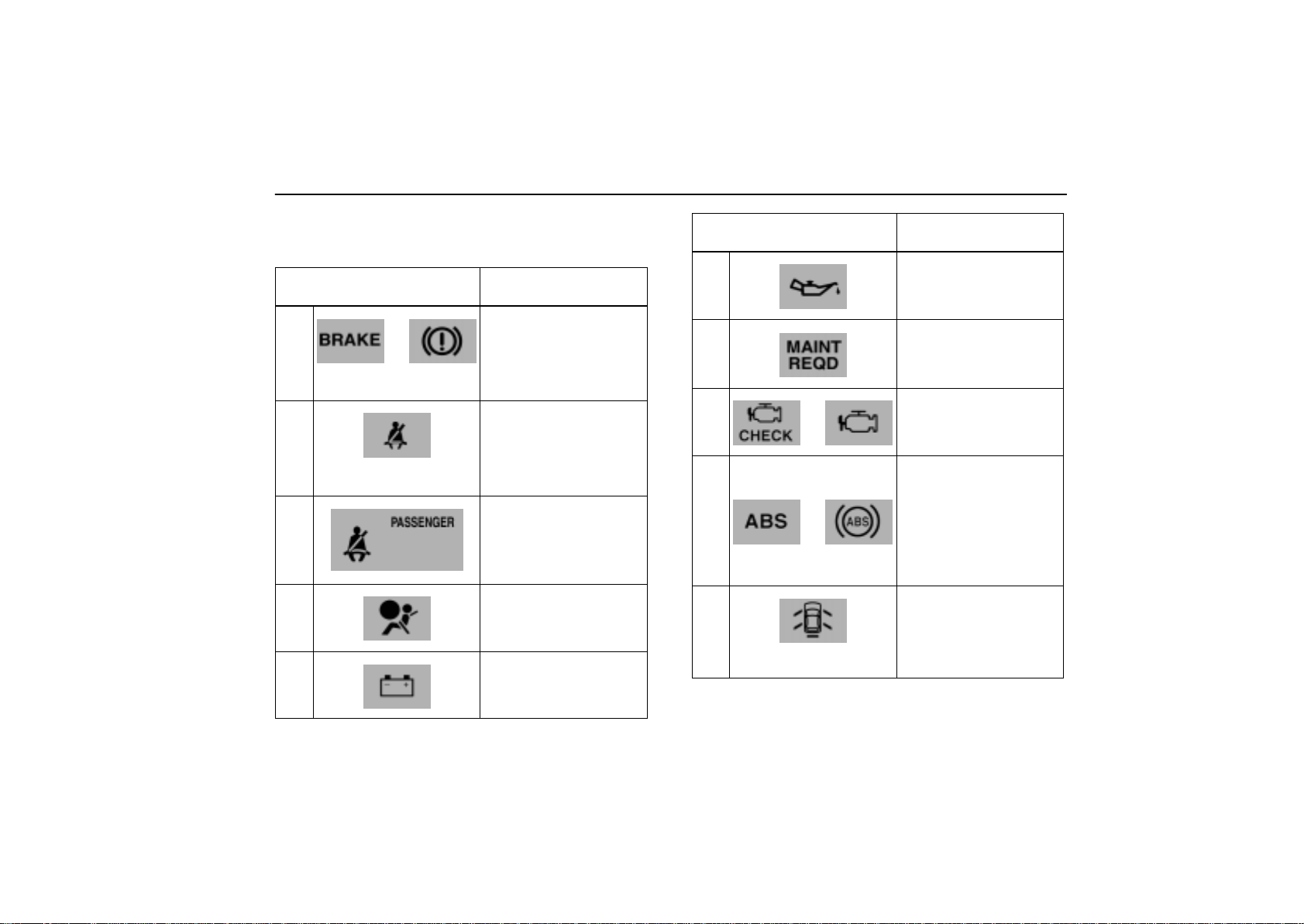
SERVICE REMINDER INDICATORS
AND WARNING BUZZERS
IF THIS INDICATOR OR
BUZZER COMES ON...
(a)
(indicator and buzzer)
or
(b)
(indicator and buzzer)
(c)
(d)
(e)
DO THIS.
If parking brake is off,
stop immediately and
contact Lexus dealer.
Fasten driver’s seat
belt.
Fasten front
passenger’s seat belt.
Take vehicle to Lexus
dealer immediately.
Stop and check.
IF THIS INDICATOR OR
BUZZER COMES ON...
(f)
(g)
(h)
(i)
or
or
13RY028
(j)
(indicator and buzzer)
DO THIS.
Stop and check.
Replace engine oil.
Take vehicle to Lexus
dealer.
Take vehicle to Lexus
dealer.
If brake system
warning light is also
on, stop immediately
and contact Lexus
dealer.
Close all side doors
and back door.
87
Page 9
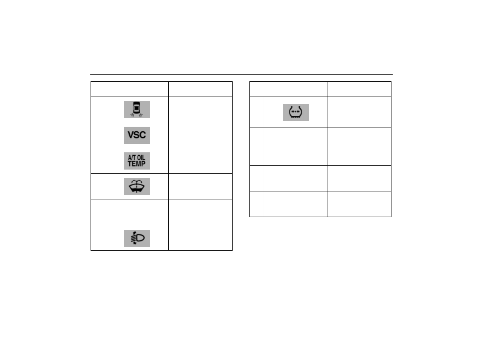
GAUGES, METERS AND SERVICE REMINDER INDICATORS
IF THIS INDICATOR OR
BUZZER COMES ON...
(k)
(l)
(m)
(n)
(o)
Low fuel level
warning light
(p)
DO THIS.
Replace bulb.
Take vehicle to Lexus
dealer.
Stop and check.
Add washer fluid.
Fill up tank.
Take vehicle to Lexus
dealer.
IF THIS INDICATOR OR
BUZZER COMES ON...
(q)
Dynamic laser cruise
(r)
control master warning
light
(s)
Key reminder buzzer
Open moon roof
(t)
reminder buzzer
DO THIS.
Adjust tire inflation
pressure.
If light remains,
contact Lexus dealer.
Check condition
according to warning
code. If system
malfunctions, contact
Lexus dealer.
Remove key.
Close moon roof.
88
Page 10
GAUGES, METERS AND SERVICE REMINDER INDICATORS
(a) Brake System Warning Light and Buzzer
This light comes on in the following cases when the ignition key
is in the “ON” position.
When the parking brake is applied...
This light comes on for a few seconds when the ignition key is
turned to the “ON” position even after the parking brake is
released.
If the vehicle speed rises above 5 km/h (3 mph) with the parking
brake applied, a buzzer sounds.
When the brake fluid level is low...
CAUTION
It is dangerous to continue driving normally when the
brake fluid level is low.
Have your vehicle checked at your Lexus dealer in the
following case:
The light does not come on even if the parking brake is
applied when the ignition key is in the “ON” position.
The light does not come on even if the ignition key is turned
on with the parking brake released.
A warning light turning on briefly during operation does not
indicate a problem.
CAUTION
If either of the following conditions occurs, immediately
stop your vehicle at a safe place and contact your Lexus
dealer.
The light does not turn off even after the parking
brake is released while the engine is running.
In this case, the brakes may not work properly and
your stopping distance will become longer. Depress
the brake pedal firmly and bring the vehicle to an
immediate stop.
The brake system warning light remains on together
with the “ABS” warning light.
In this case, not only the anti–lock brake system will
fail but also the vehicle will become extremely
unstable during braking.
89
Page 11

GAUGES, METERS AND SERVICE REMINDER INDICATORS
(b) Driver’s Seat Belt Reminder Light and Buzzer
The light and buzzer act as a reminder to buckle up the driver’s
seat belt.
Once the ignition key is turned to the “ON” or “START” position,
the reminder light flashes and buzzer sounds if the driver’s seat
belt is not fastened. Unless the driver fastens the belt, the light
continues flashing and the buzzer stops after about 4 to 8
seconds.
(c) Front Passenger’s Seat Belt Reminder Light
The light acts as a reminder to have the front passenger buckle
up the seat belt.
Once the ignition key is turned to the “ON” or “START” position,
the reminder light flashes if a passenger sits in the front
passenger seat and does not fasten the seat belt.
If luggage or other load is placed on the front passenger seat,
depending on its weight, the reminder light may flash.
(d) SRS Warning Light
The indicator comes on when the ignition key is turned to
the “ON” position. It goes off after about 6 seconds. This
means the SRS airbags and front seat belt pretensioners
are operating properly.
This warning light system monitors the airbag sensor
assembly, front airbag sensors, side and curtain shield airbag
sensor assemblies, curtain shield airbag sensor assemblies,
driver’s seat position sensor, driver’s seat belt buckle switch,
front passenger occupant classification system, “AIRBAG ON”
indicator light, “AIRBAG OFF” indicator light, front passenger’s
seat belt buckle switch, front seat belt pretensioner
assemblies, inflators, warning light, interconnecting wiring and
power sources.
If either of the following conditions occurs, this indicates a
malfunction somewhere in the parts monitored by the warning
light system. Contact your Lexus dealer as soon as possible
to service the vehicle.
The light does not come on when the ignition key is turned
to the “ON” position or remains on for more than 6 seconds
or flashes.
The light comes on or starts flashing while driving.
If the light stays on, it indicates that the driver and front
passenger airbags and/or front passenger occupant
classification system, “AIRBAG ON” indicator light and
“AIRBAG OFF” indicator light fail. If the light flashes, the side
and curtain shield airbags and/or seat belt pretensioners have
a problem.
90
Page 12
GAUGES, METERS AND SERVICE REMINDER INDICATORS
(e) Discharge Warning Light
This light warns that the battery is being discharged.
If it comes on while you are driving, stop the vehicle, turn off the
engine, and check for the cause. Look first at the engine drive
belt.
If it is loose or broken, the generator will not charge the
battery properly.
NOTICE
Do not continue driving if the engine drive belt is broken
or loose.
If the belt is O.K., there is a problem somewhere in the
charging system.
The engine ignition will continue to operate, however, until the
battery is discharged. Turn off the air conditioning, blower,
radio, etc., and drive directly to the nearest Lexus dealer or
repair shop.
91
Page 13
GAUGES, METERS AND SERVICE REMINDER INDICATORS
(f) Low Engine Oil Pressure Warning Light
This light warns that the engine oil pressure is too low.
If it flickers or stays on while you are driving, pull off the road
to a safe place and stop the engine immediately. Call a Lexus
dealer or qualified repair shop for assistance.
NOTICE
Do not drive the vehicle with the warning light on —
even for one block. It may ruin the engine.
The light may occasionally flicker when the engine is idling or
it may come on briefly after a hard stop. There is no cause for
concern if it then goes out when the engine is accelerated
slightly.
The light may come on when the oil level is extremely low. It
is not designed to indicate low oil level, and the oil level must
be checked using the oil level dipstick.
92
Page 14

GAUGES, METERS AND SERVICE REMINDER INDICATORS
(g) Engine Oil Replacement Reminder Light (for
vehicles sold in U.S.A.)
This light acts as a reminder when to replace the engine oil.
This light will come on when the ignition key is turned to the
“ON” position and will go off after about a few seconds.
When you drive for about 7200 km (4500 miles) after the
engine oil replacement, this light illuminates for about 3
seconds and then flashes for about 12 seconds with the
ignition key turned to the “ON” position. If you continue driving
without replacing the engine oil, and if the distance driven
exceeds 8000 km (5000 miles), the light will come on after the
ignition key is turned to the “ON” position. The light will remain
on thereafter.
If the light is flashing, we recommend that you replace the
engine oil at a n e a r l y opportunity depending on the driving a nd
road conditions. If the light comes on, replace it as soon as
possible.
The system must be reset after the engine oil replacement.
Reset the system by the following procedure:
1. Turn the ignition key to the “LOCK” position with the
odometer reading shown. (For details, see “Odometer and trip
meter” on page 86.)
2. Turn the ignition key to the “ON” position while holding down
the “ODO/TRIP” button.
Hold down the button for at least 5 seconds. The odometer
indicates “000000” and the light goes off.
If the system fails to reset, the light will continue flashing.
93
Page 15
GAUGES, METERS AND SERVICE REMINDER INDICATORS
(h) Malfunction Indicator Lamp
This lamp comes on when the ignition key is turned to the
“ON” position and goes off after the engine starts. This
means that t h e w a r n i n g light system is operating properly.
If the lamp remains on, or the lamp comes on while driving,
first check the followings.
Empty fuel tank
If the fuel tank is empty, refuel immediately.
Loose fuel tank cap
If the fuel tank cap is loose, securely tighten it.
These cases are temporary malfunctions. The malfunction
indicator lamp will go off after taking several driving trips.
If the lamp does not go off even after several trips, contact your
Lexus dealer as soon as possible.
If the fuel tank is not empty or the fuel tank cap is not
loose...
There is a problem somewhere in the engine, emission
control system, electronic throttle control system, automatic
transmission electrical system or warning light system itself.
Contact your Lexus dealer as soon as possible to service the
vehicle.
If engine speed does not increase when the accelerator pedal
is depressed, there may be a problem somewhere in the
electronic throttle control system.
At this time, vibration may occur. However, if you depress the
accelerator pedal more firmly and slowly, you can drive your
vehicle at low speeds. Have your vehicle checked by your
Lexus dealer as soon as possible.
Even if the abnormality of the electronic throttle control system
is corrected during low speed driving, the system may not be
recovered until the engine is stopped and the ignition key is
turned to the “ACC” or “LOCK” position.
CAUTION
Be especially careful to prevent erroneous pedal
operation.
94
Page 16

GAUGES, METERS AND SERVICE REMINDER INDICATORS
Emissions Inspection and Maintenance (I/M) programs
Your vehicle may not pass a state emission inspection if the
malfunction indicator lamp remains on. Contact your Lexus
dealer to check your vehicle’s emission control system and
OBD (On–Board Diagnostics) system before taking your
vehicle for the inspection.
See “Emissions Inspection and Maintenance (I/M) programs”
on page 594.
(i) “ABS” Warning Light
The light comes on when the ignition key is turned to the “ON”
position. If the anti–lock brake system and the brake assist
system work properly, the light turns off after a few seconds.
Thereafter, if either of the systems malfunctions, the light
comes on again.
When the “ABS” warning light is on (and the brake system
warning light is off), the anti–lock brake system, the brake
assist system, the traction control system and the vehicle
stability control system do not operate, but the brake system
still operates conventionally.
When the “ABS” warning light is on (and the brake system
warning light is off), the anti–lock brake system does not
operate so that the wheels could lock up during a sudden
braking or braking on slippery road surfaces.
95
Page 17
GAUGES, METERS AND SERVICE REMINDER INDICATORS
If either of the following conditions occurs, this indicates
a malfunction somewhere in the components monitored
by the warning light system. Contact your Lexus dealer as
soon as possible to service the vehicle.
The light does not come on when the ignition key is turned
to the “ON” position, or remains on.
The light comes on while you are driving.
A warning light turning on briefly during operation does not
indicate a problem.
CAUTION
If the “ABS” warning light remains on together with the
brake system warning light, immediately stop your
vehicle at a safe place and contact your Lexus dealer.
In this case, not only the anti–lock brake system will fail
but also the vehicle will become extremely unstable
during braking.
(j) Open Door Warning Light and Buzzer
This light remains on until all the side doors and back door are
completely closed.
The light consists of a base light (shape of the vehicle) and 5
separate lights. Each light indicates which door is open.
If the vehicle speed rises above 5 km/h (3 mph) with any door
open, the buzzer will sound and the light keeps flashing until
the door is closed.
(k) Rear Light Failure Warning Light
If this light comes on when the headlight switch is turned on (at
the first or second clickstop), it indicates that one or more of the
tail lights are burned out.
Have defective bulbs replaced as soon as possible.
96
Page 18
GAUGES, METERS AND SERVICE REMINDER INDICATORS
(l) “VSC” Warning Light
This light warns that there is a problem somewhere in the
vehicle stability control system or traction control system.
The light will come on when the ignition key is turned to the
“ON” position and will go off after a few seconds.
If the light comes on while driving, the vehicle stability control
system and traction control system do not work. However, as
conventional braking operates when applied, there is no
problem to continue your driving.
In the following cases, contact your Lexus dealer:
The warning light does not come on after the ignition key is
turned to the “ON” position.
The warning light remains on after the ignition key is turned
to the “ON” position.
The warning light comes on while driving.
Two–wheel drive models only — The “TRAC OFF” indicator
light will come on when the “VSC” warning light comes on even
if the “TRAC OFF” switch is not pushed.
NOTICE
Continued driving with the warning light on may
damage the automatic transmission.
(n) Low Washer Fluid Warning Light
This light comes on when the fluid level in the tank becomes
nearly empty. Fill the tank as soon as possible.
(m) Automatic Transmission Fluid Temperature
Warning Light
(four–wheel drive models only)
This light warns that the automatic transmission fluid
temperature is too high.
If this light comes on while you are driving, slow down and pull
off the road. Stop the vehicle at a safe place and put the
selector lever in “P” and leave the engine idling until the light
goes off. If the light goes off, you can start the vehicle again.
If the light does not go off, call a Lexus dealer or qualified repair
shop for assistance.
(o) Low Fuel Level Warning Light
This light comes on when the fuel level in the tank becomes
nearly empty. Fill the tank as soon as possible.
97
Page 19

GAUGES, METERS AND SERVICE REMINDER INDICATORS
On inclines or curves, due to the movement of fuel in the tank,
the low fuel level warning light may come on earlier than usual.
(p) Automatic Headlight Leveling System Warning
Light (vehicles with discharge headlight only)
This light warns that when there is a problem somewhere in the
automatic headlight leveling system.
The light will come on when the ignition key is turned to the
“ON” position, and will go off after a few seconds.
If it comes on while driving, have your vehicle checked by your
Lexus dealer.
(q) Low Tire Pressure Warning Light
This light warns that tire inflation pressure is critically low. T he
light comes on when the ignition key is turned to the “ON”
position. It goes of f after a few seconds. This indicates that the
low tire pressure warning system is functioning properly.
If the light comes on while driving, adjust tire inflation pressure
to the specified level. (See “Specifications” on page 631.)
Once the ignition switch is turned off, the warning light also go
off. If the light comes on again when the vehicle is started after
adjusting the tire inflation pressure to the specified level, have
the low tire pressure warning system checked at your Lexus
dealer.
If the light blinks once every second, the low tire pressure
warning system may be malfunctioning. Have the system
checked at your Lexus dealer.
If the light blinks twice every second, the low tire pressure
warning system needs to be initialized. For details, see “Tire
pressure warning system” on page 512.
(r) Dynamic Laser Cruise Control Master Warning
Light
This light warns that there is a problem somewhere in the
dynamic laser cruise control system.
The light will come on when the ignition key is turned to the
“ON” position and will go off after a few seconds.
When the light comes on, the alarm sounds and the warning
code will appear on the display. At this time, the dynamic laser
cruise control is cancelled. For details, see “Dynamic laser
cruise control” on page 464.
98
Page 20
GAUGES, METERS AND SERVICE REMINDER INDICATORS
(s) Key Reminder Buzzer
This buzzer acts as a reminder to remove the key when you
open the driver’s door with the ignition key in the “ACC” or
“LOCK” position.
(t) Open Moon Roof Reminder Buzzer
This buzzer acts as a reminder to close the moon roof when
you turn the ignition key to the “ACC” or “LOCK” position and
open the driver’s door.
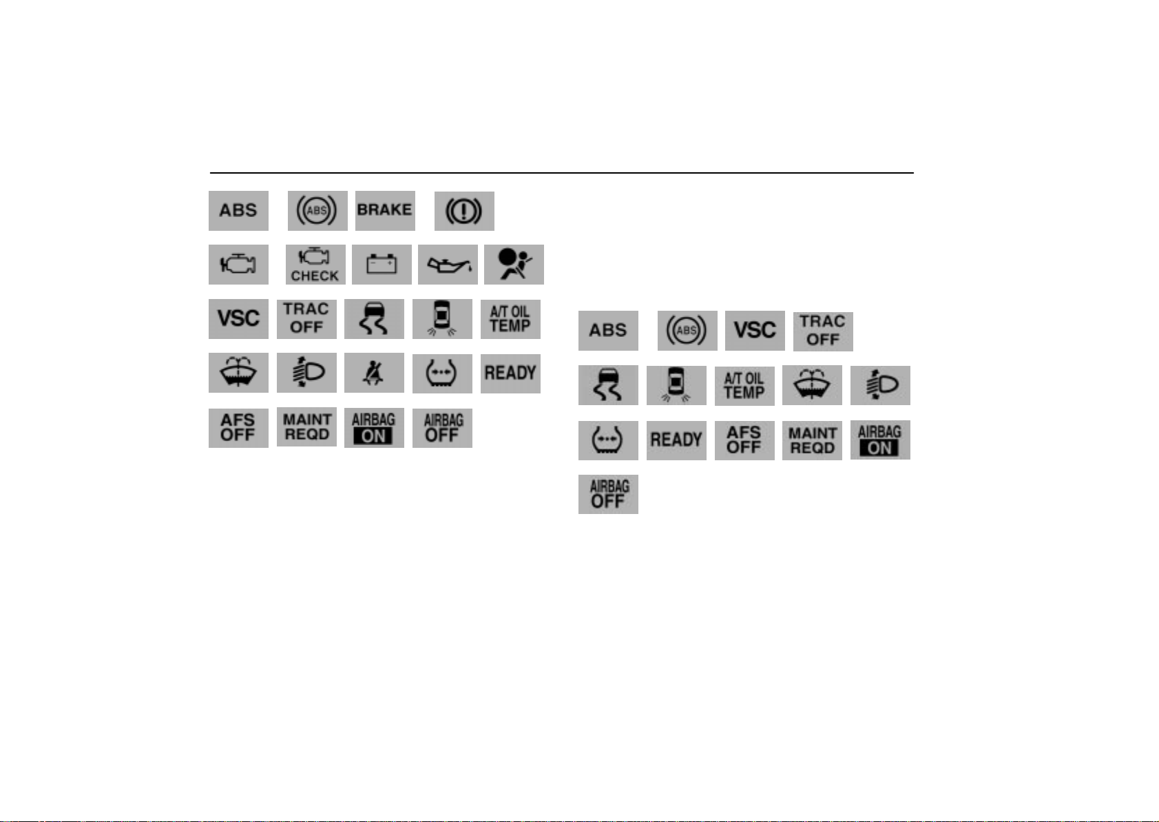
How to check all the service reminder
indicators (except the low fuel level warning
light)
1. Apply the parking brake.
2. Open the door.
The following service reminder indicator should come on. It
goes off when you close the door completely.
13RY028
3. Turn the ignition key to the “ON” position.
The following service reminder indicators should come on.
Height control indicator lights
Height control off indicator light
Easy access mode indicator light
Dynamic laser cruise control master warning light
99
Page 21
GAUGES, METERS AND SERVICE REMINDER INDICATORS
13RY029
or or
or
13RY033
13RY035
13RY032
13RY030
The following service reminder indicators go off after a few
seconds.
Height control indicator lights
Height control off indicator light
Easy access mode indicator light
Dynamic laser cruise control master warning light
or
13RY033
13RY035
13RY030
13RY032
13RY029
100
Page 22
GAUGES, METERS AND SERVICE REMINDER INDICATORS
The following service reminder indicator goes off after 6
seconds.
If any service reminder indicator or warning buzzer does not
function as described above, have it checked by your Lexus
dealer as soon as possible.
CRUISE INFORMATION DISPLAY
101
Page 23
GAUGES, METERS AND SERVICE REMINDER INDICATORS
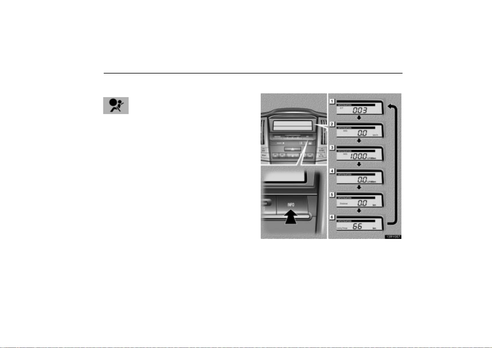
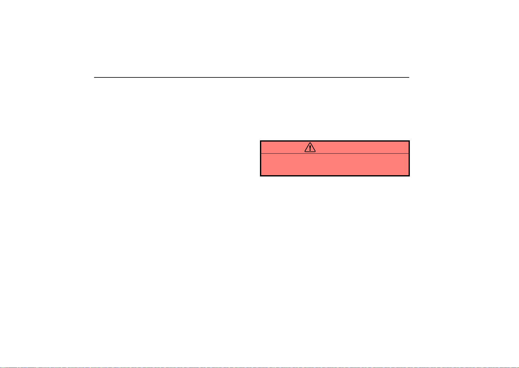
The following information is displayed when you push the
“INFO” button with the ignition switch turned on.
Each time you push the “INFO” button, the display toggles
through this information.
(1) Driving time after engine start
(2) Average vehicle speed after engine start
(3) Average fuel consumption after refueling
(4) Instantaneous fuel consumption
(5) Driving distance after engine start
(6) Driving range
The displayed values in the cruise information display indicate
general driving conditions. Accuracy varies with driving habits
and road conditions.
When the ignition switch is on, the last previously used mode
displayed just before the ignition switch is off will appear.
If the electrical power source has been disconnected from the
cruise information display, the display will automatically be set
to the initial mode.
When the instrument panel lights are turned on, the brightness
of the display will be reduced.
You can adjust the brightness of the display. To adjust the
brightness, see “Multi–display light control” on page 105.
CAUTION
Do not adjust the display while the vehicle is moving.
Be sure to adjust the display only when the vehicle is
stopped.
(1) Driving time after engine start
(“E/T”)
The elapsed time after the engine starts is displayed.
When the engine is started, driving time is counted from 0:00.
Up to 11:59 (11 hours, 59 minutes) can be displayed. When the
driving time exceeds 11:59, the counter returns to 0:00.
The calculation is reset when the ignition switch is turned off.
102
Page 24

GAUGES, METERS AND SERVICE REMINDER INDICATORS
(2) Average vehicle speed after engine start
(“AVG MPH” or “AVG km/h”)
Average vehicle speed after engine start is calculated and
displayed based on total driving distance and total driving
time with the engine running.
The displayed value is updated every 10 seconds.
To reset the calculations, push and hold the “INFO” button for
about 1 second when the display indicates the average vehicle
speed after engine start.
(3) Average fuel consumption after refueling
(“AVG MPG” or “AVG L/100 km”)
Average fuel consumption after refueling is calculated
and displayed based on total driving distance and total
fuel consumption with the engine running.
The displayed value is updated every 10 seconds.
The calculation is reset when the vehicle starts after refueling.
(4) Instantaneous fuel consumption
(“MPG” or “L/100 km”)
The instantaneous fuel consumption is calculated and
displayed based on distance and fuel consumption for 2
seconds with the engine running.
The displayed value is updated every 2 seconds.
Note that an accurate figure may not be shown in the following
cases.
The vehicle is stopped with the engine running. (The display
will indicate the extremely high fuel consumption.)
The vehicle is driving down a long slope applying the engine
brake. (The display will indicate the extremely low fuel
consumption.)
(5) Driving distance after engine start
(“Distance miles” or “Distance km”)
The driving distance after engine start is calculated and
displayed based on vehicle speed after engine running.
The displayed value is updated every time the fuel equivalent
for 0.1 km or 0.1 mile is consumed.
To reset the calculations, push and hold the “INFO” button for
about 1 second when the display indicates the driving distance
after engine start.
103
Page 25
GAUGES, METERS AND SERVICE REMINDER INDICATORS
(6) Driving range
(“Cruising Range miles” or “Cruising Range
km”)
The distance the vehicle can travel with the remaining fuel
is calculated and displayed based on the quantity of
remaining fuel and past fuel consumption.
The driving range display indicates the approximate distance
that you can drive until the fuel gauge reaches “E”. It is different
from the actual distance traveled.
The displayed value is updated every time the fuel equivalent
for 1 mile or 1 km is consumed.
The actual driving range varies with driving habits and road
conditions. If fuel consumption is good, the driving range will
be longer than indicated. If fuel consumption is poor, the
driving range will be shorter than indicated.
If the low fuel level warning light comes on, refuel the vehicle
even if the display indicates that the vehicle can be driven
further.
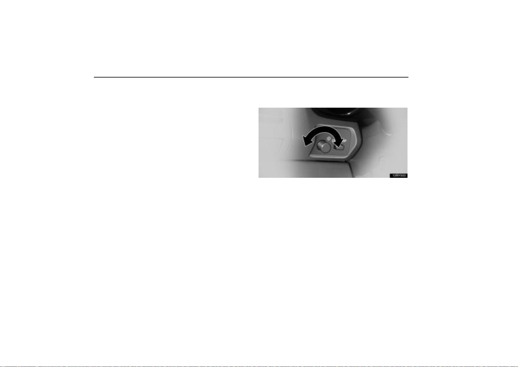
INSTRUMENT PANEL LIGHT
CONTROL
To adjust the brightness of the instrument panel lights,
turn the knob.
With the knob turned fully right, the intensity of the instrument
panel lights will not be reduced when the headlight switch is on.
104
Page 26
GAUGES, METERS AND SERVICE REMINDER INDICATORS
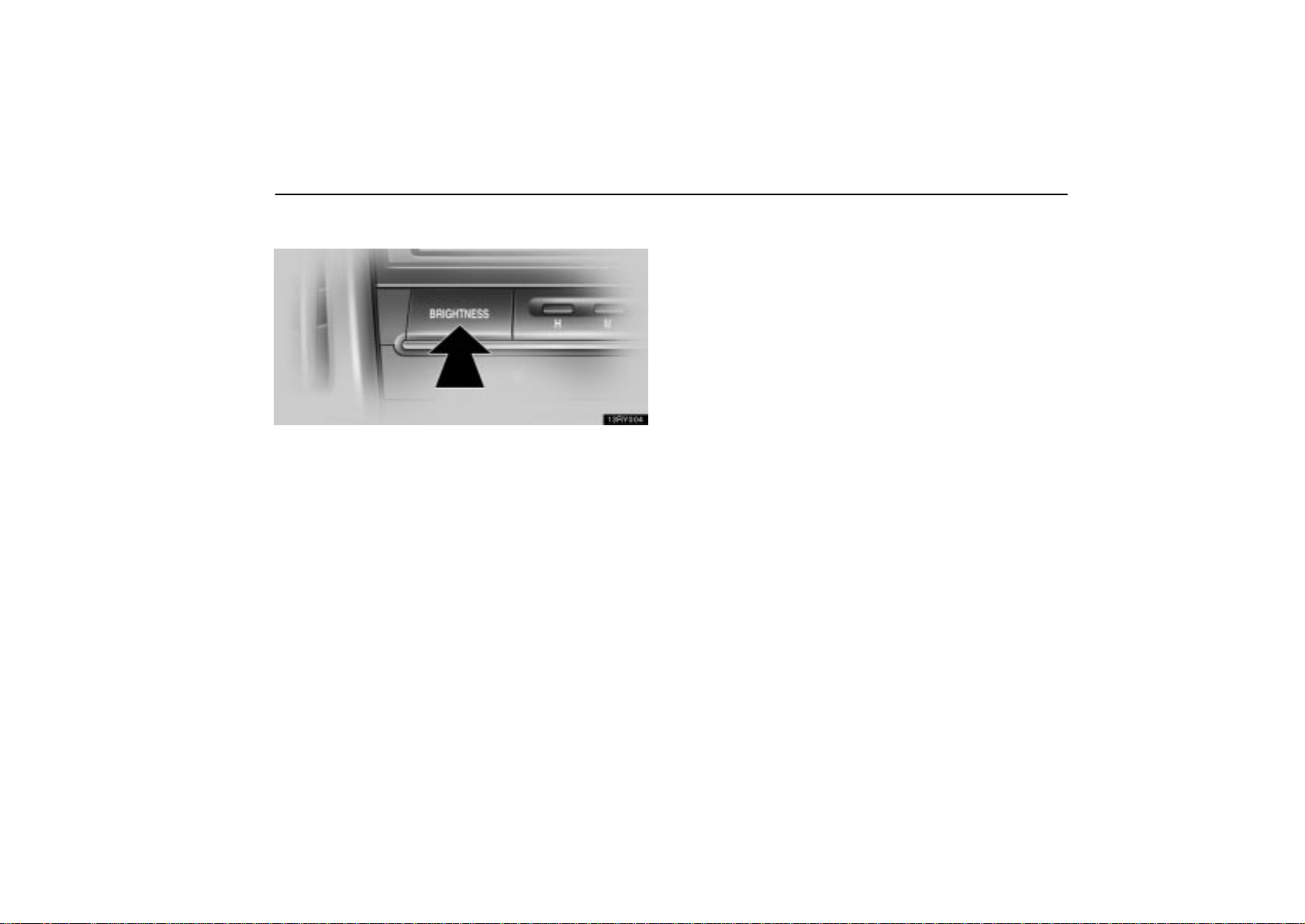
MULTI–DISPLAY LIGHT CONTROL
To adjust the brightness of the multi–display light, push
and release the “BRIGHTNESS” button until the desired
brightness is obtained.
105
Page 27

GAUGES, METERS AND SERVICE REMINDER INDICATORS
106
Page 28

SECTION 1 –
INSTRUMENTS AND CONTROLS
Interior equipment
Sun visors 108. . . . . . . . . . . . . . . . . . . . . . . . . . . . . . . . . . . . . . . . . . . . . . . . . . . . . . . . . . . . . . . . . . . . . . . .
Interior lights 108. . . . . . . . . . . . . . . . . . . . . . . . . . . . . . . . . . . . . . . . . . . . . . . . . . . . . . . . . . . . . . . . . . . . . .
Personal lights 110. . . . . . . . . . . . . . . . . . . . . . . . . . . . . . . . . . . . . . . . . . . . . . . . . . . . . . . . . . . . . . . . . . . . .
Luggage compartment lights 111. . . . . . . . . . . . . . . . . . . . . . . . . . . . . . . . . . . . . . . . . . . . . . . . . . . . . . . . .
Illuminated entry system 111. . . . . . . . . . . . . . . . . . . . . . . . . . . . . . . . . . . . . . . . . . . . . . . . . . . . . . . . . . . .
Clock 113. . . . . . . . . . . . . . . . . . . . . . . . . . . . . . . . . . . . . . . . . . . . . . . . . . . . . . . . . . . . . . . . . . . . . . . . . . . . .
Outside temperature display 114. . . . . . . . . . . . . . . . . . . . . . . . . . . . . . . . . . . . . . . . . . . . . . . . . . . . . . . . .
Power outlets 115. . . . . . . . . . . . . . . . . . . . . . . . . . . . . . . . . . . . . . . . . . . . . . . . . . . . . . . . . . . . . . . . . . . . . .
Rear console box 118. . . . . . . . . . . . . . . . . . . . . . . . . . . . . . . . . . . . . . . . . . . . . . . . . . . . . . . . . . . . . . . . . .
Glove box 120. . . . . . . . . . . . . . . . . . . . . . . . . . . . . . . . . . . . . . . . . . . . . . . . . . . . . . . . . . . . . . . . . . . . . . . . .
Garage door opener 121. . . . . . . . . . . . . . . . . . . . . . . . . . . . . . . . . . . . . . . . . . . . . . . . . . . . . . . . . . . . . . . .
Cupholders 125. . . . . . . . . . . . . . . . . . . . . . . . . . . . . . . . . . . . . . . . . . . . . . . . . . . . . . . . . . . . . . . . . . . . . . . .
Overhead console box 128. . . . . . . . . . . . . . . . . . . . . . . . . . . . . . . . . . . . . . . . . . . . . . . . . . . . . . . . . . . . . .
Auxiliary boxes 130. . . . . . . . . . . . . . . . . . . . . . . . . . . . . . . . . . . . . . . . . . . . . . . . . . . . . . . . . . . . . . . . . . . .
Auxiliary box and grocery bag hooks 131. . . . . . . . . . . . . . . . . . . . . . . . . . . . . . . . . . . . . . . . . . . . . . . . . .
Luggage cover 133. . . . . . . . . . . . . . . . . . . . . . . . . . . . . . . . . . . . . . . . . . . . . . . . . . . . . . . . . . . . . . . . . . . . .
Floor mat 136. . . . . . . . . . . . . . . . . . . . . . . . . . . . . . . . . . . . . . . . . . . . . . . . . . . . . . . . . . . . . . . . . . . . . . . . .
Tie-down hookss 137. . . . . . . . . . . . . . . . . . . . . . . . . . . . . . . . . . . . . . . . . . . . . . . . . . . . . . . . . . . . . . . . . .
4
107
Page 29
INTERIOR EQUIPMENT
SUN VISORS
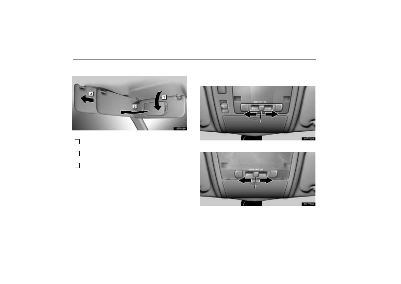
To block out glare, move the sun visor as shown.
1
To block out glare from the front , swing the sun visor
down.
2
To block out glare from the side, remove the sun visor
from the hook and swing it to the side.
3
To block out glare coming obliquely from behind you,
slide the visor backwards.
At this position, the vanity light does not come on.
INTERIOR LIGHTS
Front
Vehicles with moon roof
108
Vehicles without moon roof
Page 30
INTERIOR EQUIPMENT
To turn on the interior light, slide the switch.
The interior light switch has the following positions:
“ON” — Keeps the light on all the time.
“OFF” — Turns the light off.
“DOOR” — Turns the light on when any of the side doors or
back door is opened. The light goes of f when all the side doors
and back door are closed. For details, see “Illuminated entry
system” on page 111.
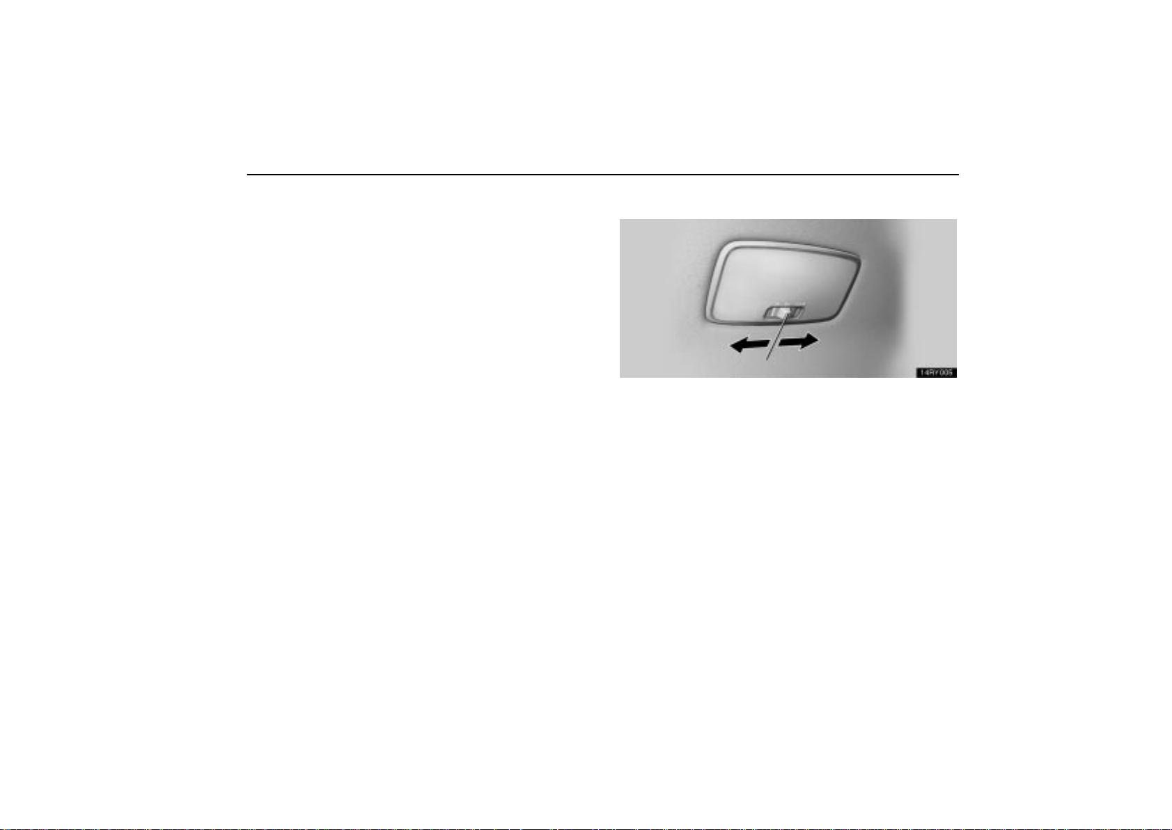
Rear
To turn on the interior light, slide the switch.
The interior light switch has the following positions:
“ON” — Keeps the light on all the time.
“OFF” — Turns the light off.
“DOOR” — Turns the light on when any of the side doors or
back door is opened. The light goes of f when all the side doors
and back door are closed. For details, see “Illuminated entry
system” on page 111.
109
Page 31
INTERIOR EQUIPMENT
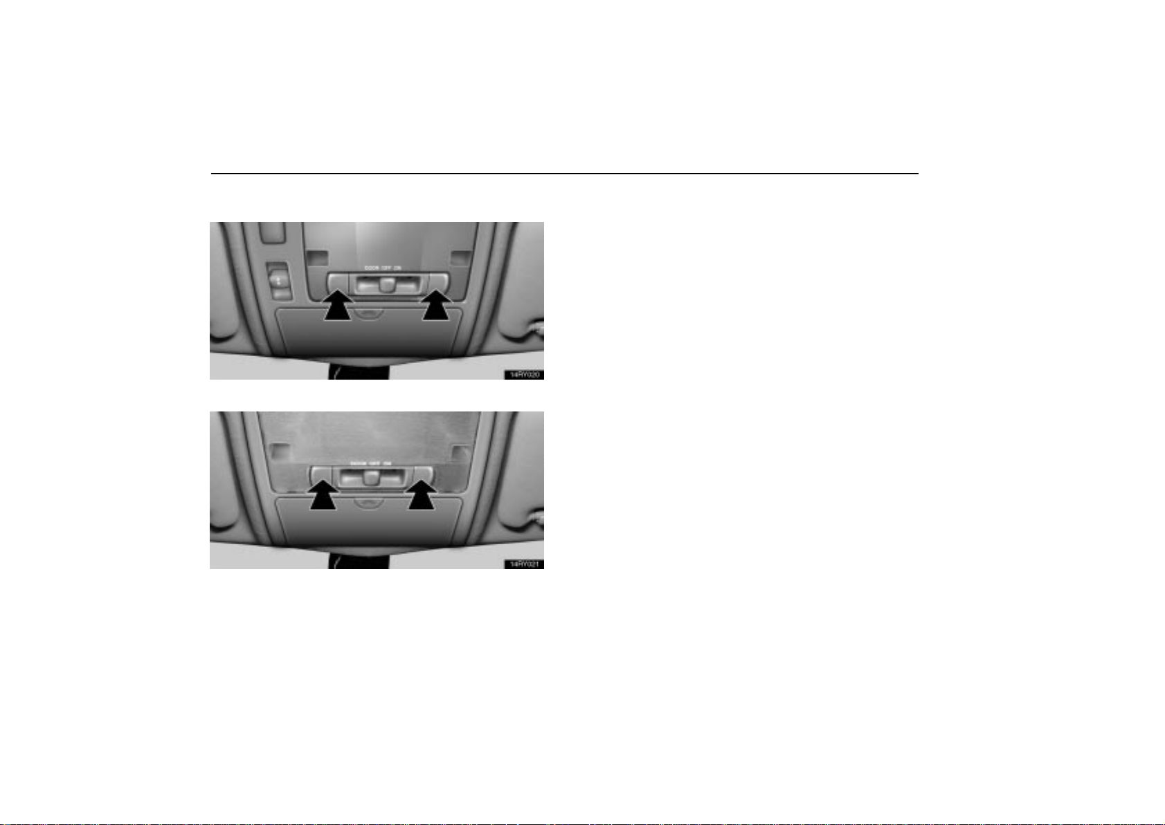
PERSONAL LIGHTS
Vehicles with moon roof
Vehicles without moon roof
To turn on the personal light, push the switch. To turn it
off, push the switch again.
110
Page 32
INTERIOR EQUIPMENT
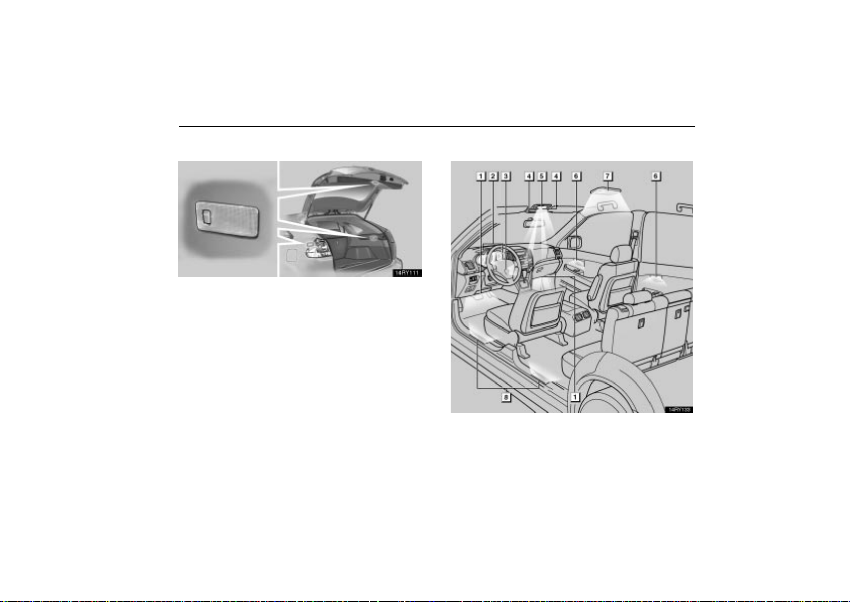
LUGGAGE COMPARTMENT LIGHTS
To turn on the luggage compartment light, open the back
door and push the switch. The light goes off when the
back door is closed.
ILLUMINATED ENTRY SYSTEM
111
Page 33

INTERIOR EQUIPMENT
1
Foot lights (on some models)
2
Meter ring light
3
Ignition switch light
4
Center console spot lights
5
Front interior light (with the “DOOR” position)
6
Inside door handle lights (on some models)
7
Rear interior light (with the “DOOR” position)
8
Scuff plate lights (on some models)
All of the lights except the center console spot lights and
meter ring light will come on when any of the side doors
are opened.* After all the doors are closed, the lights
remain on for about 15 seconds before fading out.**
NOTE:
* The operating condition can be changed.
** The duration of lighting can be changed.
Ask your Lexus dealer for details.
However, in the following cases, the lights go out immediately:
All of the lights except the center console spot lights and
meter ring light — All the side doors and back door are
locked.
Ignition switch light, front interior light, rear interior light and
scuff plate lights — All the side doors are closed and the
ignition key is in the “ACC” or “ON” position.
When any of the side doors is unlocked, all of the lights except
the center console spot light and meter ring light will come on
and remain on for about 15 seconds before fading out.
To prevent the battery from being discharged, all of the lights
will automatically turn off when the ignition key is removed and
the door is left opened for about 20 minutes.
Ignition switch light, front interior light, rear interior light
and scuff plate lights
The ignition switch light, front interior light, rear interior light and
scuff plate lights also come on and remain on for about 15
seconds before fading out when the ignition switch is turned to
the “LOCK” position.
112
Page 34
INTERIOR EQUIPMENT
Foot lights and inside door handle lights
The foot lights and inside door handle lights also come on when
the ignition switch is in the “ON” position with the selector lever
in the “P” position. When the selector lever is moved out of the
“P” position, the intensity of the foot lights and inside door
handle lights will be reduced.*
NOTE:
* The intensity of the foot lights and inside door handle lights
can be changed.
Ask your Lexus dealer for details.
When you turn the engine off, the lights remain on for about 15
seconds before fading out.
Center console spot lights
The center console spot lights come on when the ignition
switch is in the “ACC” or “ON” position.
Meter ring light
The meter ring light comes on when the ignition switch is in the
“ON” position.
The light also come on and remain on for about 15 seconds
before fading out when the driver’s door is opened. However,
if the driver’s door is opened when you turn the engine off, the
light will not come on.
CLOCK
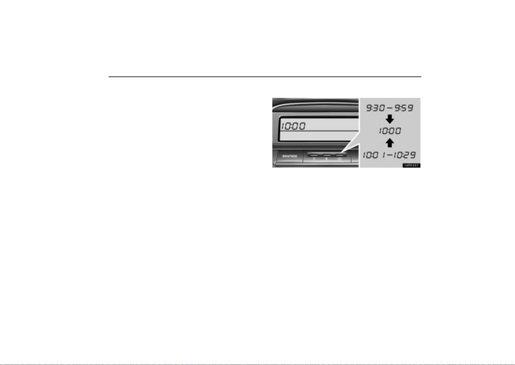
The digital clock indicates the time with the ignition key at
the “ACC” or “ON” position. T o reset the hour, press the
“H” button. To reset the minutes, press the “M” button.
To adjust the time to the nearest hour, press the “:00”
button.
For example, if the “:00” button is pressed when the time is
between 9:30 — 9:59 or between 10:01 — 10:29, the time will
change to 10:00.
When the instrument panel lights are turned on, the brightness
of the display will be reduced.
113
Page 35
INTERIOR EQUIPMENT
You can adjust the brightness of the display. To adjust the
brightness, see “Multi-display light control” on page 105.
If the electrical power source has been disconnected from the
clock, the time display will automatically be set to 1:00 (one
o’clock).
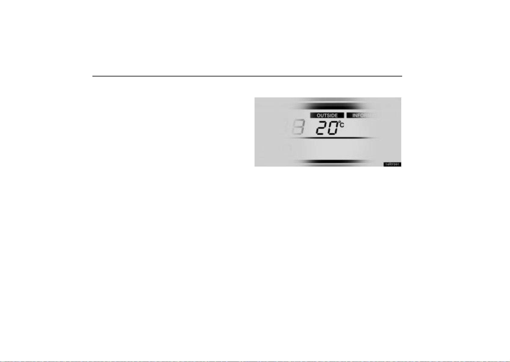
OUTSIDE TEMPERATURE DISPLAY
This display shows the outside temperature when the
ignition switch is on.
The displayed temperature ranges from -30C (-22F) up to
50C (122F). If the temperature does not appear on the
display or it shows “--”, take your vehicle to your Lexus dealer.
When the instrument panel lights are turned on, the brightness
of the display will be reduced.
You can adjust the brightness of the display. To adjust the
brightness, see “Multi-display light control” on page 105.
114
Page 36
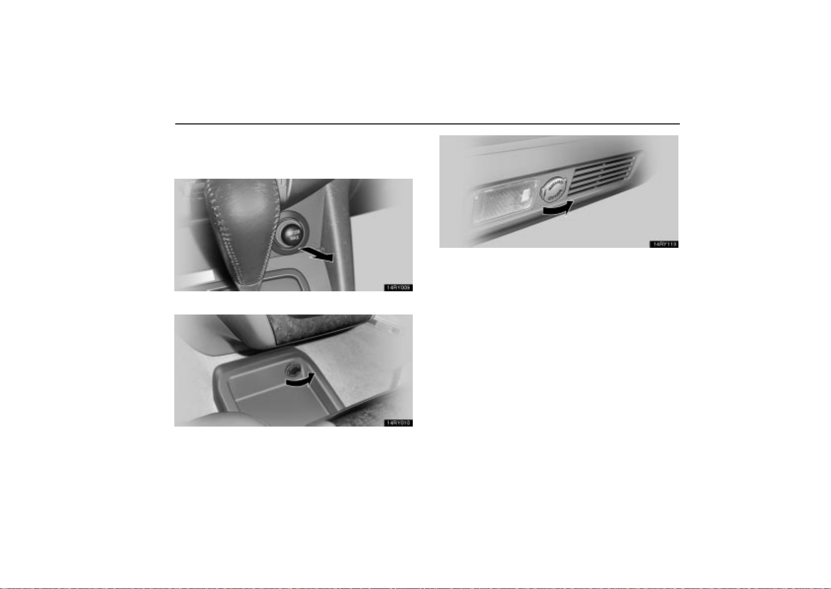
POWER OUTLETS
12 VDC
On the center cluster
INTERIOR EQUIPMENT
In the luggage compartment
The power outlets are designed for power supply for car
accessories.
The ignition key must be in the “ACC” or “ON” position for the
power outlets to be used.
On the tray under the rear console box
115
Page 37
INTERIOR EQUIPMENT
NOTICE
To prevent the fuse from being blown, do not use the
electricity over the total vehicle capacity of 12V/120W
(all the outlets together).
To prevent the battery from being discharged, do not
use the power outlets longer than necessary when
the engine is not running.
Close the power outlet lids when the power outlets
are not in use. Inserting anything other than an
appropriate plug that fits the outlet, or allowing any
liquid into the outlet may cause electrical failure or
short circuits.
116
Page 38
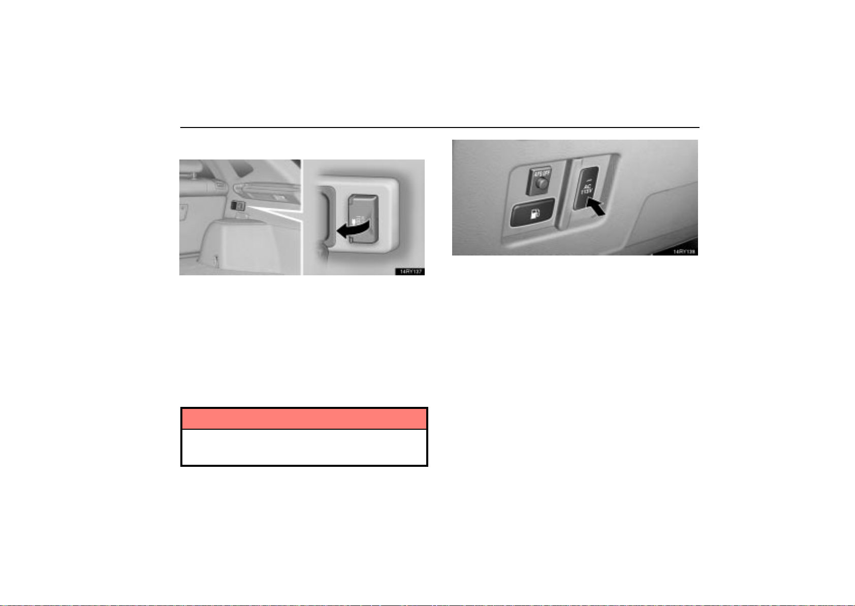
115 VAC
This power outlet is designed for use as a power supply
for the audio device connected to the input terminal
adapter.
The key must be in the “ON” position for the power outlet to be
used.
The maximum capacity for this power outlet is 115 VAC/100W.
If you attempt to use an appliance that requires more than 115
VAC or 100W, the protection circuit will activate and cut the
power supply. The power supply will restart automatically
when you use an appliance that operates within the 115
V AC/100W limits.
INTERIOR EQUIPMENT
Main switch
To use the power outlet, push the main switch on the
instrument panel.
An indicator light will illuminate to indicate that the power outlet
is ready for use.
Push the main switch once again to turn the power outlet off.
When the power outlet is not in use, make sure that the main
switch is turned off.
NOTICE
To prevent the battery from being discharged, do not
use the power outlet longer than necessary when the
engine is not running.
117
Page 39
INTERIOR EQUIPMENT
Close the power outlet lid when the power outlet is
not in use. Inserting a foreign object other than the
appropriate plug that fits the outlet may cause
electrical failure or short circuit.
The power outlet is not designed for the following electric
appliances even though their power consumption is
under 115 VAC/100W. These appliances may not operate
properly.
Appliances with high initial peak wattage: Cathode-ray
tube type televisions, compressor-driven refrigerators,
electric pumps, electric tools, etc.
Measuring devices which process precise data: Medical
equipment, measuring instruments, etc.
Other appliances requiring an extremely stable power
supply: Microcomputer-controlled electric blankets, touch
sensor lamps, etc.
Certain electrical appliances may cause radio noise.
REAR CONSOLE BOX
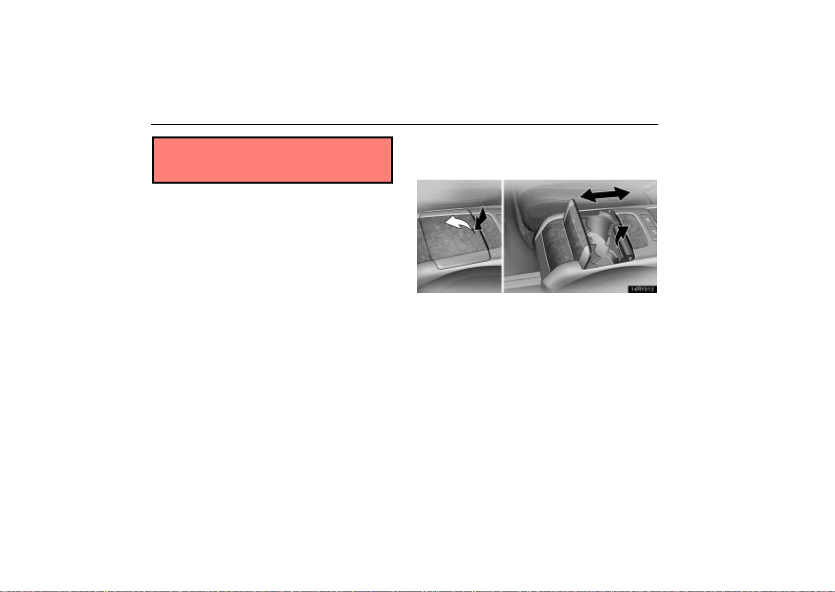
Sliding the rear console box
To slide the rear console box:
1. Open the cupholder lid in the front part of the rear
console box.
2. Slide the rear console box forward or backward while
gripping the lock release lever in the cupholder.
3. Release the lock release lever after sliding the rear
console box to the desired position. Then make sure it is
securely locked in position.
118
Page 40
INTERIOR EQUIPMENT
CAUTION
Do not slide the rear console box while the vehicle is
moving. Doing so may cause the driver to mishandle
the vehicle and an accident may occur resulting in
death or serious injuries.
Be careful not to get hands or feet pinched between
the rear console box and the center cluster or rear
seat.
Be careful not to hit any passengers with the rear
console box while sliding it.
After sliding the rear console box, make sure it is
securely locked in position.
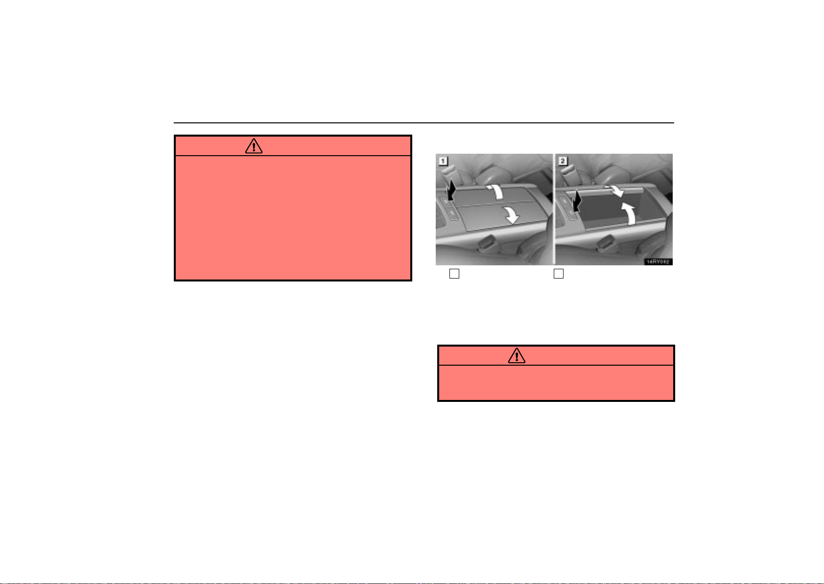
Using the rear console box
1
Open
To open the rear console box, push the “OPEN” button.
The rear console box light comes on when the tail lights are
turned on.
To close the rear console box, push the “CLOSE” button.
2
Close
CAUTION
To reduce the chance of injury in case of an accident or
a sudden stop, always keep the rear console box closed
while driving.
119
Page 41
INTERIOR EQUIPMENT
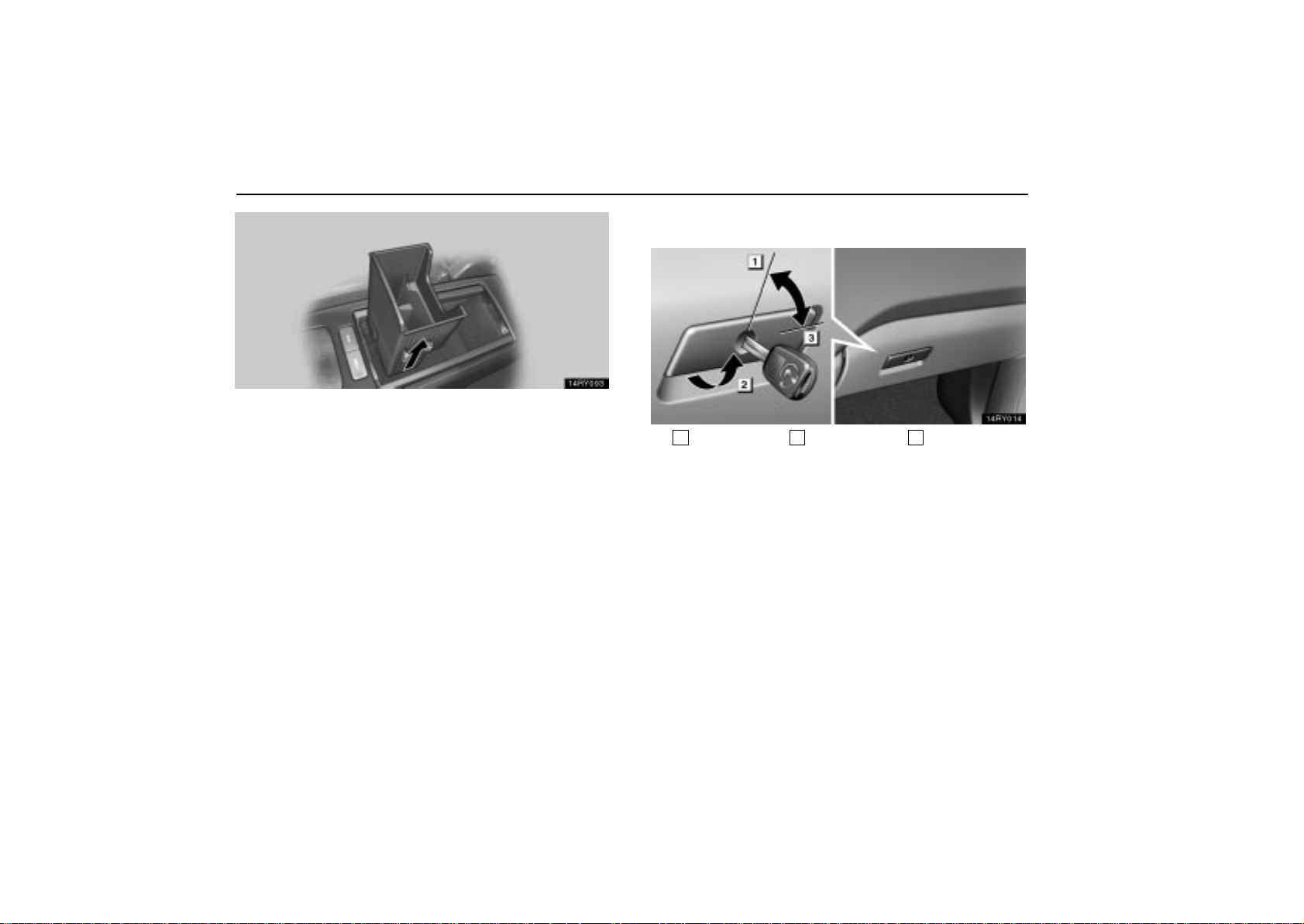
To remove the adapter tray inside the box, pull it up.
GLOVE BOX
120
1
Unlock
To open the glove box door, pull the lever. To lock the
glove box door, insert the master key and turn it
clockwise.
With the ta i l l i g h t s o n , t h e g l ove box light will come on when the
glove box door is open.
The power back door off switch is installed inside the glove box.
See page 42 for further information.
2
Open
3
Lock
Page 42
INTERIOR EQUIPMENT
CAUTION
To reduce the chance of injury in case of an accident or
a sudden stop, always keep the glove box door closed
while driving.
GARAGE DOOR OPENER
The garage door opener (
Transceiver) is manufactured under license from
HomeLink
and can be programmed to operate garage
doors, gates, entry doors, door locks, home lighting
systems, and security systems, etc.
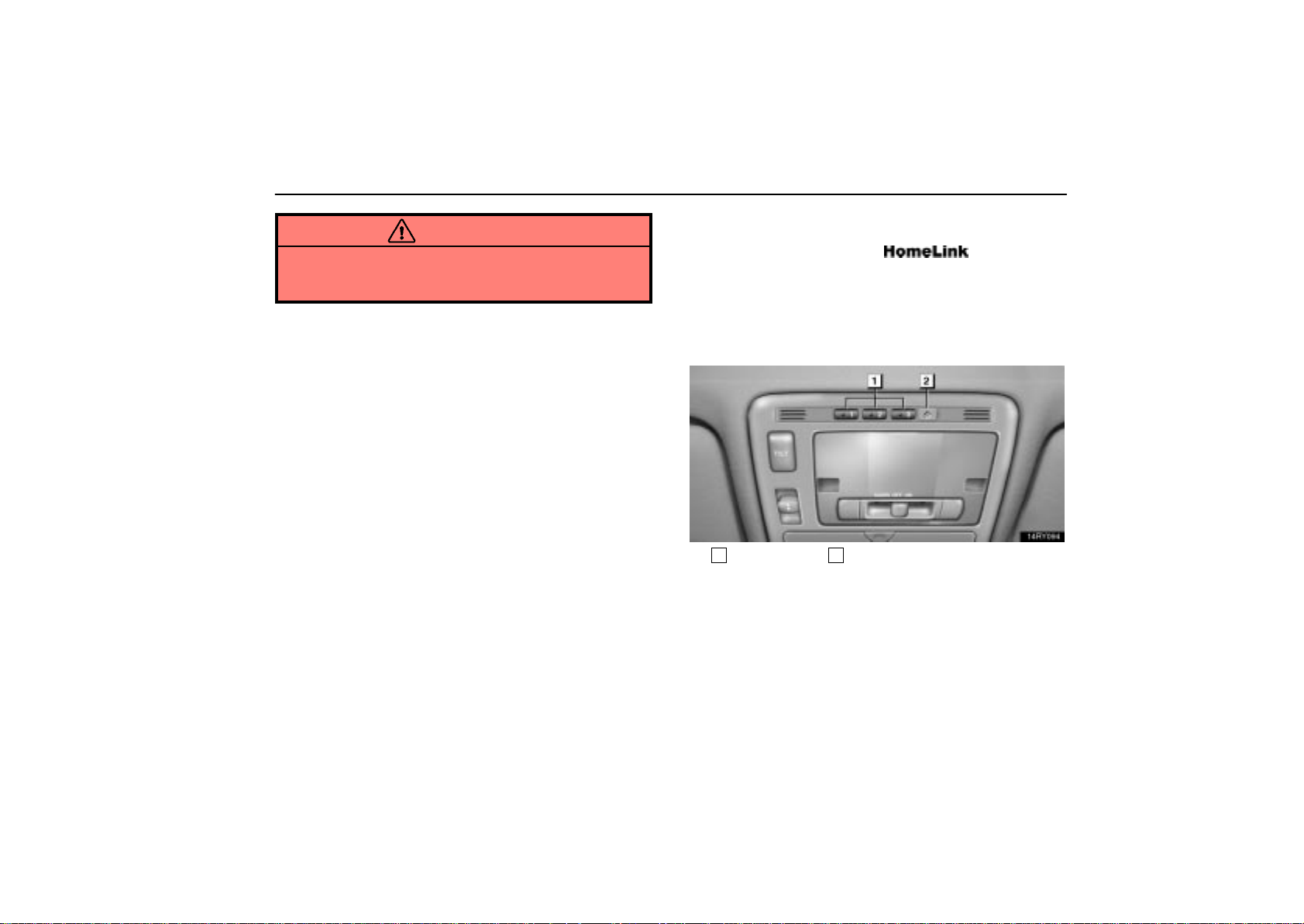
(a) Programming the HomeLink
1
Buttons
The HomeLink in your vehicle has 3 buttons and you can
store one program for each button.
To ensure correct programming into the HomeLink
new battery in the hand-held transmitter prior to programming.
2
Indicator light
Universal
, install a
121
Page 43

INTERIOR EQUIPMENT
The battery side of the hand-held transmitter must be pointed
away from the HomeLink
during the programming process.
For Canadian users, follow the procedure in “Programming an
entrance gate/programming all devices in the Canadian
market”.
1. Decide which of 3 HomeLink
2. Place your hand-held garage transmitter 25 to 75 mm (1 to
3 in.) away from the surface of the HomeLink
Keep the indicator light on the HomeLink
buttons you want to program.
.
in view while
programming.
3. Simultaneously press and hold the hand-held garage
transmitter button along with the selected HomeLink
button.
4. When the indicator light on the HomeLink changes from a
slow to a rapid flash after 20 seconds, you can release both
buttons.
5. Test the operation of the HomeLink
by pressing the newly
programmed button. If programming a garage door opener,
check to see if the garage door opens and closes.
If the garage door does not operate, identify if your garage
transmitter is of the “Rolling Code” type. Press and hold the
programmed HomeLink
rolling code feature if the indicator light (on the HomeLink
button. The garage door has the
flashes rapidly and then remains lit after 2 seconds. If your
garage transmitter is the “Rolling Code” type, proceed to the
heading “Programming a rolling code system”.
6. Repeat steps 2 through 5 for each remaining HomeLink
button to program another device.
Programming a rolling code system
If your device is “Rolling Code” equipped, it is necessary
to follow steps 1 through 4 under the heading
“Programming the HomeLink
the steps listed below.
1. Locate the “training” button on the ceiling mounted garage
door opener motor. The exact location and color of the button
may vary by brand of garage door opener. Refer to the owner’s
guide supplied by the garage door opener manufacturer for the
location of this “training” button.
2. Press the “training” button on the ceiling mounted garage
door opener motor.
Following this step, you have 30 seconds in which to initiate
step 3 below.
” before proceeding with
)
122
Page 44

INTERIOR EQUIPMENT
3. Press and release the vehicle’s programmed HomeLink
button twice. The garage door may open. If the door does
open, the programming process is complete. If the door does
not open, press and release the button a third time. This third
press and release will complete the programming process by
opening the garage door.
The ceiling mounted garage door opener motor should now
recognize the HomeLink
unit and be able to activate the
garage door up/down.
4. Repeat steps 1 through 3 for each remaining HomeLink
button to program another rolling code system.
Programming an entrance gate/programming
all devices in the Canadian market
1. Decide which of the 3 HomeLink buttons you want to
program.
2. Place your hand-held gate/device transmitter 25 to 75 mm
(1 to 3 in.) away from the surface of the HomeLink
Keep the indicator light on the HomeLink in view while
programming.
3. Press and hold the selected HomeLink
button.
.
4. Continuously press and release (cycle) the hand-held
gate/device transmitter button every two seconds until step 5
is complete.
5. When the indicator light on the HomeLink
changes from a
slow to a rapid flash after 20 seconds, you can release both
buttons.
6. Test the operation of the HomeLink
by pressing the newly
programmed button. Check to see if the gate/device operates
correctly.
7. Repeat steps 1 through 6 for each remaining HomeLink
button to program another device.
Programming other devices
To program other devices such as home security systems,
home door locks or lighting, contact your authorized Lexus
dealer for assistance.
Reprogramming a button
Individual HomeLink
reprogram a single button, follow the procedure “Programming
the HomeLink
buttons cannot be erased, however, to
”.
123
Page 45
INTERIOR EQUIPMENT
(b) Operating the HomeLink
To operate the HomeLink, press the appropriate HomeLink
button to activate the programmed device. The HomeLink
indicator light should come on. The HomeLink continues to
send the signal for up to 20 seconds as long as the button is
pressed.
(c) Erasing the entire HomeLink memory (all
three programs)
To erase all previously programmed codes at one time, press
and hold down the 2 outside buttons for 20 seconds until the
indicator light flashes.
If you sell your vehicle, be sure to erase the programs stored
in the HomeLink
memory.
When programming the HomeLink Universal
CAUTION
Transceiver, you may be operating a garage door or
other device. Make sure people and objects are out
of the way of the garage door or other device to
prevent potential harm or damage.
Do not use this HomeLink
Universal Transceiver
with any garage door opener that lacks the safety
stop and reverse feature as required by federal safety
standards. (This includes any garage door opener
model manufactured before April 1, 1982.) A garage
door opener which cannot detect an object (signaling
the door to stop and reverse), does not meet current
federal safety standards. Using a garage door
opener without these features increases risk of
serious injury or death.
124
Page 46
INTERIOR EQUIPMENT
This device complies with Part 15 of the FCC Rules
and with RSS- 210 of the IC Rules. Operation is
subject to the following two conditions: (1) This
device may not cause harmful interference, and (2)
this device must accept any interference received,
including interference that may cause undesired
operation.
WARNING: This transmitter has been tested and
complies with FCC and IC rules. Changes or
modifications not expressly approved by the
party responsible for compliance could void the
user’s authority to operate the device.
CUPHOLDERS
Front
On the instrument panel
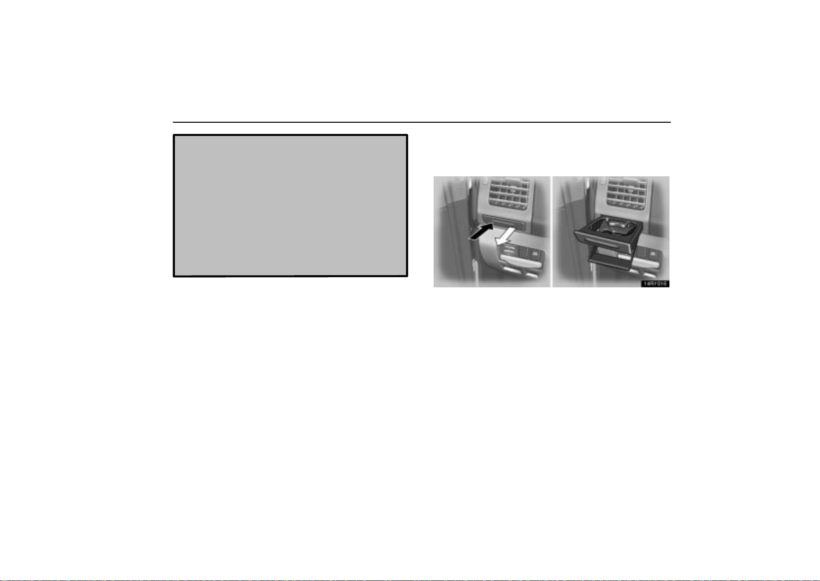
To use the cupholder, push in the cupholder portion
located on the instrument panel.
The cupholder is designed for holding cups or drink-cans
securely.
125
Page 47
INTERIOR EQUIPMENT
In the front part of the rear console box
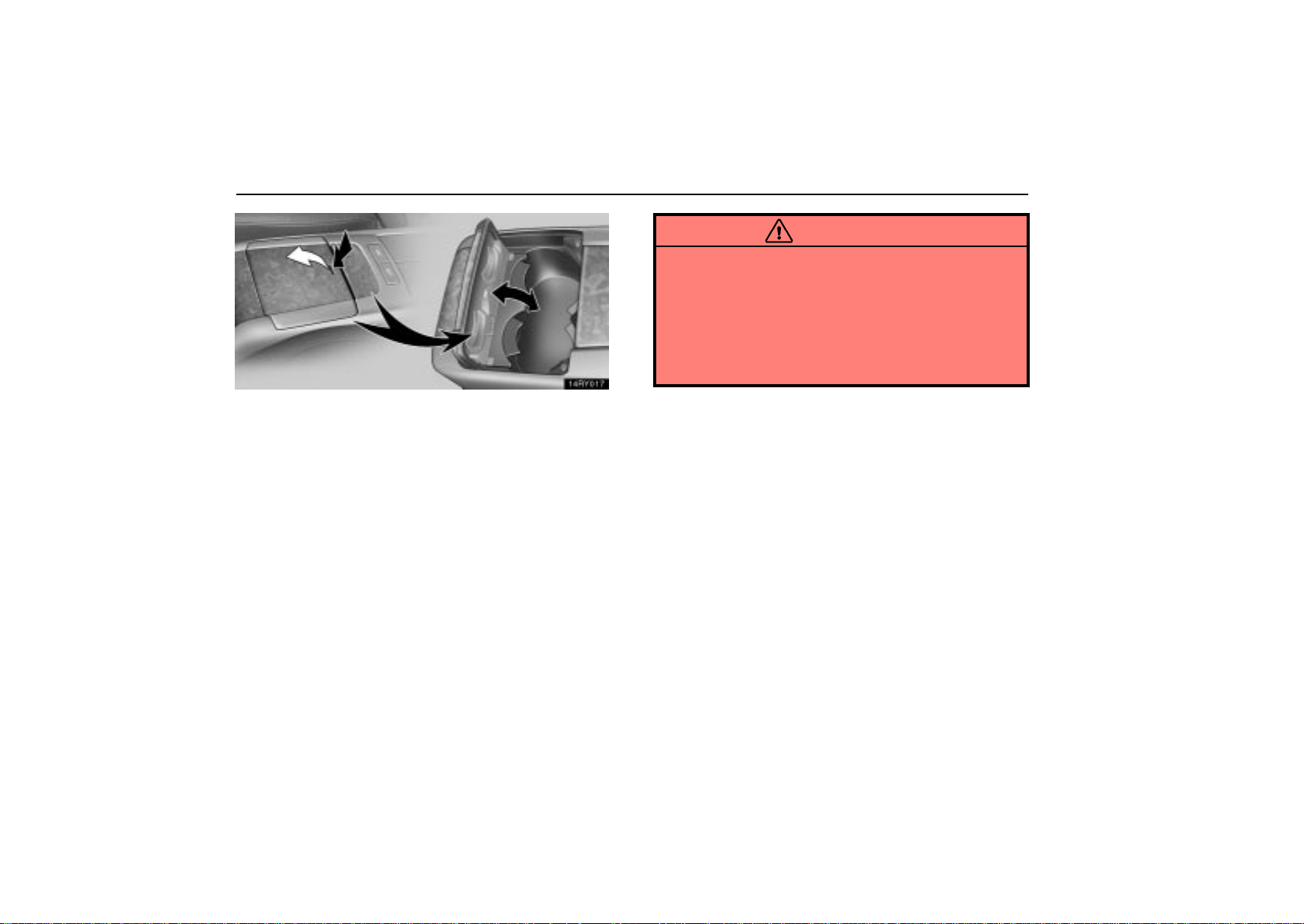
To use the cupholder, push the cupholder lid.
The cupholder is designed for holding cups or drink-cans
securely.
The cupholder can be adjusted to the size of the cups by
altering the arm position.
The cupholder light comes on when the tail lights are turned on.
CAUTION
Do not place anything else other than cups or
drink-cans in the cupholder, as such items may be
thrown about in the compartment and possibly injure
people in the vehicle during sudden braking or in an
accident.
To reduce the chance of injury in case of an accident
or sudden stop while driving, keep the cupholder
closed when not in use.
126
Page 48
INTERIOR EQUIPMENT
Rear
Rear seat armrest
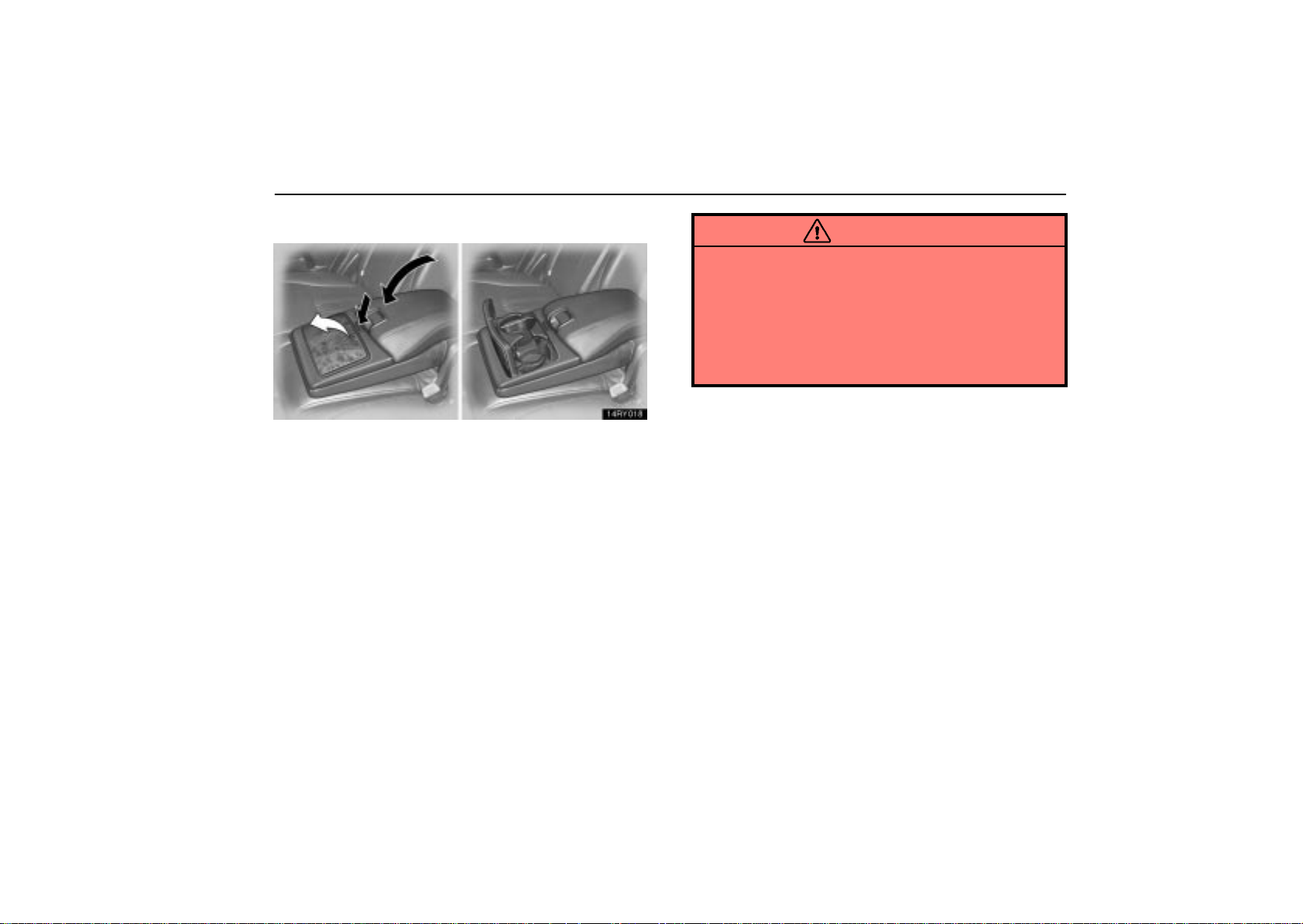
To use the cupholder, pull down the rear seat armrest and
push the button on the armrest.
The cupholder is designed for holding cups or drink-cans
securely.
CAUTION
Do not place anything else other than cups or
drink-cans on the cupholder, as such items may be
thrown about in the compartment and possibly injure
people in the vehicle during sudden braking or in an
accident.
To reduce the chance of injury in case of an accident
or sudden stop while driving, keep the cupholder
closed when not in use.
127
Page 49
INTERIOR EQUIPMENT
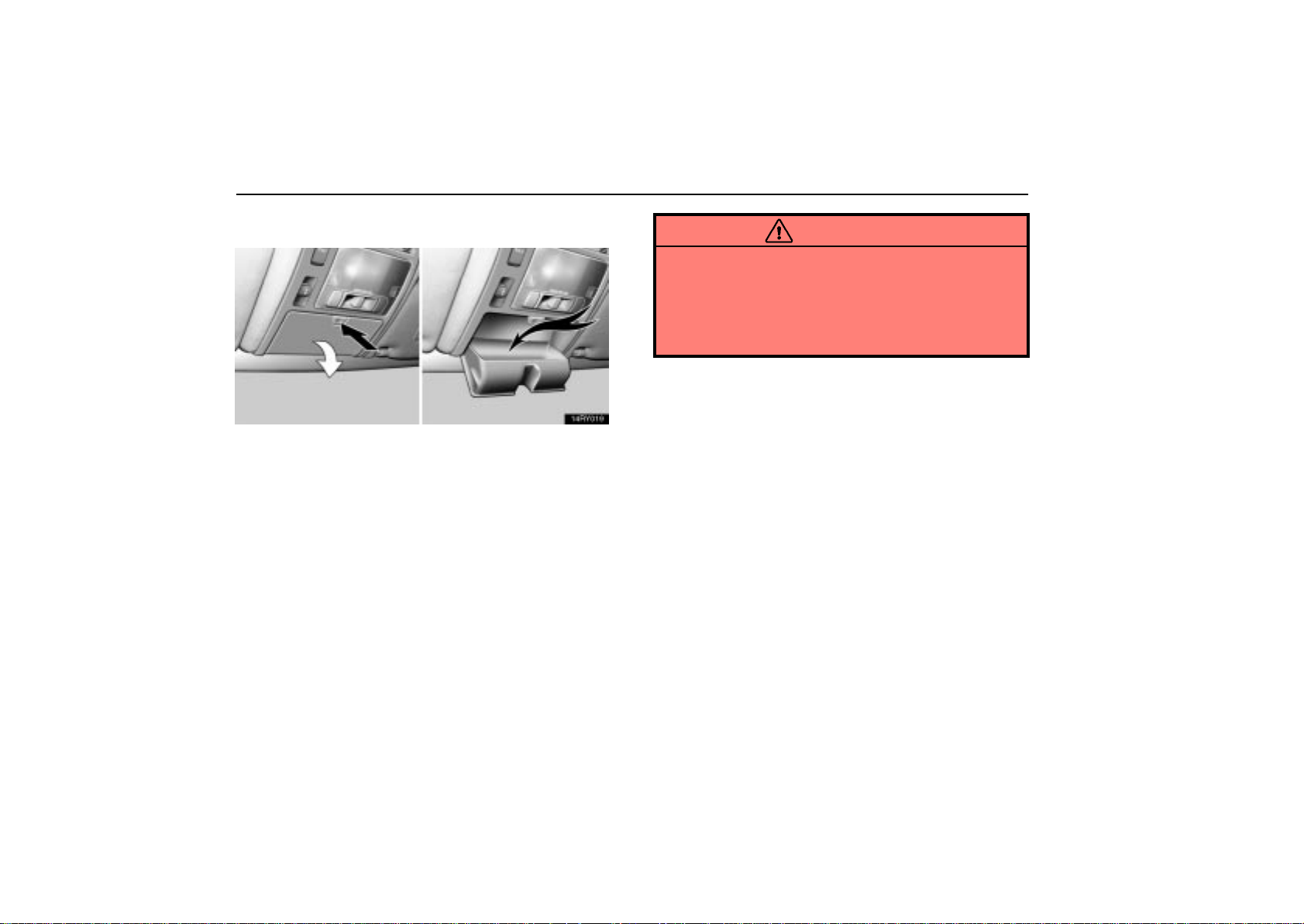
OVERHEAD CONSOLE BOX
To use the overhead console box, push the button.
CAUTION
To reduce the chance of injury in case of an accident
or a sudden stop, always keep the overhead console
box closed while driving.
Do not place any object heavier than 100 g (0.22 lb.)
in it. Heavier objects may cause the box to open and
the contents to fly out resulting in injuries.
128
Page 50
NOTICE
During hot weather, the interior of the vehicle becomes
very hot. Do not leave anything flammable or
deformable such as a lighter, glasses, etc. inside.
INTERIOR EQUIPMENT
129
Page 51
INTERIOR EQUIPMENT
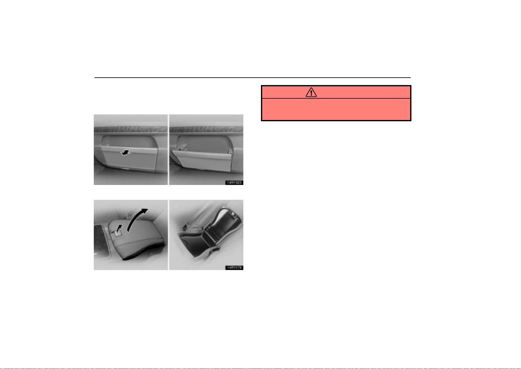
AUXILIARY BOXES
To use the auxiliary boxes, open as shown in the following
illustrations.
On the inner side of the front doors
CAUTION
To reduce the chance of injury in case of an accident or
a sudden stop, always keep the auxiliary box closed
while driving.
130
Rear seat armrest
Page 52
AUXILIARY BOX AND GROCERY
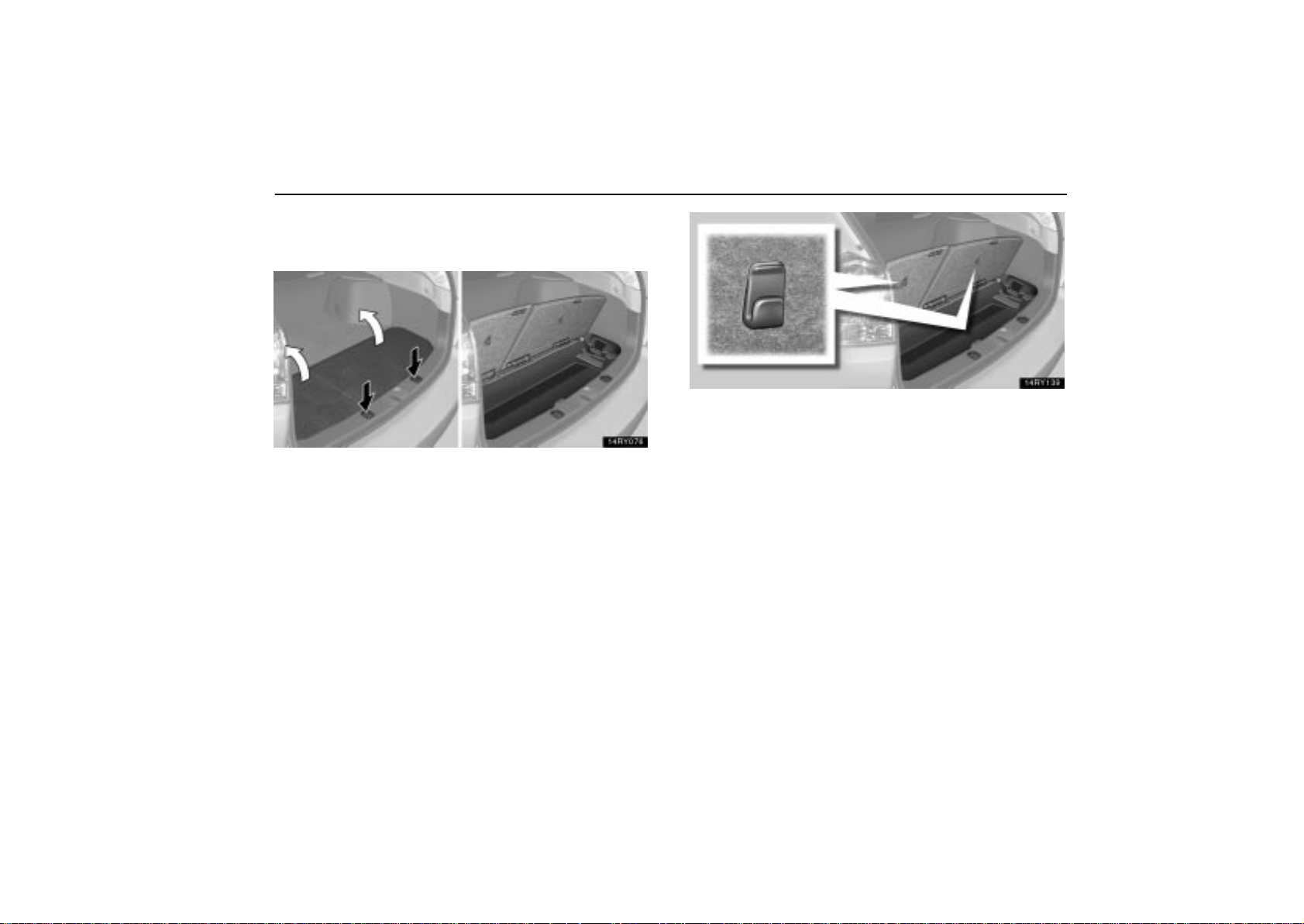
BAG HOOKS
To use the auxiliary box, open it as shown above.
INTERIOR EQUIPMENT
This auxiliary box is equipped with grocery bag hooks.
These hooks are designed for hanging things like grocery
bags.
131
Page 53
INTERIOR EQUIPMENT
CAUTION
Except when using the grocery bag hooks — T o reduce
the chance of injury in case of an accident or a sudden
stop, always keep the auxiliary box closed while driving.
NOTICE
To prevent damage to the hooks, do not hang any object
heavier than 2 kg (4 lb.) on them.
132
Page 54
INTERIOR EQUIPMENT
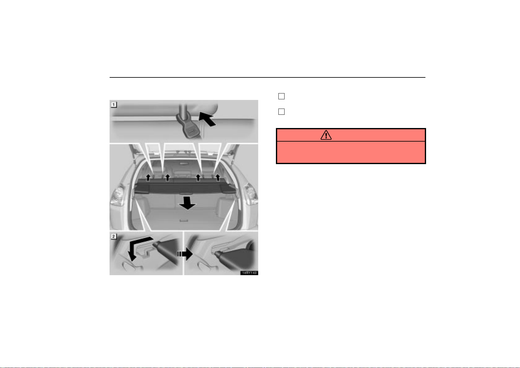
LUGGAGE COVER
To use the luggage cover:
1
Attach the front hooks of the luggage cover to the head
restraints.
2
Pull out the rear luggage cover and hook it onto the
anchors.
CAUTION
Do not place anything on the luggage cover. Such items
may be thrown about and possibly injure people in the
vehicle during sudden braking or a collision.
133
Page 55
INTERIOR EQUIPMENT
Automatic retract function
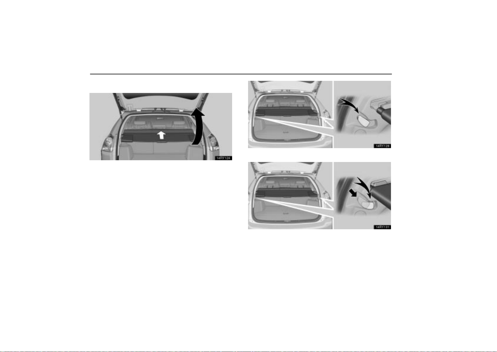
The rear luggage cover is retracted automatically when
the back door is opened.
Active position
Inactive position
134
Page 56
INTERIOR EQUIPMENT
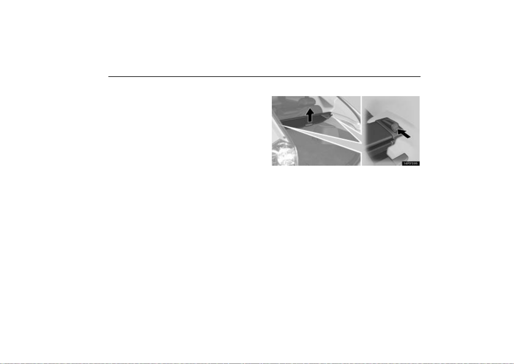
To activate the automatic retract function, place the knobs
in the active position.
If you do not want to activate the automatic retract
function, push the knobs to place the inactive position
while pulling the luggage cover toward you.
To reactivate the automatic retract function, push the
knobs again to return them to the active position.
Removing luggage cover
To remove the luggage cover, lift it up after pushing
forward the lock release knobs on both sides.
135
Page 57
INTERIOR EQUIPMENT
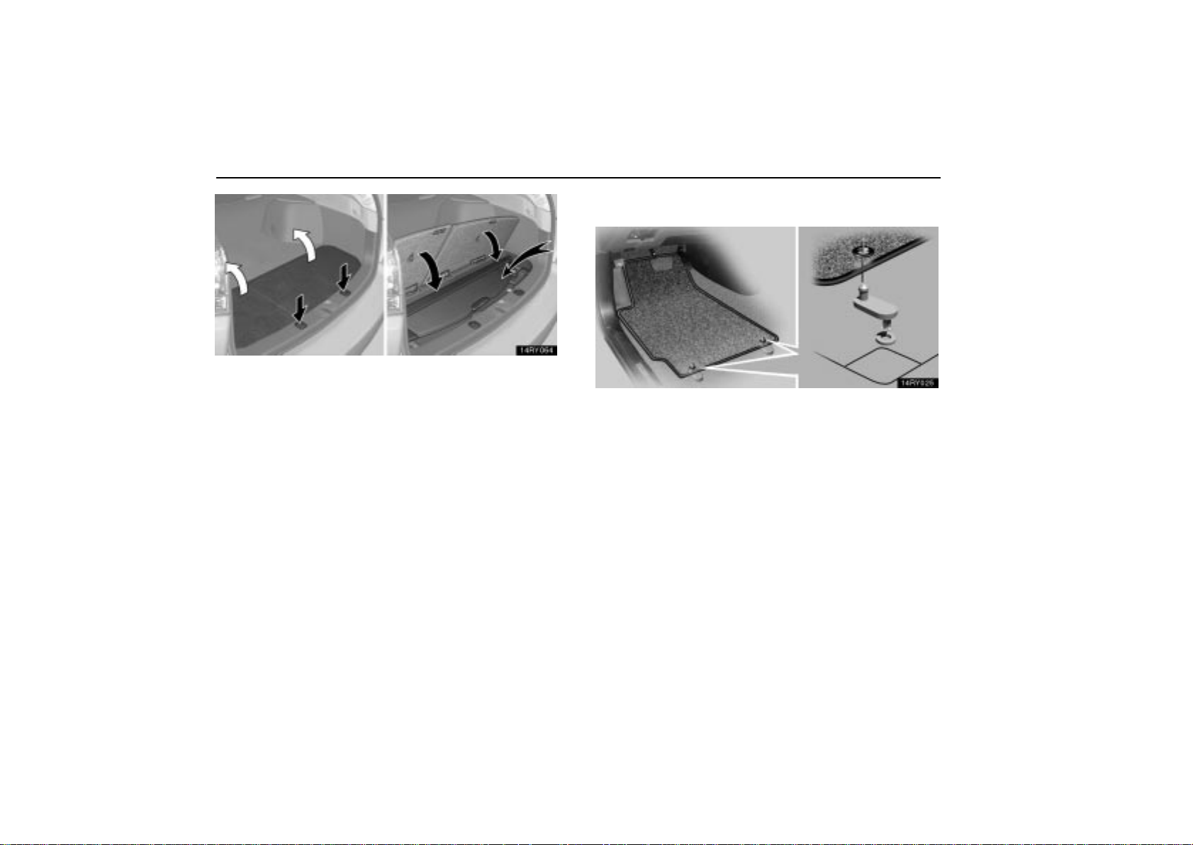
You can stow the luggage cover in the auxiliary box in the
luggage compartment as shown in the illustration.
After removing the luggage cover, stow it in the auxiliary box
or place it somewhere other than the passenger compartment.
This will prevent passengers from being injured in the event of
a sudden stop or accident.
FLOOR MAT
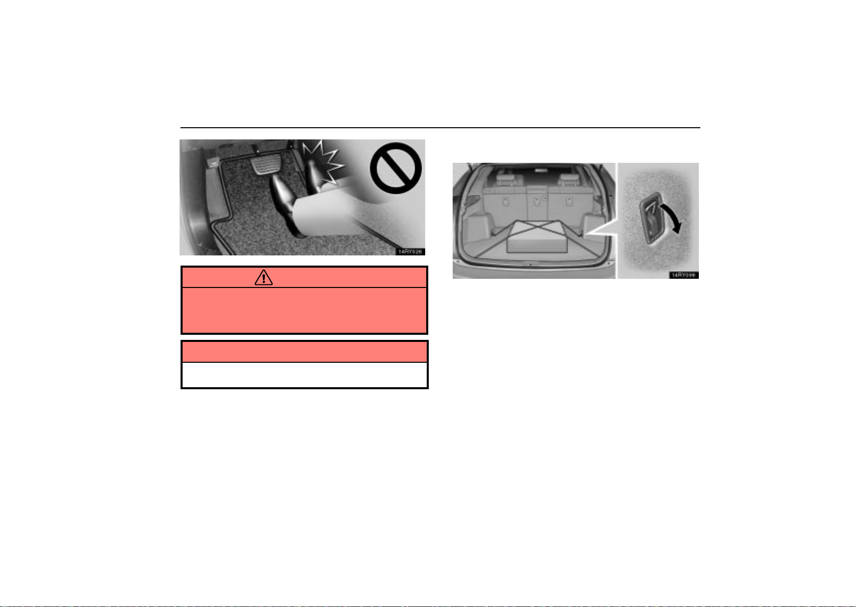
Use a floor mat of the correct size.
If the floor carpet and floor mat have 2 holes, then they are
designed for use with locking clips. Fix the floor mat with
locking clips into the holes in the floor carpet.
136
Page 58
INTERIOR EQUIPMENT
TIE-DOWN HOOKS
CAUTION
Make sure the floor mat is properly placed on the floor
carpet. If the floor mat slips and interferes with the
movement of the pedals during driving, it may cause an
accident.
NOTICE
Do not use the anchor brackets on the back of the rear
seatback instead of the tie-down hooks.
To secure your luggage, use the tie-down hooks as shown
above.
See “Stowage precautions” on page 546 for precautions when
loading luggage.
137
Page 59

INTERIOR EQUIPMENT
138
Page 60

SECTION 1 –
INSTRUMENTS AND CONTROLS
Exterior equipment
Hood 140. . . . . . . . . . . . . . . . . . . . . . . . . . . . . . . . . . . . . . . . . . . . . . . . . . . . . . . . . . . . . . . . . . . . . . . . . . . . .
Fuel tank cap 141. . . . . . . . . . . . . . . . . . . . . . . . . . . . . . . . . . . . . . . . . . . . . . . . . . . . . . . . . . . . . . . . . . . . . .
Moon roof (normal type) 144. . . . . . . . . . . . . . . . . . . . . . . . . . . . . . . . . . . . . . . . . . . . . . . . . . . . . . . . . . . . .
Moon roof (multi–panel type) 148. . . . . . . . . . . . . . . . . . . . . . . . . . . . . . . . . . . . . . . . . . . . . . . . . . . . . . . . .
Roof luggage carrier 153. . . . . . . . . . . . . . . . . . . . . . . . . . . . . . . . . . . . . . . . . . . . . . . . . . . . . . . . . . . . . . . .
5
139
Page 61
EXTERIOR EQUIPMENT
HOOD
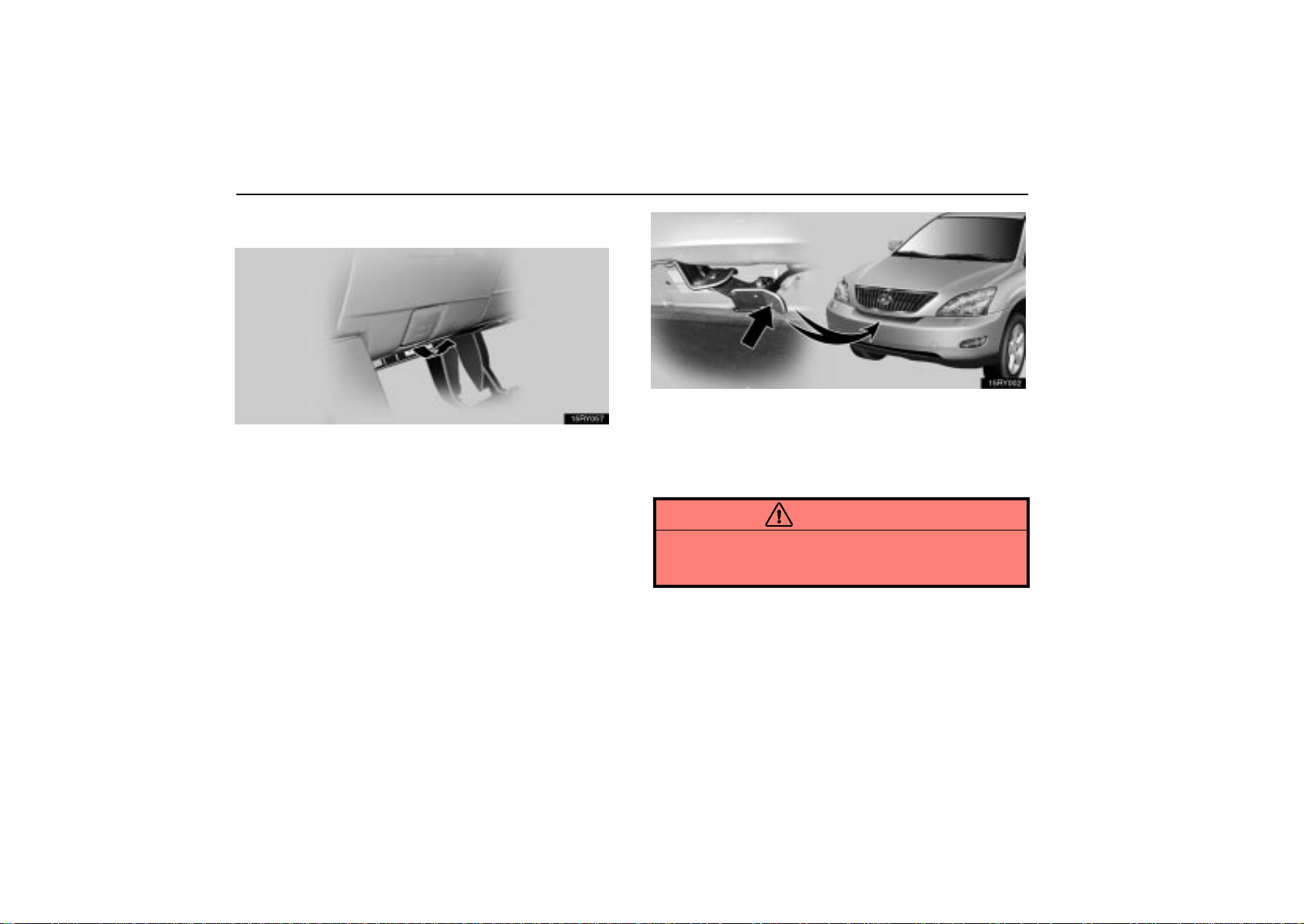
1. To open the hood, pull the hood lock release lever under
the driver–side instrument panel. The hood will spring up
slightly.
2. Insert your fingers under the hood, push up the
auxiliary catch lever and lift the hood.
Before closing the hood, check to see that you have not
forgotten any tools, rags, etc. Then lower the hood and make
sure it locks.
CAUTION
Before driving, be sure that the hood is closed and
securely locked. Otherwise, the hood may open
unexpectedly while driving and an accident may occur.
140
Page 62
FUEL TANK CAP
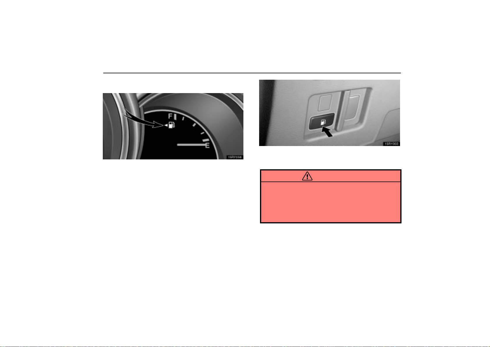
This indicates that the fuel filler door is on the left side of
your vehicle.
EXTERIOR EQUIPMENT
1. To open the fuel filler door, push the switch.
When refueling, turn off the engine.
CAUTION
Do not smoke, cause sparks or allow open flames
when refuelling. The fumes are flammable.
When opening the cap, do not remove the cap
quickly. In hot weather, fuel under pressure could
cause injury by spraying out of the filler neck if the
cap is suddenly removed.
141
Page 63
EXTERIOR EQUIPMENT
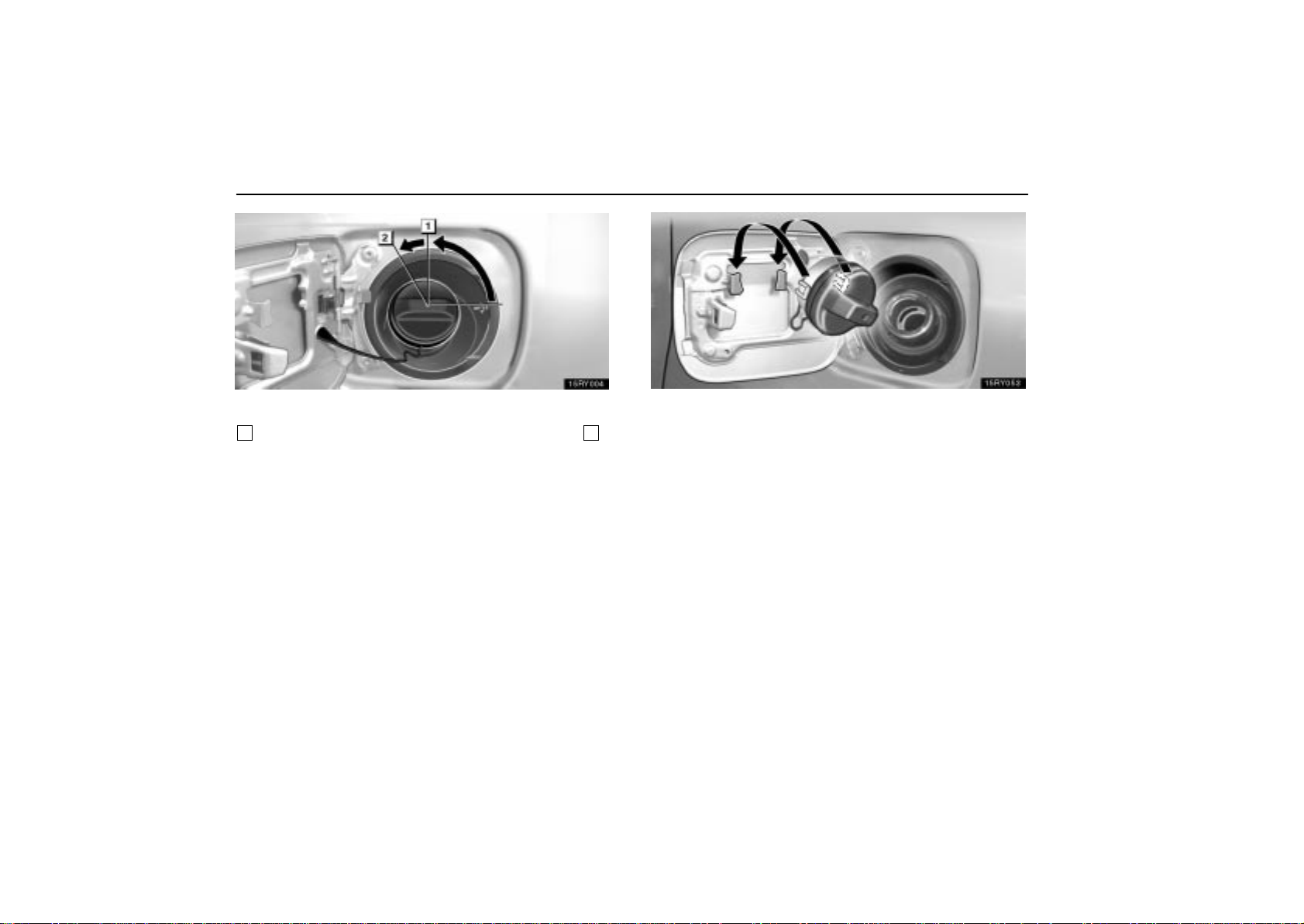
2. To remove the fuel tank cap, turn the cap
counterclockwise by 90 degrees (to the pressure point
1
), and then turn it a additional 30 degrees (to point 2).
Pause slightly before removing it.
It is not unusual to hear a slight swoosh when the cap is
opened.
142
3. The removed cap can be stored on the back side of the
fuel filler door.
Position the cap so that the hooks point to the left and right, and
set it in the receptacle on the back side of the door.
When installing the cap, turn the cap clockwise until you
hear a click. When you hear the click, the cap is fully
closed.
If the cap is not tightened securely, the malfunction indicator
lamp comes on. Make sure the cap is tightened securely.
The indicator lamp goes off after driving several times. If the
indicator lamp does not go off, contact your Lexus dealer as
soon as possible.
Page 64
CAUTION
Make sure the cap is installed securely to prevent fuel
spillage in the event of an accident.
Use only a genuine Lexus fuel tank cap for
replacement. It is designed to regulate fuel tank
pressure.
NOTICE
To prevent damage to the cap, apply force only in the
turning direction to the cap. Do not pull or pry it.
EXTERIOR EQUIPMENT
143
Page 65
EXTERIOR EQUIPMENT
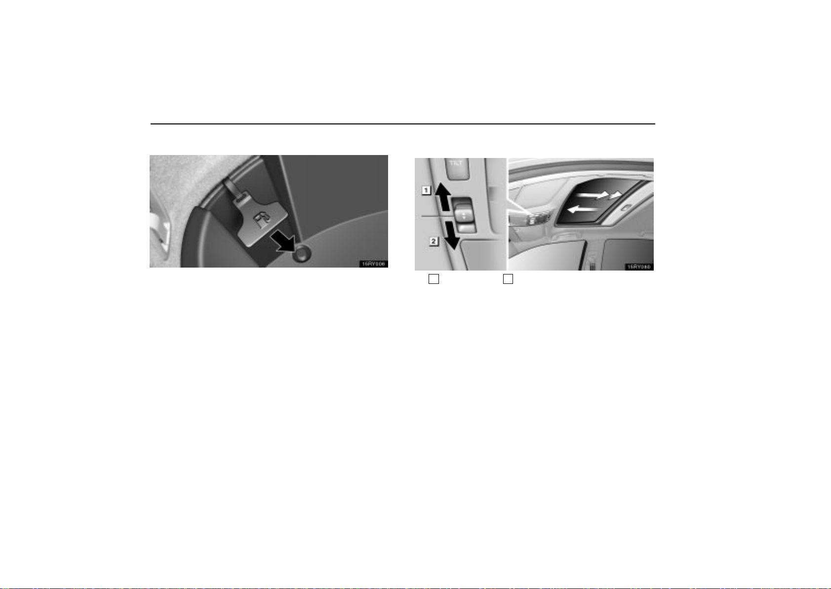
In case the opener is not actuated
Open the auxiliary box in the luggage compartment, pull
the manual lever.
This is used in case the fuel filler door cannot be opened due
to a discharged battery or other trouble.
MOON ROOF (normal type)
1
Open
To slide open the moon roof, push the slide control switch
toward the back. The moon roof will open and stop
partway 45 mm (1.8 in.) from the fully opened position.
When you push the switch once again, the moon roof will
fully open. T o stop partway, push either side of the slide
control switch.
As driving with the moon roof opened fully will cause wind
throbs, we recommend you to drive with the moon roof partway
45 mm (1.8 in.) from the fully opened position.
2
Close
144
Page 66
The sunshade can be opened or closed manually. However,
if you open the moon roof, the sunshade will be opened with
the moon roof.
To close the moon roof, push the slide control switch
toward the front. The moon roof will fully close. To stop
partway, push the either side of the slide control switch.
EXTERIOR EQUIPMENT
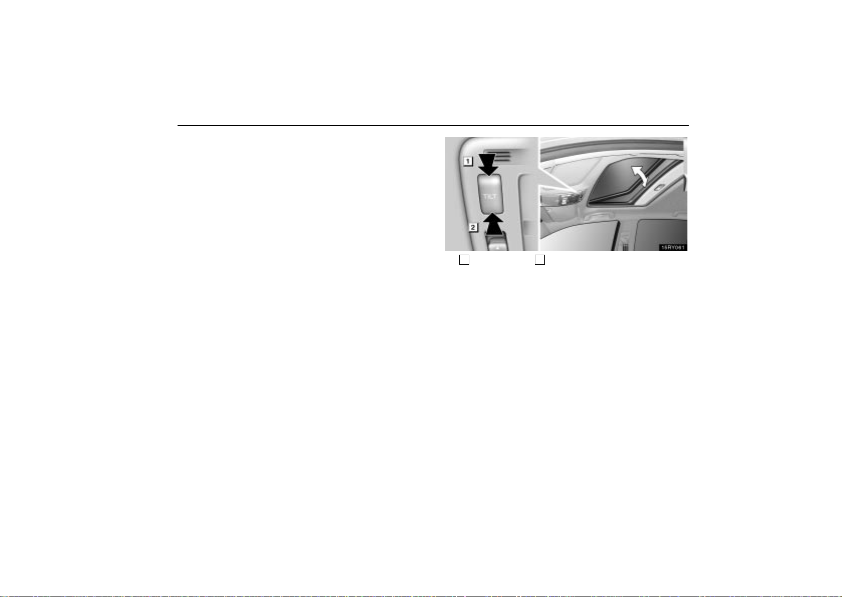
1
Tilt up
2
Tilt down
To tilt up the moon roof, push the “TILT” switch on the rear
side. The moon roof will fully tilt up. T o stop partway, push
either side of the “TILT” switch.
To tilt down the moon roof, push the “TILT” switch on the
front side. The moon roof will fully tilt down. To stop
partway, push either side of the “TILT” switch.
145
Page 67
EXTERIOR EQUIPMENT
To operate the moon roof, the ignition key must be in the “ON”
position.
If the moon roof is left open when you turn the ignition key to
the “ACC” or “LOCK” position and open the driver’s door, a
buzzer will remind you to close the moon roof.
Retained accessory power operation: Even if the ignition
key is turned to the “ACC” or “LOCK” position, the moon roof
can be operated until either front door is opened (or for 43
seconds).
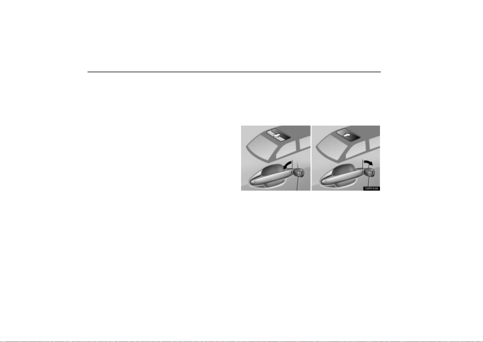
Operating the moon roof from outside the
vehicle
The moon roof can be operated using an ignition key.*
NOTE:
* This feature can be deactivated.
Ask your Lexus dealer for details.
Close
Insert the ignition key into the key hole on the driver’s
door.
Open
146
Page 68
EXTERIOR EQUIPMENT
To close the moon roof: Turn the key in the locking direction
and hold it.
After the doors are locked, the moon roof begins to close. To
stop in the middle, return the key.
To open the moon roof: Turn the key in the unlocking
direction and hold it.
After the door is unlocked, the moon roof begins to open. To
stop in the middle, return the key.
The moon roof also can be opened using the wireless remote
control. For details, see page 25.
Jam protection function
If something gets caught between the moon roof and frame
during slide closing operation, the moon roof stops and
opens half way.
If something gets caught between the moon roof and frame
during tilting down operation, the moon roof stops and
opens fully.
If the moon roof receives a strong impact, this function may
work even if nothing is caught.
If the battery is disconnected or run down
The moon roof may not operate automatically and the jam
protection function will not function correctly after you
reconnect, replace or recharge the battery. In any of these
cases, you should normalize the moon roof.
To normalize the moon roof, push and hold the slide control
switch toward the front or “TILT” switch on the rear side. The
moon roof will tilt up and down, then slide open and close. After
the slide close operation, release the switch.
Make sure that the moon roof opens and closes automatically.
If the moon roof cannot be operated properly, have it checked
by your Lexus dealer.
CAUTION
To avoid serious personal injury, you must do the
following.
While the vehicle is moving, always keep the heads,
hands and other parts of the bodies of all occupants
away from the roof opening. Otherwise, they could
be seriously injured if the vehicle stops suddenly or
if the vehicle is involved in an accident.
147
Page 69
EXTERIOR EQUIPMENT
Before you close the moon roof, always make sure
there is nobody around the moon roof. You must also
make sure nobody places his or her head, hands and
other parts of the body in the roof opening. If
someone’s neck, head or hands get caught in the
closing roof, it could result in a serious injury. When
anyone closes the moon roof, first make sure it is safe
to do so.
Be sure to remove the ignition key when you leave
your vehicle.
Never leave anyone (particularly a small child) alone
in your vehicle, especially with the ignition key still
inserted. Otherwise, he/she could use the moon roof
switches and get trapped in the roof opening.
Unattended person (particularly a small child) can be
involved in a serious accident.
Never sit on top of the vehicle around the roof
opening.
Never try jamming any part of your body to activate
the jam protection function intentionally.
The jam protection function may not work if
something gets caught just before the moon roof is
fully closed.
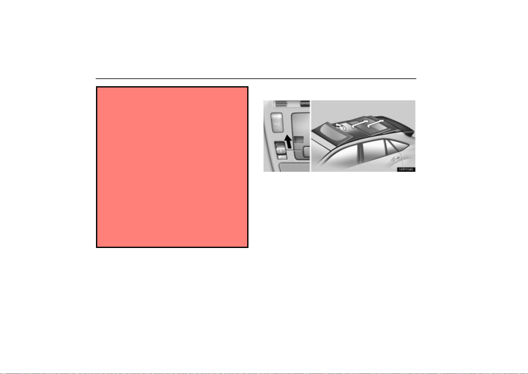
MOON ROOF (multi–panel type)
To open the moon roof, push the slide control switch
toward the back. The front panel tilts up and the center
and rear panels fully open. To stop partway, push either
side of the slide control switch or the “TILT” switch briefly.
The sunshade can be opened or closed manually. However,
if you open the moon roof, the sunshade will be opened with
the moon roof.
Before opening the moon roof , ma ke sure the radio antenna is
in the lock position. Otherwise, the antenna may get caught
between the moon roof and frame.
148
Page 70
EXTERIOR EQUIPMENT
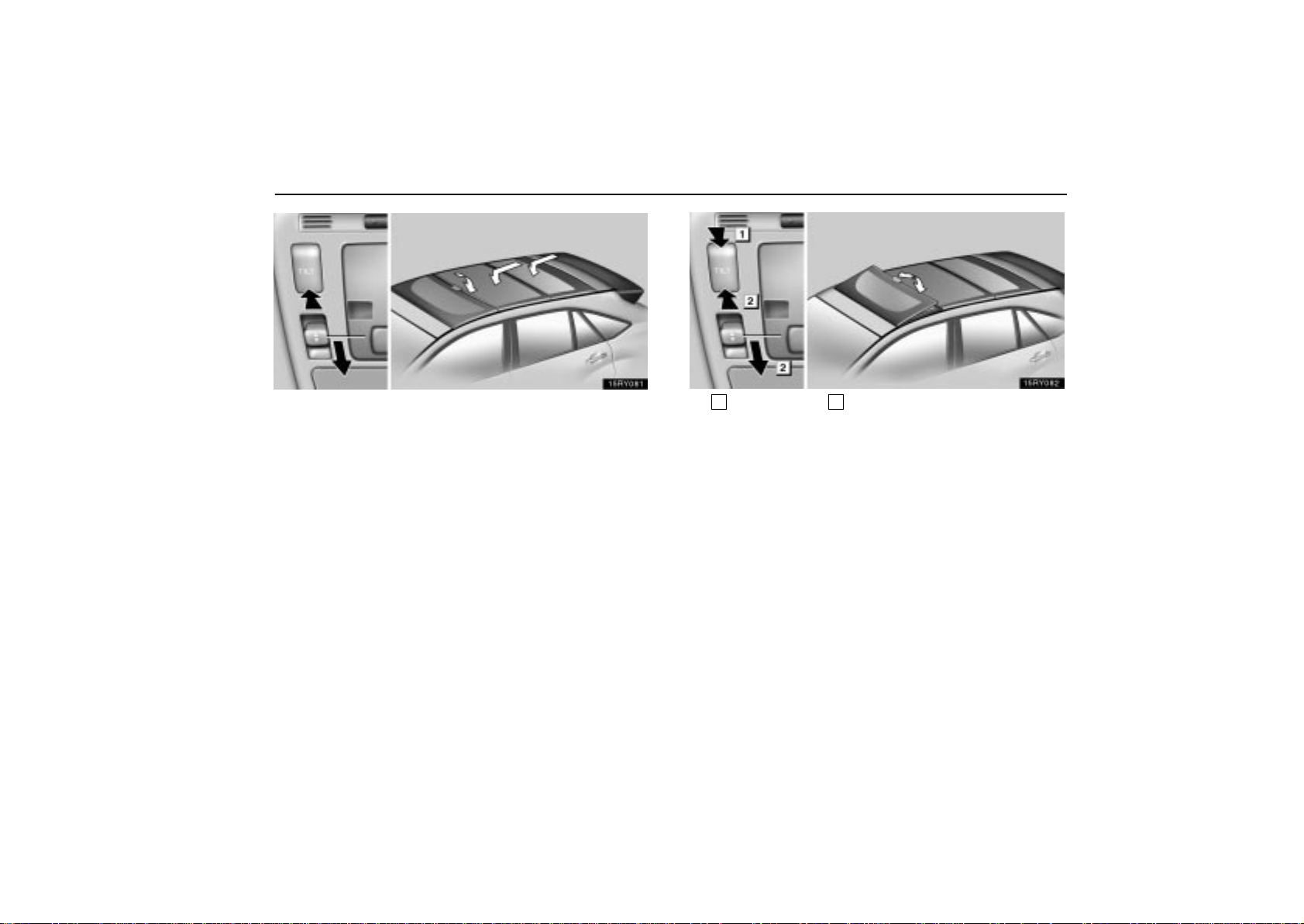
To close the moon roof, push the slide control switch
toward the front. The center and rear panels fully close.
Then push and hold the slide control switch toward the
front or the “TILT” switch on the front side until the front
panel is fully down. To stop partway, push either side of
the slide control switch or the “TILT” switch briefly.
The center and rear panels will not close automatically when
the center panel position is near its closed position. In this
case, push the slide control switch toward the front until the
panels fully close.
1
Tilt up
2
Tilt down
To tilt up the front panel, push the “TILT” switch on the rear
side. The moon roof will fully tilt up. T o stop partway, push
either side of the “TILT” switch or the slide control switch
briefly.
To tilt down the front panel, push and hold the “TILT”
switch on the front side or the slide control switch toward
the front until the panel is fully down.
149
Page 71

EXTERIOR EQUIPMENT
To operate the moon roof, the ignition key must be in the “ON”
position.
If the moon roof is left open when you turn the ignition key to
the “ACC” or “LOCK” position and open the driver’s door, a
buzzer will remind you to close the moon roof.
Retained accessory power operation: Even if the ignition
key is turned to the “ACC” or “LOCK” position, the moon roof
can be operated until either front door is opened (or for 43
seconds).
Jam protection function
If something gets caught between the moon roof and frame
during slide closing operation, the moon roof stops and
opens half way.
If something gets caught between the moon roof and frame
during tilting down operation, the moon roof stops and
opens fully.
If the moon roof receives a strong impact, this function may
work even if nothing is caught.
150
Page 72
EXTERIOR EQUIPMENT
If the battery is disconnected or run down
The moon roof may not operate automatically and the jam
protection function will not function correctly after you
reconnect, replace or recharge the battery. In any of these
cases, you should normalize the moon roof.
To normalize the moon roof, push the slide control switch
toward the front or the “TIL T” switch on the front side until the
front panel fully closes, and hold the switch for about 1 second.
Make sure that the moon roof opens and closes automatically.
If the moon roof cannot be operated properly, have it checked
by your Lexus dealer.
CAUTION
To avoid serious personal injury, you must do the
following.
While the vehicle is moving, always keep the heads,
hands and other parts of the bodies of all occupants
away from the roof opening. Otherwise, they could
be seriously injured if the vehicle stops suddenly or
if the vehicle is involved in an accident.
Before you close the moon roof, always make sure
there is nobody around the moon roof. You must also
make sure nobody places his or her head, hands and
other parts of the body in the roof opening. If
someone’s neck, head or hands get caught in the
closing roof, it could result in a serious injury. When
anyone closes the moon roof, first make sure it is safe
to do so.
Be sure to remove the ignition key when you leave
your vehicle.
Never leave anyone (particularly a small child) alone
in your vehicle, especially with the ignition key still
inserted. Otherwise, he/she could use the moon roof
switches and get trapped in the roof opening.
Unattended person ( p a rticularly a small child) can be
involved in a serious accident.
Never sit on top of the vehicle around the roof
opening.
Never try jamming any part of your body to activate
the jam protection function intentionally.
The jam protection function may not work if
something gets caught just before the moon roof is
fully closed.
151
Page 73
EXTERIOR EQUIPMENT
NOTICE
There is the possibility that water or rain will get into the
vehicle if you operate the moon roof after a rainfall,
snowfall or car wash. Wipe the moon roof dry with a
cloth before operating it.
152
Page 74
EXTERIOR EQUIPMENT
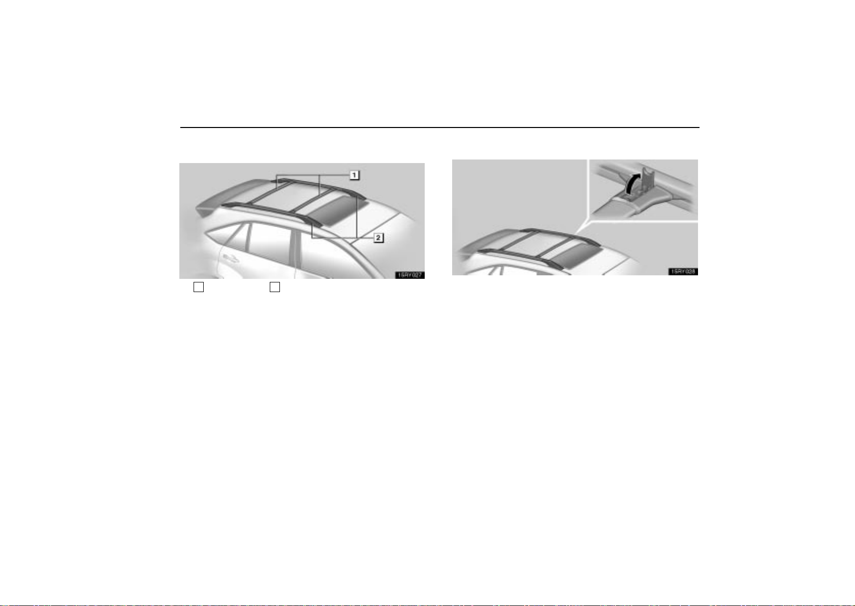
ROOF LUGGAGE CARRIER
1
Cross rails
The roof luggage carrier consists of roof rails and sliding
cross rails.
2
Roof rails
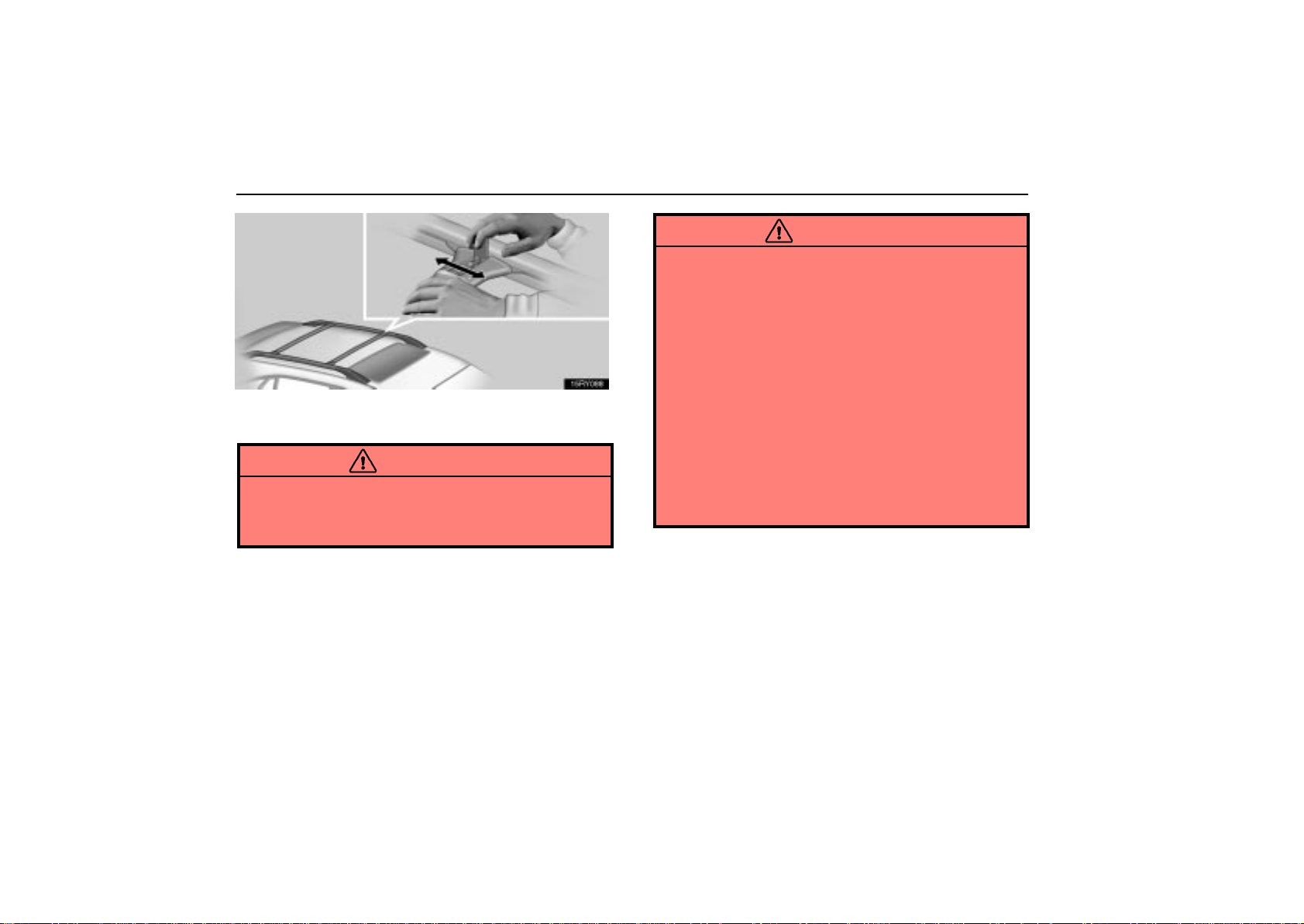
Adjusting the position of cross rails
1. Pull the lock release lever up to release the cross rails.
You can release the cross rails by operating only the single side
lock release lever.
153
Page 75
EXTERIOR EQUIPMENT
2. Slide the cross rails to the appropriate position for
loading luggage and release the lever.
CAUTION
Make sure the cross rails are locked securely by
pushing forward and rearward them. Failure to do so
may cause an unexpected accident or severe injury in
the event of emergency braking or a collision.
Follow the manufacturer’s instructions and precautions when
installing the attachments or their equivalent.
CAUTION
When you load cargo on the roof luggage carrier,
observe the following:
Place the cargo so that its weight is distributed
evenly between the front and rear axles.
If loading long or wide cargo, never exceed the
vehicle overall length or width. (See “Specifications”
on page 697 for information on your vehicle overall
length and width.)
Before driving, make sure the cargo is securely
fastened on the roof luggage carrier.
Loading cargo on the roof luggage carrier will make
the center of the vehicle gravity higher. Avoid high
speeds, sudden starts, sharp turns, sudden braking
or abrupt maneuvers, otherwise it may result in loss
of control or vehicle rollover due to failure to operate
this vehicle correctly.
154
Page 76
If driving for a long distance, on rough roads, or at
high speeds, stop the vehicle now and then during
the trip to make sure the cargo remains in its place.
Do not exceed 75 kg (165 lb.) cargo weight on the roof
luggage carrier.
NOTICE
When loading the luggages, be careful not to scratch
the surface of the moon roof.
EXTERIOR EQUIPMENT
155
Page 77

SECTION 1 –
INSTRUMENTS AND CONTROLS
Occupant restraint systems
Seats 157. . . . . . . . . . . . . . . . . . . . . . . . . . . . . . . . . . . . . . . . . . . . . . . . . . . . . . . . . . . . . . . . . . . . . . . . . . . . .
Front seats 157. . . . . . . . . . . . . . . . . . . . . . . . . . . . . . . . . . . . . . . . . . . . . . . . . . . . . . . . . . . . . . . . . . . . . . . .
Rear seats 165. . . . . . . . . . . . . . . . . . . . . . . . . . . . . . . . . . . . . . . . . . . . . . . . . . . . . . . . . . . . . . . . . . . . . . . .
Armrests 168. . . . . . . . . . . . . . . . . . . . . . . . . . . . . . . . . . . . . . . . . . . . . . . . . . . . . . . . . . . . . . . . . . . . . . . . . .
Head restraints 169. . . . . . . . . . . . . . . . . . . . . . . . . . . . . . . . . . . . . . . . . . . . . . . . . . . . . . . . . . . . . . . . . . . .
Seat belts 171. . . . . . . . . . . . . . . . . . . . . . . . . . . . . . . . . . . . . . . . . . . . . . . . . . . . . . . . . . . . . . . . . . . . . . . . .
SRS driver airbags and front passenger airbag 188. . . . . . . . . . . . . . . . . . . . . . . . . . . . . . . . . . . . . . . . .
SRS side airbags and curtain shield airbags 203. . . . . . . . . . . . . . . . . . . . . . . . . . . . . . . . . . . . . . . . . . .
Front passenger occupant classification system 220. . . . . . . . . . . . . . . . . . . . . . . . . . . . . . . . . . . . . . . .
Child restraint 225. . . . . . . . . . . . . . . . . . . . . . . . . . . . . . . . . . . . . . . . . . . . . . . . . . . . . . . . . . . . . . . . . . . . . .
Driving position memory system 252. . . . . . . . . . . . . . . . . . . . . . . . . . . . . . . . . . . . . . . . . . . . . . . . . . . . . .
6
156
Page 78
OCCUPANT RESTRAINT SYSTEMS
SEATS
While the vehicle is being driven, all vehicle occupants should
have the seatback upright, sit well back in the seat and properly
wear the seat belts provided.
CAUTION
Do not drive the vehicle unless the occupants are
properly seated. Do not allow any passengers to sit
in the luggage compartment or cargo area. Persons
not properly seated and/or not properly restrained by
seat belts can be severely injured in the event of
emergency braking or a collision.
During driving, do not allow any passengers to stand
up or move around between seats. Otherwise, severe
injuries can occur in the event of emergency braking
or a collision.
FRONT SEATS
Front seat precautions
Driver seat
CAUTION
The SRS driver airbag deploys with considerable force,
and can cause death or serious injury especially if the
driver is very close to the airbag. The National Highway
Traffic Safety Administration (“NHTSA”) advises:
Since the risk zone for driver airbag is the first 50 — 75
mm (2 — 3 in.) of inflation, placing yourself 250 mm (10
in.) from your driver airbag provides you with a clear
margin of safety. This distance is measured from the
center of the steering wheel to your breastbone. If you
sit less than 250 mm (10 in.) away now, you can change
your driving position in several ways:
Move your seat to the rear as far as you can while still
reaching the pedals comfortably.
157
Page 79
OCCUPANT RESTRAINT SYSTEMS
Slightly recline the back of the seat. Although vehicle
designs vary, many drivers can achieve the 250 mm
(10 in.) distance, even with the driver seat all the way
forward, simply by reclining the back of the seat
somewhat. If reclining the back of your seat makes
it hard to see the road, raise yourself by using a firm,
non–slippery cushion, or raise the seat if your vehicle
has that feature.
If your steering wheel is adjustable, tilt it downward.
This points the airbag toward your chest instead of
your head and neck.
The seat should be adjusted as recommended by
NHTSA above, while still maintaining control of the foot
pedals, steering wheel, and your view of the instrument
panel controls.
Front passenger seat
CAUTION
The SRS front passenger airbag also deploys with
considerable force, and can cause death or serious
injury especially if the front passenger is very close to
the airbag. The front passenger seat should be as far
from the airbag as possible with the seatback adjusted,
so the front passenger sits upright.
158
Page 80
OCCUPANT RESTRAINT SYSTEMS
Front seats (with SRS side airbags)
CAUTION
The SRS side airbags are installed in the driver and front
passenger seats. Observe the following precautions.
Do not lean against the front door when the vehicle
is in use, since the side airbag inflates with
considerable speed and force. Otherwise, you may
be killed or seriously injured.
Do not use seat accessories which cover the area
where the s i d e airbags inflate. Such accessories may
prevent the side airbags from activating correctly,
causing death or serious injury.
Do not modify or replace the seats or upholstery of
the seats equipped with side airbags. Such change
may prevent the side airbag system from activating
correctly, disable the system or cause the side
airbags to inflate accidentally, resulting in death or
serious injury.
NOTICE
Do not operate the control switch in more than one
dimension at a time. It may cause electrical overload.
Seat adjustment precautions
CAUTION
Do not adjust the seat while the vehicle is moving as
the seat may unexpectedly move and cause the
driver to lose control of the vehicle.
Be careful that the seat does not hit a passenger,
luggage or the rear seat.
159
Page 81
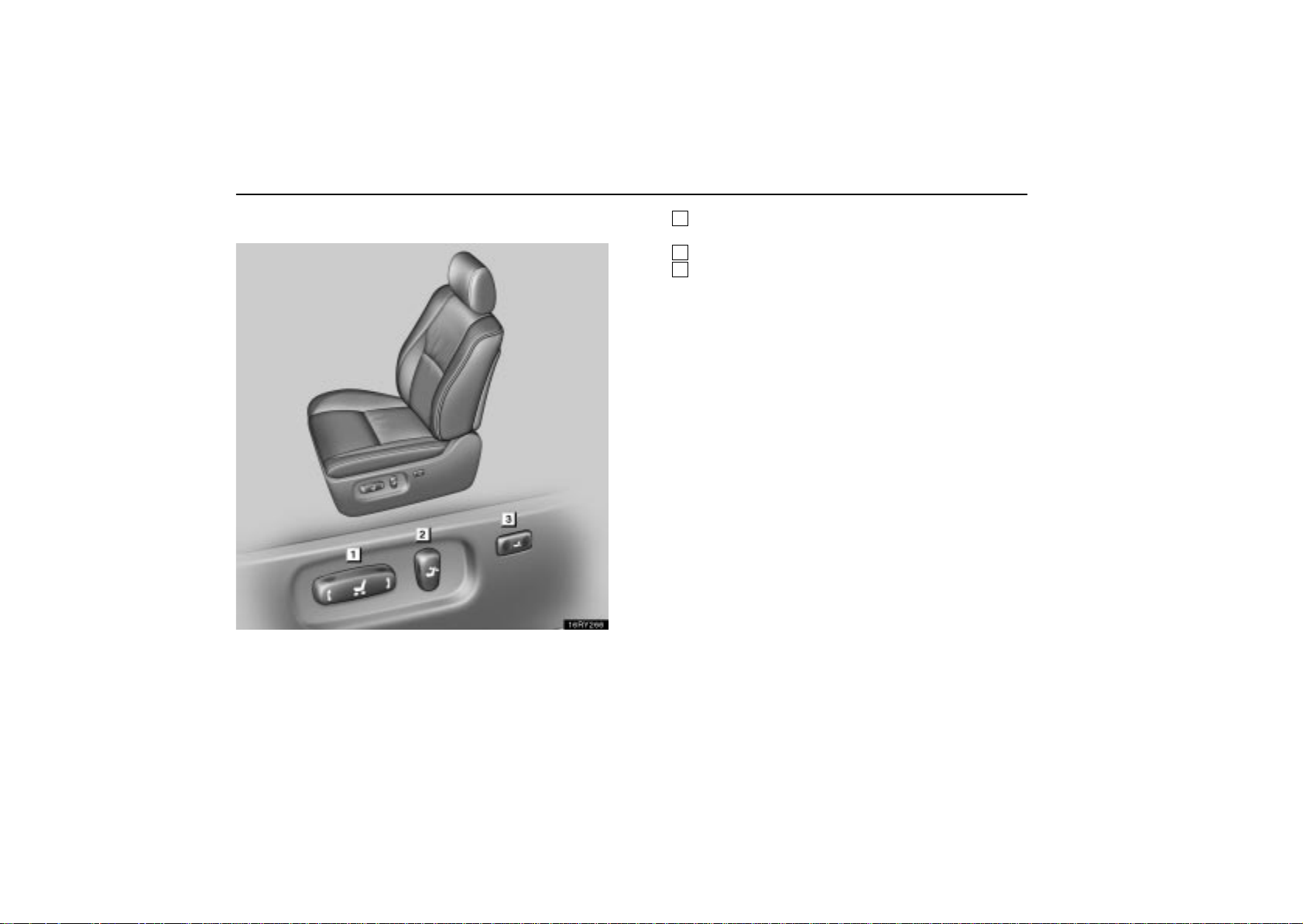
OCCUPANT RESTRAINT SYSTEMS
Adjusting front seats
1
Seat position control, seat cushion angle and
height control switch
2
Seatback angle control switch
3
Lumbar support control switch
160
Page 82
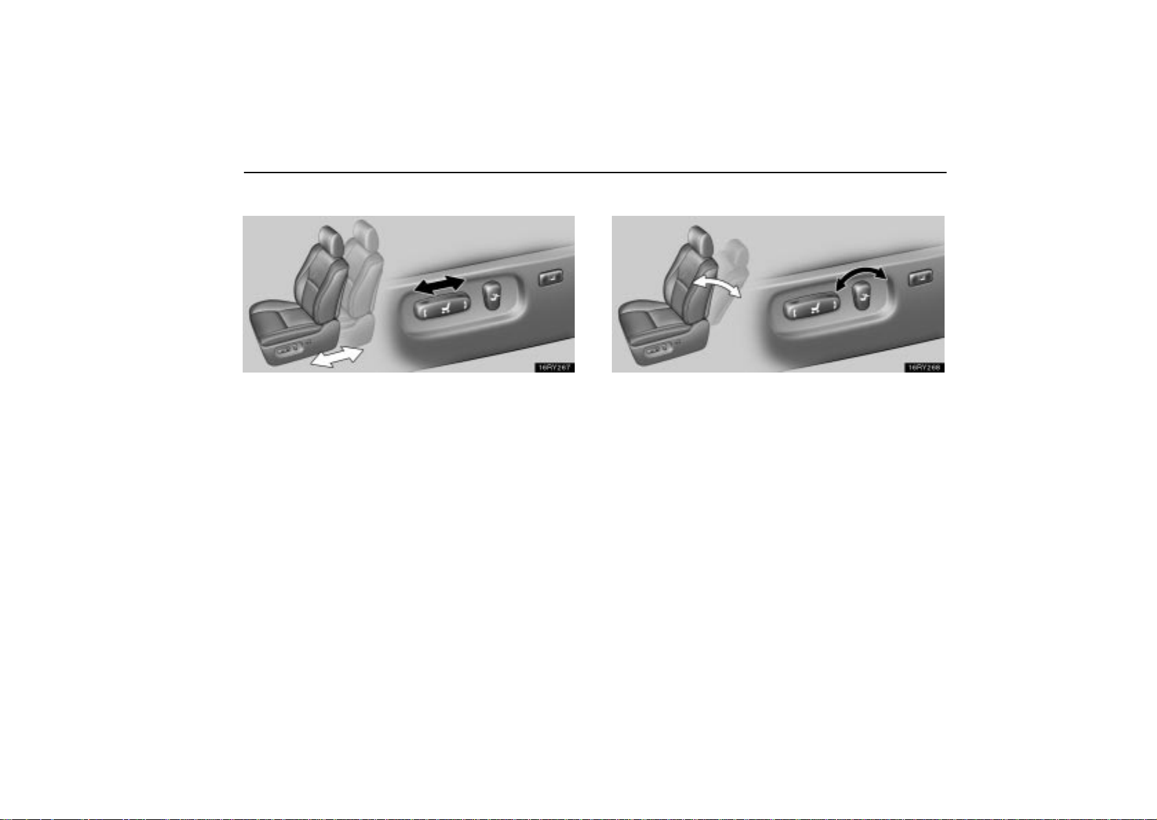
OCCUPANT RESTRAINT SYSTEMS
Adjusting seat position
Move the control switch in the desired direction.
Releasing the switch will stop the seat in that position. Do not
place anything under the seat, as this might interfere with the
seat movement.
Adjusting seatback angle
Move the control switch in the desired direction.
Releasing the switch will stop the seatback in that position.
161
Page 83
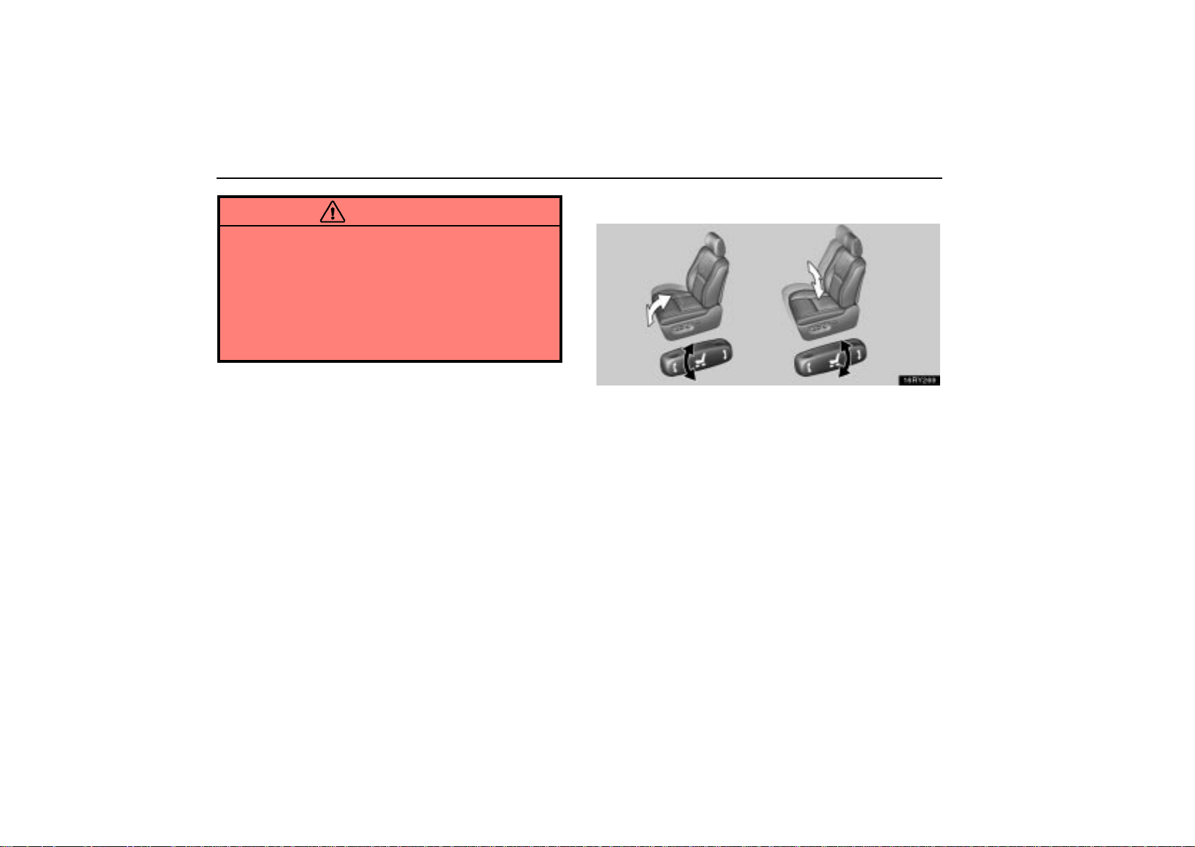
OCCUPANT RESTRAINT SYSTEMS
CAUTION
Avoid reclining the seatback any more than needed.
The seat belts provide maximum protection in a frontal
or rear collision when the driver and the front passenger
are sitting up straight and well back in the seats. If you
are reclined, the lap belt may slide past your hips and
apply restraint forces directly to the abdomen or your
neck may contact the shoulder belt. In the event of a
frontal collision, the more the seat is reclined, the
greater the risk of death or personal injury.
Adjusting seat cushion angle and height
Move the control switch in the desired direction.
Releasing the switch will stop the seat cushion in that position.
162
Page 84
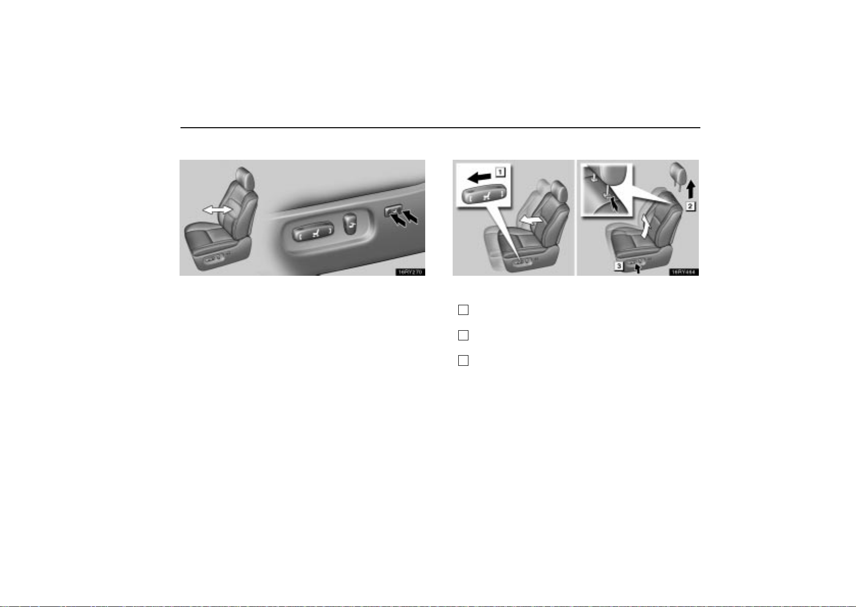
OCCUPANT RESTRAINT SYSTEMS
Adjusting lumbar support (driver’s seat only)
Push the control switch on either side.
The amount of lumbar support will change while the switch is
pushed.
Flattening seatbacks
Before flattening seatbacks, slide the rear seats as far
back as possible.
1
Push the seat position control switch forward to move the
seat forward.
2
Push the lock release button on the head restraint to
remove it.
3
Push the seat position control switch upward to raise the
seat (driver’s seat only).
163
Page 85
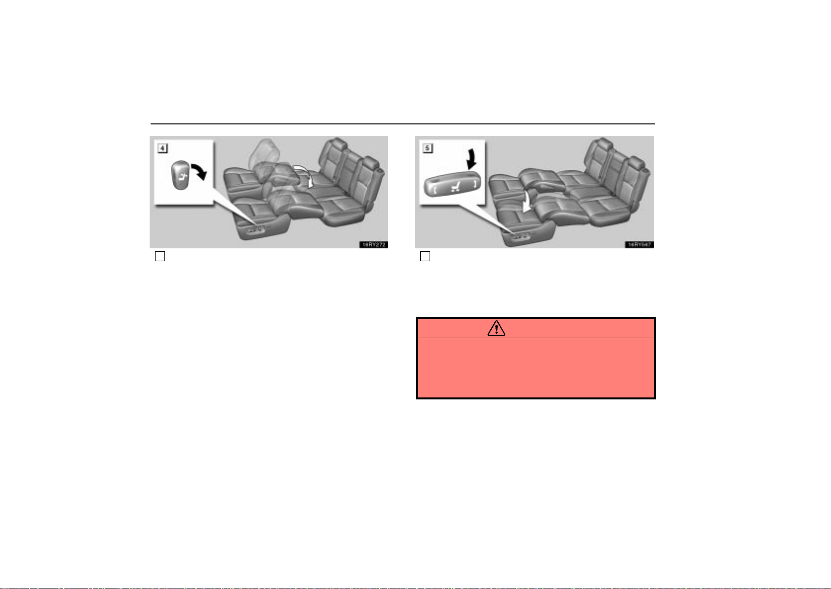
OCCUPANT RESTRAINT SYSTEMS
164
4
Move the seatback angle control switch backward to
flatten the seatback.
5
Push the seat position control switch downward to lower
the seat at the same level as the rear seat (driver’s seat
only).
After returning the seat to its original position, be certain to
replace the head restraint.
CAUTION
Do not allow passengers to ride on the flattened seat
while driving; use the seat in the normal position.
After putting back the seat, try pushing the seatback
forward and rearward to make sure it is secured in
place. Be certain to replace the head restraint.
Page 86
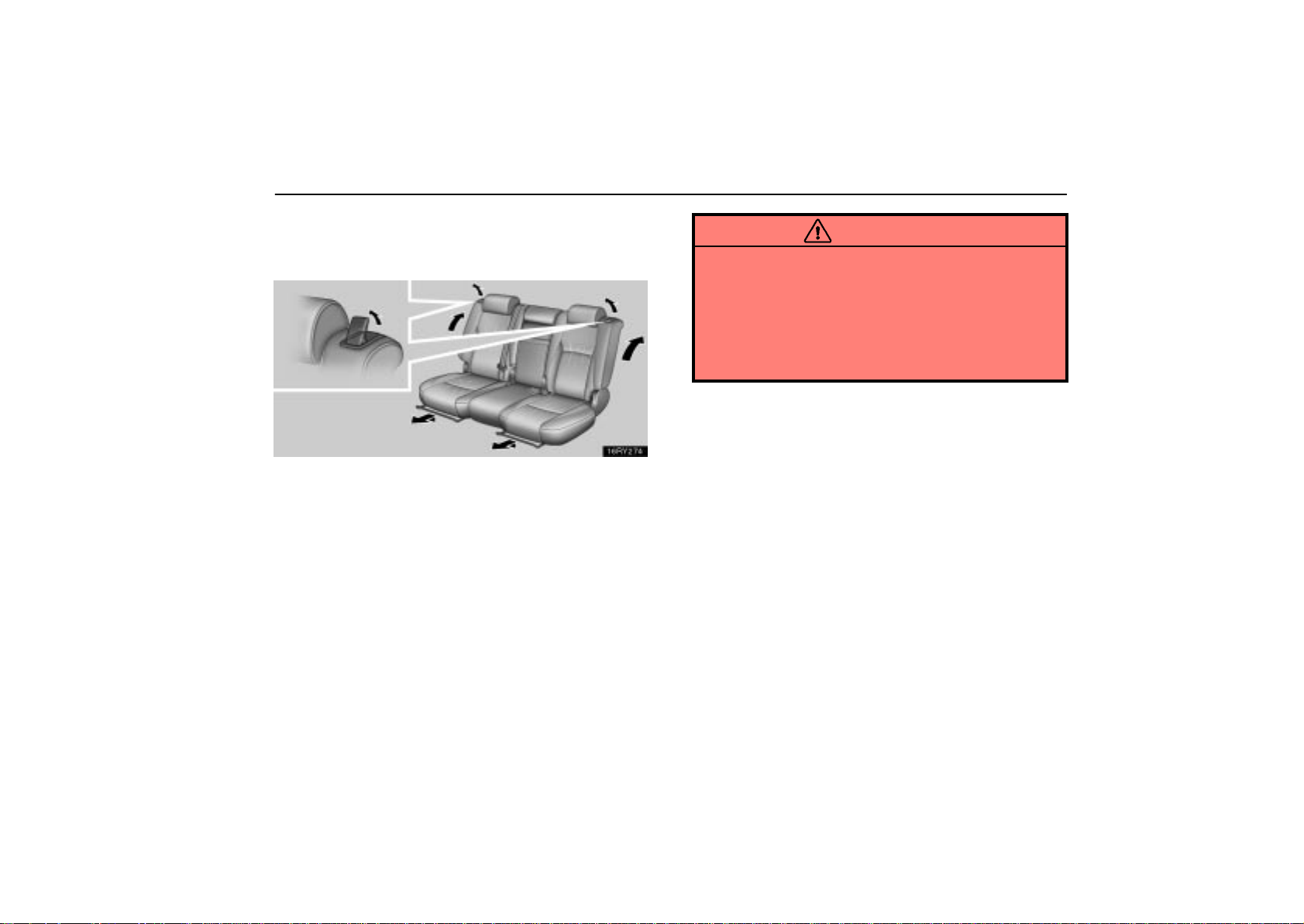
OCCUPANT RESTRAINT SYSTEMS
REAR SEATS
Sliding and reclining rear seats
Sliding the rear seats — Hold the center of the slide lock
release lever and pull it up. Then slide the seat to the
desired position with slight body pressure and release the
lever.
Reclining the rear seats — Pull the seatback lock release
lever. Then lean back to the desired angle and release the
lever.
CAUTION
Avoid reclining the seatback any more than needed.
The seat belts provide maximum protection when the
passengers are sitting up straight and well back in the
seats. If you are reclined, the lap belt may slide past
your hips and apply restraint forces directly to the
abdomen or your neck may contact the shoulder belt.
In the event of a frontal collision, the more the seat is
reclined, the gr e a t e r t h e r i s k o f death or personal injury.
165
Page 87
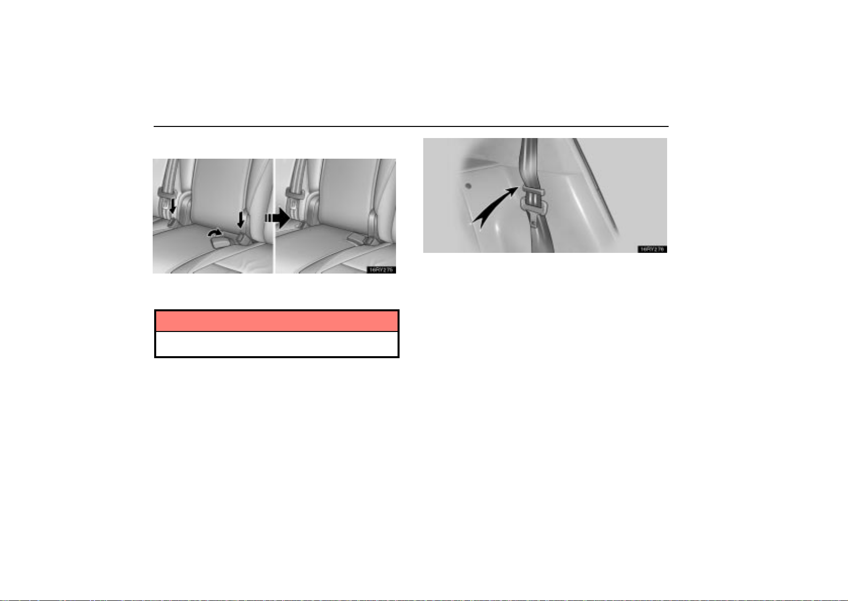
OCCUPANT RESTRAINT SYSTEMS
Folding down rear seatbacks
Before folding down rear seatbacks
Stow the rear seat belt buckles as shown above.
NOTICE
The seat belts and the buckles must be stowed before
you fold down the rear seatbacks.
Seat belt hanger
For the outer seat belts, use the seat belt hangers to
prevent the belts from being tangled.
166
Page 88
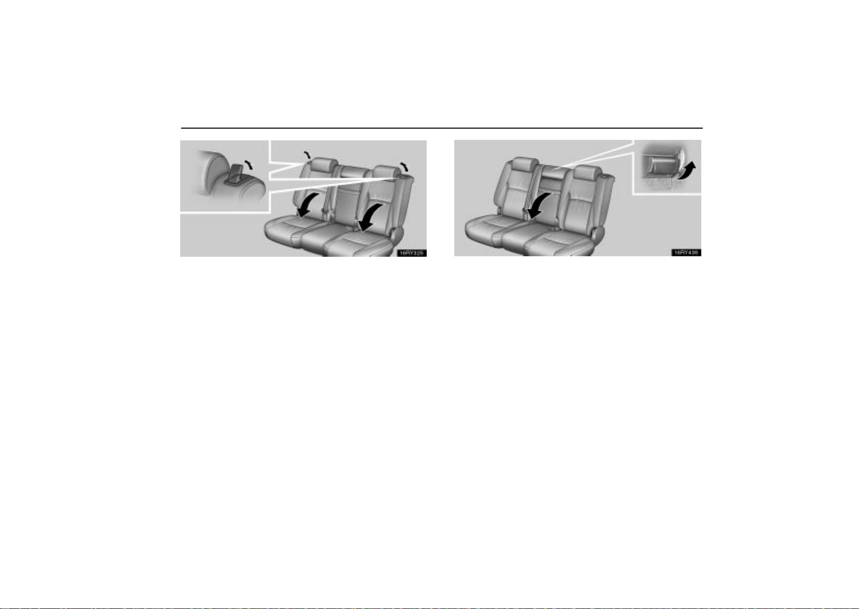
Folding down rear seatbacks
Lower the head restraints, unlock the seatbacks by pulling
the seatback lock release lever and fold them down until
they lock.
When returning the rear seatbacks to their original
positions, unlock the seatbacks by pulling the seatback
lock release lever and lift them up until they lock.
OCCUPANT RESTRAINT SYSTEMS
Folding down rear center seatback
Y ou can fold down only the rear center seatback.
To fold down the center seatback, lower the center head
restraint, unlock the seatback by pulling the center
seatback lock release lever behind the seatback and fold
it down. To return the center seatback to its original
position, lift the center seatback up until it locks.
167
Page 89
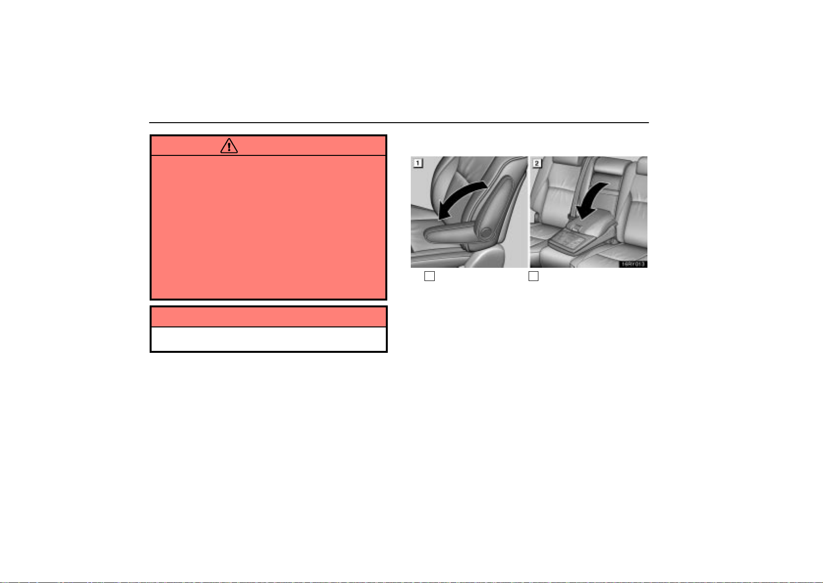
OCCUPANT RESTRAINT SYSTEMS
CAUTION
When folding down the rear seatback, be careful not
to get hands or feet pinched between the rear console
box and the rear seat.
When returning the seatback to the upright position,
observe the following precautions in order to prevent
personal injury in a collision or sudden stop:
Make sure the seat is securely locked by pushing
forward and rearward on the top of the seatback.
Failure to do so will prevent the seat belt from
operating properly.
Make sure the seat belts are not twisted or caught
under the seat and are arranged in their proper
position and are ready to use.
NOTICE
To prevent damage to the armrests, avoid putting heavy
loads on them.
ARMRESTS
1
Front
To use the armrests, pull them down as shown above.
2
Rear
168
Page 90
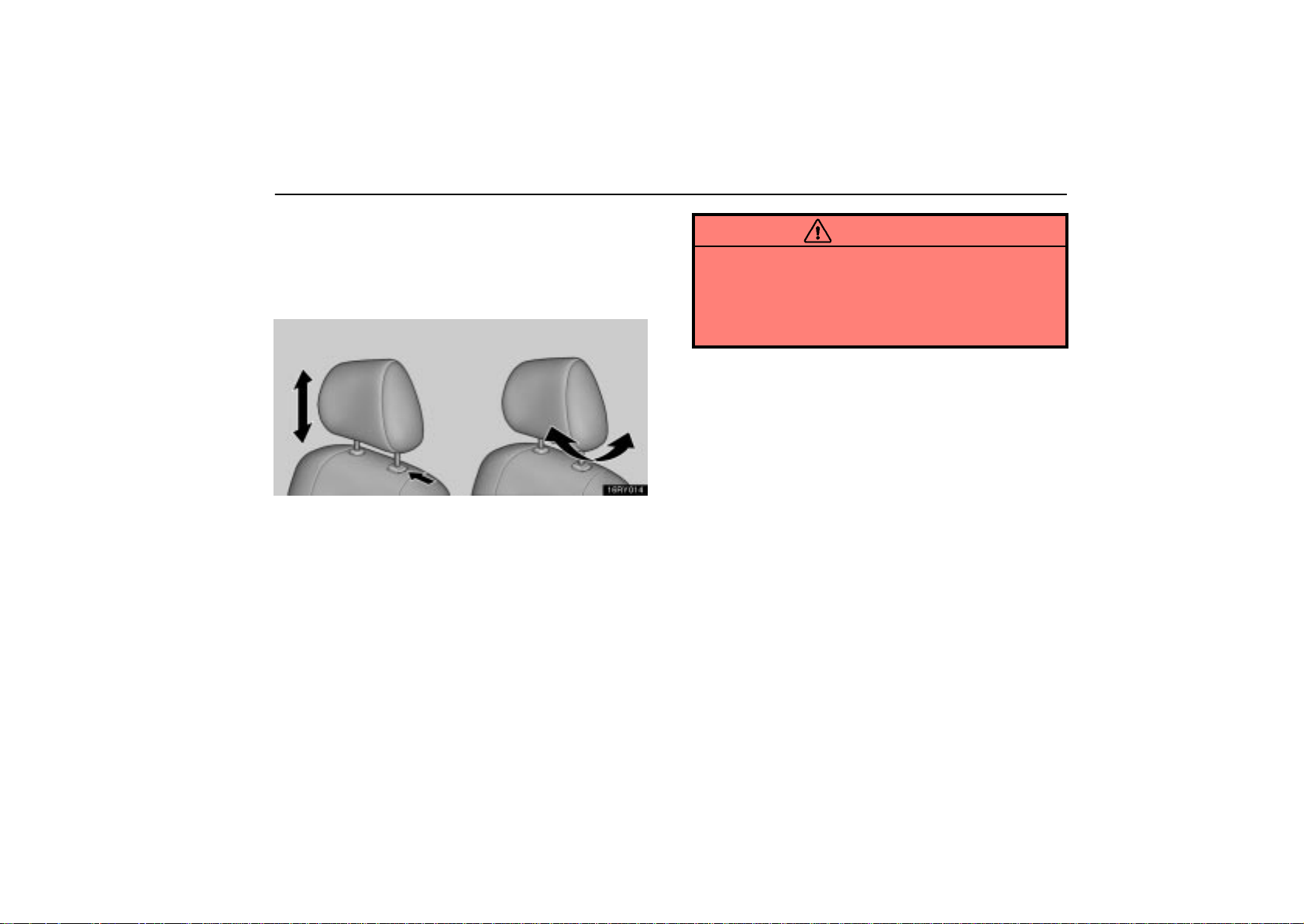
OCCUPANT RESTRAINT SYSTEMS
HEAD RESTRAINTS
For your safety and comfort, adjust the head restraint
before driving.
Front seats
To raise the head restraint, pull it up. To lower it, press the
lock release button and push the head restraint down. T o
move the head restraint forward or rearward, pull or push
the base of the head restraint.
The head restraint is most effective when it is close to your
head. Therefore, using a cushion on the seatback is not
recommended.
CAUTION
Adjust the center of the head restraint so that it is
closest to the top of your ears.
After adjusting the head restraint, make sure it is
locked in position.
Do not drive with the head restraints removed.
169
Page 91
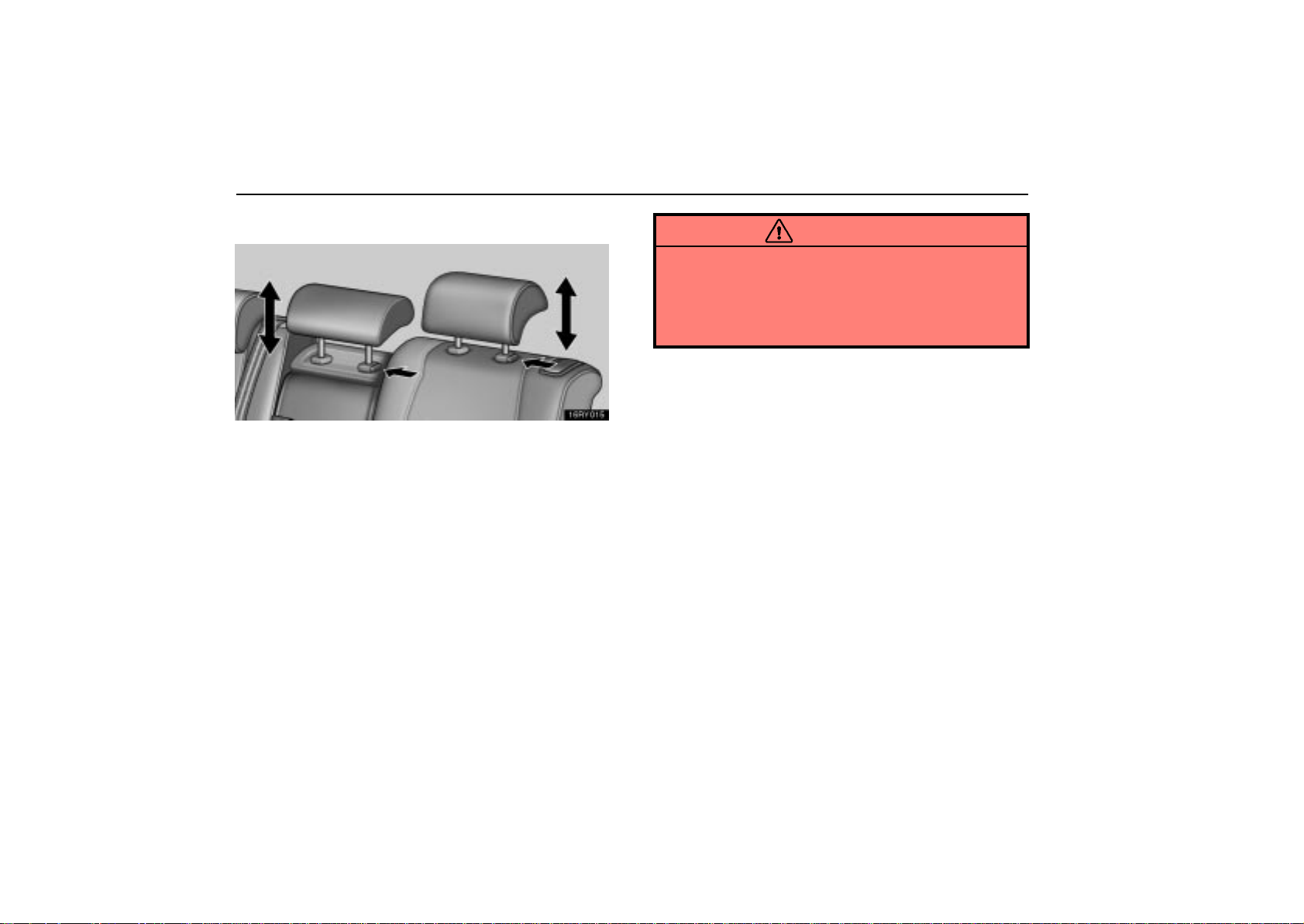
OCCUPANT RESTRAINT SYSTEMS
Rear seats
To raise the head restraint, pull it up. To lower it, press the
lock release button and push the head restraint down.
Rear center head restraint — When an occupant sits on the
rear center seat, always pull up the rear center head restraint
to the lock position.
The head restraint is most effective when it is close to your
head. Therefore, using a cushion on the seatback is not
recommended.
CAUTION
Adjust the center of the head restraint so that it is
closest to the top of your ears.
After adjusting the head restraint, make sure it is
locked in position.
Do not drive with the head restraints removed.
170
Page 92

OCCUPANT RESTRAINT SYSTEMS
SEAT BELTS
Seat belt precautions
Lexus strongly urges that the driver and passengers in the
vehicle be properly restrained at all times with the seat belts
provided. Failure to do so could increase the chance of injury
and/or the severity of injury in accidents.
The seat belts provided for your vehicle are designed for
people of adult size, large enough to properly wear them.
Child. Use a child restraint system appropriate for the child
until the child becomes large enough to properly wear the
vehicle’s seat belts. See “Child restraint” on page 225 for
details.
If a child is too large for a child restraint system, the child should
sit in the rear seat and must be restrained using the vehicle’s
seat belt. According to accident statistics, the child is safer
when properly restrained in the rear seat than in the front seat.
If a child must sit in the front seat, the seat belts should be worn
properly . I f a n accident occurs and the seat belts are not worn
properly, the force of the rapid inflation of the airbag may cause
death or serious injury to the child.
Do not allow any children to stand up or kneel on either rear or
front seats. An unrestrained child could suffer serious injury or
death during emergency braking or a collision. Also, do not let
the child sit on your lap. Holding a child in your arms does not
provide sufficient restraint.
Pregnant woman. Lexus recommends the use of a seat belt.
Ask your doctor for specific recommendations. The lap belt
should be worn securely and as low as possible over the hips
and not on the waist.
Injured person. Lexus recommends the use of a seat belt.
Depending on the injury, first check with your doctor for specific
recommendations.
171
Page 93
OCCUPANT RESTRAINT SYSTEMS
CAUTION
Persons should ride in their seats properly wearing
their seat belts whenever the vehicle is moving.
Otherwise, they are much more likely to suffer serious
bodily injury or death in the event of sudden braking or
a collision.
When using the seat belts, observe the following:
Use the belt for only one person at a time. Do not use
a single belt for two or more people — even children.
Avoid reclining the seatback any more than needed.
The seat belts provide maximum protection in a
frontal or rear collision when the driver and the front
passenger are sitting up straight and well back in the
seats. If you are reclined, the lap belt may slide past
your hips and apply restraint forces directly to the
abdomen or your neck may contact the shoulder belt.
In the event of a frontal collision, the more the seat is
reclined, the greater the risk of death or personal
injury.
Be careful not to damage the belt webbing or
hardware. Take care that they do not get caught or
pinched in the seat or doors.
Inspect the belt system periodically . Check for cuts,
fraying, and loose parts. Damaged parts should be
replaced. Do not disassemble or modify the system.
172
Page 94
Keep the belts clean and dry. If they need cleaning,
use a mild soap solution or lukewarm water. Never
use bleach, dye, or abrasive cleaners, or allow them
to come into contact with the belt — they may
severely weaken the belts. (See “Cleaning the
interior” on page 704 for instructions.)
Replace the belt assembly (including bolts) if it has
been used in a severe impact. The entire assembly
should be replaced even if damage is not obvious.
OCCUPANT RESTRAINT SYSTEMS
173
Page 95
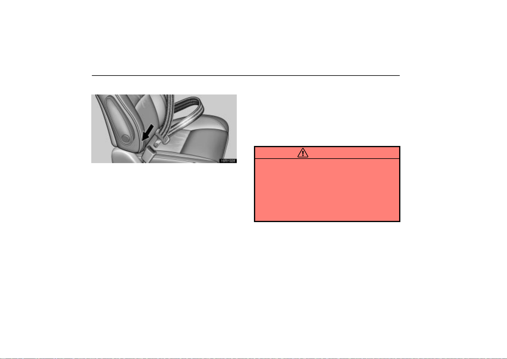
OCCUPANT RESTRAINT SYSTEMS
Fastening front and rear seat belts
Adjust the seat as needed and sit up straight and well back
in the seat. T o fasten your belt, pull it out of the retractor
and insert the tab into the buckle.
You will hear a click when the tab locks into the buckle.
The seat belt length automatically adjusts to your size and the
seat position.
The retractor will lock the belt during a sudden stop or on
impact. It also may lock if you lean forward too quickly. A slow ,
easy motion will allow the belt to extend, and you can move
around freely.
When a rear seat belt is completely extended and is then
retracted even slightly, the belt is locked in that position and
cannot be extended. This feature is used to hold the child
restraint system securely . (For details, see “Child restraint” on
page 225.) To free the belt again, fully retract the belt and then
pull the belt out once more.
If the seat belt cannot be pulled out of the retractor, firmly pull
the belt and release it. You will then be able to smoothly pull
the belt out of the retractor.
CAUTION
After inserting the tab, make sure the tab and buckle
are locked and that the belt is not twisted.
Do not insert coins, clips, etc. in the buckle as this
may prevent you from properly latching the tab and
buckle.
If the seat belt does not function normally,
immediately contact your Lexus dealer. Do not use
the seat until the seat belt is fixed, because it cannot
protect an adult occupant or your child from injury.
174
Page 96
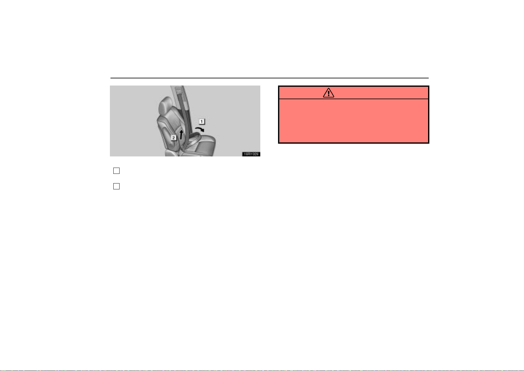
Adjust the position of the lap and shoulder belts.
1
Position the lap belt as low as possible on your hips — not
on your waist.
2
Adjust it to a snug fit by pulling the shoulder portion
upward through the latch plate.
OCCUPANT RESTRAINT SYSTEMS
CAUTION
Both high–positioned lap belts and loose–fitting
belts could cause serious injuries due to sliding
under the lap belt during a collision or other
unintended event. Keep the lap belt positioned as
low on hips as possible.
Do not place the shoulder belt under your arm.
175
Page 97
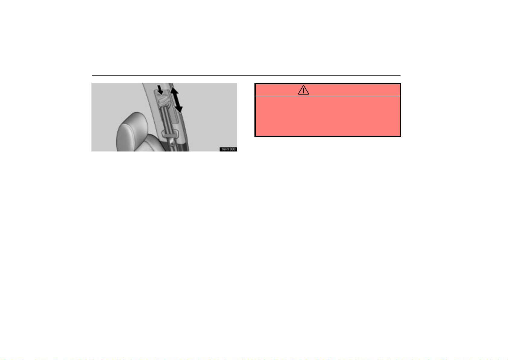
OCCUPANT RESTRAINT SYSTEMS
Front seat belts only
Adjust the shoulder anchor position to your size.
To raise the anchor position, push the anchor up. To lower the
anchor position, support the anchor while you push the lock
release button then slide the anchor down. After the
adjustment, make sure the anchor is locked in position.
CAUTION
Always make sure the shoulder belt is positioned
across the center of your shoulder. The belt should be
kept away from your neck, but not falling off your
shoulder. Failure to do so could reduce the amount of
protection in an accident and cause serious injuries in
a collision.
176
Page 98
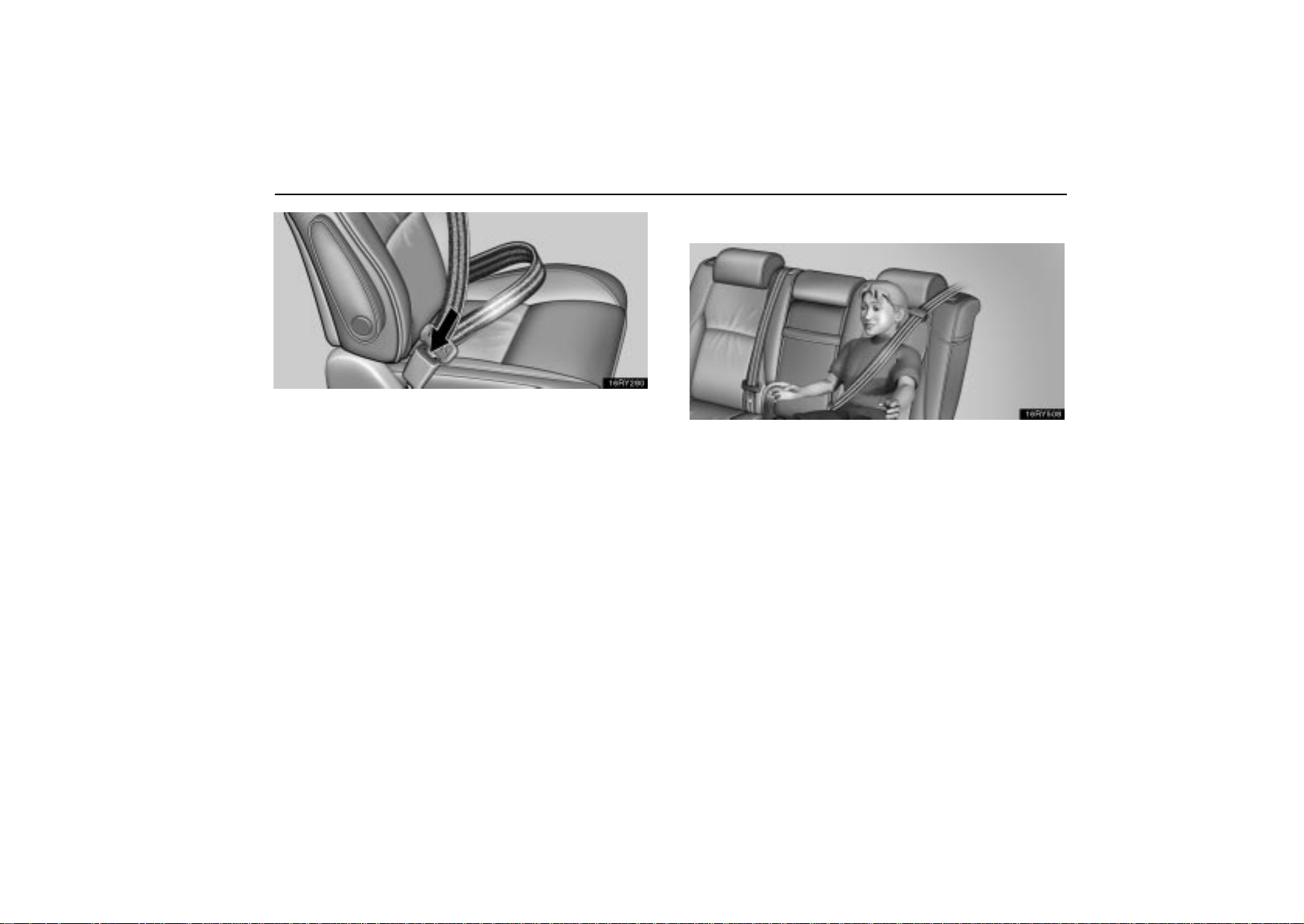
To release the belt, press the buckle release button and
allow the belt to retract.
If the belt does not retract smoothly, pull it out and check for
kinks or twists. Then make sure it remains untwisted as it
retracts.
OCCUPANT RESTRAINT SYSTEMS
Seat belt comfort guides
The outboard shoulder belt comfort guides for the rear
seat outboard positions will provide added seat belt
comfort for children who have outgrown child restraints
and for small adults. When the outboard shoulder belt is
inserted through the guide, the comfort guide pulls the
belt away from the neck and head of an occupant.
To use the comfort guide, do as follows.
177
Page 99
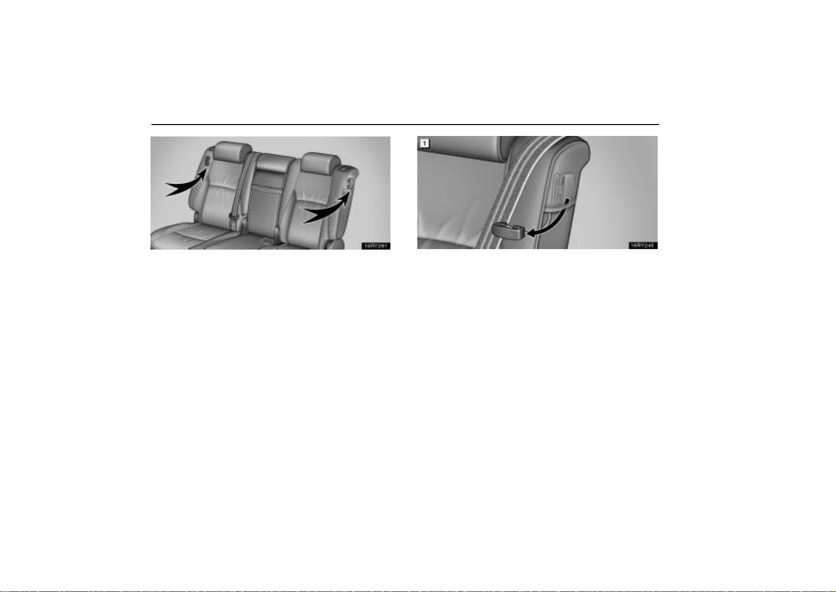
OCCUPANT RESTRAINT SYSTEMS
Seat belt comfort guides are stored in the both pockets on the
sides of the rear seatback.
178
INSTALLING THE COMFORT GUIDE
1. Pull the comfort guide from the pocket.
Page 100
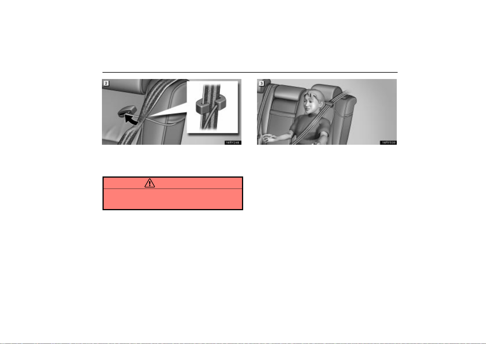
OCCUPANT RESTRAINT SYSTEMS
2. Pinch the two edges of the shoulder belt for the rear
seat outboard position with your fingers and slide the belt
past the slot of the guide as shown above. At this time, the
elastic cord must be behind the seat belt.
CAUTION
Make sure the belt is not twisted and that it lies flat. The
elastic cord must be behind the belt and the guide must
be on the front.
3. Buckle, position and release the seat belt. (For wearing
the seat belt, see page 174.) Make sure the shoulder belt
crosses the shoulder.
179
 Loading...