


KM-3060
Table of contents
 Loading...
Kyocera KM-3060, FS-9520DN, FS-2000D, KM-C2520, KM-5230 Manual
...
PRESCRIBE Commands
Technical Reference


Notice
General Infomation
We shall have no liability or responsibility to customers or any other person or entity with respect to any liability, loss or
damage caused or alleged to be caused directly or indirectly by equipment sold or furnishe d by us, inc luding, but not limited
to, any interruption of service, loss of business or anticipatory profits, or consequential damages resulting from the use or
operation of the equipment or software.
NO LIABILITY WILL BE ASSUMED FOR ANY DAMAGE CAUSED BY IMPROPER INSTALLATION.
Notice on Software
SOFTWARE USED WITH THIS PRINTING SYSTEM MUST SUPPORT IT’S NATIVE MODE (PR ESCRIBE) OR ONE OF
ITS EMULATION MODES.
This manual, the computer programs in the printing system referred to in this manual, and any other copyrightable subject
matter sold or provided with or in connection with the sale of the printing system, are protected by copyright. All rights are
reserved. Copying or other reproduction of all or part of this manual, the computer programs, or any other copyrightable
subject matter without the prior written consent of Kyocera Mita Corporation is prohibited. Any cop ies made of all or part of
this manual, the computer programs, or any other copyrightable subject must contain the same copyright notice as the
material from which the copying is done.
The information in this manual is subject to ch ange wit hout no tificat ion. Addit ional pages may be inserted in f uture ed itions.
The user is asked to excuse any omissions or errors in the present edition.
No responsibility is assumed if accidents occur while the user is following the instructions in this manual. No responsibility
is assumed for defects in the printing system’s firmware.
Regarding Tradenames
PRESCRIBE is a registered trademark of Kyocera Corporation. KPDL is a trademark of Kyocera Corporation.
Diablo 630 is a product of Xerox Corpo ra tion. IBM Proprinter X-2 4E is a product of Internat ional B usines s Machines C orp o-
ration. Epson LQ-850 is a product of Seiko Epson Corporation. HP LaserJet, Hewlett-Packard, PCL, and HP-GL/2 are registered trademarks of Hewlett-Packard Company. Other product names and company names that appear in this manual
are trademarks or registered trademarks of their respective owners.
The Kyocera printing systems use PeerlessPrint5 to provide the HP LaserJet compatible PCL5 language emulation.
PeerlessPrint5 is a trademark of The Peerless Group, Redondo Beach, CA 90278, U.S.A.
© Copyright 2005 - 2008 KYOCERA MITA Corporation
All rights reserved
Revision 4.51 2008.6
Typeface Trademark Acknowledgement
All resident fonts in the printing system are licensed from Bitstream Inc. and Agfa corporation. For font license information
for each model, refer to the User’s Manual.
Helvetica, Palatino and Times are registered trademarks of Linotype-Hell AG. Century Sch oolbook, Stymie, and CooperBlack are trademarks of Kingsley-ATF Type Corporation. ITC Avant Garde Gothic, ITC ZapfChancery, ITC ZapfDingbats,
ITC Souvenir, ITC Benguiat, and ITC Bookman are registered trademarks of International Typeface Corporation. Revue is
a trademark of Esselte Pendaflex Corporation in the U.S., Letraset Canada Ltd. in Canada, and Esselte Letraset Ltd. elsewhere.
Agfa Japan License Agreement Guidelines for the Resident Fonts
1. Software shall mean the digitally encoded, machine readable, scalable outline data as encoded in a s pecial forma t as
well as the UFST Software.
2. You agree to accept a no n-exclusive license to us e the Software to re produce and display weight s, styles and versions
of letters, numerals, characters and symbols (“Typefaces”) solely for your own customary business or personal purposes at the address stated on the registration card you return to Agfa Japan. Under the terms of this License Agreement, you have the right to use the Fonts on up to three printing systems. If you need to have access to the fonts on
i

more than three printing systems, you need to acquire a multi-user license agreement which can be obtained from
Agfa Japan. Agfa Japan retains all rights, titl e and int erest t o the Sof tware and Typefaces and no rights are grant ed to
you other than a License to use the Software on the terms expressly set forth in this Agree m ent.
3. To protect proprietary rights of Agfa Japan, you agree to maintain the Software and other proprietary information concerning the Typeface s in strict confide nce and to establish re asonable proced ures regulat ing access to and use of the
Software and Typefaces.
4. You agree not to d uplicate or copy the Sof tware or Typefaces, except that you ma y make on e backup co py. You agree
that any such copy shall contain the same proprietary notices as those appearing on the original.
5. This License shall continue until the last use of the Software and Typefaces, unless sooner terminated. This License
may be terminated by Agfa Japan if you fail to comply with the terms of this License and such failure is not remedied
within thirty (30) days after notice from Agfa Japan. When this Licen se expire s or is termina te d, you s hall either ret urn
to Agfa Japan or destroy all copies of the Software and Typefaces and documentation as requested.
6. You agree that you will not modify, alter, disassemble, decrypt, reverse engineer or decompile the Software.
7. Agfa Japan warrants that for ninety (90) days after delivery, the Software will perform in accord ance with Agfa Japanpublished specifications, and the diskette will be free from defects in material and workmanship. Agfa Japan does not
warrant that the Software is free from all bugs, errors and omissions.
THE PARTIES AGREE THAT ALL OTHER WARRANTIES, EXPRESSED OR IMPLIED, INCLUDING WARRANTIES
OF FITNESS FOR A PARTICULAR PURPOSE AND MERCHANTABILITY, ARE EXCLUDED.
8. Your ex clusive remedy and the sole liability of Agfa Japan in connection with the Software and Typefaces is repair or
replacement of defective parts, upon their return to Agfa Japan.
IN NO EVENT WILL AGFA JAPAN BE LIABLE FOR LOST PROFITS, LOST DATA, OR ANY OTHER INCIDENTAL
OR CONSEQUENTIAL DAMAGES, OR ANY DAMAGES CAUSED BY ABUSE OR MISAPPLICATION OF THE
SOFTWARE AND TYPEFACES.
9. New York, U.S.A. law governs this Agreement.
10. You shall not sublicense, sell, le ase, or othe rwise tr ansfer the Software and/ or Typefaces without the prior written consent of Agfa Japan.
11. Use, duplication or disclosure by the Government is subject t o restrictions as set forth in the Rights in Technical Data
and Computer Software clause at FAR 252-227-7013, subdivision (b)(3)(ii) or subparagraph (c)(1)(ii), as appropriate.
Further use, duplication or disclosure is subject to restrictions applicable to restricted rights software as set forth in
FAR 52.227-19 (c)(2).
12. YOU ACKNOWLEDGE THAT YOU HAVE READ THIS AGREEMENT, UNDERSTAND IT, AND AGREE TO BE
BOUND BY ITS TERMS AND CONDITIONS. NEITHER PARTY SHALL BE BOUND BY ANY STATEMENT OR REPRESENTATION NOT CONTAINED IN THIS AGREEMENT. NO CHANGE IN THIS AGREEMENT IS EFFECTIVE
UNLESS WRITTEN AND SIGNED BY PROPERLY AUTHORIZED REPRESENTATIVES OF EACH PARTY. BY
OPENING THIS DISKETTE PACKAGE, YOU AGREE T O ACCEPT THE TERMS AND CONDITIONS OF THIS
AGREEMENT.
ii

Introduction
This manual contains information needed to use the firmware features provided by the
Kyocera printing system. Among these features is PRESCRIBE, a highly accessible,
human-readable command language that makes it easy for programmers to take full
advantage of the printing system’s capability.
The PRESCRIBE command language allows to:
• extensive manipulation of fonts and character code tables
• use the ability to draw objects by constructing and manipulating paths including
ellipses and round boxes, etc.
• execute macros including carbon-copy macro
• control external optional units (feeders, etc.)
You can access the features of PRESCRIBE from any of the seven emulation modes.
These modes include:
• Hewlett-Packard LaserJet emulation
• Hewlett-Packard HP 7550A (plotter) emulation
• IBM Proprinter X24E (24-pin dot matrix printer) emulation
• Epson LQ-850 (24-pin dot matrix printer) emulation
• Diablo 630 emulation
• generic line printer emulation
• KPDL (Apple LaserWriter II NTX (NT) emulation) [an option on some models]
iii

About the Technical Reference manual
The Technical Reference manual is or ganized into eight chapters. The first four chapters
of this manual constitute an tutorial introduction to PRESCRIBE. The rests mainly concern advanced utilities and setups:
Chapter 1 Introduction to PRESCRIBE introduces some basic concepts of PRESCRIBE.
Chapter 2 Graphics Tutorial outlines the graphic handling features of PRESCRIBE.
Chapter 3 Macros introduces program macros, a concept that makes it easy to define
sequences of PRESCRIBE commands, then call them repeatedly whenever they are
needed.
Chapter 4 Fonts provides how to manage font selection and font samples.
Later, Chapter 5 Barcodes explains the barcode printing capabilities of the command
language.
Chapter 6 Permanent Parameters explains how to reprogram the printing system’s firm-
ware for customization.
Chapter 7 Emulation gives notes on the printing system’s various emulation modes.
An Index is also provided at the end of this manual.
Notice
Most PRESCRIBE commands operate in the same way on all of these models. However,
on particular models, some commands are irrelevant. Model-dependent differences are
noted at the pertinent locations in this manu a l .
Conventions
• italic is used for emphasis and also refers to a related chapter or section in this man-
• fixed-pitch means text or commands that you must type exactly as it appears.
ual or another related document.
iv

Table of Contents
General Infomation...................................................................................................................................i
Introduction.............................................................................................................................................iii
Introduction to PRESCRIBE
Format of PRESCRIBE Commands ....................................................................................................1-4
Basic Concepts......................................................................................................................................1-4
Edge Limits ..................................................................................................................................1-4
Margins ........................................................................................................................................1-4
Page Orientation and Direction ....................................................................................................1-5
Coordinate Systems ............... .................................. ... .................................. ...............................1-7
Text Positioning ...........................................................................................................................1-7
Character Spacing ........................................................................................................................1-8
Paths .............................................................................................................................................1-9
Logical Page and Physical Page ..................................................................................................1-9
Command Parameters.........................................................................................................................1-10
Numeric Parameters ...................................................................................................................1-10
Character Strings ........................................................................................................................1-11
Upper and Lowercase Letters .....................................................................................................1-12
Special Parameters .....................................................................................................................1-13
Graphics Tutorial
Drawing Lines ..............................................................................................................................2-2
Drawing Boxes and Circles ................................................................................. .........................2-6
Drawing Filled Shapes..................................................................................................................2-9
Path Mode Graphics............................................................................................................................2-16
Path ............................................................................................................................................2-16
Drawing Lines.............................................................................................................................2-18
Miter Limit .............................................................................................. ...................................2-21
Drawing Arcs and Curves ............................................................................. .............................2-24
Drawing Complex Curves ..........................................................................................................2-26
Closed Paths ...............................................................................................................................2-29
Filled Areas ................................................................................................................................2-30
Clipping Rectangle .................................................................... .................................................2-32
Printing with Character Paths ....................................................................................................2-33
Raster Graphics ..................................................................................................................................2-34
Raster Data Compression Formats .............................................................................................2-34
Commands for Printing Raster Data ..........................................................................................2-35
Printing Raster Data....................................................................................................................2-37
Changing the Printing System’s Imaging Model .......................................................................2-37
Saving and Restoring the Graphics State ...................................................................................2-39
Macros
Examples of Macros .............................................................................................................................3-3
Fonts
List of Fonts............................ .................................. ....................................................................4-2
KPDL Fonts..................................................................................................................................4-4
Substituting a Bitmap Font ..........................................................................................................4-6
v

Font Selection.......................................................................................................................................4-7
Font Selection by PRESCRIBE Commands ...............................................................................4-7
Placement of Font Commands ...................................................................................................4-11
Creation of New Symbols and Characters .........................................................................................4-12
Symbol Set..........................................................................................................................................4-13
International Characters.............................................................................. ................................4-14
Selecting HP Symbol Sets..........................................................................................................4-14
Barcodes
PDF417 Symbol Description......................................................................................................5-10
Printing a Two-dimensional Barcode.........................................................................................5-12
Limitations of Two-dimensional Barcode..................................................................................5-13
Macro PDF417 ...........................................................................................................................5-14
Creating a Macro PDF 417 Representation ................................................................................5-14
Permanent Parameters
Interface-dependent Parameters ...................................................................................................6-2
Interface-independent Parameters ................................................................................................6-5
Emulation
Automatic emulation sensing ..................................................... ................................. .................7-3
General Information on Emulation ..............................................................................................7-3
Line Printer Emulation (Mode 0) ........................................................................................................7-3
IBM Proprinter X24E Emulation (Mode 1) ........................................................................................7-4
IBM Proprinter X24E Control Codes...........................................................................................7-6
Diablo 630 Emulation (Mode 2) ........................................................................................................7-12
Diablo 630 Control Codes .........................................................................................................7-14
Epson LQ-850 Emulation (Mode 5) ..................................................................................................7-21
HP LaserJet Emulation (Mode 6) ......................................................................................................7-33
LaserJet Fonts.............................................................................................................................7-35
LaserJet Symbol Sets..................................................................................................................7-37
Resource Protection....................................................................................................................7-40
Switching the Print Resolution...................................................................................................7-42
HP LaserJet Reset State..............................................................................................................7-43
LaserJet PJL................................................................................................................................7-43
PJL Syntax Comparison .............................................................................................................7-66
HP 7550A Emulation [KC-GL] (Mode 8) .........................................................................................7-96
Basic ...........................................................................................................................................7-96
KC-GL Environment Options ....................................................................................................7-97
Plotter Status Information ................................................................................ ........................7-102
Device-Control Instructions .............. .................................. ....................................................7-106
Fonts and Symbol Sets in KC-GL............................................................................................7-107
Summary of KC-GL Instructions ............................................................................................7-111
KPDL Operators.............................................................................. ................................... ..............7-115
Communication with the Printing System................................................................................7-115
KPDL Summary.......................................................................................................................7-116
KPDL Error Messages..............................................................................................................7-139
KPDL Printable Area................................................................................................................7-140
Index
vi

Chapter 1
Introduction to PRESCRIBE
PRESCRIBE is the native language of the Kyocera printing systems including copiers
(collectively referred to as printing systems hereafter). Consisting of easily remembered
commands, such as ‘SLM’ for Set Left Margin, and ‘BOX’ to draw a box, it gives you
the capability to control line and character spacing, adjust margins, change fonts, position text, draw graphics, and print multiple copies of each page. PRESCRIBE also gives
freedom to control device settings including selection of paper source, output stack, and
finishing operations such as sorting, stapling, etc.
Most application software controls printing systems by means of codes and escape
sequences that are built into the program and are not directly visible to the user. In contrast, PRESCRIBE commands are made of ordinary characters that you can type in yourself and see on the computer screen. This makes it easy for you to customize printing and
add features that may not be supported by your application.
This chapter presents an introduction to PRESCRIBE starting with an explanation of the
commands by which you start and exit PRESCRIBE. It is followed by an introduction to
some basic concepts of PRESCRIBE, then a discussion of the command format and
command parameters.
Chapter 1 Introduction to PRESCRIBE
Entry and Exit
The printing system can be thought of as having a multiple personality. When its power
is switched on, it performs the normal printing system functions of printing out files and
other data. Application software can control the printing system using one of the seven
emulations. When the printing system uses an emulation, it is said to be printing in emulation mode.
PRESCRIBE is an additional mode of operation in which the printing system understands data it receives not as text to be printed, but as commands to be executed. The
PRESCRIBE mode is available at any time during operation from any emulation mode.
The initializing string that takes the printing system from the usual text-printing mo de
into the PRESCRIBE mode is !R!. The command that returns it from the PRESCRIBE
mode to the emulation mode is EXIT;. These transitions are diagramed in the figure
below.
Figure 1. 1. Mode Transitions
1-2
The printing system’s emulation mode can be permanently set by the FRPO (Firmware
RePrOgram) P1 command. See Chapter 7 for details. The printing system is factory-set
to emulate the Hewlett-Packard LaserJet.
The example below shows how these transitions can be used in a file. The lines beginning with !R! are PRESCRIBE commands. Note how each block of commands begins
with !R! and ends with EXIT;. These sections are not printed; instead, they set margins,
select three different fonts, and draw a box around one line of text. The remainder of the
file consists of ordinary text, and is printed out as shown in the figure on the next page.

Figure 1. 2. Text Including PRESCRIBE Commands
Note
!R! RES; SLM 1; STM 1; SPD 0.03; FTMD 13;
SFNT "Helvetica-Bd"; EXIT;
WELCOME TO WINDFALL NATIONAL PARK
!R! SFNT "Times-Rom"; EXIT;
The park entrance is located in the rolling hills of
the Northern Woods, a forested area abundant in deer,
elk, squirrel, rabbit, opossum, lynx, wolf, and other
wildlife. It is the park’s most popular area, featuring
excellent trails and campsites for hiking and backpacking.
!R! BOX 3.4, 0.55; FSET 1s5B; EXIT;
Hikers should avoid this area during hunting season.
!R! SFNT "Times-Rom"; EXIT;
Hikers in search of high-altitude adventure will find
Mt.Baker a rewarding...
Figure 1. 3. PRESCRIBE Example
The previous example contains five sequences of PRESCRIBE commands. The basic
configuration of a PRESCRIBE command sequence is:
!R! command; command; ...; command; EXIT;
There is a limit to the number of commands you can include between the initial !R! and
the final EXIT;. The initial !R! must be followed by a space, and each command must
end with a semicolon.
The use of PRESCRIBE commands in document files is conditional on the behavior of your
word processing software. Some word processing programs add control codes that interfere with PRESCRIBE. If you cannot control software in this way, try using a non-word processing mode (ASCII text function, for example) of the software.
1-3

Chapter 1 Introduction to PRESCRIBE
Format of PRESCRIBE Commands
The basic format of a PRESCRIBE command is:
• • • or • • • • (command name) parameter, ..., parameter;
The command names generally consist of three or four letters. In most commands, the
parameters must be followed by commas. The last parameter is always followed by a
semicolon. Some commands (RES, for example) have no parameters. In this case, the
command should be followed immediately by a semicolon (RES;).
The length of a single PRESCRIBE command is limited to 255 characters, from the first
letter of the command name through the final semicolon. Commands longer than 255
characters are not executed.
Spaces, carriage return codes, and line feed codes are generally ignored in PRESCRIBE
command sequences. These characters are not generally counted in the command length.
(Exception: Spaces are not ignored in quoted character strings.) To improve readability,
place at least one space before each command or place each command on a separate line.
Basic Concepts
This section discusses a few basic concepts concerning how the printing system prints on
the page. These concepts are:
• Edge limits
• Margins
• Coordinate systems
• Text positioning/Character spacing
•Paths
• Logical page and physical page
• Page orientation and direction
Edge Limits
The printing system cannot place print on the outside edges of the paper. The edge limits
to which printing is possible are located 5 mm inside the edges of the paper; or 6 mm
(5mm in landscape orientation) from the left edge and 4 mm from the top of the paper in
HP LaserJet emulation. Refer to the figure Edge Limits and Margins on page 5.
The edge limits adjust automatically to the size of the paper cassette (although not to the
size of manually fed paper). The edge limits can also be set to various standard sizes by
the SPSZ (set paper size) command, or by the equivalent HP LaserJet commands. In HP
LaserJet emulation, the edge limits slightly vary according to the page orientation (as
also shown in Edge Limits and Margins on page 5).
1-4
Margins
The top and left margins are set in centimeters or inches in relation to the top and left
edge limits of the page. The bottom and right margins can also be set as a distance from
the top and left edge limits, or they can be set in terms of page width, page length, or
lines per page.
Figure 1. 4. Edge Limits and Margins
Landscape orientation
Edge limits in HP emulation
Portrait Orientation
Edge limits in HP emulation
Basic Concepts
When the printing system passes the bottom margin while printing text, it prints the page
and feeds to the next page. Spacing is carried over, so if the bottom margin does not
occur at an exact number of lines, excess space is printed at the top of the next page.
If you are using word-processing software that sets the margins automatically, you
should not set them with PRESCRIBE commands.
Page Orientation and Direction
The term page orientation refers to the direction in which text is placed on the page. In a
vertical direction, it would be called portrait and a horizontal direction would be called
landscape. The term print direction, which follows this section, refers to the orientation
of the logical page’s coordinate system with respect to the current page orientation.
1-5
Chapter 1 Introduction to PRESCRIBE
Left
margin
Top
margin
Right
margin
Bottom
margin
Right
margin
Bottom
margin
Left
margin
Portrait Orientation
Page Orientation
Changing the page orientation automatically adjusts the margins so that they remain the
same distance from the four edges of the paper. If the printing system cannot make these
margin settings (for example, if the left margin would be to the right of the right margin),
it sets the margins to the edge limits.
Fonts are automatically rotated to match the current orientation.
Figure 1. 5. Page Orientations
Print Direction
The print direction can be modified in 90° increments. These page orientations are
referred to as portrait, landscape, reverse portrait, and reverse landscape. Changing the
print direction rotates the page coordinate system in the same manner as changing the
page orientation. However, in this case, portrait refers to the print direction in which the
axes of the coordinate system are oriented in the same direction as for the currently
selected page orientation.
Changing the print direction also changes the margins to maintain the same printable
area as prior to the change. The current position (the physical location in which the next
character will be printed) and its coordinate va lues rem ain the same as in the previo us
print direction.
Changing the print direction also changes the orientation of any subsequent raster graphics and PRESCRIBE vector graphics. However, it does not affect the orientation of any
subsequent HP-GL/2 graphics. (HP-GL/2 graphics can only be rotated with the HP-GL/2
RO command or the LaserJet orientation command.)
1-6
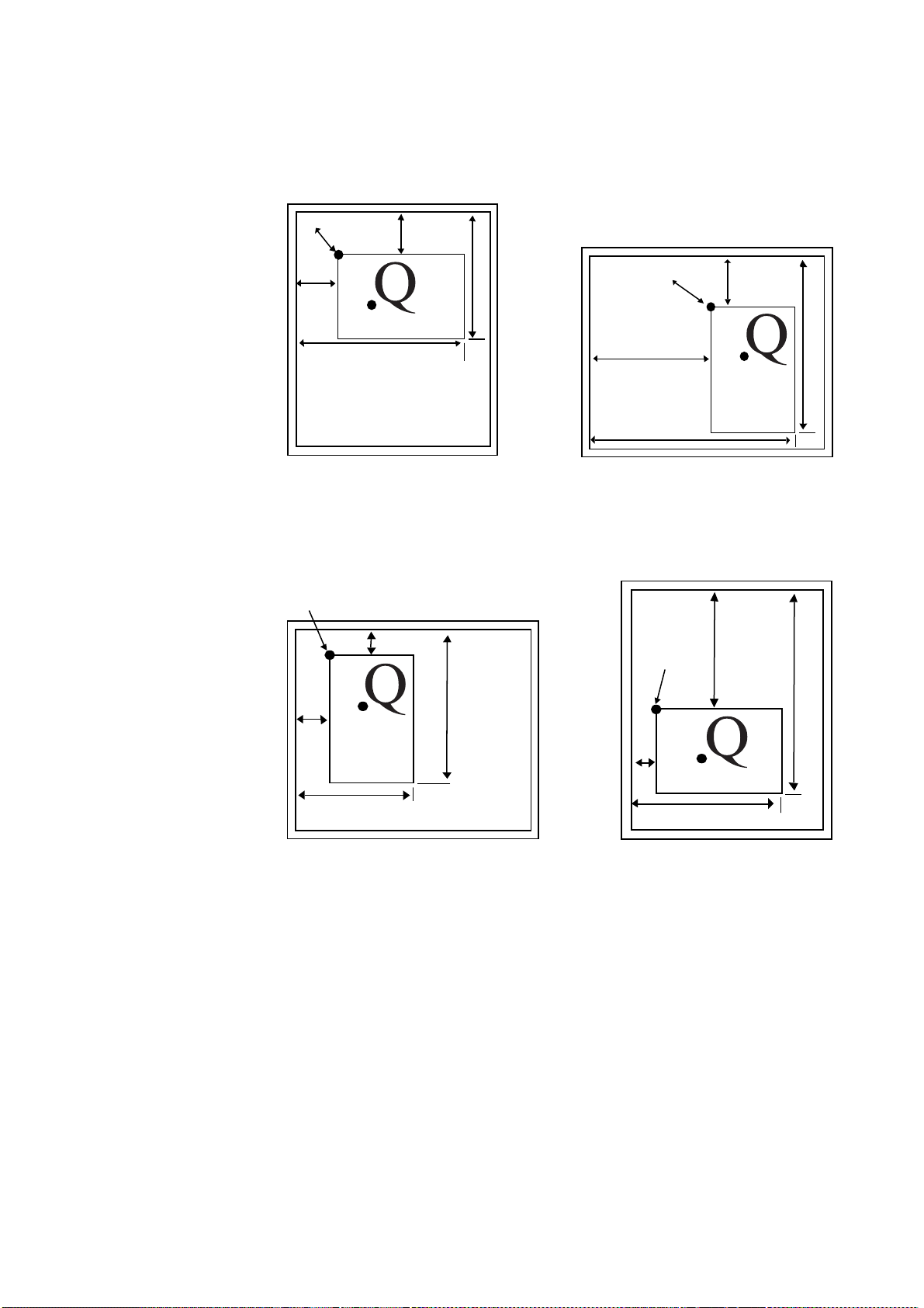
Figure 1. 6. Print Direction
Current Point
Left margin
Right margin
Top
margin
Bottom margin
Current point
Top margin
Right margin
Left
margin
Bottom margin
Right margin
Top margin
Current point
Left margin
Bottom margin
Current Point
Left
margin
Right margin
Top
margin
Bottom margin
Landscape print direction
Portrait print direction
Reverse portrait print direction
Reverse landscape print direction
Basic Concepts
Coordinate Systems
With PRESCRIBE, posit i ons on a page are described in terms of X and Y coordinates.
The origin of the coordinate system (the position at which X and Y both equal 0) is
located at the intersection of the top margin and the left margin. Values of X greater than
0 indicate positions to the right of the origin, and values of Y indicate positions below the
origin. See the figure on page 10. When the top and left margins are changed, the physical position of the origin changes accordingly.
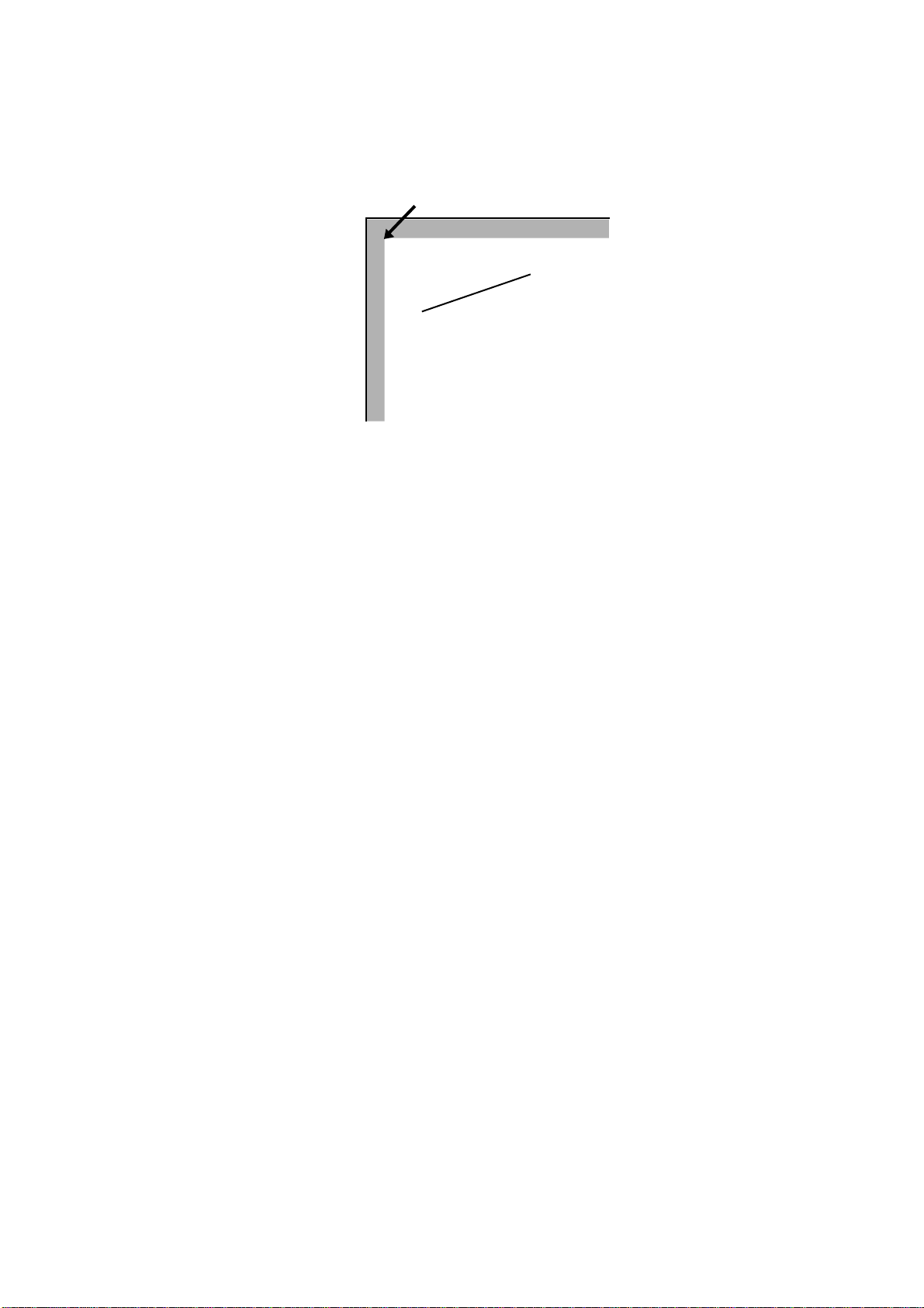
Text Positioning
The printing system always keeps track of its current position on the page. The current
position can be thought of as a cursor that moves as data is printed. At any instant, the
1-7

Chapter 1 Introduction to PRESCRIBE
Carriage Return
Space after EXIT; Cursor ends here
MRP 2, 1;
BOX 1, 1;
cursor indicates where the next character will be printed or the next graphics will be
drawn. (The printing system does not have separate cursors for text and graphics.)
T ex t an d grap hics c an b e po si tio ned at ar bit rary locat io ns on th e page by m ovi ng t he cu rsor with positioning commands (MAP, for example).
Figure 1. 7. Text Positioning
TITLE
!R! BOX 1, 1; MRP 2, 1;
EXIT; LABEL
Landscape Orientation
Character Spacing
Each character is printed within an individual cell as shown below. The character sits on
a line called the baseline. Characters such as y descend below the base line.
In some character fonts, all the character cells are the same size, so the number of character positions per inch is fixed. In other fonts, the size of character cells is proportional to
the size of characters. These proportional fonts produce text that is easier to read. However, in order to align the right margin, you must use software that supports the printing
system’s proportional spacing.
1-8
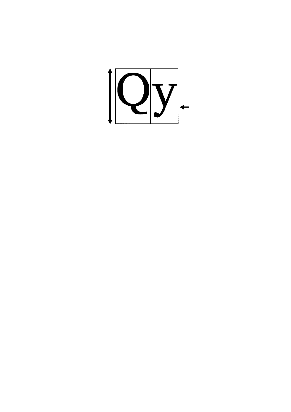
Paths
Font height
Baseline
Basic Concepts
Figure 1. 8. Character Spacing
A path is a set of straight and curved line segments. Paths can be open, as in the case of
lines, or closed, as in the case of rectangles, circles, or any fully enclosed area of any
shape. The segments may be connected with one another, or they may be disconnected.
Further, a path may contain multiple closed subpaths, representing several areas, and
they may intersect themselves in arbitrary ways.
Paths can be used to draw lines and curves or specify boundaries of filled areas, including the outline of a character.
Paths are explained more fully in section Path Mode Graphics on page 16.
Logical Page and Physical Page
The logical page defines the limits of the coordinates within which text and graphics can
be located. There are two types of logical page, as shown in the following figure. The
standard mode logical page imposes limits on specifiable coordinates. The coordinates
have no limitations for the path mode logical page.
1-9

Chapter 1 Introduction to PRESCRIBE
y
x
(0,0)
−x
x
y
−y
Standard Mode
Path Mode
= Logical page
Figure 1. 9. Logical Page and Physical Page
With the standard mode logical page, any position specification that lies outside of the
logical limits is automatically adjusted to bring it within the limits. For example, the
page on the upper left in the preceding figure shows what happens if you attempt to draw
a diagonal line from below the bottom edge limit to a point to the right of the right edge
limit when the standard mode logical page is used. The fine line represents the line as
specified by the user; the thick line shows what is actually drawn by the printing system.
With the path mode logical page, coordinates are not adjusted even if they fall outside of
the edge limits. In this case, as shown in the lower right page in the preceding figure, the
line is defined by the specified starting and ending points, but parts falling outside of the
edge limits are clipped.
Command Parameters
Numeric Parameters
Many of the PRESCRIBE commands use number values to specify parameters. For
example, numbers are used to specify distances in inches, centimeters, points, or dots.
Negative numbers are also allowed.
1-10

Command Parameters
For computer code values beyond four decimal places, the fifth and subsequent decimal
places are ignored.
Examples:
Number output by computer Number used by printing system
1234.1234 1234.1234
-1234.1234 -1234.1234
0.123456 0.1234
Some commands have angle parameters. Angles are specified in degrees. (The printing
system does not recognize radians). The printing system rounds off all angles to the nearest integral degree. Only angles in the range from -360 degrees to 360 degrees are recognized. Angles less than -360 degrees are ignored, and angles greater than 360 degrees are
treated as the remainder of the angle divided by 360.
Examples:
Angle output by computer Angle used by printing system (degrees)
90 90
-90 -90
90.4 90
90.5 91
-400 Ignored
The printing system does not accept the exponential notation used in some computer languages. For example, do not specify 1E-3 instead of 0.001.
Character Strings
PRESCRIBE text-printing commands have parameters that consist of character strings.
A character string is any string of characters enclosed by quotation marks or apostrophes,
such as shown in the example below.
TEXT ’You are about to enter PRESCRIBE.’;
PRESCRIBE allows character strings to be enclosed in either single quotation marks
(apostrophes) or double quotation marks. The following example has exactly the same
meaning as the one above.
TEXT "You are about to enter PRESCRIBE.";
The beginning of a character string is recognized when the first single or double quotation mark appears. If the beginning quotation mark is a single quotation mark, the string
does not end until the next single quotation mark. If the beginning quotation mark is a
double quotation mark, the string does not end until the next double quotation mark.
Whatever comes in the middle of a character string, including commas, semicolons, and
even PRESCRIBE command names, is recognized as part of the character string, and not
as part of the PRESCRIBE command language. For example, the expression EXIT; in
the following string is just text; it does not cause the printing system to exit from the
PRESCRIBE mode.
TEXT ’NO EXIT; NO RETURN.’;
When the string itself contains one type of quotation mark, the quotation mark must be
enclosed in quotes of the other type. Here are two examples:
1-11

Chapter 1 Introduction to PRESCRIBE
TEXT "You’re about to enter PRESCRIBE.";
TEXT ’ " " " ’;
In the first command above, the character string starts with a double quotation mark. The
printing system therefore expects the string to end with a double quotation mark, and
regards the apostrophe in the word You’re as an ordinary character, not as the string terminator.
Similarly, the double quotation marks in the second command above are recognized as
ordinary characters, not as string terminators.
Since an apostrophe or quotation mark can start a character string anywhere in a PRESCRIBE command sequence, it is important not to start character strings unintentionally.
The following examples demonstrate incorrect use of apostrophes and double quotation
marks.
Incorrect:
!R! CMNT Don’t leave stray apostrophes; EXIT;
Incorrect:
!R! CMNT The symbol " means inches; EXIT;
In both of the above cases, the printing system assumes that the expression EXIT; is part
of a character string started by the preceding apostrophe or quotation mark, and fails to
exit the PRESCRIBE mode. The correct way to write these comments is:
Correct:
!R! CMNT "Don’t leave stray apostrophes"; EXIT;
Correct:
!R! CMNT ’The symbol " means inches’; EXIT;
Character strings must not exceed the 255-character limit on total command length. If a
character string exceeds this limit, the printing system terminates it forcibly and begins
looking for the next PRESCRIBE command.
Upper and Lowercase Letters
Regarding upper and lowercase characters, PRESCRIBE follows the same rule as many
computer programming languages: it discriminates case inside character strings and
ignores it elsewhere. You can type command names in upper or lowercase.
Correct:
!R! TEXT ’A’; CIR 1; EXIT;
1-12
Also correct:
!R! text ’A’; cir 1; exit;
Also correct:

Command Parameters
!R! Text ’A’; Cir 1; Exit;
Each of these commands prints the capital letter ‘A’ inside a circle. In the printout shown
above, the unit is centimeters. The reason that the letter ‘A’ is off center in the circle is
that the cursor is not located at the center of the circle, but at left corner of the letter ‘A’.
The command
!R! TEXT ’a’; CIR 1; EXIT;
prints a lowercase a because the letter occurs inside a character string.
The sole exception to upper and lowercase usage in PRESCRIBE commands occurs with
the initializing !R! command. This command must always use an uppercase R. The printing system will not enter the PRESCRIBE mode in response to !r!.
In this manual, PRESCRIBE commands are printed in upper-case for readability.
Outside of PRESCRIBE mode, the printing system always distinguishes between upper-
case and lowercase letters and prints exactly what is sent.
Special Parameters
Some PRESCRIBE commands use unquoted strings of characters as parameters. Examples for these are the FSET (change current font set by characteristic) command and the
CSET (change symbol set by symbol-set ID) command. (See Chapter 4 for a detailed
explanation of how these commands are used to select fonts.)
The FSET and CSET commands use parameters that closely resemble the command
parameters used for font control in Hewlett-Packard’s printer control language. For
example, the PRESCRIBE command
FSET 0p12h12v0s0b6T;
selects the font whose characteristics most closely matches the following font parameters:
• Monospaced font (0p)
• Character spacing of 12 characters/inch (12h)
• Character height of 12 points (12v)
• Upright style (0s)
• Medium weight (0b)
• LetterGothicBM12-Roman typeface (6T)
In Hewlett-Packard’s PCL, the corresponding command would be
ESC(s0p12h12v0s0b6T
1-13

Chapter 1 Introduction to PRESCRIBE
Similarly, the PRESCRIBE command CSET 11U; designates use of the PC-8 Danish/Norwegian symbol set. The corresponding Hewlett-Packard PCL command is
ESC(11U.
1-14

Chapter 2
Graphics Tutorial
PRESCRIBE provides a wide variety of graphics operators, allowing you to easily construct and print almost any imaginable shape or pattern.
This chapter introduces the various graphics concepts of PRESCRIBE, and illustrates
how to use many of its graphic functions. It defines standard graphics mode, path mode
graphics, and raster graphics. It explains how to use predefined fill patterns, how to
define your own fill patterns, and introduces ways in which you can change the print
model, the rules that determine the manner in wh ich patterns and images are rendered on
the paper.

Chapter 2 Graphics Tutorial
Standard Graphics
The standard graphics mode provides a number of operators for constructing a variety of
filled shapes and lines. Using standard mode graphics, you can:
• Draw lines of any desired width
• Draw circles and rectangles
• Draw a variety of filled shapes, including boxes and arcs
• Draw pie charts
This is referred to as the standard graphics mode because it is a standard feature of all
versions of PRESCRIBE.
Drawing Lines
PRESCRIBE provides a number of Draw to commands for drawing lines in both standard and path modes. These include:
DAP (draw to absolute
position)
DZP (draw to zero-relative
position)
DRP (draw to relative position) Draws a line to a position specified as a horizontal and ver-
DRPA (draw to relative
position specified by angle)
Lines to Absolute Position
Begin with a simple task such as drawing a line between two arbitrary points on a page.
Use the MAP and DAP commands to specify positions relative to the top and left margins.
This task has several distinct steps: selecting a line width, determining the starting point
of the line, and determining the end point of the line. The following command sequence
demonstrates this process.
!R! RES;
STM 0.5;
SLM 0.5;
SPD 0.01;
MAP 0.5, 1;
DAP 2, 0.5;
PAGE;
EXIT;
Draws a line to an absolute position in a Cartesian coordinate system whose origin (0,0) is at the intersection of
the left and top margins.
Draws a line to an absolute position in a Cartesian coordinate system whose origin (0,0) is at the intersection of
the left and top edge limits of the paper.
tical displacement from the current cursor position.
Draws a line to a position that is specified as a distance and
angle from the current cursor position. Examples of these
commands are given in the sections that follow.
2-2

Figure 2. 1. Result of Draw Commands: Absolute Lines
Edge limits
Margins
DAP 2, 0.5;
MAP 0.5, 1;
The initial !R! command switches the printing system to the PRESCRIBE mode.
Remember that this command must always precede each sequence of PRESCRIBE commands.
The RES (RESet) clears the current page from printing system memory and re-establishes the printing system’s permanent defaults. Although you would not include this
command in every sequence of PRESCRIBE commands, we include it in this example to
ensure consistent results. As a standard practice, include the RES at the beginning and
end of each job.
The STM and SLM set both the top and left margins to 0.5 inches (1.27 centimeters).
The SPD (Set Pen Diameter) command determines the thickness of lines. In the standard
graphics mode, this setting determines the thickness of all lines drawn after the command
is issued. In this example, the line width is set to 0.01 inches.
The starting point of the line is established with the MAP (Move to Absolute Position)
command. This command moves the cursor to a point that is a specified distance from
the top and left margins. In this example, the point specified is 0.5 inches from the left
margin and 1 inch from the top margin.
If the margins are changed, the position specified by MAP also changes correspondingly .
On the next line of the program, the DAP (Draw to Absolute Position) command draws a
line from the starting position to the point 2 inches from the left margin and 0.5 inches
from the top margin.
Finally, PAGE; prints out the page, allowing us to look at the result of our work.
Zero-relative Lines
The line draw example below uses some new commands to draw another line.
!R! RES;
SPD 0.01;
MZP 0.5, 1;
DZP 2, 0.5;
PAGE;
EXIT;
2-3
Chapter 2 Graphics Tutorial
Edge limits
MZP 0.5, 1;
DZP 2, 0.5;
Figure 2. 2. Result of Draw Commands: Zero-relative Lines
The first two lines switch the printing system to the PRESCRIBE mode, reset printing
system parameters, and set the line width to 0.01 inch. On the third line, the MZP (Move
to Zero-relative Position) differs from the MAP (Move to Absolute Position) command
in one respect: the position specified is in relation to the top and left edge page limits of
the page, rather than in relation to the top and left page margins. MZP moves the cursor
to the point that is 0.5 inches from the left edge limit and 1 inch from the top edge limit.
Similarly, on the next line, DZP (Draw to Zero-relative Position) draws a line from the
starting position to the point 2 inches from the left edge limit and 0.5 inches from the top
edge limit.
Relative Lines
Another way to specify positions is in relation to the current cursor position. The following command sequence provides an example.
!R! RES;
EXIT;
SPD 0.01;
MRP 2, 1;
DRP -1.5, -1;
MRP 2, 1;
DRP -1.5, -1;
MRP 2, 1;
DRP -1.5, -1;
PAGE;
2-4
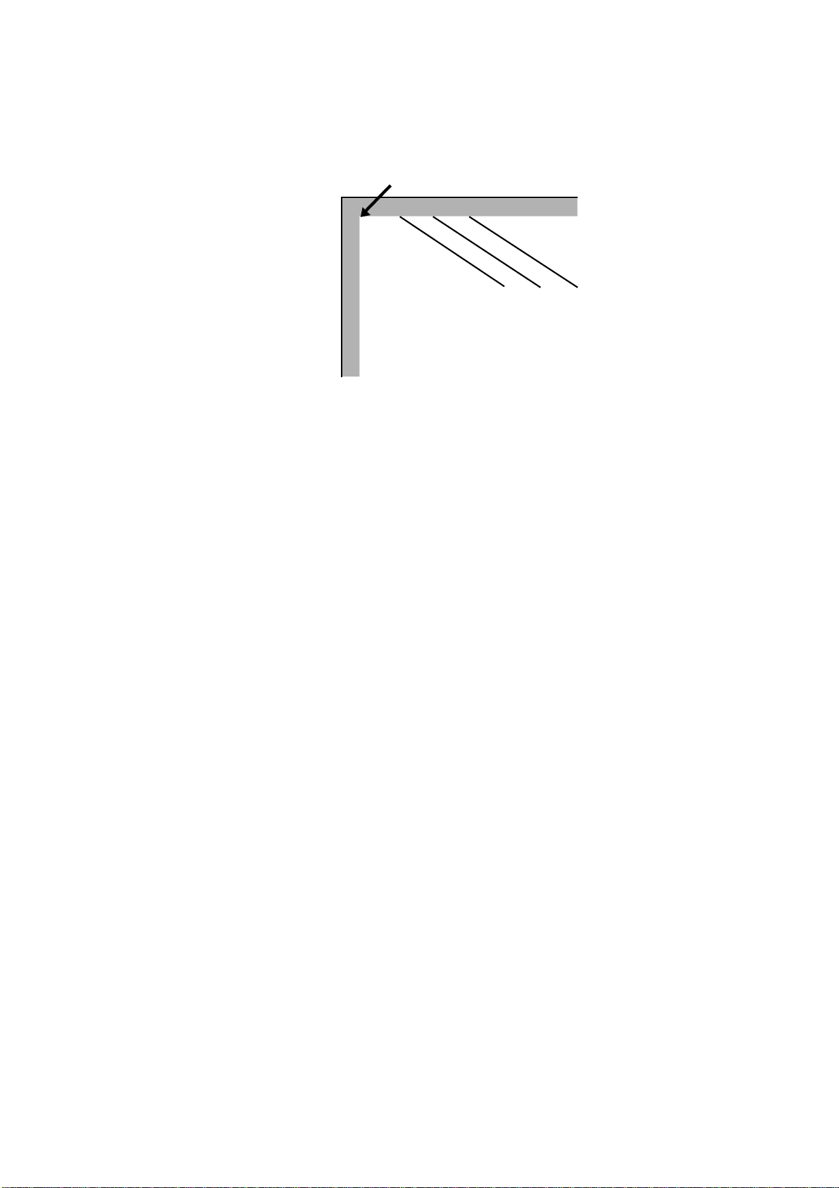
Figure 2. 3. Result of Draw Commands: Relative Lines
Edge limits
In this command sequence, the PRESCRIBE mode begins with the !R!, resets the printing system defaults to permanent settin gs wit h RES;, and es tablis hes a pen width of 0.0 1
inches with the SPD 0.01;.
The MRP (Move to Relative Position) and DRP (Draw to Relative Position) specify
positions in relation to the cursor’s current position.
When the command sequence starts, the cursor is located at the intersection of the left
and top margins. The command MRP 2, 1; on line 3 moves the cursor 2 inches to the
right of its current position, and down 1 inch from its current position. Then the command DRP -1.5, -1; draws a line from that point to a point 1.5 inches to the left of the
cursor position and 1 inch above it. The cursor winds up 0.5 inches to the right of the
point where it started.
Lines 5 to 8 repeat the move-and-draw sequence two more times . Thi s produces three
parallel lines, as shown in the figure on the previous page.
Lines in Terms of Angles
Until now, all of our examples have specified positions in terms of Cartesian (X,Y) coordinates. This example illustrates drawing lines of specified lengths and angles.
!R! RES;
SPD 0.01;
MZP 5, 4;
DRPA 2, 149;
DRPA 2, 221;
DRPA 2, 293;
DRPA 2, 365; CMNT Equivalent to 5 degrees;
DRPA 2, 437; CMNT Equivalent to 77 degrees;
PAGE;
EXIT;
2-5

Chapter 2 Graphics Tutorial
Figure 2. 4. Result of Draw Commands: Lines in Angles
The first two lines of this command sequence initiates the PRESCRIBE mode, resets
printing system defaults to permanent settings, and sets the line width to 0.01 inches.
Then the MZP command on line 3 moves the cursor to a point 5 inches to the right of the
left edge limit and 4 inches below the top edge limit.
Next, DRPA 2, 149; on line 4 draws a line two inches long at an angle of 149 degrees.
The angle is measured clockwise from the vertical axis. The subsequent DRPA commands draw additional 2-inch lines at angles that increase in increments of 72 degrees.
As indicated by the CMNT (CoMmeNT) commands, angles that exceed 360 degrees are
equivalent to the remainder of division of the angle by 360.
Drawing Boxes and Circles
PRESCRIBE provides two commands especially for drawing boxes (BOX command)
and circles (CIR command).
Drawing Boxes
The BOX (draw box) command draws a box of a specified width and height. As with the
line drawing commands, the thickness of the line used to draw the box is determined by
the SPD (set pen diameter) command.
The following command sequence draws a box.
!R! RES;
UNIT C;
SPD 0.1;
MZP 3, 3;
BOX 3, 4;
PAGE;
EXIT;
2-6

Figure 2. 5. An Example of a Box
Line 1 places the printing system in the PRESCRIBE mode and resets printing system
parameters. The UNIT C; command on the second line sets the unit of measurement to
centimeters, and the SPD (Set Pen Diameter) command on line 3 sets the line width to
0.1 centimeters. (If you omit these two commands, the printing system will print using
the default unit, inches; and the default line width, 3dots.)
Next, the MZP command on line four moves the cursor to the point that is 3 centimeters
to the right of the left edge limit and 3 centimeters below the top edge limit. This is the
starting point from which the box is drawn.
On line 5, BOX 3, 4; draws a box with a width of 3 centimeters and a height of 4 centimeters.
The position of the box with respect to the cursor depends on the positive or negative
value specified for width and height. The box is drawn to the right of the cursor if width
is positive, and to the left of the cursor if width is negative. Similarly, the box is drawn
below the cursor if height is positive, and above the cursor if height is negative. This
relation is illustrated in the figure that follows.
By default, the position of the cursor is not affected by this command. However, you can
also specify an option parameter to make the cursor move to an adjacent or diagonally
opposite corner of the box, down by one text line, or to the left margin on the next text
line. The following figure shows some examples.
2-7
Chapter 2 Graphics Tutorial
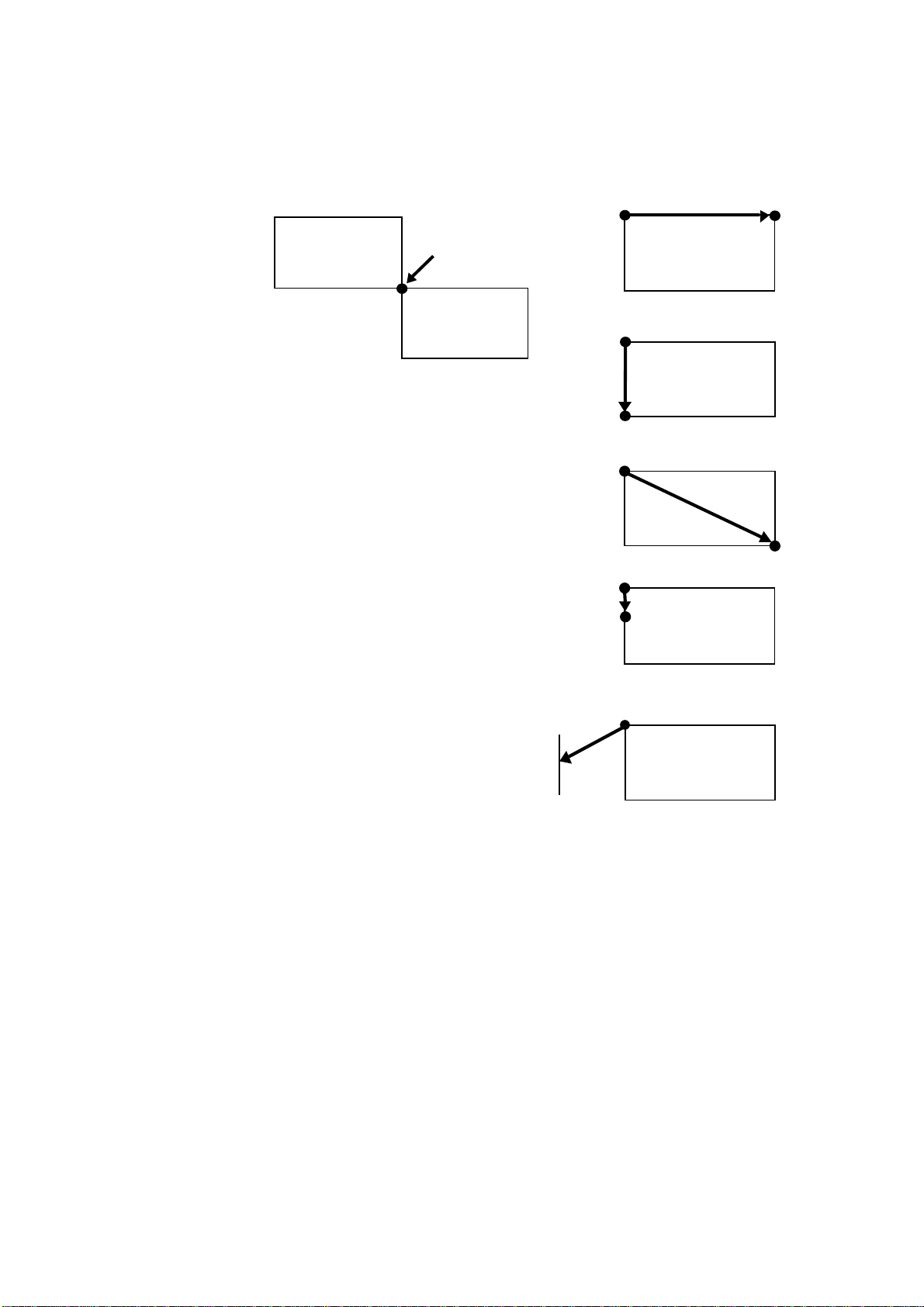
X
BOX 4, 2, H; Moves the cursor to
the horizontally adjacent corner
BOX 4, 2, V; Moves the cursor to
the vertically adjacent corner
BOX 4, 2, E; Moves the cursor to
the diagonally opposite corner
BOX 4, 2, L; Moves the cursor
down one line
BOX 4, 2, N; Moves the cursor to
the beginning of the next line (to
the left margin)
Left margin
Cursor position
-X
-Y
Y
Figure 2. 6. Cursor Positioning Options
2-8
Loading...